EP4456302A1 - Battery module - Google Patents
Battery module Download PDFInfo
- Publication number
- EP4456302A1 EP4456302A1 EP23211114.6A EP23211114A EP4456302A1 EP 4456302 A1 EP4456302 A1 EP 4456302A1 EP 23211114 A EP23211114 A EP 23211114A EP 4456302 A1 EP4456302 A1 EP 4456302A1
- Authority
- EP
- European Patent Office
- Prior art keywords
- battery
- guiding
- mounting
- supporting frame
- battery module
- Prior art date
- Legal status (The legal status is an assumption and is not a legal conclusion. Google has not performed a legal analysis and makes no representation as to the accuracy of the status listed.)
- Granted
Links
Images



Classifications
-
- H—ELECTRICITY
- H01—ELECTRIC ELEMENTS
- H01M—PROCESSES OR MEANS, e.g. BATTERIES, FOR THE DIRECT CONVERSION OF CHEMICAL ENERGY INTO ELECTRICAL ENERGY
- H01M50/00—Constructional details or processes of manufacture of the non-active parts of electrochemical cells other than fuel cells, e.g. hybrid cells
- H01M50/20—Mountings; Secondary casings or frames; Racks, modules or packs; Suspension devices; Shock absorbers; Transport or carrying devices; Holders
- H01M50/204—Racks, modules or packs for multiple batteries or multiple cells
- H01M50/207—Racks, modules or packs for multiple batteries or multiple cells characterised by their shape
- H01M50/211—Racks, modules or packs for multiple batteries or multiple cells characterised by their shape adapted for pouch cells
-
- H—ELECTRICITY
- H01—ELECTRIC ELEMENTS
- H01M—PROCESSES OR MEANS, e.g. BATTERIES, FOR THE DIRECT CONVERSION OF CHEMICAL ENERGY INTO ELECTRICAL ENERGY
- H01M10/00—Secondary cells; Manufacture thereof
- H01M10/42—Methods or arrangements for servicing or maintenance of secondary cells or secondary half-cells
- H01M10/48—Accumulators combined with arrangements for measuring, testing or indicating the condition of cells, e.g. the level or density of the electrolyte
- H01M10/482—Accumulators combined with arrangements for measuring, testing or indicating the condition of cells, e.g. the level or density of the electrolyte for several batteries or cells simultaneously or sequentially
-
- H—ELECTRICITY
- H01—ELECTRIC ELEMENTS
- H01M—PROCESSES OR MEANS, e.g. BATTERIES, FOR THE DIRECT CONVERSION OF CHEMICAL ENERGY INTO ELECTRICAL ENERGY
- H01M10/00—Secondary cells; Manufacture thereof
- H01M10/42—Methods or arrangements for servicing or maintenance of secondary cells or secondary half-cells
- H01M10/48—Accumulators combined with arrangements for measuring, testing or indicating the condition of cells, e.g. the level or density of the electrolyte
- H01M10/486—Accumulators combined with arrangements for measuring, testing or indicating the condition of cells, e.g. the level or density of the electrolyte for measuring temperature
-
- H—ELECTRICITY
- H01—ELECTRIC ELEMENTS
- H01M—PROCESSES OR MEANS, e.g. BATTERIES, FOR THE DIRECT CONVERSION OF CHEMICAL ENERGY INTO ELECTRICAL ENERGY
- H01M50/00—Constructional details or processes of manufacture of the non-active parts of electrochemical cells other than fuel cells, e.g. hybrid cells
- H01M50/20—Mountings; Secondary casings or frames; Racks, modules or packs; Suspension devices; Shock absorbers; Transport or carrying devices; Holders
- H01M50/284—Mountings; Secondary casings or frames; Racks, modules or packs; Suspension devices; Shock absorbers; Transport or carrying devices; Holders with incorporated circuit boards, e.g. printed circuit boards [PCB]
-
- H—ELECTRICITY
- H01—ELECTRIC ELEMENTS
- H01M—PROCESSES OR MEANS, e.g. BATTERIES, FOR THE DIRECT CONVERSION OF CHEMICAL ENERGY INTO ELECTRICAL ENERGY
- H01M50/00—Constructional details or processes of manufacture of the non-active parts of electrochemical cells other than fuel cells, e.g. hybrid cells
- H01M50/30—Arrangements for facilitating escape of gases
- H01M50/35—Gas exhaust passages comprising elongated, tortuous or labyrinth-shaped exhaust passages
- H01M50/358—External gas exhaust passages located on the battery cover or case
-
- H—ELECTRICITY
- H01—ELECTRIC ELEMENTS
- H01M—PROCESSES OR MEANS, e.g. BATTERIES, FOR THE DIRECT CONVERSION OF CHEMICAL ENERGY INTO ELECTRICAL ENERGY
- H01M50/00—Constructional details or processes of manufacture of the non-active parts of electrochemical cells other than fuel cells, e.g. hybrid cells
- H01M50/30—Arrangements for facilitating escape of gases
- H01M50/383—Flame arresting or ignition-preventing means
-
- H—ELECTRICITY
- H01—ELECTRIC ELEMENTS
- H01M—PROCESSES OR MEANS, e.g. BATTERIES, FOR THE DIRECT CONVERSION OF CHEMICAL ENERGY INTO ELECTRICAL ENERGY
- H01M50/00—Constructional details or processes of manufacture of the non-active parts of electrochemical cells other than fuel cells, e.g. hybrid cells
- H01M50/50—Current conducting connections for cells or batteries
- H01M50/543—Terminals
- H01M50/547—Terminals characterised by the disposition of the terminals on the cells
- H01M50/548—Terminals characterised by the disposition of the terminals on the cells on opposite sides of the cell
-
- H—ELECTRICITY
- H01—ELECTRIC ELEMENTS
- H01M—PROCESSES OR MEANS, e.g. BATTERIES, FOR THE DIRECT CONVERSION OF CHEMICAL ENERGY INTO ELECTRICAL ENERGY
- H01M2200/00—Safety devices for primary or secondary batteries
- H01M2200/10—Temperature sensitive devices
- H01M2200/103—Fuse
-
- Y—GENERAL TAGGING OF NEW TECHNOLOGICAL DEVELOPMENTS; GENERAL TAGGING OF CROSS-SECTIONAL TECHNOLOGIES SPANNING OVER SEVERAL SECTIONS OF THE IPC; TECHNICAL SUBJECTS COVERED BY FORMER USPC CROSS-REFERENCE ART COLLECTIONS [XRACs] AND DIGESTS
- Y02—TECHNOLOGIES OR APPLICATIONS FOR MITIGATION OR ADAPTATION AGAINST CLIMATE CHANGE
- Y02E—REDUCTION OF GREENHOUSE GAS [GHG] EMISSIONS, RELATED TO ENERGY GENERATION, TRANSMISSION OR DISTRIBUTION
- Y02E60/00—Enabling technologies; Technologies with a potential or indirect contribution to GHG emissions mitigation
- Y02E60/10—Energy storage using batteries
Definitions
- the present application relates to the technical field of batteries, in particular to a battery module.
- Lithium batteries applied to new energy vehicles include prismatic batteries and cylinder batteries, of which prismatic batteries include pouch batteries and hard-pack batteries, of which hard-pack batteries include blade batteries, and blade batteries are significantly guiding the market with their ultra-high energy density.
- prismatic batteries include pouch batteries and hard-pack batteries
- hard-pack batteries include blade batteries
- blade batteries are significantly guiding the market with their ultra-high energy density.
- two electrode columns of a blade battery are provided oppositely in a length direction of the battery.
- a battery module including: a battery group, the battery group including a plurality of batteries, the battery including a positive electrode column and a negative electrode column, the positive electrode column and the negative electrode column being provided oppositely in a length direction of the battery; a cells contact system (hereinafter referred as CCS) assembly, provided on a side of the battery group, electrically connected to the battery group, used for collecting and transferring an electrical signal of the battery group; a beam, provided opposite the CCS assembly, a pressure relief channel being provided within the beam; and a guiding structure, connected between the battery group and the beam, the guiding structure being provided with a plurality of guiding channels, each guiding channel being in communication with the pressure relief channel, each guiding channel being provided corresponding to an explosion-proof valve of the battery, wherein the guiding channel is used for guiding high-temperature gas and/or high-temperature fluid ejected from the explosion-
- CCS cells contact system
- the guiding structure is provided with a plurality of guiding channels, each guiding channel being provided corresponding to an explosion-proof valve of the battery.
- the high-temperature gas or fluid ejected from the explosion-proof valve may flow to the pressure relief channel through the guiding structure and be dispersed through the beam, avoiding splashing to the surrounding batteries and affecting the operating safety of the entire battery module. Therefore, the safety of the entire battery module is improved by providing a guiding structure.
- the CCS assembly includes: a supporting frame, provided in a height direction of the battery, supported on a lateral side of the battery group; a connection plate, mounted on the supporting frame, electrically connected to the positive electrode column and the negative electrode column respectively; and a collecting structure, mounted on the supporting frame, electrically connected to the connection plate and the battery group respectively, the collecting structure being used for transferring the electrical signal of the battery group.
- the supporting frame may provide support in a height direction of the battery group, and the supporting frame is a structure with a certain degree of hardness, which may facilitate support and installation between the connection plate and the collecting structure.
- the entire CCS assembly may be clamped by mechanization, which achieves the mechanized installation between the CCS assembly and the battery group, thereby improving the assembling efficiency of the entire battery module.
- connection plate includes a plurality of sub-plates, the supporting frame being provided with a plurality of mounting holes, each sub-plate being mounted into each mounting hole.
- a reserved gap is provided between the sub-plate and an interior wall of the mounting hole.
- connection plate is detachably connected to the supporting frame.
- connection plate is snap-fitted to the supporting frame.
- the collecting structure includes a flexible printed circuit (FPC), a connector electrically connected to the FPC, a plurality of electrical signal collecting members and a plurality of temperature collecting members, the electrical signal collecting member being electrically connected to the connection plate, the temperature collecting member being electrically connected to the battery;
- the FPC is connected to the supporting frame, including a first segment and a second segment connected with each other, the first segment extending in an alignment direction of each battery, the second segment being provided on a side of the battery in a thickness direction, wherein the first segment is used for mounting the electrical signal collecting member and the temperature collecting member, and the second segment is used for mounting the connector.
- FPC flexible printed circuit
- the collecting structure also includes a fuse protection structure, and the fuse protection structure is provided on the second segment.
- the fuse protection structure is a patch fuse, and the patch fuse is welded to the second segment.
- the FPC is connected to the supporting frame by hot riveting.
- a mounting structure is provided on the supporting frame, and the mounting structure is used for mounting a lateral cap.
- the mounting structure is detachably connected to the lateral cap.
- the supporting frame is a composite supporting frame made of polycarbonate (PC) and acrylonitrile butadiene styrene (ABS).
- PC polycarbonate
- ABS acrylonitrile butadiene styrene
- a weight-loss hole and an escaping hole corresponding to the explosion-proof valve of the battery are provided on the supporting frame.
- an end of the guiding structure is fixedly connected to the battery group, and an opposite end of the guiding structure is detachably connected to a beam.
- the guiding structure includes a plurality of independent guiding member, each guiding member being formed each guiding channel, each guiding member being provided corresponding to each explosion-proof valve.
- the guiding member includes a tube body, a first sealing ring and a second sealing ring provided at opposite ends of the tube body, the first sealing ring being bonded to the battery, the second sealing ring being snap-fitted to the beam.
- the tube body is a metal tube.
- a shape of the tube body is adapted to a shape of the explosion-proof valve.
- a length range of the tube body in a length direction of the battery is 2-5cm.
- the tube body includes a main body, a first mounting platform and a second mounting platform that are provided at opposite ends of the main body; the first mounting platform protrudes from the main body along a perimeter of the main body, the first mounting platform being used for mounting the first sealing ring; and the second mounting platform protrudes from the main body along a perimeter of the main body, the second mounting platform being used for mounting the second sealing ring.
- a first groove is provided on the first mounting platform in a side towards the battery, and the first sealing ring is provided in the first groove.
- a snap-fit groove is provided on a side wall of the first mounting platform, and the supporting frame is snap-fitted in the snap-fit groove.
- a pressure relief channel extends in an alignment direction of the battery and penetrates the beam.
- the beam is provided with at least one reinforcing ribs in the pressure relief channel, and the reinforcing rib is extended in a horizontal direction.
- the meanings of the attached markings are as follows: 100 battery module; 10 battery group; 11 battery; 111 positive electrode column; 112 negative electrode column; 113 explosion-proof valve; 20 CCS assembly; 21 supporting frame; 211 mounting hole; 212 buckle; 213 hot riveting post; 214 gap; 215 mounting structure; 2151 connection piece; 2152 snap-fit protrusion; 216 weight-loss hole; 217 escaping hole; 22 connection plate; 221 sub-plate; 23 collecting structure; 231 flexible printed circuit (FPC); 2311 first segment; 2312 second segment; 232 temperature collecting member; 233 electrical signal collecting member; 234 connector; 235 fuse protection structure; 30 beam; 31 pressure relief channel; 32 first stepped snap-fit position; 33 second stepped snap-fit position; 34 through-hole; 35 reinforcing rib; 40 guiding structure; 41 guiding channel; 42 guiding member; 421 tube body; 4211 first mounting platform; 4212 first groove; 4213 second mounting platform; 4214 snap-fit groove; 4215 main body; 422 first sealing ring
- a battery module 100 including a battery group 10, a CCS assembly 20, a beam 30 and a guiding structure 40.
- the battery group 10 includes a plurality of batteries 11, the battery 11 including a positive electrode column 111 and a negative electrode column 112, the positive electrode column 111 and the negative electrode column 112 being provided oppositely in a length direction X of the battery 11; a CCS assembly 20, provided on a side of the battery group 10, electrically connected to the battery group 10, used for collecting and transferring an electrical signal of the battery group 10; a beam 30, provided opposite the CCS assembly 20, a pressure relief channel 31 being provided within the beam 30; and a guiding structure 40, connected between the battery group 10 and the beam 30, the guiding structure 40 being provided with a plurality of guiding channels 41, each guiding channel 41 being in communication with the pressure relief channel 31, each guiding channel 41 being provided corresponding to an explosion-proof valve 113 of the battery 11, wherein the guiding channel 41 is used for guiding high-temperature gas and/or high-temperature fluid ejected from the explosion-proof valve 113 into the pressure relief channel 31 when thermal runaway
- the guiding structure 40 is provided with a plurality of guiding channels 41, each guiding channel 41 being provided corresponding to an explosion-proof valve 113 of the battery 11.
- the high-temperature gas or fluid ejected from the explosion-proof valve 113 may flow to the pressure relief channel 31 through the guiding structure 40 and be dispersed through the beam 30, avoiding splashing to the surrounding batteries 11 and affecting the operating safety of the entire battery module 100. Therefore, the safety of the entire battery module 100 is improved by providing a guiding structure 40.
- the battery 11 of the present embodiment is a blade battery, a positive electrode column 111 and a negative electrode column 112 of the blade battery being provided at opposite ends of the battery 11 in a length direction X, the explosion-proof valve 113 and the positive electrode column 111 are provided at the same end of the battery 11.
- the length direction X of the battery 11 is a width direction of the battery module 100; the width direction Y of the battery 11 is an alignment direction of the battery 11; and the height direction Z of the battery 11 is a height direction Z of the battery module 100.
- the guiding structure 40 of the present embodiment penetrates the CCS assembly 20 when assembling. That is, the CCS assembly 20 is provided on a side of the battery group 10 in the X direction when assembling.
- the CCS assembly 20 in order to facilitate the installation of the entire CCS assembly 20, and improve the mounting efficiency of the entire CCS assembly 20, the CCS assembly 20 includes a supporting frame 21, a connection plate 22 and a collecting structure 23, wherein the supporting frame 21 is provided on the battery 11 in the height direction Z and supports a lateral side of the battery group 10; the connection plate 22 is mounted on the supporting frame 21 and electrically connected to the positive electrode column 111 and the negative electrode column 112 respectively; and the collecting structure 23 is mounted on the supporting frame 21 and electrically connected to the connection plate 22 and the battery group 10 respectively, used for transferring the signal of the battery group 10.
- the supporting frame 21 may provide support in a height direction Z of the battery group 10, and the supporting frame 21 is a structure with a certain degree of hardness, which may facilitate support and installation between the connection plate 22 and the collecting structure 23.
- the entire CCS assembly 20 may be clamped by mechanization, which achieves the mechanized installation between the CCS assembly 20 and the battery group 10, thereby improving the assembling efficiency of the entire battery module 100.
- the collecting structure 23 includes an FPC 231, a plurality of temperature collecting members 232 electrically connected to the FPC 231, a plurality of electrical signal collecting members 233 and a connector 234.
- the connection plate 22 and the FPC 231 are provided sequentially from top to bottom in the height direction Z of the battery 11.
- the connection plate 22 is used for achieving the electrical connection of the battery group 10, specifically, electrically connected to the positive electrode column 111 and the negative electrode column 112 respectively, so as to achieve the series connection within the battery group 10.
- the electrical signal collecting member 233 is used for collecting the voltage signal of the battery group 10, specifically, electrically connected between the connection plate 22 and the FPC 231, so as to transfer the electrical signal to the FPC 231.
- the temperature collecting member 232 is used for collecting the temperature signal of the battery group 10, specifically, electrically connected between the battery 11 and the FPC 231, so as to transfer the temperature signal of the battery group 10 to the FPC 231.
- the electrical connection with the battery group 10 is achieved by the connection plate 22; the voltage signal of the battery group 10 transferred to the FPC 231 is achieved by the electrical signal collecting member 233; the temperature signal of the battery group 10 transferred to the FPC 231 is achieved by the temperature collecting member 232; and finally the signal transferring with external structures is achieved by the connector 234, for example, the signal transferring with the battery management system (BMS).
- BMS battery management system
- the connection plate 22 when electrically connecting the connection plate 22 to the battery group 10, the connection plate 22 includes a plurality of sub-plates 221, the supporting frame 21 being provided with a plurality of mounting holes 211, wherein each sub-plate 221 is mounted into each mounting hole 211, and each sub-plate 221 is connected to the positive electrode column 111 and the negative electrode column 112 of each two adjacent batteries 11, so as to achieve the series connection of the battery group 10 by the connection plate 22 when mounting the CCS assembly 20 to the battery group 10. That is, current flows from a positive electrode column 111 of a battery 11 to a negative electrode column 112, and flows from the negative electrode column 112 to a positive electrode column 111 of an adjacent battery 11, so that a series connection within the battery group 10 is achieved.
- each sub-plate 221 in the present embodiment is welded between a positive electrode column 111 and a negative electrode column 112 of each two adjacent batteries 11, which achieves electrical connection and also the conductivity of current.
- connection plate 22 in the present embodiment is an aluminum plate, which may be a copper plate in the other embodiments, which is not limited hereby.
- the supporting frame 21 when mounting each sub-plate 221 to the supporting frame 21, the supporting frame 21 includes a plurality of mounting holes 211, and each sub-plate 221 is mounted into each mounting hole 211.
- the supporting frame 21 By providing mounting holes 211 on the supporting frame 21, not only is the positioning of the sub-plate 211 is achieved, but also the installation of the sub-plate 211 is achieved.
- a shape of the mounting hole 211 is adapted to a shape of the sub-plate 211.
- the sub-plate 221 is pentagon in shape
- the mounting hole 211 is also pentagon in shape, so that the sub-plate 221 is just correspondingly mounted into the mounting hole 211.
- connection plate 22 when mounting the sub-plate 221 into the mounting hole 211 and before welding the connection plate 22 to electrode columns, the connection plate 22 is detachably mounted into the mounting hole 211. That is, each sub-plate 211 is correspondingly detachably mounted into each mounting hole 211, so that each position of the sub-plate 221 corresponding to the battery 11 is adjusted into the position of the mounting hole 211.
- the supporting frame 21 is provided with a buckle 212, and the buckle 212 is used for setting the sub-plate 221 into the mounting hole 211. That is, the sub-plate 221 is detachably mounted into the mounting hole 211 by snap-fitting.
- the supporting frame 21 Before welding each sub-plate 221 to electrode columns, in order to ensure the mounting stability of the sub-plate 221 mounted into the mounting hole 211, the supporting frame 21 is provided with a plurality of buckles 212 corresponding to each position of the mounting hole 211, and a plurality of buckles 212 are separately provided on a plurality of side walls of the mounting holes 211, so as to fix the sub-plate 221 from multiple directions, thereby ensuring the stability of the sub-plate 221 mounted into the mounting hole 211.
- a reserved gap 214 is provided between the connection plate 22 and an internal wall of the mounting hole 211, so that the position of the sub-plate 221 may be adjusted to align each adjacent two electrode columns when mounting the CCS assembly 20 and the battery group 10, and the sub-plate 221 is welded to two electrode columns respectively.
- a reserved gap 214 is provided between the connection plate 22 and an internal wall of the mounting hole 211, errors may be adjusted, which facilitates the welding of corresponding region between the sub-plate 221 and electrode columns.
- the FPC 231 in order to accommodate the temperature collecting member 232, the electrical signal collecting member 233 and the connector 234 to be mounted on the FPC 231 respectively, the FPC 231 includes a first segment 2311 and a second segment 2312 connected with each other, the first segment 2311 extending in an alignment direction of each battery 11, the second segment 2312 being provided on a side of the battery 11 in a thickness direction, wherein the first segment 2311 is used for mounting the electrical signal collecting member 233 and the temperature collecting member 232, and the second segment 2312 is used for mounting the connector 234.
- the FPC 231 is provided by being divided into two segments, which achieves the electrical signal collecting of the battery group 10 and achieves the signal transferring with external structures by the connector 234, for example, the signal transferring with the battery management system (BMS). Also, since the FPC 231 is provided with certain flexibility, which may be bent and mounted on different sides of the battery group 10, thereby facilitating the installation of each component within the battery module 100.
- BMS battery management system
- the first segment 2311 is provided on an end of a length direction X of the battery 11, that is, extends in an alignment direction of the battery group 10; the second segment 2312 is provided in a thickness direction Y of the battery 11, that is, provided on a large-surface direction of the battery 11, so that the connector 234 mounted on the second segment 2312 may correspond the installation of the BMS.
- the FPC 231 when mounting the FPC 231 to the supporting frame 21, the FPC 231 is connected to the supporting frame 21 by hot riveting, that is, the supporting frame 21 is provided with a hot riveting post 213, and the FPC 231 is mounted to the supporting frame 21 by the hot riveting post 213.
- the mounting stability of the FPC 231 and the supporting frame 21 is ensured.
- the temperature collecting member 232 in the present embodiment is a nickel sheet.
- an amount of the nickel sheets corresponds to an amount of the sub-plates 221; each nickel sheet is connected to each sub-plate 221 correspondingly, so as to achieve the collecting of the voltage information of the battery 11 by the nickel sheet.
- the supporting frame 21 is provided with a gap 214, the gap 214 being in communication with the mounting hole 211, so as to connect the nickel sheet between the connection plate 22 and the FPC 231.
- the temperature collecting member 232 in the present embodiment is a temperature collecting chip.
- an amount of the temperature collecting members 232 provided therein may less than the amount of the sub-plates 221.
- the opposite ends and the middle of the first segment 2311 of the FPC 231 are provided with a temperature collecting member 232 respectively.
- One temperature collecting member 232 achieves the temperature collecting of one region, so as to achieve the monitoring of the battery operating condition by BMS.
- the collecting structure 23 also includes a fuse protection structure 235, and the fuse protection structure 235 is connected to the FPC 231, specifically, connected to the second segment 2312 of the FPC 231. That is, the fuse protection structure 235 and the connector 234 are collectively provided on the second segment 2312.
- the CCS assembly 20 may fuse when the current in the CCS assembly 20 is too high, so as to protect the battery group 10.
- the fuse protection structure 235 in the present embodiment is a patch fuse, and the patch fuse is welded to the second segment 2312.
- the fuse protection structure 235 in the present embodiment may be replaced after being damaged, so that the entire FPC 231 may be utilized once again, which provides with an advantage of reducing cost.
- the guiding structure 40 When mounting the guiding structure 40 of the present embodiment, since the FPC 231 is provided below the connection plate 22, the guiding structure 40 penetrates the supporting frame 21 and the FPC 231, so as to achieve the connection between the guiding structure 40 and the position of the battery group 10 where the explosion-proof valve 113 is located, which achieves not only the connection between the guiding structure 40 and the battery group 10 but also the installation between the guiding structure 40 and the CCS assembly 20.
- the supporting frame 21 of the present embodiment is provided with a mounting structure 215, and the mounting structure 215 is used for mounting a lateral cap.
- the mounting structure 215 is integrally formed from the supporting frame 21, which facilitate the installation of the lateral cap of the battery module 100, thereby improving the mounting efficiency of the battery module 100.
- the mounting structure 215 is provided for detachably connecting the lateral cap, which facilitates the installation of the lateral cap by a detachable connection, and also facilitates the maintenance of the battery group 10 after subsequent dismounting of the lateral cap.
- the mounting structure 215 in the present embodiment includes a connection piece 2151 and a snap-fit protrusion 2152 provided on the connection piece 2151, the connection piece 2151 extending to a top direction of the battery group 10, the snap-fit protrusion 2152 being used for being snap-fitted to the lateral cap.
- the supporting frame 21 may be provided with a plurality of mounting structures 215 in the alignment direction of the battery group 10. In such a setup, the mounting stability of the lateral cap is ensured.
- the supporting frame 21 in the present embodiment is a polymer composite supporting frame 21 made of polycarbonate (PC) and acrylonitrile butadiene styrene (ABS).
- the polymer composite support frame 21 made of ABS and PC provides the advantages of high anti-impact strength, good texture, durability and particularly high resistance to thermal deformation, so as to provide a certain level of supporting strength for mounting and fixing the collecting structure 23 and the connection plate 22.
- the supporting frame 21 prepared from the polymer composite supporting frame 21 made of PC and ABS in the present embodiment may be formed quickly, which further improves the mounting efficiency of the entire CCS assembly 20.
- escaping holes 217 are provided on the positions of the supporting frame 21 corresponding to each explosion-proof valve 113 of the batteries.
- the supporting frame 21 in the present embodiment is provided with a weight-loss hole 216, and the weight-loss hole 216 is provided for reducing weight of the supporting frame 21.
- a weight-loss hole 216 and an escaping hole 217 are alternately provided so as to fully utilize the area of each two adjacent escaping holes 217 to provide weight-loss holes 216 to achieve weight reduction.
- an end of the guiding structure 40 when mounting the guiding structure 40, an end of the guiding structure 40 is fixedly connected to the battery group 10, and an opposite end of the guiding structure 40 is detachably connected to a beam 30, so as to ensure the connection sealing between the guiding structure 40 and the battery group 10.
- an opposite end of the guiding structure 40 By detachably connecting the opposite end of the guiding structure 40 to the beam 30, after assembling the guiding structure 40 and the battery group 10, it is convenient to connect the beam 30 to the guiding structure 40.
- the guiding structure 40 when mounting the guiding structure 40 to the battery group 10 and the beam 30, an end of the guiding structure 40 is bonded to the battery group 10, and an opposite end of the guiding structure 40 is snap-fitted to the beam 30. After mounting the guiding structure 40 to the battery group 10, the beam 30 is tightly snap-fitted to the guiding structure 40, so as to achieve the installation of the entire battery module 100.
- the guiding structure 40 is provided with a plurality of guiding channels 41, each guiding channel 41 being in communication with the pressure relief channel 31, each guiding channel 41 is provided corresponding to each explosion-proof valve 113 of a battery 11.
- the guiding channel 41 may be provided for including two sections. One section includes a plurality of sub-channels, and the sub-channel is provided corresponding to each explosion-proof valve 113 of a battery 11. Another section may aggregate the high-temperature and high-pressure gas and fluid flowing from the sub-channels and then forward them to the beam 30, so that conductivity of high-temperature and high-pressure gas and fluid may also be achieved.
- each guiding channel 41 is provided corresponding to each explosion-proof valve 113 of a battery 11, referring to Fig. 5 , Fig. 6 , Fig. 16 and Fig. 17 , the guiding structure 40 includes a plurality of independent guiding member 42, each guiding member 42 being formed each guiding channel 41, each guiding member 42 being provided corresponding to each explosion-proof valve 113 of a battery 11.
- each guiding member 42 is formed individually.
- one guiding member 42 When connecting the guiding member 42 to the battery group 10, one guiding member 42 is required to be aligned with one explosion-proof valve 113 of the battery 11, so as to easily and accurately install each guiding member 42 individually at the explosion-proof valve 113, which improves the mounting accuracy of the guiding member 42.
- the guiding structure 40 may be provided for including a plurality of guiding members 42 and connecting ribs connected between a plurality of guiding members 42.
- the guiding members 42 are connected to be formed as a whole by connecting ribs.
- the entire guiding structure 40 may be an integrally provided structure, so as to improve the production efficiency of the entire guiding structure 40.
- connecting ribs and guiding members 42 are structures formed individually, and then the guiding members 42 are mounted on the connecting ribs, so that the connecting ribs and the guiding members 42 are formed as one mounting unit.
- the guiding structure 40 when mounting the entire guiding structure 40, the guiding structure 40 may be mounted on the entire battery group 10 all at once, which improves the mounting efficiency.
- the guiding structure 40 when the guiding structure 40 is provided as an integral structure, a plurality of guiding channels 41 may be provided on an integral guiding structure 40, and an amount of the guiding channels 41 is identical to an amount of the explosion-proof valves 113, which may achieve that each explosion-proof valve 113 may relief pressure correspondingly.
- a shape of the guiding member 42 of the present embodiment is provided to be adapted to a shape of the explosion-proof valve 113, which may fully achieve the guiding of the electrolyte flowed from the explosion-proof valve 113.
- the guiding member 42 is provided in an oval shape; when the explosion-proof valve 113 is circular, the guiding member 42 is circular.
- the guiding member 42 may be provided to enclose precisely around the explosion-proof valve 113 to allow the electrolyte to flow out, avoiding the electrolyte from flowing onto the cover of the battery 11 when the cross-sectional area of the guiding member 42 is greater than that of the explosion-proof valve 113; or it avoids the electrolyte from leaking and flowing onto an adj acent battery 11 when the cross-sectional area of the guide member 42 is less than that of the explosion-proof valve 113.
- the guiding member 42 when providing the guiding member 42 in the present embodiment, in order to ensure the connecting sealing between the guiding member 42, the battery 11 and the beam 30, the guiding member 42 includes a tube body 421, a first sealing ring 422 and a second sealing ring 423 provided at opposite ends of the tube body 421, the first sealing ring 422 being bonded to the battery 11, the second sealing ring 423 being snap-fitted to the beam 30.
- the connecting sealing of the tube body 421 at opposite ends with the battery 11 and the beam 30 is ensured respectively, which avoids high-temperature gas or fluid leaking out from the connection of the tube body 421.
- the end of the tube body 421 connected to the battery 11 and the first sealing ring 422 are collectively bonded to the battery 11; when mounting the second sealing ring 423 on the beam 30, an interference fit may be adopted to tightly snap-fit the opposite end of the tube body 421 to the beam 30.
- the tube body 421 in the present embodiment is a metal tube.
- Metal materials are adopted to prepare the tube, which guarantees sufficient heat-resistance.
- aluminum or aluminum alloy may be adopted, since the aluminum is at a low cost and resistant to high temperature, which may endure the high-temperature electrolyte.
- the first sealing ring 422 and the second sealing ring 423 are also required to provide a high temperature resistance, for example, by using a nitrile butadiene rubber composite material or synthetic fiber rubber, which may not only achieve the sealing, but may also provide high temperature resistance.
- the tube body 421 includes a main body 4215, a first mounting platform 4211 and a second mounting platform 4213 that are provided at opposite ends of the main body 4215; the first mounting platform 4211 protrudes from the main body 4215 along a perimeter of the main body 4215, the first sealing ring 422 being provided on the first mounting platform 4211.
- a thickness of a tube wall of the end of the main body 4215 towards the battery 11 is increased, which improves the structural strength, which may also facilitate to install the first sealing ring 422 on a first mounting platform 4211 with thicker tube wall, so that the first mounting platform 4211 may provide support to the first sealing ring 422.
- a first groove 4212 is provided on a side of the first mounting platform 4211 towards the battery 11, and the first sealing ring 422 is snap-fitted into the first groove 4212. That is, by providing the first groove 4212, the first sealing ring 422 is snap-fitted into the first groove 4212, so as to achieve the installation of the first sealing ring 422.
- the second mounting platform 4213 protrudes from the main body 4215 along a perimeter of the main body 4215, the second mounting platform 4213 being used for mounting the second sealing ring 423.
- the structural strength of the end of the guiding member 42 towards the beam 30 is increased.
- the provision of the second mounting platform 4213 facilitates the second sealing ring 423 to be connected to the tube body 421, so that the second mounting platform 4213 may provide support to the second sealing ring 423.
- the end of the main body 4215 towards the beam 30 in the present embodiment protrudes from the second mounting platform 4213, which facilitates the insertion with the beam 30.
- the second sealing ring 423 is provided on an end surface of the second mounting platform 4213 towards the beam 30.
- the end of the main body 4215 towards the beam 30 protrudes from the second mounting platform 4213, when mounting the end of the guiding member 42 towards the beam 30, referring to Fig. 17 and Fig.
- the beam 30 is provided with a first stepped snap-fit position 32 and a second stepped snap-fit position 33, the second stepped snap-fit position 33 surrounding an exterior of the first stepped snap-fit position 32, the first stepped snap-fit position 32 being used for being snap-fitted to an end of the tube body 421, the second stepped snap-fit position 33 being used for being snap-fitted to the second sealing ring 423, so as to achieve the detachable mount of the end of the guiding member 42 towards the beam 30.
- the schematic installation diagram of the guiding member 42 and the beam 30 is shown in Fig. 16 to Fig. 18 .
- the beam 30 is provided with a plurality of through-holes 34, the through-hole 34 being in communication with the pressure relief channel 31, each through-hole 34 being provided corresponding to each guiding member 42.
- a length L of the guiding member 42 in the length direction X of the battery 11 is provided in a range of 2-5cm.
- an appropriate spacing is also provided between the beam 30 and the battery group 10 to ensure the heat dissipation of the battery group 10 through the spacing, without increasing the space occupied by the entire battery module 100 by an excessive amount.
- a length L of the guiding member 42 is provided with such as 2cm, 2.5cm, 3cm, 3.5cm, 4cm, and 5 cm, which is not repeated one by one hereby.
- the length of the guiding member 42 may be provided with other dimensions with the range, which is not limited in the present embodiment.
- the length L of the guiding member 42 is provided with 3.0cm. It ensures that an appropriate spacing is provided between the beam 30 and the battery group 10 after the guiding member 42 is mounted to the beam 30 and the battery 11, which ensures the heat dissipation of the battery group 10 and that the entire battery module 100 does not occupy an excessive amount of space.
- a snap-fit groove 4214 is provided on a side wall of the first mounting platform 4211, and the supporting frame 21 is snap-fitted into the snap-fit groove 4214.
- the connection of the tube body 421 and the supporting frame 21 is achieved.
- the snap-fit groove 4214 is provided as a continuous full circle, so that the tube body 421 may provide sufficient contact area with the supporting frame 21 to ensure the connection strength of the supporting frame 21.
- the tube body 421 when connecting the tube body 421 to the supporting frame 21, before the supporting frame 21 is injection molded, the tube body 421 is placed in a corresponding position in the mold.
- the supporting frame 21 When the supporting frame 21 is injection molded, the supporting frame 21 may be snap-fitted into the snap-fit groove 4214 of the tube body 421, thereby enabling the installation of the tube body 421 and the supporting frame 21.
- a pressure relief channel 31 extends in an alignment direction of the battery 11 and penetrates the beam 30.
- a penetrating pressure relief channel 31 when thermal runaway occurs in the battery 11, the high-temperature gas and fluid ejected from the explosion-proof valve 113 are guided by the guiding member 42 into the beam 30, so as to be flowed out from the beam 30, thereby avoiding the risk of explosion.
- a penetrating pressure relief channel 31 in the beam 30 it may not only sufficiently export high-temperature gas and fluid through the pressure relief channel 31, but also reduce the weight of the beam 30.
- the beam 30 is provided with at least one reinforcing rib 35 in the pressure relief channel 31, the reinforcing rib 35 extending in an alignment direction of the battery 11, i.e., provided in a horizontal direction.
- the supporting strength of the entire beam 30 is increased.
- the beam 30 is provided with a plurality of reinforcing ribs 35 in the present embodiment, a plurality of reinforcing ribs 35 is separately provided in the beam 30 in a height direction of the battery 11, so as to increase the supporting strength of the entire beam 30.
- the battery module 100 of the present embodiment includes two CCS assemblies 20, two guiding structures 40 and two beams 30.
- each of the opposite ends of the battery group 10 is provided with a CCS assembly 20, a guiding structure 40 and a beam 30, one guiding structure 40 being correspondingly connected between one end of the battery group 10 and one beam 30, thereby forming a complete battery module 100.
Landscapes
- Chemical & Material Sciences (AREA)
- Chemical Kinetics & Catalysis (AREA)
- Electrochemistry (AREA)
- General Chemical & Material Sciences (AREA)
- Engineering & Computer Science (AREA)
- Manufacturing & Machinery (AREA)
- Battery Mounting, Suspending (AREA)
- Gas Exhaust Devices For Batteries (AREA)
Abstract
Description
- The present application claims priority of
Chinese Patent Application No.202321009800.0 filed on April 27, 2023 Chinese Patent Application No.202321010119.8 filed on April 27, 2023 Chinese Patent Application No.202321009570.8 filed on April 27, 2023 - The present application relates to the technical field of batteries, in particular to a battery module.
- Lithium batteries applied to new energy vehicles include prismatic batteries and cylinder batteries, of which prismatic batteries include pouch batteries and hard-pack batteries, of which hard-pack batteries include blade batteries, and blade batteries are significantly guiding the market with their ultra-high energy density. Different from a typical prismatic battery, two electrode columns of a blade battery are provided oppositely in a length direction of the battery.
- When assembling existing blade batteries into a battery module, aerogel is provided between adjacent blade batteries to insulate the batteries by the aerogel in case thermal runaway occurs. However, the explosion-proof valve of the blade battery is still exposed, and when the high-temperature electrolyte is ejected from the explosion-proof valve, it will still splash onto other blade batteries, thereby affecting the operating safety of the entire battery module.
- In order to solve at least one of the existing problems of the prior art mentioned above, according to an aspect of the present application, provided is a battery module, including: a battery group, the battery group including a plurality of batteries, the battery including a positive electrode column and a negative electrode column, the positive electrode column and the negative electrode column being provided oppositely in a length direction of the battery; a cells contact system (hereinafter referred as CCS) assembly, provided on a side of the battery group, electrically connected to the battery group, used for collecting and transferring an electrical signal of the battery group; a beam, provided opposite the CCS assembly, a pressure relief channel being provided within the beam; and a guiding structure, connected between the battery group and the beam, the guiding structure being provided with a plurality of guiding channels, each guiding channel being in communication with the pressure relief channel, each guiding channel being provided corresponding to an explosion-proof valve of the battery, wherein the guiding channel is used for guiding high-temperature gas and/or high-temperature fluid ejected from the explosion-proof valve into the pressure relief channel when thermal runaway occurs in the battery.
- By providing a guiding structure, the guiding structure is provided with a plurality of guiding channels, each guiding channel being provided corresponding to an explosion-proof valve of the battery. When a thermal runaway occurs in a battery, the high-temperature gas or fluid ejected from the explosion-proof valve may flow to the pressure relief channel through the guiding structure and be dispersed through the beam, avoiding splashing to the surrounding batteries and affecting the operating safety of the entire battery module. Therefore, the safety of the entire battery module is improved by providing a guiding structure.
- In some implementations, the CCS assembly includes: a supporting frame, provided in a height direction of the battery, supported on a lateral side of the battery group; a connection plate, mounted on the supporting frame, electrically connected to the positive electrode column and the negative electrode column respectively; and a collecting structure, mounted on the supporting frame, electrically connected to the connection plate and the battery group respectively, the collecting structure being used for transferring the electrical signal of the battery group.
- By providing a supporting frame, the supporting frame may provide support in a height direction of the battery group, and the supporting frame is a structure with a certain degree of hardness, which may facilitate support and installation between the connection plate and the collecting structure. When installing the connection plate and the collecting structure on the supporting frame to form a CCS assembly, the entire CCS assembly may be clamped by mechanization, which achieves the mechanized installation between the CCS assembly and the battery group, thereby improving the assembling efficiency of the entire battery module.
- In some implementations, the connection plate includes a plurality of sub-plates, the supporting frame being provided with a plurality of mounting holes, each sub-plate being mounted into each mounting hole.
- In some implementations, a reserved gap is provided between the sub-plate and an interior wall of the mounting hole.
- In some implementations, the connection plate is detachably connected to the supporting frame.
- In some implementations, the connection plate is snap-fitted to the supporting frame.
- In some implementations, the collecting structure includes a flexible printed circuit (FPC), a connector electrically connected to the FPC, a plurality of electrical signal collecting members and a plurality of temperature collecting members, the electrical signal collecting member being electrically connected to the connection plate, the temperature collecting member being electrically connected to the battery; the FPC is connected to the supporting frame, including a first segment and a second segment connected with each other, the first segment extending in an alignment direction of each battery, the second segment being provided on a side of the battery in a thickness direction, wherein the first segment is used for mounting the electrical signal collecting member and the temperature collecting member, and the second segment is used for mounting the connector.
- In some implementations, the collecting structure also includes a fuse protection structure, and the fuse protection structure is provided on the second segment.
- In some implementations, the fuse protection structure is a patch fuse, and the patch fuse is welded to the second segment.
- In some implementations, the FPC is connected to the supporting frame by hot riveting.
- In some implementations, a mounting structure is provided on the supporting frame, and the mounting structure is used for mounting a lateral cap.
- In some implementations, the mounting structure is detachably connected to the lateral cap.
- In some implementations, the supporting frame is a composite supporting frame made of polycarbonate (PC) and acrylonitrile butadiene styrene (ABS).
- In some implementations, a weight-loss hole and an escaping hole corresponding to the explosion-proof valve of the battery are provided on the supporting frame.
- In some implementations, an end of the guiding structure is fixedly connected to the battery group, and an opposite end of the guiding structure is detachably connected to a beam.
- In some implementations, the guiding structure includes a plurality of independent guiding member, each guiding member being formed each guiding channel, each guiding member being provided corresponding to each explosion-proof valve.
- In some implementations, the guiding member includes a tube body, a first sealing ring and a second sealing ring provided at opposite ends of the tube body, the first sealing ring being bonded to the battery, the second sealing ring being snap-fitted to the beam.
- In some implementations, the tube body is a metal tube.
- In some implementations, a shape of the tube body is adapted to a shape of the explosion-proof valve.
- In some implementations, a length range of the tube body in a length direction of the battery is 2-5cm.
- In some implementations, the tube body includes a main body, a first mounting platform and a second mounting platform that are provided at opposite ends of the main body; the first mounting platform protrudes from the main body along a perimeter of the main body, the first mounting platform being used for mounting the first sealing ring; and the second mounting platform protrudes from the main body along a perimeter of the main body, the second mounting platform being used for mounting the second sealing ring.
- In some implementations, a first groove is provided on the first mounting platform in a side towards the battery, and the first sealing ring is provided in the first groove.
- In some implementations, a snap-fit groove is provided on a side wall of the first mounting platform, and the supporting frame is snap-fitted in the snap-fit groove.
- In some implementations, a pressure relief channel extends in an alignment direction of the battery and penetrates the beam.
- In some implementations, the beam is provided with at least one reinforcing ribs in the pressure relief channel, and the reinforcing rib is extended in a horizontal direction.
-
-
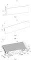
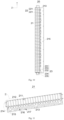
Fig. 1 is a structural diagram of a view of the battery in some embodiment of the present application. -
Fig. 2 is a structural diagram of another view of the battery inFig. 1 . -
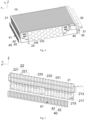
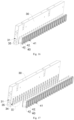
Fig. 3 is a structural diagram of the battery module in some embodiment of the present application. -
Fig. 4 is a structural diagram of the battery module inFig. 3 with a beam concealed. -
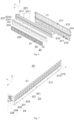
Fig. 5 is a disassembly diagram of the CCS assembly and the guiding structure inFig. 3 . -
Fig. 6 is another disassembly diagram of the CCS assembly and the guiding structure inFig. 3 . -
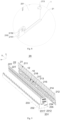
Fig. 7 is a structural diagram of the CCS assembly inFig. 3 . -
Fig. 8 is an enlarged view ofFig. 7 at I. -
Fig. 9 is a disassembly diagram of the CCS assembly inFig. 7 . -
Fig. 10 is a top view of the CCS assembly inFig. 7 . -
Fig. 11 is a structural diagram of the supporting frame inFig. 5 . -
Fig. 12 is an enlarged view ofFig. 11 at II. -
Fig. 13 is a perspective view of the guiding member inFig. 4 . -
Fig. 14 is a disassembly diagram of the guiding member inFig. 13 . -
Fig. 15 is a structural diagram of the guiding member inFig. 13 . -
Fig. 16 is a structural diagram of the beam and the guiding member inFig. 3 . -
Fig. 17 is a disassembly diagram of the beam and the guiding member inFig. 3 . -
Fig. 18 is an enlarged view ofFig. 17 at III. - The meanings of the attached markings are as follows:
100 battery module; 10 battery group; 11 battery; 111 positive electrode column; 112 negative electrode column; 113 explosion-proof valve; 20 CCS assembly; 21 supporting frame; 211 mounting hole; 212 buckle; 213 hot riveting post; 214 gap; 215 mounting structure; 2151 connection piece; 2152 snap-fit protrusion; 216 weight-loss hole; 217 escaping hole; 22 connection plate; 221 sub-plate; 23 collecting structure; 231 flexible printed circuit (FPC); 2311 first segment; 2312 second segment; 232 temperature collecting member; 233 electrical signal collecting member; 234 connector; 235 fuse protection structure; 30 beam; 31 pressure relief channel; 32 first stepped snap-fit position; 33 second stepped snap-fit position; 34 through-hole; 35 reinforcing rib; 40 guiding structure; 41 guiding channel; 42 guiding member; 421 tube body; 4211 first mounting platform; 4212 first groove; 4213 second mounting platform; 4214 snap-fit groove; 4215 main body; 422 first sealing ring; 423 second sealing ring. - The present application is described in further detail below in conjunction with the attached drawings.
- Referring to
Fig. 1 to Fig. 18 , provided in an embodiment of the present application is abattery module 100, including abattery group 10, aCCS assembly 20, abeam 30 and a guidingstructure 40. - Referring to
Fig. 3 andFig. 4 , thebattery group 10 includes a plurality ofbatteries 11, thebattery 11 including apositive electrode column 111 and anegative electrode column 112, thepositive electrode column 111 and thenegative electrode column 112 being provided oppositely in a length direction X of thebattery 11; aCCS assembly 20, provided on a side of thebattery group 10, electrically connected to thebattery group 10, used for collecting and transferring an electrical signal of thebattery group 10; abeam 30, provided opposite theCCS assembly 20, apressure relief channel 31 being provided within thebeam 30; and a guidingstructure 40, connected between thebattery group 10 and thebeam 30, the guidingstructure 40 being provided with a plurality of guidingchannels 41, each guidingchannel 41 being in communication with thepressure relief channel 31, each guidingchannel 41 being provided corresponding to an explosion-proof valve 113 of thebattery 11, wherein the guidingchannel 41 is used for guiding high-temperature gas and/or high-temperature fluid ejected from the explosion-proof valve 113 into thepressure relief channel 31 when thermal runaway occurs in thebattery 11. - By providing a guiding
structure 40 in thebattery module 100, the guidingstructure 40 is provided with a plurality of guidingchannels 41, each guidingchannel 41 being provided corresponding to an explosion-proof valve 113 of thebattery 11. When a thermal runaway occurs in abattery 11, the high-temperature gas or fluid ejected from the explosion-proof valve 113 may flow to thepressure relief channel 31 through the guidingstructure 40 and be dispersed through thebeam 30, avoiding splashing to the surroundingbatteries 11 and affecting the operating safety of theentire battery module 100. Therefore, the safety of theentire battery module 100 is improved by providing a guidingstructure 40. - It is to be noted that, referring to
Fig. 1 and Fig. 2 , thebattery 11 of the present embodiment is a blade battery, apositive electrode column 111 and anegative electrode column 112 of the blade battery being provided at opposite ends of thebattery 11 in a length direction X, the explosion-proof valve 113 and thepositive electrode column 111 are provided at the same end of thebattery 11. The length direction X of thebattery 11 is a width direction of thebattery module 100; the width direction Y of thebattery 11 is an alignment direction of thebattery 11; and the height direction Z of thebattery 11 is a height direction Z of thebattery module 100. Whenbatteries 11 are aligned as thebattery group 10, a large surface of onebattery 11 is provided towards a large surface of anotherbattery 11. That is, thebatteries 11 are provided side by side with each other along a thickness direction of thebatteries 11, and thepositive electrode columns 111 and thenegative electrode columns 112 of thebatteries 11 are aligned as alternating with each other. - Referring to
Fig. 4 to Fig. 6 , the guidingstructure 40 of the present embodiment penetrates theCCS assembly 20 when assembling. That is, theCCS assembly 20 is provided on a side of thebattery group 10 in the X direction when assembling. - Specifically, referring to
Fig. 4 to Fig. 12 , in order to facilitate the installation of theentire CCS assembly 20, and improve the mounting efficiency of theentire CCS assembly 20, theCCS assembly 20 includes a supportingframe 21, aconnection plate 22 and a collectingstructure 23, wherein the supportingframe 21 is provided on thebattery 11 in the height direction Z and supports a lateral side of thebattery group 10; theconnection plate 22 is mounted on the supportingframe 21 and electrically connected to thepositive electrode column 111 and thenegative electrode column 112 respectively; and the collectingstructure 23 is mounted on the supportingframe 21 and electrically connected to theconnection plate 22 and thebattery group 10 respectively, used for transferring the signal of thebattery group 10. By providing a supportingframe 21, the supportingframe 21 may provide support in a height direction Z of thebattery group 10, and the supportingframe 21 is a structure with a certain degree of hardness, which may facilitate support and installation between theconnection plate 22 and the collectingstructure 23. When installing theconnection plate 22 and the collectingstructure 23 on the supportingframe 21 to form aCCS assembly 20, theentire CCS assembly 20 may be clamped by mechanization, which achieves the mechanized installation between theCCS assembly 20 and thebattery group 10, thereby improving the assembling efficiency of theentire battery module 100. - Specifically, referring to
Fig. 5 to Fig. 7 ,Fig. 9 andFig. 10 , the collectingstructure 23 includes anFPC 231, a plurality oftemperature collecting members 232 electrically connected to theFPC 231, a plurality of electricalsignal collecting members 233 and aconnector 234. Theconnection plate 22 and theFPC 231 are provided sequentially from top to bottom in the height direction Z of thebattery 11. Theconnection plate 22 is used for achieving the electrical connection of thebattery group 10, specifically, electrically connected to thepositive electrode column 111 and thenegative electrode column 112 respectively, so as to achieve the series connection within thebattery group 10. The electricalsignal collecting member 233 is used for collecting the voltage signal of thebattery group 10, specifically, electrically connected between theconnection plate 22 and theFPC 231, so as to transfer the electrical signal to theFPC 231. Thetemperature collecting member 232 is used for collecting the temperature signal of thebattery group 10, specifically, electrically connected between thebattery 11 and theFPC 231, so as to transfer the temperature signal of thebattery group 10 to theFPC 231. In such a setup, the electrical connection with thebattery group 10 is achieved by theconnection plate 22; the voltage signal of thebattery group 10 transferred to theFPC 231 is achieved by the electricalsignal collecting member 233; the temperature signal of thebattery group 10 transferred to theFPC 231 is achieved by thetemperature collecting member 232; and finally the signal transferring with external structures is achieved by theconnector 234, for example, the signal transferring with the battery management system (BMS). - The guiding
structure 40 penetrating theCCS assembly 20 when assembling, specifically, penetrates the supportingframe 21 and theFPC 231. - Referring to
Fig. 5 to Fig. 7 ,Fig. 9 andFig. 10 , when electrically connecting theconnection plate 22 to thebattery group 10, theconnection plate 22 includes a plurality ofsub-plates 221, the supportingframe 21 being provided with a plurality of mountingholes 211, wherein each sub-plate 221 is mounted into each mountinghole 211, and each sub-plate 221 is connected to thepositive electrode column 111 and thenegative electrode column 112 of each twoadjacent batteries 11, so as to achieve the series connection of thebattery group 10 by theconnection plate 22 when mounting theCCS assembly 20 to thebattery group 10. That is, current flows from apositive electrode column 111 of abattery 11 to anegative electrode column 112, and flows from thenegative electrode column 112 to apositive electrode column 111 of anadjacent battery 11, so that a series connection within thebattery group 10 is achieved. - Specifically, each sub-plate 221 in the present embodiment is welded between a
positive electrode column 111 and anegative electrode column 112 of each twoadjacent batteries 11, which achieves electrical connection and also the conductivity of current. - The
connection plate 22 in the present embodiment is an aluminum plate, which may be a copper plate in the other embodiments, which is not limited hereby. - Specifically, referring to
Fig. 6 ,Fig. 9 ,Fig. 11 andFig. 12 , when mounting each sub-plate 221 to the supportingframe 21, the supportingframe 21 includes a plurality of mountingholes 211, and each sub-plate 221 is mounted into each mountinghole 211. By providing mountingholes 211 on the supportingframe 21, not only is the positioning of the sub-plate 211 is achieved, but also the installation of the sub-plate 211 is achieved. - It is to be understood that, since the sub-plate 211 is required to connect a
positive electrode column 111 and anegative electrode column 112 of each twoadjacent batteries 11, a shape of the mountinghole 211 is adapted to a shape of the sub-plate 211. For example, the sub-plate 221 is pentagon in shape, and the mountinghole 211 is also pentagon in shape, so that the sub-plate 221 is just correspondingly mounted into the mountinghole 211. - Referring to
Fig. 6 ,Fig. 9 ,Fig. 11 andFig. 12 , in an embodiment of the present application, when mounting the sub-plate 221 into the mountinghole 211 and before welding theconnection plate 22 to electrode columns, theconnection plate 22 is detachably mounted into the mountinghole 211. That is, each sub-plate 211 is correspondingly detachably mounted into each mountinghole 211, so that each position of the sub-plate 221 corresponding to thebattery 11 is adjusted into the position of the mountinghole 211. - Specifically, before welding each sub-plate 221 to electrode columns, the supporting
frame 21 is provided with abuckle 212, and thebuckle 212 is used for setting the sub-plate 221 into the mountinghole 211. That is, the sub-plate 221 is detachably mounted into the mountinghole 211 by snap-fitting. - Before welding each sub-plate 221 to electrode columns, in order to ensure the mounting stability of the sub-plate 221 mounted into the mounting
hole 211, the supportingframe 21 is provided with a plurality ofbuckles 212 corresponding to each position of the mountinghole 211, and a plurality ofbuckles 212 are separately provided on a plurality of side walls of the mountingholes 211, so as to fix the sub-plate 221 from multiple directions, thereby ensuring the stability of the sub-plate 221 mounted into the mountinghole 211. - Since the sub-plate 221 is snap-fitted into the mounting
hole 211 by thebuckle 212, when applied to theCCS assembly 20, theCCS assembly 20 is required to be mounted on a lateral side of thebattery group 10, so that errors may occur in the alignment installation of theCCS assembly 20 and thebattery group 10 when mounting theCCS assembly 20. In order to achieve the alignment of the position of theconnection plate 22 and columns, areserved gap 214 is provided between theconnection plate 22 and an internal wall of the mountinghole 211, so that the position of the sub-plate 221 may be adjusted to align each adjacent two electrode columns when mounting theCCS assembly 20 and thebattery group 10, and the sub-plate 221 is welded to two electrode columns respectively. In such a setup, since areserved gap 214 is provided between theconnection plate 22 and an internal wall of the mountinghole 211, errors may be adjusted, which facilitates the welding of corresponding region between the sub-plate 221 and electrode columns. - Referring to
Fig. 6, Fig. 7 andFig. 9 , in an embodiment of the present application, in order to accommodate thetemperature collecting member 232, the electricalsignal collecting member 233 and theconnector 234 to be mounted on theFPC 231 respectively, theFPC 231 includes afirst segment 2311 and asecond segment 2312 connected with each other, thefirst segment 2311 extending in an alignment direction of eachbattery 11, thesecond segment 2312 being provided on a side of thebattery 11 in a thickness direction, wherein thefirst segment 2311 is used for mounting the electricalsignal collecting member 233 and thetemperature collecting member 232, and thesecond segment 2312 is used for mounting theconnector 234. TheFPC 231 is provided by being divided into two segments, which achieves the electrical signal collecting of thebattery group 10 and achieves the signal transferring with external structures by theconnector 234, for example, the signal transferring with the battery management system (BMS). Also, since theFPC 231 is provided with certain flexibility, which may be bent and mounted on different sides of thebattery group 10, thereby facilitating the installation of each component within thebattery module 100. - It is to be understood that, the
first segment 2311 is provided on an end of a length direction X of thebattery 11, that is, extends in an alignment direction of thebattery group 10; thesecond segment 2312 is provided in a thickness direction Y of thebattery 11, that is, provided on a large-surface direction of thebattery 11, so that theconnector 234 mounted on thesecond segment 2312 may correspond the installation of the BMS. - Referring to
Fig. 7 ,Fig. 8 , andFig. 10 toFig. 12 , when mounting theFPC 231 to the supportingframe 21, theFPC 231 is connected to the supportingframe 21 by hot riveting, that is, the supportingframe 21 is provided with a hotriveting post 213, and theFPC 231 is mounted to the supportingframe 21 by the hotriveting post 213. In such a setup, the mounting stability of theFPC 231 and the supportingframe 21 is ensured. - The
temperature collecting member 232 in the present embodiment is a nickel sheet. Referring toFig. 6, Fig. 7 ,Fig. 9 andFig. 10 , when connecting the nickel sheet to the sub-plate 221, an amount of the nickel sheets corresponds to an amount of the sub-plates 221; each nickel sheet is connected to each sub-plate 221 correspondingly, so as to achieve the collecting of the voltage information of thebattery 11 by the nickel sheet. Specifically, when connecting the nickel sheet to theconnection plate 22, the supportingframe 21 is provided with agap 214, thegap 214 being in communication with the mountinghole 211, so as to connect the nickel sheet between theconnection plate 22 and theFPC 231. - Further, the
temperature collecting member 232 in the present embodiment is a temperature collecting chip. When mounting thetemperature collecting member 232, an amount of thetemperature collecting members 232 provided therein may less than the amount of the sub-plates 221. For example, in an alignment direction of thebattery 11, the opposite ends and the middle of thefirst segment 2311 of theFPC 231 are provided with atemperature collecting member 232 respectively. Onetemperature collecting member 232 achieves the temperature collecting of one region, so as to achieve the monitoring of the battery operating condition by BMS. - Furthermore, referring to
Fig. 4 ,Fig. 7 ,Fig. 9 andFig. 10 , in order to protect theentire CCS assembly 20 by overcurrent, the collectingstructure 23 also includes afuse protection structure 235, and thefuse protection structure 235 is connected to theFPC 231, specifically, connected to thesecond segment 2312 of theFPC 231. That is, thefuse protection structure 235 and theconnector 234 are collectively provided on thesecond segment 2312. TheCCS assembly 20 may fuse when the current in theCCS assembly 20 is too high, so as to protect thebattery group 10. - Specifically, the
fuse protection structure 235 in the present embodiment is a patch fuse, and the patch fuse is welded to thesecond segment 2312. Compared to printing fuses directly on theFPC 231, thefuse protection structure 235 in the present embodiment may be replaced after being damaged, so that theentire FPC 231 may be utilized once again, which provides with an advantage of reducing cost. - When mounting the guiding
structure 40 of the present embodiment, since theFPC 231 is provided below theconnection plate 22, the guidingstructure 40 penetrates the supportingframe 21 and theFPC 231, so as to achieve the connection between the guidingstructure 40 and the position of thebattery group 10 where the explosion-proof valve 113 is located, which achieves not only the connection between the guidingstructure 40 and thebattery group 10 but also the installation between the guidingstructure 40 and theCCS assembly 20. - Referring to
Fig. 6 to Fig. 8 ,Fig. 11 andFig. 12 , in order to facilitate the installation and formation of thebattery module 100, the supportingframe 21 of the present embodiment is provided with a mountingstructure 215, and the mountingstructure 215 is used for mounting a lateral cap. The mountingstructure 215 is integrally formed from the supportingframe 21, which facilitate the installation of the lateral cap of thebattery module 100, thereby improving the mounting efficiency of thebattery module 100. - Specifically, the mounting
structure 215 is provided for detachably connecting the lateral cap, which facilitates the installation of the lateral cap by a detachable connection, and also facilitates the maintenance of thebattery group 10 after subsequent dismounting of the lateral cap. Specifically, the mountingstructure 215 in the present embodiment includes aconnection piece 2151 and a snap-fit protrusion 2152 provided on theconnection piece 2151, theconnection piece 2151 extending to a top direction of thebattery group 10, the snap-fit protrusion 2152 being used for being snap-fitted to the lateral cap. - It is to be understood that, in order to ensure the mounting stability of the lateral cap, the supporting
frame 21 may be provided with a plurality of mountingstructures 215 in the alignment direction of thebattery group 10. In such a setup, the mounting stability of the lateral cap is ensured. - Specifically, the supporting
frame 21 in the present embodiment is a polymercomposite supporting frame 21 made of polycarbonate (PC) and acrylonitrile butadiene styrene (ABS). The polymercomposite support frame 21 made of ABS and PC provides the advantages of high anti-impact strength, good texture, durability and particularly high resistance to thermal deformation, so as to provide a certain level of supporting strength for mounting and fixing the collectingstructure 23 and theconnection plate 22. Also, compared to the prior art using PC film or hot-pressing film to hot press theconnection plate 22 and the collectingstructure 23, since the cooling formation of PC film or hot-pressing film requires a relatively long time, the supportingframe 21 prepared from the polymercomposite supporting frame 21 made of PC and ABS in the present embodiment may be formed quickly, which further improves the mounting efficiency of theentire CCS assembly 20. - Specifically, referring to
Fig. 9 ,Fig. 11 andFig. 12 , since the guidingstructure 40 penetrates the supportingframe 21 and is provided corresponding to the explosion-proof valve 113, in order to facilitate the installation of the guidingstructure 40, escapingholes 217 are provided on the positions of the supportingframe 21 corresponding to each explosion-proof valve 113 of the batteries. Also, the supportingframe 21 in the present embodiment is provided with a weight-loss hole 216, and the weight-loss hole 216 is provided for reducing weight of the supportingframe 21. - Specifically, when providing weight-
loss holes 216 and escapingholes 217 in the present embodiment, a weight-loss hole 216 and an escapinghole 217 are alternately provided so as to fully utilize the area of each two adjacent escapingholes 217 to provide weight-loss holes 216 to achieve weight reduction. - Referring to
Fig. 3 , in an embodiment of the present application, when mounting the guidingstructure 40, an end of the guidingstructure 40 is fixedly connected to thebattery group 10, and an opposite end of the guidingstructure 40 is detachably connected to abeam 30, so as to ensure the connection sealing between the guidingstructure 40 and thebattery group 10. By detachably connecting the opposite end of the guidingstructure 40 to thebeam 30, after assembling the guidingstructure 40 and thebattery group 10, it is convenient to connect thebeam 30 to the guidingstructure 40. - Specifically, when mounting the guiding
structure 40 to thebattery group 10 and thebeam 30, an end of the guidingstructure 40 is bonded to thebattery group 10, and an opposite end of the guidingstructure 40 is snap-fitted to thebeam 30. After mounting the guidingstructure 40 to thebattery group 10, thebeam 30 is tightly snap-fitted to the guidingstructure 40, so as to achieve the installation of theentire battery module 100. - Referring to
Fig. 5 ,Fig. 6 ,Fig. 16 and Fig. 17 , the guidingstructure 40 is provided with a plurality of guidingchannels 41, each guidingchannel 41 being in communication with thepressure relief channel 31, each guidingchannel 41 is provided corresponding to each explosion-proof valve 113 of abattery 11. In other embodiments, the guidingchannel 41 may be provided for including two sections. One section includes a plurality of sub-channels, and the sub-channel is provided corresponding to each explosion-proof valve 113 of abattery 11. Another section may aggregate the high-temperature and high-pressure gas and fluid flowing from the sub-channels and then forward them to thebeam 30, so that conductivity of high-temperature and high-pressure gas and fluid may also be achieved. - Corresponding to that each guiding
channel 41 is provided corresponding to each explosion-proof valve 113 of abattery 11, referring toFig. 5 ,Fig. 6 ,Fig. 16 and Fig. 17 , the guidingstructure 40 includes a plurality of independent guidingmember 42, each guidingmember 42 being formed each guidingchannel 41, each guidingmember 42 being provided corresponding to each explosion-proof valve 113 of abattery 11. In such a setup, by providing the guidingstructure 40 for including a plurality of independent guidingmember 42, each guidingmember 42 is formed individually. When connecting the guidingmember 42 to thebattery group 10, one guidingmember 42 is required to be aligned with one explosion-proof valve 113 of thebattery 11, so as to easily and accurately install each guidingmember 42 individually at the explosion-proof valve 113, which improves the mounting accuracy of the guidingmember 42. - In one embodiment, in order to improve the formation efficiency of the
entire guiding structure 40 and the mounting efficiency on thebattery group 10, the guidingstructure 40 may be provided for including a plurality of guidingmembers 42 and connecting ribs connected between a plurality of guidingmembers 42. The guidingmembers 42 are connected to be formed as a whole by connecting ribs. For example, theentire guiding structure 40 may be an integrally provided structure, so as to improve the production efficiency of theentire guiding structure 40. Alternatively, connecting ribs and guidingmembers 42 are structures formed individually, and then the guidingmembers 42 are mounted on the connecting ribs, so that the connecting ribs and the guidingmembers 42 are formed as one mounting unit. In this kind of implementation, when mounting theentire guiding structure 40, the guidingstructure 40 may be mounted on theentire battery group 10 all at once, which improves the mounting efficiency. Alternatively, in the other embodiment, when the guidingstructure 40 is provided as an integral structure, a plurality of guidingchannels 41 may be provided on anintegral guiding structure 40, and an amount of the guidingchannels 41 is identical to an amount of the explosion-proof valves 113, which may achieve that each explosion-proof valve 113 may relief pressure correspondingly. - A shape of the guiding
member 42 of the present embodiment is provided to be adapted to a shape of the explosion-proof valve 113, which may fully achieve the guiding of the electrolyte flowed from the explosion-proof valve 113. For example, when the explosion-proof valve 113 is provided in an oval shape, the guidingmember 42 is provided in an oval shape; when the explosion-proof valve 113 is circular, the guidingmember 42 is circular. In such a setup, the guidingmember 42 may be provided to enclose precisely around the explosion-proof valve 113 to allow the electrolyte to flow out, avoiding the electrolyte from flowing onto the cover of thebattery 11 when the cross-sectional area of the guidingmember 42 is greater than that of the explosion-proof valve 113; or it avoids the electrolyte from leaking and flowing onto anadj acent battery 11 when the cross-sectional area of theguide member 42 is less than that of the explosion-proof valve 113. - Specifically, referring to
Fig. 13 to Fig. 15 , when providing the guidingmember 42 in the present embodiment, in order to ensure the connecting sealing between the guidingmember 42, thebattery 11 and thebeam 30, the guidingmember 42 includes atube body 421, afirst sealing ring 422 and asecond sealing ring 423 provided at opposite ends of thetube body 421, thefirst sealing ring 422 being bonded to thebattery 11, thesecond sealing ring 423 being snap-fitted to thebeam 30. In such a setup, by providing thefirst sealing ring 422 and thesecond sealing ring 423, the connecting sealing of thetube body 421 at opposite ends with thebattery 11 and thebeam 30 is ensured respectively, which avoids high-temperature gas or fluid leaking out from the connection of thetube body 421. - Further, the end of the
tube body 421 connected to thebattery 11 and thefirst sealing ring 422 are collectively bonded to thebattery 11; when mounting thesecond sealing ring 423 on thebeam 30, an interference fit may be adopted to tightly snap-fit the opposite end of thetube body 421 to thebeam 30. - It is to be understood that, the
tube body 421 in the present embodiment is a metal tube. Metal materials are adopted to prepare the tube, which guarantees sufficient heat-resistance. For example, aluminum or aluminum alloy may be adopted, since the aluminum is at a low cost and resistant to high temperature, which may endure the high-temperature electrolyte. Thefirst sealing ring 422 and thesecond sealing ring 423 are also required to provide a high temperature resistance, for example, by using a nitrile butadiene rubber composite material or synthetic fiber rubber, which may not only achieve the sealing, but may also provide high temperature resistance. - Referring to
Fig. 13 to Fig. 15 , in order to facilitate the installation of thefirst sealing ring 422, thetube body 421 includes amain body 4215, afirst mounting platform 4211 and asecond mounting platform 4213 that are provided at opposite ends of themain body 4215; thefirst mounting platform 4211 protrudes from themain body 4215 along a perimeter of themain body 4215, thefirst sealing ring 422 being provided on thefirst mounting platform 4211. That is, by providing afirst mounting platform 4211 on an end of themain body 4215, a thickness of a tube wall of the end of themain body 4215 towards thebattery 11 is increased, which improves the structural strength, which may also facilitate to install thefirst sealing ring 422 on afirst mounting platform 4211 with thicker tube wall, so that thefirst mounting platform 4211 may provide support to thefirst sealing ring 422. - Specifically, when providing the
first sealing ring 422 on thefirst mounting platform 4211 in the present embodiment, afirst groove 4212 is provided on a side of thefirst mounting platform 4211 towards thebattery 11, and thefirst sealing ring 422 is snap-fitted into thefirst groove 4212. That is, by providing thefirst groove 4212, thefirst sealing ring 422 is snap-fitted into thefirst groove 4212, so as to achieve the installation of thefirst sealing ring 422. - Referring to
Fig. 13 to Fig. 15 , in order to facilitate installation of thesecond sealing ring 423, thesecond mounting platform 4213 protrudes from themain body 4215 along a perimeter of themain body 4215, thesecond mounting platform 4213 being used for mounting thesecond sealing ring 423. By providing thesecond mounting platform 4213, the structural strength of the end of the guidingmember 42 towards thebeam 30 is increased. Also, the provision of thesecond mounting platform 4213 facilitates thesecond sealing ring 423 to be connected to thetube body 421, so that thesecond mounting platform 4213 may provide support to thesecond sealing ring 423. - Specifically, the end of the
main body 4215 towards thebeam 30 in the present embodiment protrudes from thesecond mounting platform 4213, which facilitates the insertion with thebeam 30. When mounting thesecond sealing ring 423, thesecond sealing ring 423 is provided on an end surface of thesecond mounting platform 4213 towards thebeam 30. Correspondingly, since the end of themain body 4215 towards thebeam 30 protrudes from thesecond mounting platform 4213, when mounting the end of the guidingmember 42 towards thebeam 30, referring toFig. 17 andFig. 18 , thebeam 30 is provided with a first stepped snap-fit position 32 and a second stepped snap-fit position 33, the second stepped snap-fit position 33 surrounding an exterior of the first stepped snap-fit position 32, the first stepped snap-fit position 32 being used for being snap-fitted to an end of thetube body 421, the second stepped snap-fit position 33 being used for being snap-fitted to thesecond sealing ring 423, so as to achieve the detachable mount of the end of the guidingmember 42 towards thebeam 30. - The schematic installation diagram of the guiding
member 42 and thebeam 30 is shown inFig. 16 to Fig. 18 . Corresponding to the mounting position of the guidingmember 42, thebeam 30 is provided with a plurality of through-holes 34, the through-hole 34 being in communication with thepressure relief channel 31, each through-hole 34 being provided corresponding to each guidingmember 42. - Furthermore, referring to
Fig. 15 , in order to avoid a length of the guidingstructure 40 in the length direction X of thebattery 11 from being provided too long and affecting the occupied space of theentire battery module 100, in the present embodiment, a length L of the guidingmember 42 in the length direction X of thebattery 11 is provided in a range of 2-5cm. In such a setup, after connecting two ends of the guidingmember 42 to thebeam 30 and thebattery group 10 respectively, an appropriate spacing is also provided between thebeam 30 and thebattery group 10 to ensure the heat dissipation of thebattery group 10 through the spacing, without increasing the space occupied by theentire battery module 100 by an excessive amount. - For example, in some embodiments, a length L of the guiding
member 42 is provided with such as 2cm, 2.5cm, 3cm, 3.5cm, 4cm, and 5 cm, which is not repeated one by one hereby. Admittedly, in the other embodiments, the length of the guidingmember 42 may be provided with other dimensions with the range, which is not limited in the present embodiment. In a specific embodiment of the present application, the length L of the guidingmember 42 is provided with 3.0cm. It ensures that an appropriate spacing is provided between thebeam 30 and thebattery group 10 after the guidingmember 42 is mounted to thebeam 30 and thebattery 11, which ensures the heat dissipation of thebattery group 10 and that theentire battery module 100 does not occupy an excessive amount of space. - Furthermore, since the guiding
structure 40 penetrates the supportingframe 21, since each guidingmember 42 penetrates the supportingframe 21, in order to facilitate the installation of thetube body 421, a snap-fit groove 4214 is provided on a side wall of thefirst mounting platform 4211, and the supportingframe 21 is snap-fitted into the snap-fit groove 4214. By providing a snap-fit groove 4214, the connection of thetube body 421 and the supportingframe 21 is achieved. Specifically, the snap-fit groove 4214 is provided as a continuous full circle, so that thetube body 421 may provide sufficient contact area with the supportingframe 21 to ensure the connection strength of the supportingframe 21. - Specifically, when connecting the
tube body 421 to the supportingframe 21, before the supportingframe 21 is injection molded, thetube body 421 is placed in a corresponding position in the mold. When the supportingframe 21 is injection molded, the supportingframe 21 may be snap-fitted into the snap-fit groove 4214 of thetube body 421, thereby enabling the installation of thetube body 421 and the supportingframe 21. - Referring to
Fig. 3 ,Fig. 16 and Fig. 17 , in one embodiment of the present application, in order to reduce the weight of theentire battery module 100 and achieve the pressure relief effect of thebeam 30, apressure relief channel 31 extends in an alignment direction of thebattery 11 and penetrates thebeam 30. In such a setup, by providing a penetratingpressure relief channel 31, when thermal runaway occurs in thebattery 11, the high-temperature gas and fluid ejected from the explosion-proof valve 113 are guided by the guidingmember 42 into thebeam 30, so as to be flowed out from thebeam 30, thereby avoiding the risk of explosion. Also, by providing a penetratingpressure relief channel 31 in thebeam 30, it may not only sufficiently export high-temperature gas and fluid through thepressure relief channel 31, but also reduce the weight of thebeam 30. - Furthermore, since a penetrating
pressure relief channel 31 is provided in thebeam 30, in order to ensure the supporting strength of thebeam 30, thebeam 30 is provided with at least one reinforcingrib 35 in thepressure relief channel 31, the reinforcingrib 35 extending in an alignment direction of thebattery 11, i.e., provided in a horizontal direction. In such a setup, by providing a reinforcingrib 35 in thepressure relief channel 31, the supporting strength of theentire beam 30 is increased. - Further, the
beam 30 is provided with a plurality of reinforcingribs 35 in the present embodiment, a plurality of reinforcingribs 35 is separately provided in thebeam 30 in a height direction of thebattery 11, so as to increase the supporting strength of theentire beam 30. - It is to be understood that, since the
positive electrode column 111 and thenegative electrode column 112 of thebattery 11 are provided at opposite ends in a length direction X of thebattery 11, thebattery module 100 of the present embodiment includes twoCCS assemblies 20, two guidingstructures 40 and twobeams 30. Along the length direction X of thebattery 11, each of the opposite ends of thebattery group 10 is provided with aCCS assembly 20, a guidingstructure 40 and abeam 30, one guidingstructure 40 being correspondingly connected between one end of thebattery group 10 and onebeam 30, thereby forming acomplete battery module 100. - The
battery module 100 mentioned above: - (1) By providing a supporting
frame 21, the supportingframe 21 may provide support in a height direction of thebattery group 10, and the supportingframe 21 is a structure with a certain degree of hardness, which may facilitate support and installation of theCCS assembly 20. When installing theconnection plate 22, theFPC 231, and other electric connectors on the supportingframe 21 to form aCCS assembly 20, theentire CCS assembly 20 may be clamped by mechanization, which achieves the mechanized installation between theCCS assembly 20 and thebattery group 10, thereby improving the assembling efficiency of theentire battery module 100. - (1) By providing a guiding
structure 40, the guidingstructure 40 is provided with a plurality of guidingchannels 41, each guidingchannel 41 being provided corresponding to an explosion-proof valve 113 of thebattery 11. When a thermal runaway occurs in abattery 11, the high-temperature gas or fluid ejected from the explosion-proof valve 113 may flow to thepressure relief channel 31 through the guidingchannel 41 and be dispersed through thebeam 30, avoiding splashing to the surroundingbatteries 11 and affecting the operating safety of theentire battery module 100. Therefore, the safety of theentire battery module 100 is improved by providing a guidingstructure 40.
Claims (15)
- A battery module (100), comprising:a battery group (10), the battery group (10) comprising a plurality of batteries (11), the battery (11) comprising a positive electrode column (111) and a negative electrode column (112), the positive electrode column (111) and the negative electrode column (112) being provided oppositely in a length direction of the battery (11);a CCS assembly (20), provided on a side of the battery group (10), electrically connected to the battery group (10), used for collecting and transferring an electrical signal of the battery group (10);a beam (30), provided opposite the CCS assembly (20), a pressure relief channel (31) being provided within the beam (30); anda guiding structure(40), connected between the battery group (10) and the beam (30), the guiding structure (40) being provided with a plurality of guiding channels (41), each guiding channel (41) being in communication with the pressure relief channel (31), each guiding channel (41) being provided corresponding to an explosion-proof valve (113) of the battery (11), wherein the guiding channel (41) is configured for guiding high-temperature gas and/or high-temperature fluid ejected from the explosion-proof valve (113) into the pressure relief channel (31) when thermal runaway occurs in the battery (11).
- The battery module (100) according to claim 1, wherein the CCS assembly (20) comprises:a supporting frame (21), provided in a height direction of the battery (11), supported on a lateral side of the battery group (10);a connection plate (22), mounted on the supporting frame (21), electrically connected to the positive electrode column (111) and the negative electrode column (112) respectively; anda collecting structure (23), mounted on the supporting frame (21), electrically connected to the connection plate (22) and the battery group (10) respectively, the collecting structure (23) being used for transferring the electrical signal of the battery group (10).
- The battery module (100) according to claim 2, wherein the connection plate (22) comprises a plurality of sub-plates (221); the supporting frame (21) is provided with a plurality of mounting holes (211); each sub-plate (221) is mounted into each mounting hole (211); and a reserved gap (214) is provided between the sub-plate (221) and an interior wall of the mounting hole (211).
- The battery module (100) according to claim 2, wherein the connection plate (22) is snap-fitted to the supporting frame (21).
- The battery module (100) according to any one of claims 2-4, wherein the collecting structure (23) comprises an FPC (231), a connector (234) electrically connected to the FPC (231), a plurality of electrical signal collecting members (233) and a plurality of temperature collecting members (232), the electrical signal collecting member (233) being electrically connected to the connection plate (22), the temperature collecting member (232) being electrically connected to the battery (11);
the FPC (231) is connected to the supporting frame (21), comprising a first segment (2311) and a second segment (2312) connected with each other, the first segment (2311) extending in an alignment direction of each battery (11), the second segment (2312) being provided on a side of the battery (11) in a thickness direction, wherein the first segment (2311) is configured for mounting the electrical signal collecting member (233) and the temperature collecting member (232), and the second segment (2312) is configured for mounting the connector (234). - The battery module (100) according to claim 5, wherein the collecting structure (23) also comprises a fuse protection structure (235), and the fuse protection structure (235) is provided on the second segment (2312).
- The battery module (100) according to claim 6, wherein the fuse protection structure (235) is a patch fuse, and the patch fuse is welded to the second segment (2312).
- The battery module (100) according to any one of claims 2-4, wherein a mounting structure (215) is provided on the supporting frame (21); the mounting structure (215) is configured for mounting a lateral cap; and the mounting structure (215) is detachably connected to the lateral cap.
- The battery module (100) according to any one of claims 2-4, wherein the supporting frame (21) is a composite supporting frame (21) made of polycarbonate and acrylonitrile butadiene styrene.
- The battery module (100) according to claim 1, wherein an end of the guiding structure (40) is fixedly connected to the battery group (10), and an opposite end of the guiding structure (40) is detachably connected to a beam (30).
- The battery module (100) according to claim 1 or 10, wherein the guiding structure (40) comprises a plurality of independent guiding member (42), each guiding member (42) being formed each guiding channel (41), each guiding member (42) being provided corresponding to each explosion-proof valve (113).
- The battery module (100) according to claim 11, wherein the guiding member (42) comprises a tube body (421), a first sealing ring (422) and a second sealing ring (423) provided at opposite ends of the tube body (421), the first sealing ring (422) being bonded to the battery (11), the second sealing ring (423) being snap-fitted to the beam (30).
- The battery module (100) according to claim 12, wherein a length range of the guiding member (42) in a length direction of the battery (11) is 2-5cm.
- The battery module (100) according to claim 12, wherein the tube body (421) comprises a main body (4215), a first mounting platform (4211) and a second mounting platform (4213) that are provided at opposite ends of the main body (4215); the first mounting platform (4211) protrudes from the main body (4215) along a perimeter of the main body (4215), the first mounting platform (4211) being configured for mounting the first sealing ring (422); and the second mounting platform (4213) protrudes from the main body (4215) along a perimeter of the main body (4215), the second mounting platform (4213) being configured for mounting the second sealing ring (423).
- The battery module (100) according to any one of claims 1-4, wherein the pressure relief channel (31) extends in an alignment direction of the battery (11) and penetrates the beam (30); the beam (30) is provided with at least one reinforcing ribs (35) in the pressure relief channel (31); and the reinforcing rib (35) is provided in a horizontal direction.
Applications Claiming Priority (3)
| Application Number | Priority Date | Filing Date | Title |
|---|---|---|---|
| CN202321009800.0U CN219873949U (en) | 2023-04-27 | 2023-04-27 | CCS assembly and battery module |
| CN202321009570.8U CN219843114U (en) | 2023-04-27 | 2023-04-27 | CCS assembly and battery module |
| CN202321010119.8U CN219843106U (en) | 2023-04-27 | 2023-04-27 | battery module |
Publications (3)
| Publication Number | Publication Date |
|---|---|
| EP4456302A1 true EP4456302A1 (en) | 2024-10-30 |
| EP4456302C0 EP4456302C0 (en) | 2025-08-27 |
| EP4456302B1 EP4456302B1 (en) | 2025-08-27 |
Family
ID=88921067
Family Applications (1)
| Application Number | Title | Priority Date | Filing Date |
|---|---|---|---|
| EP23211114.6A Active EP4456302B1 (en) | 2023-04-27 | 2023-11-21 | Battery module |
Country Status (2)
| Country | Link |
|---|---|
| EP (1) | EP4456302B1 (en) |
| WO (1) | WO2024221544A1 (en) |
Citations (2)
| Publication number | Priority date | Publication date | Assignee | Title |
|---|---|---|---|---|
| WO2022203291A1 (en) * | 2021-03-22 | 2022-09-29 | 주식회사 엘지에너지솔루션 | Battery module and battery pack including same |
| CN115764149A (en) * | 2022-12-05 | 2023-03-07 | 广汽埃安新能源汽车股份有限公司 | Wire harness isolation board, battery module and electrical device |
Family Cites Families (8)
| Publication number | Priority date | Publication date | Assignee | Title |
|---|---|---|---|---|
| KR101537000B1 (en) * | 2008-12-22 | 2015-07-16 | 삼성에스디아이 주식회사 | Secondary battery module |
| WO2017143752A1 (en) * | 2016-02-25 | 2017-08-31 | 比亚迪股份有限公司 | Single-cell battery, battery module, power battery, and electric vehicle |
| CN207896195U (en) * | 2018-03-16 | 2018-09-21 | 宁德时代新能源科技股份有限公司 | Battery modules |
| CN111384324B (en) * | 2018-12-28 | 2021-08-06 | 宁德时代新能源科技股份有限公司 | battery module |
| JP2022517214A (en) * | 2019-01-09 | 2022-03-07 | ビーワイディー カンパニー リミテッド | Batteries, power battery packs and electric vehicles |
| CN214411453U (en) * | 2021-01-21 | 2021-10-15 | 江苏塔菲尔动力系统有限公司 | Battery module and battery package of solar heat protection diffusion |
| GB202203327D0 (en) * | 2022-03-10 | 2022-04-27 | Xerotech Ltd | An improved battery pack |
| CN218783170U (en) * | 2022-12-07 | 2023-03-31 | 远景动力技术(江苏)有限公司 | A battery pack housing assembly and battery pack |
-
2023
- 2023-07-07 WO PCT/CN2023/097981 patent/WO2024221544A1/en not_active Ceased
- 2023-11-21 EP EP23211114.6A patent/EP4456302B1/en active Active
Patent Citations (2)
| Publication number | Priority date | Publication date | Assignee | Title |
|---|---|---|---|---|
| WO2022203291A1 (en) * | 2021-03-22 | 2022-09-29 | 주식회사 엘지에너지솔루션 | Battery module and battery pack including same |
| CN115764149A (en) * | 2022-12-05 | 2023-03-07 | 广汽埃安新能源汽车股份有限公司 | Wire harness isolation board, battery module and electrical device |
Also Published As
| Publication number | Publication date |
|---|---|
| EP4456302C0 (en) | 2025-08-27 |
| WO2024221544A1 (en) | 2024-10-31 |
| EP4456302B1 (en) | 2025-08-27 |
Similar Documents
| Publication | Publication Date | Title |
|---|---|---|
| CN216597893U (en) | Laminate polymer battery core module and laminate polymer battery | |
| CN219801010U (en) | Battery pack with CCS assembly | |
| CN216793901U (en) | Soft-packaged battery cell module | |
| CN214477697U (en) | A battery module and battery pack | |
| EP3063806B1 (en) | Power battery module | |
| CN219843114U (en) | CCS assembly and battery module | |
| CN115000484B (en) | Fuel cell stack structure | |
| CN116937076A (en) | CCS assembly and battery module | |
| CN220692271U (en) | CCS assembly and battery module | |
| EP4456302B1 (en) | Battery module | |
| CN109216621A (en) | A kind of square electric core model group | |
| CN208522021U (en) | A kind of busbar connector and battery modules of battery modules | |
| CN223156115U (en) | A battery pack | |
| CN220914394U (en) | Battery top cover structure and battery | |
| CN116169436B (en) | Inner pole, battery core and battery module | |
| CN219843106U (en) | battery module | |
| CN223743843U (en) | A submersible energy storage cell module CCS structure | |
| CN219873949U (en) | CCS assembly and battery module | |
| CN222422410U (en) | Integrated busbar and battery pack | |
| CN223693203U (en) | A liquid-cooled battery module | |
| CN214625191U (en) | Large cylindrical lithium ion battery cover plate with liquid cooling | |
| CN219163485U (en) | Battery module and battery pack | |
| US20250070399A1 (en) | CCS Assembly and Battery Module | |
| CN223612469U (en) | A top cover assembly and a battery | |
| CN222826540U (en) | Battery square pre-installed structure and heavy energy storage device |
Legal Events
| Date | Code | Title | Description |
|---|---|---|---|
| PUAI | Public reference made under article 153(3) epc to a published international application that has entered the european phase |
Free format text: ORIGINAL CODE: 0009012 |
|
| STAA | Information on the status of an ep patent application or granted ep patent |
Free format text: STATUS: REQUEST FOR EXAMINATION WAS MADE |
|
| 17P | Request for examination filed |
Effective date: 20231121 |
|
| AK | Designated contracting states |
Kind code of ref document: A1 Designated state(s): AL AT BE BG CH CY CZ DE DK EE ES FI FR GB GR HR HU IE IS IT LI LT LU LV MC ME MK MT NL NO PL PT RO RS SE SI SK SM TR |
|
| GRAP | Despatch of communication of intention to grant a patent |
Free format text: ORIGINAL CODE: EPIDOSNIGR1 |
|
| STAA | Information on the status of an ep patent application or granted ep patent |
Free format text: STATUS: GRANT OF PATENT IS INTENDED |
|
| INTG | Intention to grant announced |
Effective date: 20250318 |
|
| GRAS | Grant fee paid |
Free format text: ORIGINAL CODE: EPIDOSNIGR3 |
|
| GRAA | (expected) grant |
Free format text: ORIGINAL CODE: 0009210 |
|
| STAA | Information on the status of an ep patent application or granted ep patent |
Free format text: STATUS: THE PATENT HAS BEEN GRANTED |
|
| AK | Designated contracting states |
Kind code of ref document: B1 Designated state(s): AL AT BE BG CH CY CZ DE DK EE ES FI FR GB GR HR HU IE IS IT LI LT LU LV MC ME MK MT NL NO PL PT RO RS SE SI SK SM TR |
|
| REG | Reference to a national code |
Ref country code: CH Ref legal event code: EP |
|
| REG | Reference to a national code |
Ref country code: DE Ref legal event code: R096 Ref document number: 602023006103 Country of ref document: DE |
|
| REG | Reference to a national code |
Ref country code: IE Ref legal event code: FG4D |
|
| U01 | Request for unitary effect filed |
Effective date: 20250923 |
|
| U07 | Unitary effect registered |
Designated state(s): AT BE BG DE DK EE FI FR IT LT LU LV MT NL PT RO SE SI Effective date: 20251001 |
|
| PG25 | Lapsed in a contracting state [announced via postgrant information from national office to epo] |
Ref country code: IS Free format text: LAPSE BECAUSE OF FAILURE TO SUBMIT A TRANSLATION OF THE DESCRIPTION OR TO PAY THE FEE WITHIN THE PRESCRIBED TIME-LIMIT Effective date: 20251227 |
|
| PG25 | Lapsed in a contracting state [announced via postgrant information from national office to epo] |
Ref country code: NO Free format text: LAPSE BECAUSE OF FAILURE TO SUBMIT A TRANSLATION OF THE DESCRIPTION OR TO PAY THE FEE WITHIN THE PRESCRIBED TIME-LIMIT Effective date: 20251127 |
|
| PG25 | Lapsed in a contracting state [announced via postgrant information from national office to epo] |
Ref country code: HR Free format text: LAPSE BECAUSE OF FAILURE TO SUBMIT A TRANSLATION OF THE DESCRIPTION OR TO PAY THE FEE WITHIN THE PRESCRIBED TIME-LIMIT Effective date: 20250827 |
|
| PG25 | Lapsed in a contracting state [announced via postgrant information from national office to epo] |
Ref country code: GR Free format text: LAPSE BECAUSE OF FAILURE TO SUBMIT A TRANSLATION OF THE DESCRIPTION OR TO PAY THE FEE WITHIN THE PRESCRIBED TIME-LIMIT Effective date: 20251128 |
|
| PG25 | Lapsed in a contracting state [announced via postgrant information from national office to epo] |
Ref country code: PL Free format text: LAPSE BECAUSE OF FAILURE TO SUBMIT A TRANSLATION OF THE DESCRIPTION OR TO PAY THE FEE WITHIN THE PRESCRIBED TIME-LIMIT Effective date: 20250827 |
|
| PG25 | Lapsed in a contracting state [announced via postgrant information from national office to epo] |
Ref country code: RS Free format text: LAPSE BECAUSE OF FAILURE TO SUBMIT A TRANSLATION OF THE DESCRIPTION OR TO PAY THE FEE WITHIN THE PRESCRIBED TIME-LIMIT Effective date: 20251127 |
|
| PG25 | Lapsed in a contracting state [announced via postgrant information from national office to epo] |
Ref country code: ES Free format text: LAPSE BECAUSE OF FAILURE TO SUBMIT A TRANSLATION OF THE DESCRIPTION OR TO PAY THE FEE WITHIN THE PRESCRIBED TIME-LIMIT Effective date: 20250827 |
|
| PG25 | Lapsed in a contracting state [announced via postgrant information from national office to epo] |
Ref country code: SM Free format text: LAPSE BECAUSE OF FAILURE TO SUBMIT A TRANSLATION OF THE DESCRIPTION OR TO PAY THE FEE WITHIN THE PRESCRIBED TIME-LIMIT Effective date: 20250827 |
|
| U21 | Renewal fee for the european patent with unitary effect paid with additional fee |
Year of fee payment: 3 Effective date: 20260310 |
|
| PG25 | Lapsed in a contracting state [announced via postgrant information from national office to epo] |
Ref country code: CZ Free format text: LAPSE BECAUSE OF FAILURE TO SUBMIT A TRANSLATION OF THE DESCRIPTION OR TO PAY THE FEE WITHIN THE PRESCRIBED TIME-LIMIT Effective date: 20250827 |
|
| PG25 | Lapsed in a contracting state [announced via postgrant information from national office to epo] |
Ref country code: SK Free format text: LAPSE BECAUSE OF FAILURE TO SUBMIT A TRANSLATION OF THE DESCRIPTION OR TO PAY THE FEE WITHIN THE PRESCRIBED TIME-LIMIT Effective date: 20250827 |