EP4456296A1 - Battery rack having a drainage structure and energy storage system including the same - Google Patents
Battery rack having a drainage structure and energy storage system including the same Download PDFInfo
- Publication number
- EP4456296A1 EP4456296A1 EP23799628.5A EP23799628A EP4456296A1 EP 4456296 A1 EP4456296 A1 EP 4456296A1 EP 23799628 A EP23799628 A EP 23799628A EP 4456296 A1 EP4456296 A1 EP 4456296A1
- Authority
- EP
- European Patent Office
- Prior art keywords
- battery
- drain guide
- guide unit
- rack
- rack case
- Prior art date
- Legal status (The legal status is an assumption and is not a legal conclusion. Google has not performed a legal analysis and makes no representation as to the accuracy of the status listed.)
- Pending
Links
Images



Classifications
-
- H—ELECTRICITY
- H01—ELECTRIC ELEMENTS
- H01M—PROCESSES OR MEANS, e.g. BATTERIES, FOR THE DIRECT CONVERSION OF CHEMICAL ENERGY INTO ELECTRICAL ENERGY
- H01M50/00—Constructional details or processes of manufacture of the non-active parts of electrochemical cells other than fuel cells, e.g. hybrid cells
- H01M50/60—Arrangements or processes for filling or topping-up with liquids; Arrangements or processes for draining liquids from casings
- H01M50/691—Arrangements or processes for draining liquids from casings; Cleaning battery or cell casings
-
- H—ELECTRICITY
- H01—ELECTRIC ELEMENTS
- H01M—PROCESSES OR MEANS, e.g. BATTERIES, FOR THE DIRECT CONVERSION OF CHEMICAL ENERGY INTO ELECTRICAL ENERGY
- H01M50/00—Constructional details or processes of manufacture of the non-active parts of electrochemical cells other than fuel cells, e.g. hybrid cells
- H01M50/20—Mountings; Secondary casings or frames; Racks, modules or packs; Suspension devices; Shock absorbers; Transport or carrying devices; Holders
- H01M50/204—Racks, modules or packs for multiple batteries or multiple cells
-
- A—HUMAN NECESSITIES
- A62—LIFE-SAVING; FIRE-FIGHTING
- A62C—FIRE-FIGHTING
- A62C3/00—Fire prevention, containment or extinguishing specially adapted for particular objects or places
- A62C3/16—Fire prevention, containment or extinguishing specially adapted for particular objects or places in electrical installations, e.g. cableways
-
- H—ELECTRICITY
- H01—ELECTRIC ELEMENTS
- H01M—PROCESSES OR MEANS, e.g. BATTERIES, FOR THE DIRECT CONVERSION OF CHEMICAL ENERGY INTO ELECTRICAL ENERGY
- H01M10/00—Secondary cells; Manufacture thereof
- H01M10/42—Methods or arrangements for servicing or maintenance of secondary cells or secondary half-cells
-
- H—ELECTRICITY
- H01—ELECTRIC ELEMENTS
- H01M—PROCESSES OR MEANS, e.g. BATTERIES, FOR THE DIRECT CONVERSION OF CHEMICAL ENERGY INTO ELECTRICAL ENERGY
- H01M10/00—Secondary cells; Manufacture thereof
- H01M10/42—Methods or arrangements for servicing or maintenance of secondary cells or secondary half-cells
- H01M10/4207—Methods or arrangements for servicing or maintenance of secondary cells or secondary half-cells for several batteries or cells simultaneously or sequentially
-
- H—ELECTRICITY
- H01—ELECTRIC ELEMENTS
- H01M—PROCESSES OR MEANS, e.g. BATTERIES, FOR THE DIRECT CONVERSION OF CHEMICAL ENERGY INTO ELECTRICAL ENERGY
- H01M10/00—Secondary cells; Manufacture thereof
- H01M10/60—Heating or cooling; Temperature control
- H01M10/61—Types of temperature control
- H01M10/613—Cooling or keeping cold
-
- H—ELECTRICITY
- H01—ELECTRIC ELEMENTS
- H01M—PROCESSES OR MEANS, e.g. BATTERIES, FOR THE DIRECT CONVERSION OF CHEMICAL ENERGY INTO ELECTRICAL ENERGY
- H01M10/00—Secondary cells; Manufacture thereof
- H01M10/60—Heating or cooling; Temperature control
- H01M10/62—Heating or cooling; Temperature control specially adapted for specific applications
- H01M10/627—Stationary installations, e.g. power plant buffering or backup power supplies
-
- H—ELECTRICITY
- H01—ELECTRIC ELEMENTS
- H01M—PROCESSES OR MEANS, e.g. BATTERIES, FOR THE DIRECT CONVERSION OF CHEMICAL ENERGY INTO ELECTRICAL ENERGY
- H01M50/00—Constructional details or processes of manufacture of the non-active parts of electrochemical cells other than fuel cells, e.g. hybrid cells
- H01M50/20—Mountings; Secondary casings or frames; Racks, modules or packs; Suspension devices; Shock absorbers; Transport or carrying devices; Holders
- H01M50/204—Racks, modules or packs for multiple batteries or multiple cells
- H01M50/207—Racks, modules or packs for multiple batteries or multiple cells characterised by their shape
- H01M50/209—Racks, modules or packs for multiple batteries or multiple cells characterised by their shape adapted for prismatic or rectangular cells
-
- H—ELECTRICITY
- H01—ELECTRIC ELEMENTS
- H01M—PROCESSES OR MEANS, e.g. BATTERIES, FOR THE DIRECT CONVERSION OF CHEMICAL ENERGY INTO ELECTRICAL ENERGY
- H01M50/00—Constructional details or processes of manufacture of the non-active parts of electrochemical cells other than fuel cells, e.g. hybrid cells
- H01M50/20—Mountings; Secondary casings or frames; Racks, modules or packs; Suspension devices; Shock absorbers; Transport or carrying devices; Holders
- H01M50/204—Racks, modules or packs for multiple batteries or multiple cells
- H01M50/207—Racks, modules or packs for multiple batteries or multiple cells characterised by their shape
- H01M50/211—Racks, modules or packs for multiple batteries or multiple cells characterised by their shape adapted for pouch cells
-
- H—ELECTRICITY
- H01—ELECTRIC ELEMENTS
- H01M—PROCESSES OR MEANS, e.g. BATTERIES, FOR THE DIRECT CONVERSION OF CHEMICAL ENERGY INTO ELECTRICAL ENERGY
- H01M50/00—Constructional details or processes of manufacture of the non-active parts of electrochemical cells other than fuel cells, e.g. hybrid cells
- H01M50/20—Mountings; Secondary casings or frames; Racks, modules or packs; Suspension devices; Shock absorbers; Transport or carrying devices; Holders
- H01M50/251—Mountings; Secondary casings or frames; Racks, modules or packs; Suspension devices; Shock absorbers; Transport or carrying devices; Holders specially adapted for stationary devices, e.g. power plant buffering or backup power supplies
-
- H—ELECTRICITY
- H01—ELECTRIC ELEMENTS
- H01M—PROCESSES OR MEANS, e.g. BATTERIES, FOR THE DIRECT CONVERSION OF CHEMICAL ENERGY INTO ELECTRICAL ENERGY
- H01M2200/00—Safety devices for primary or secondary batteries
- H01M2200/10—Temperature sensitive devices
-
- H—ELECTRICITY
- H01—ELECTRIC ELEMENTS
- H01M—PROCESSES OR MEANS, e.g. BATTERIES, FOR THE DIRECT CONVERSION OF CHEMICAL ENERGY INTO ELECTRICAL ENERGY
- H01M2220/00—Batteries for particular applications
- H01M2220/10—Batteries in stationary systems, e.g. emergency power source in plant
-
- Y—GENERAL TAGGING OF NEW TECHNOLOGICAL DEVELOPMENTS; GENERAL TAGGING OF CROSS-SECTIONAL TECHNOLOGIES SPANNING OVER SEVERAL SECTIONS OF THE IPC; TECHNICAL SUBJECTS COVERED BY FORMER USPC CROSS-REFERENCE ART COLLECTIONS [XRACs] AND DIGESTS
- Y02—TECHNOLOGIES OR APPLICATIONS FOR MITIGATION OR ADAPTATION AGAINST CLIMATE CHANGE
- Y02E—REDUCTION OF GREENHOUSE GAS [GHG] EMISSIONS, RELATED TO ENERGY GENERATION, TRANSMISSION OR DISTRIBUTION
- Y02E60/00—Enabling technologies; Technologies with a potential or indirect contribution to GHG emissions mitigation
- Y02E60/10—Energy storage using batteries
Definitions
- the present disclosure relates to a battery rack and an energy storage system including the same, and more particularly, to a battery rack with a drainage structure for preventing a fire fighting water fed into a battery module in which a thermal event occurred from entering other adjacent battery modules and an energy storage system including the same.
- Secondary batteries widely used at present include lithium ion batteries, lithium polymer batteries, nickel cadmium batteries, nickel hydrogen batteries, nickel zinc batteries or the like.
- lithium secondary batteries have little or no memory effect, and thus they are gaining more attention than nickel-based secondary batteries for their advantages that recharging can be done whenever it is convenient, the self-discharge rate is very low and the energy density is high.
- lithium secondary batteries may be classified into can type secondary batteries in which an electrode assembly is included in a metal can and pouch type secondary batteries in which an electrode assembly is included in a pouch of an aluminum laminate sheet according to the shape of outer packaging.
- a secondary battery may be used alone, but in general, since the voltage of a secondary battery is about 2.5V to 4.5V, when a higher output voltage is required, a plurality of secondary batteries may be connected in series and/or in parallel to form a battery module. Additionally, a battery module may be used alone, or two or more battery modules may be electrically connected in series and/or in parallel to form a device of higher level such as a battery rack or a battery pack.
- an energy storage system including a plurality of battery racks to store power during off-peak hours and use the stored power during peak hours.
- an industrial energy storage system includes battery racks, each including a rack case and a plurality of battery modules which is received in the rack case along the vertical direction, and a container accommodating the battery racks, an air conditioning device for managing the temperature of the battery racks and a fire extinguishing device for fire prevention or the like.
- a fire extinguishing system is introduced into the energy storage system, the fire extinguishing system designed to, in the event of thermal runaway of battery cells in a specific battery module mounted in a battery rack, feed a fire fighting water into the specific battery module before heat propagation to the other battery modules in order to suppress the fire.
- the conventional battery rack includes the rack case in the shape of a frame with open upper, lower, left and right sides and battery modules stacked in multistep arrangement in the rack case without a proper drainage structure, and thus after the fire fighting water is fed into the battery module by the fire extinguishing system, when leakage of the fire fighting water occurs in the corresponding battery module, the fire fighting water may easily enter the other adjacent battery module. In this case, the other adjacent battery modules may suffer flood damage, causing loss, for example, even normal battery modules may spoil.
- the present disclosure is designed to solve the above-described problem, and therefore the present disclosure is directed to providing a battery rack having a drainage structure for preventing a fire fighting water fed into a battery module in which a thermal event occurred from entering other adjacent battery modules and an energy storage system including the same.
- a battery rack may include a plurality of battery modules; a rack case having receiving portions, each configured to insert and receive each of the plurality of battery modules at each predetermined height, and having a structure in which upper and lower sides and left and right sides are closed except front and rear sides; a fire fighting water supply pipe connected to each of the battery modules received in the receiving portions to supply a fire fighting water when a fire occurs; and a drain guide unit disposed on at least one surface of a front outer surface or a rear outer surface of the rack case, and configured to guide drainage of the fire fighting water to cause the fire fighting water coming out of the battery module after having been fed into the battery module to be dropped down to a location spaced a predetermined distance apart from the outer surface of the rack case.
- the drain guide unit may be coupled to the outer surface of the rack case at a location which is lower than an upper battery module of every two battery modules vertically adjacent to each other and higher than a lower battery module.
- the drain guide unit may protrude from the outer surface of the rack case so that a predetermined angle is formed between a plate surface of the drain guide unit and the outer surface of the rack case.
- the drain guide unit ay be rotatably coupled to the outer surface of the rack case.
- the drain guide unit may be configured to cover the receiving portion located on the drain guide unit when it is rotated upwards.
- the drain guide unit may be configured to open the receiving portion located on the drain guide unit when it is rotated downwards.
- the drain guide unit may include a drain guide plate of a plate shape hinged to the outer surface of the rack case; and a stopper configured to limit rotation of the drain guide plate so that the drain guide plate is at a preset angle with respect to the outer surface of the rack case.
- the stopper may be in a shape of a protrusion which protrudes from an edge area of the drain guide plate close to a rotation axis so as to come in contact with the outer surface of the rack case at the preset angle.
- the drain guide unit may further include a magnet at an edge area opposite a rotation axis of the drain guide plate, to allow the drain guide plate rotated upwards to be fixed in parallel to the outer surface of the rack case.
- the drain guide unit may include a first drain guide unit disposed on a front outer surface of the rack case; and a second drain guide unit disposed on a rear outer surface of the rack case.
- the receiving portion may have a narrower horizontal width of a rear open end than a front open side, and the fire fighting water supply pipe may be connected to each battery module through the rear outer surface of the rack case.
- the first drain guide unit may be provided in a size to cover a front open end of each receiving portion, and the second drain guide unit may be provided in a size to cover a rear open end of each receiving portion.
- the battery module may include a fan in a front surface of a module housing and an air conditioning hole in a rear surface of the module housing, and may be inserted into the receiving portion through the rear open end of the receiving portion such that the air conditioning hole is exposed.
- a portion of the rear surface of the module housing below the air conditioning hole may be closed by the rear outer surface of the rack case.
- an energy storage system including at least one battery rack described above.
- the present disclosure it may be possible to prevent the fire fighting water fed into any battery module of the battery rack in which a thermal event occurred from entering the other adjacent battery modules in the event of overflow and leakage of the fire fighting water. Accordingly, when the fire fighting water is fed into the battery rack, the other battery modules except the battery module in which the thermal event occurred may avoid flood damage.
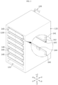
- FIG. 2 is a perspective view schematically showing a battery rack according to an embodiment of the present disclosure before insertion of a battery module
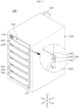
- FIG. 3 is a perspective view schematically showing the battery rack according to an embodiment of the present disclosure after insertion of a battery module
- FIG. 4 is a front view of the battery rack of FIG. 3
- FIG. 5 is a rear view of the battery rack of FIG. 3 .
- the battery rack 100 may include a plurality of battery modules 110, a rack case 120, a fire fighting water supply pipe 130 and a drain guide unit 140.
- Each battery module 110 may include secondary batteries 111 and a module housing 112 accommodating the secondary batteries 111 and may be configured to store and release electrical energy.
- the secondary batteries 111 may be connected in series and/or in parallel within the module housing 112 according to the required capacity and output for the battery module 110.
- each battery module 110 may include a cooling fan 114 and an air conditioning hole 116 to dissipate heat generated during charging/discharging.
- the cooling fan 114 may be disposed in the front surface portion of the module housing 112 and the air conditioning hole 116 may be disposed in the rear surface portion of the module housing 112.
- the cooling fan 114 operates, after the outside air enters the battery module 110 through the air conditioning hole 116 in the rear surface portion of the battery module 110 and absorbs heat of the secondary batteries 111, the air may be forced out through the cooling fan 114 in the front surface portion of the battery module 110.
- the cooling fan 114 may be disposed in the rear surface of the battery module 110 and the air conditioning hole 116 may be disposed in the front surface of the battery module 110.
- each battery module 110 may be configured to directly feed the fire fighting water into the module housing 112 in case of a situation in which a thermal event such as thermal runaway, fire, explosion or the like occurs in the secondary battery 111 during charging/discharging.
- the fire fighting water supply pipe 130 is connected to the rear surface of each battery module 110, and when a thermal event occurs, the fire fighting water may be fed into the corresponding battery module 110. Its detailed description will be provided below.
- the rack case 120 may be approximately cuboidal in shape to insert and receive each of the plurality of battery modules 110 at each predetermined height. Additionally, the rack case 120 may be made of a stiff material, preferably, a metallic or non-metallic material having high mechanical strength to protect the battery modules 110 from impacts or vibration.
- the rack case 120 may include a plurality of receiving portions 121 along the vertical direction and may be configured to receive each battery module 110 in each receiving portion 121.
- Each receiving portion 121 may have a structure in which the upper, lower, left and right sides (+Z,-Z,-X,+X) are closed except the front side (-Y) and the rear side (+Y). That is, as opposed to the conventional rack case 1 (see FIG. 1 ) having a structure in which front, rear, upper, lower, left and right sides are open, the rack case 120 according to the present disclosure has a structure in which upper, lower, left and right sides are closed.
- the rack case 120 may be configured such that the upper, lower, left and right sides of each receiving portion 121 are closed and the front and rear sides are open to prevent flood damage of the other battery modules 110 and guide the drainage of the fire fighting water in the frontward or rearward direction when suppressing fire using the fire fighting water.
- the drain guide unit 140 may be disposed on at least one side of the front outer surface or the rear outer surface of the rack case 120 to cause the fire fighting water to be dropped down to a location spaced a predetermined distance apart from the outer surface of the rack case 120 when the fire fighting water coming out of the battery module 110 moves to the front side or rear side of the rack case 120 and falls out of the rack case 120.
- the drain guide unit 140 may protrude from the outer surface of the rack case 120 with inclination of a predetermined angle so that the predetermined angle is formed between the plate surface the drain guide unit 140 and the outer surface of the rack case.
- the drain guide unit 140 may protrude outwards with inclination of the predetermined angle on the basis of the outer surface of the rack case 120 perpendicular to the ground, and may act as eaves to protect and cover the battery module 110 in the underlying receiving portion 121 from the fire fighting water falling down from above.
- the drain guide unit 140 may play a role in preventing venting gas to flames from the battery module 110 from spreading to the battery module 110 located on or below in the event of a fire in the battery module 110.
- the drain guide unit 140 may be coupled to the outer surface of the rack case 120 at a location that is lower than the upper battery module 110 of every two battery modules 110 vertically adjacent to each other and higher than the lower battery module 110. That is, the plurality of drain guide units 140 may be arranged along the vertical direction, and may be coupled to the outer surface of the rack case 120 at each height between the upper battery module 110 and the lower battery module 110.
- the battery rack 100 includes seven battery modules 110 stacked in the vertical direction, and in this case, six drain guide units 140 may be coupled to the front outer surface 120F of the rack case 120, and another six drain guide units 140 may be coupled to the rear outer surface 120R of the rack case 120. Then, when the fire fighting water is fed in response to a thermal event in any of the seven battery modules 110, the other battery modules 110 except the corresponding battery module 110 may avoid flood damage caused by the fire fighting water.
- the drain guide unit 140 is configured to partially cover the front side of a front open end of the underlying receiving portion 121.
- the battery module 110 when the battery module 110 while placed in horizontal condition is directly inserted into the receiving portion 121, the battery module 110 cannot be inserted into the receiving portion 121 due to interference with the drain guide unit 140.
- the eaves of the drain guide unit 140 may be short in length to avoid interference with the drain guide unit 140 when inserting the battery module 110 into the receiving portion 121.
- the eaves of the drain guide unit 140 is long in length to drain the fire fighting water by the drain guide unit 140 more effectively.
- the battery rack 100 includes the drain guide unit 140 of rotatable type.
- the drain guide unit 140 may be rotated and attached to the outer surface of the rack case 120.
- the drain guide unit 140 is configured to rotate in the upward direction to cover the receiving portion 121 located on the corresponding drain guide unit 140.
- the drain guide unit 140 may be configured to rotate in the downward direction to open the receiving portion 121 located on the corresponding drain guide unit 140.
- the grain guide unit 140 rotated in the downward direction may act as eaves for the underlying receiving portion 121 as shown in FIG. 3 .
- the battery module 110 when receiving the battery module 110 in the rack case 120, for example, as shown in FIG. 2 , the battery module 110 is inserted into the bottommost receiving portion 121 of the rack case 120, and the drain guide unit 140 located immediately on the bottommost receiving portion 121 is rotated in the downward direction by the predetermined angle.
- the second receiving portion 121 of the rack case 120 from the bottom is open.
- the battery module 110 is inserted into the open second receiving portion 121.
- the battery modules 110 are inserted in a sequential order from the bottommost receiving portion 121 of the rack case 120 to the topmost receiving portion 121.
- the battery modules 110 are received in the rack case 120, and as shown in FIG. 3 , each drain guide unit 140 protrudes from the outer surface of the rack case 120 at the predetermined angle between the drain guide unit 140 and the outer surface of the rack case 120.
- the drain guide unit 140 may include a drain guide plate 141 and a stopper 142.
- the drain guide plate 141 may be in the shape of a plate that is hinged 143 to the outer surface of the rack case 120.
- the drain guide plate 141 may be provided in a size to cover the receiving portion 121 located on the drain guide plate 141 when it is rotated upwards and attached to the outer surface of the rack case 120 and may be made of any stiff material, for example, plastics or metals.
- the drain guide plate 141 may have a magnet 144 in the opposite edge area to the hinged 143 edge area as shown in the enlarged diagram of FIG. 2 . The magnet 144 may be used to rotate the drain guide plate 141 upwards and fix it to the outer surface of the rack case 120.
- the drain guide unit 140 has a structure in which the stopper 142 is incorporated into the drain guide plate 141 so that when the drain guide plate 141 rotates in the downward direction (-Z direction), the rotation may stop at the predetermined angle.
- the drain guide plate 141 when the drain guide plate 141 is at the preset angle ⁇ with respect to the outer surface of the rack case 120, one surface of the stopper 142 comes into contact with the outer surface of the rack case, thereby limiting the rotation of the drain guide plate 141.
- the preset angle ⁇ may be, for example, determined in a range between 30° and 60°. Accordingly, the drain guide unit 140 may act as eaves for the underlying receiving portion 121.
- the stopper 142 may be in the shape of a protrusion that protrudes from the edge area of the drain guide plate 141 close to the rotation axis so as to contact the outer surface of the rack case 120 at the preset angle ⁇ as shown in the enlarged section of FIG. 3 .
- the protrusion may be preferably in the shape of an approximately right-angled triangle in cross section and extended to a length corresponding to the horizontal ( ⁇ X direction) width of the drain guide plate 141.
- the stopper 142 By the stopper 142, the drain guide plate 141 rotates in the downward direction, and stops when the hypotenuse of the right-angled triangle comes into contact with the outer surface of the rack case 120. Accordingly, the drain guide plate 141 may form the eave structure that protrudes with inclination of the preset angle with respect to the outer surface of the rack case 120.
- the drain guide unit 140 includes a first drain guide unit 140A on the front outer surface 120F of the rack case 120 as shown in FIG. 4 , and a second drain guide unit 140B on the rear outer surface 120R of the rack case 120 as shown in FIG. 5 .
- the first drain guide unit 140A may be provided in a size to cover the front open end of each receiving portion 121
- the second drain guide unit 140B may be provided in a size to cover the rear open end of each receiving portion 121.
- the first drain guide unit 140A may be provided in a size to cover the front open end of the receiving portion 121 when the first drain guide unit 140A is rotated in the upward direction (+Z direction) and attached to the front outer surface of the rack case 120 as shown in FIG. 2
- the second drain guide unit 140B may be provided in a size to cover the rear open end of the receiving portion 121 when the second drain guide unit 140B is rotated in the upward direction (+Z direction) and attached to the rear outer surface of the rack case 120.
- the size of the first drain guide unit 140A and the size of the second drain guide unit 140B corresponding to them may be different.
- each receiving portion 121 of the rack case 120 has the narrower horizontal width ( ⁇ X direction) of the rear open end than the horizontal width of the front open end.
- the horizontal width of the rear open end of the receiving portion 121 has a width as much as 'L1'. This is to place the fire fighting water supply pipe 130 and the second drain guide unit 140B in the rear outer surface 120R of the rack case 120 without interference. That is, the fire fighting water supply pipe 130 may be disposed in the remaining portion as much as 'L2' in FIG. 5 to avoid interference with the second drain guide unit 140B.
- the fire fighting water supply pipe 130 is configured to supply the fire fighting water to each battery module 110 in case of emergency, and may be configured to pass through the rear outer surface of the rack case 120 and connect to the battery module 110 disposed in the receiving portion 121.
- the fire fighting water supply pipe 130 may include a main pipe 131 disposed in the vertical direction with respect to the rack case 120 and a plurality of connection nozzles 132 branching off from the main pipe 131 perpendicularly to the main pipe 131, and each connection nozzle 132 may be connected to a feed valve 117 disposed in the rear surface of the battery module 110 through the rear outer surface of the rack case 120.
- each connection nozzle 132 may be inserted into the rack case 120 through a through-hole (not shown) formed in the rear outer surface of the rack case 120.
- the battery module 110 may include the module housing 112, the secondary batteries 111 received in the module housing 112, the air conditioning hole 116 and the feed valve 117 in the rear surface of the module housing 112 and the cooling fan 114 in the front surface of the module housing 112.
- the cooling fan 114 may be disposed on the front side of the rack case 120 and the air conditioning hole 116 and the feed valve 117 may be disposed on the rear side of the rack case 120.
- the lower part of the air conditioning hole 116 may be closed by the rear outer surface of the rack case 120. That is, as indicated by 'K1' in FIGS. 5 and 6 , the rack case 120 may have a wall that protrudes from the bottom surface of each receiving portion 121 at the rear open end of each receiving portion 121. The wall plays a role in preventing the fire fighting water from leaking through the rear side of the receiving portion 121.
- the module housing 112 may be in the shape of an approximately cuboidal box having an internal space for receiving a cell stack formed by stacking the secondary batteries 111 in one direction, and including a bottom plate, a top plate, left and right side plates 112a, a front plate 113 and a rear plate 115.
- the six plates may be assemblable and disassemblable, but may be partially assemblable and disassemblable by integrally fabricating some of the six plates and individually fabricating the remaining plates.
- a pouch type secondary battery 111 may be used for the secondary battery 111.
- the plurality of pouch type secondary batteries 111 is stacked in one direction to form the cell stack, and the cell stack is received in the module housing 112.
- the cell stack may be disposed in the module housing 112 such that the lengthwise direction of the pouch type secondary batteries 111 is perpendicular to the side plates 112a of the module housing 112.
- the cell stack when each direction perpendicular to the stack direction of the secondary batteries 111 is defined as a front surface direction and a rear surface direction of the cell stack, the cell stack may have the front surface portion and the rear surface portion facing the left and right side plates 112a at a predetermined gap between them respectively.
- the module housing 112 may have an air flow space and a space for placing a fire extinguishing unit 118.
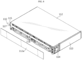
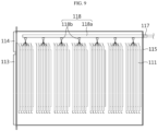
- the fire extinguishing unit 118 may include a pipe shaped unit body 118a and a plurality of spray nozzles 118b as shown in FIGS. 8 and 9 .
- the unit body 118a may be in the shape of a pipe having one end connected to the feed valve 117 and extended along the lengthwise direction of the module housing 112. Additionally, the plurality of spray nozzles 118b may be arranged at a predetermined interval along the lengthwise direction of the unit body 118a and may have outlets facing the cell stack.
- each spray nozzle 118b may include a glass bulb (not shown) configured to close the outlet through which jets of fire fighting water will be emitted in normal situation and open the outlet when thermal damage occurs.
- the glass bulb may be configured to receive a predetermined liquid or gas therein and break by volume expansion of the liquid or gas when it is heated.
- one end of the feed valve 117 may be connected to the connection nozzle 132 of the fire fighting water supply pipe 130, and inside of the rear plate 115, the other end of the feed valve 117, that is, the outlet to which the glass bulb is coupled may be disposed.
- the fire extinguishing unit 118 may be omitted from the inside of the module housing 112.
- the fire fighting water may be only fed into the battery module 110 in which the thermal event occurred among each battery module 110 included in the battery rack 100.
- the drainage mechanism of the fire fighting water after feeding the fire fighting water when a thermal event occurs in the battery module 110 will be described with reference to FIG. 10 below.
- the outlet of the spray nozzle 118b in the second battery module 110 is open. Then, by a pressure difference, the fire fighting water enters the battery module 110 through the feed valve 117 of the second battery module 110 from the supply pipe, moves along the unit body 118a and exits through the outlet of each spray nozzle.
- the fire fighting water when the fire fighting water is directly fed into the second battery module 110 in which the thermal event occurs among the plurality of battery modules 110, it may be possible to suppress the fire situation or thermal runaway situation in the second battery module 110 more rapidly and effectively at the early stage. As a result, it may be possible to prevent thermal runaway or flame propagation to the other battery modules 110, and moreover, to prevent damage to the entire energy storage system 200 including the battery rack 200.
- the module housing 112 of the battery module 110 does not have a completely airtight structure. That is, the module housing 112 may have a gap due to the air conditioning hole 116 or the cooling fan 114 and an assembly clearance. Accordingly, the fire fighting water fed into the battery module 110 may leak out of the battery module 110 due to the above-described factors. When the fire fighting water leaking out of the battery module 110 flows into the other normal battery modules 110, it may cause serious flood damage to the corresponding battery modules 110.
- the battery rack 100 may be configured to receive each battery module 110 in the receiving portions 121 having a structure in which the upper and lower sides and the left and right sides are closed except the front and rear sides, in order to prevent flood damage to the other normal battery module 110.
- the fire fighting water is only drained in the frontward direction and the rearward direction of the rack case 120 as shown in FIG. 10 . Accordingly, the risk of flood damage of the other normal battery modules 110 is very low.
- the flow of the fire fighting water may be guided further outwards along the drain guide unit 140 to cause the fire fighting water to be dropped down to the location spaced the predetermined distance apart from the front outer surface or the rear outer surface of the rack case 120.
- the drain guide units 140 are vertically disposed in multistep arrangement along the heightwise direction of the rack case 120, and the drain guide units 140 disposed at lower positions protect each battery module 110 from the fire fighting water falling down from the height of the second battery module 110, thereby further reducing the flood damage risk of the other normal battery modules 110 below the second battery module 110.
- the rack case 120 of this embodiment has the wall protruding from the bottom surface of each receiving portion 121 at the rear open end of each receiving portion 121, inside the receiving portion 121, the fire fighting water may be blocked by the wall and move to the front side of the receiving portion 121 as indicated by 'F1' in FIG. 10 . Accordingly, most of the fire fighting water may be drained in the frontward direction of the rack case 120.
- the battery rack 100 may prevent the fire fighting water fed into the battery module 110 in which the thermal event occurred from entering the other adjacent battery modules 110.
- the energy storage system 200 may include at least one battery rack 100 described above.
- the energy storage system 200 may include a plurality of battery racks 100, a container 210 accommodating the plurality of battery racks 100 and a connection pipe 220 connected to the fire fighting water supply pipe 130 of each battery rack 100.
- the energy storage system 200 may further include an air conditioning device to manage the temperature in the container 210, a Master Battery Management System to control all the battery racks 100 or the like.
Landscapes
- Chemical & Material Sciences (AREA)
- Chemical Kinetics & Catalysis (AREA)
- Electrochemistry (AREA)
- General Chemical & Material Sciences (AREA)
- Engineering & Computer Science (AREA)
- Manufacturing & Machinery (AREA)
- Health & Medical Sciences (AREA)
- Public Health (AREA)
- Business, Economics & Management (AREA)
- Emergency Management (AREA)
- Battery Mounting, Suspending (AREA)
- Secondary Cells (AREA)
Abstract
Description
- The present disclosure relates to a battery rack and an energy storage system including the same, and more particularly, to a battery rack with a drainage structure for preventing a fire fighting water fed into a battery module in which a thermal event occurred from entering other adjacent battery modules and an energy storage system including the same.
- The present application claims priority to
Korean Patent Application No. 10-2022-0054389 filed on May 2, 2022 - Secondary batteries widely used at present include lithium ion batteries, lithium polymer batteries, nickel cadmium batteries, nickel hydrogen batteries, nickel zinc batteries or the like. Among them, lithium secondary batteries have little or no memory effect, and thus they are gaining more attention than nickel-based secondary batteries for their advantages that recharging can be done whenever it is convenient, the self-discharge rate is very low and the energy density is high.
- In general, lithium secondary batteries may be classified into can type secondary batteries in which an electrode assembly is included in a metal can and pouch type secondary batteries in which an electrode assembly is included in a pouch of an aluminum laminate sheet according to the shape of outer packaging.
- A secondary battery may be used alone, but in general, since the voltage of a secondary battery is about 2.5V to 4.5V, when a higher output voltage is required, a plurality of secondary batteries may be connected in series and/or in parallel to form a battery module. Additionally, a battery module may be used alone, or two or more battery modules may be electrically connected in series and/or in parallel to form a device of higher level such as a battery rack or a battery pack.
- Recently, with the rising issues such as energy shortage or eco-friendly energy, attention is paid to an energy storage system including a plurality of battery racks to store power during off-peak hours and use the stored power during peak hours.
- In an example, an industrial energy storage system includes battery racks, each including a rack case and a plurality of battery modules which is received in the rack case along the vertical direction, and a container accommodating the battery racks, an air conditioning device for managing the temperature of the battery racks and a fire extinguishing device for fire prevention or the like.
- More recently, as the fire safety measures of the energy storage system, a fire extinguishing system is introduced into the energy storage system, the fire extinguishing system designed to, in the event of thermal runaway of battery cells in a specific battery module mounted in a battery rack, feed a fire fighting water into the specific battery module before heat propagation to the other battery modules in order to suppress the fire.
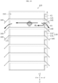
- However, as shown in
FIG. 1 , the conventional battery rack includes the rack case in the shape of a frame with open upper, lower, left and right sides and battery modules stacked in multistep arrangement in the rack case without a proper drainage structure, and thus after the fire fighting water is fed into the battery module by the fire extinguishing system, when leakage of the fire fighting water occurs in the corresponding battery module, the fire fighting water may easily enter the other adjacent battery module. In this case, the other adjacent battery modules may suffer flood damage, causing loss, for example, even normal battery modules may spoil. - The present disclosure is designed to solve the above-described problem, and therefore the present disclosure is directed to providing a battery rack having a drainage structure for preventing a fire fighting water fed into a battery module in which a thermal event occurred from entering other adjacent battery modules and an energy storage system including the same.
- The technical problem to be solved by the present disclosure is not limited to the above-described problems, and these and other problems will be clearly understood by those skilled in the art from the following description.
- To achieve the above-described objective, a battery rack according to the present disclosure may include a plurality of battery modules; a rack case having receiving portions, each configured to insert and receive each of the plurality of battery modules at each predetermined height, and having a structure in which upper and lower sides and left and right sides are closed except front and rear sides; a fire fighting water supply pipe connected to each of the battery modules received in the receiving portions to supply a fire fighting water when a fire occurs; and a drain guide unit disposed on at least one surface of a front outer surface or a rear outer surface of the rack case, and configured to guide drainage of the fire fighting water to cause the fire fighting water coming out of the battery module after having been fed into the battery module to be dropped down to a location spaced a predetermined distance apart from the outer surface of the rack case.
- The drain guide unit may be coupled to the outer surface of the rack case at a location which is lower than an upper battery module of every two battery modules vertically adjacent to each other and higher than a lower battery module.
- The drain guide unit may protrude from the outer surface of the rack case so that a predetermined angle is formed between a plate surface of the drain guide unit and the outer surface of the rack case.
- The drain guide unit ay be rotatably coupled to the outer surface of the rack case.
- The drain guide unit may be configured to cover the receiving portion located on the drain guide unit when it is rotated upwards.
- The drain guide unit may be configured to open the receiving portion located on the drain guide unit when it is rotated downwards.
- The drain guide unit may include a drain guide plate of a plate shape hinged to the outer surface of the rack case; and a stopper configured to limit rotation of the drain guide plate so that the drain guide plate is at a preset angle with respect to the outer surface of the rack case.
- The stopper may be in a shape of a protrusion which protrudes from an edge area of the drain guide plate close to a rotation axis so as to come in contact with the outer surface of the rack case at the preset angle.
- The drain guide unit may further include a magnet at an edge area opposite a rotation axis of the drain guide plate, to allow the drain guide plate rotated upwards to be fixed in parallel to the outer surface of the rack case.
- The drain guide unit may include a first drain guide unit disposed on a front outer surface of the rack case; and a second drain guide unit disposed on a rear outer surface of the rack case.
- In the rack case, the receiving portion may have a narrower horizontal width of a rear open end than a front open side, and the fire fighting water supply pipe may be connected to each battery module through the rear outer surface of the rack case.
- The first drain guide unit may be provided in a size to cover a front open end of each receiving portion, and the second drain guide unit may be provided in a size to cover a rear open end of each receiving portion.
- The battery module may include a fan in a front surface of a module housing and an air conditioning hole in a rear surface of the module housing, and may be inserted into the receiving portion through the rear open end of the receiving portion such that the air conditioning hole is exposed.
- When the battery module is inserted into the receiving portion, a portion of the rear surface of the module housing below the air conditioning hole may be closed by the rear outer surface of the rack case.
- According to another aspect of the present disclosure, there may be provided an energy storage system including at least one battery rack described above.
- According to the present disclosure, it may be possible to prevent the fire fighting water fed into any battery module of the battery rack in which a thermal event occurred from entering the other adjacent battery modules in the event of overflow and leakage of the fire fighting water. Accordingly, when the fire fighting water is fed into the battery rack, the other battery modules except the battery module in which the thermal event occurred may avoid flood damage.
- The effect of the present disclosure is not limited to the above-described effects, and these and other effects will be clearly understood by those skilled in the art from this disclosure and the accompanying drawings.
-
-
FIG. 1 is a diagram schematically showing an area of a battery rack according to a related art. -
FIG. 2 is a perspective view schematically showing a battery rack according to an embodiment of the present disclosure before insertion of a battery module. -
FIG. 3 is a perspective view schematically showing a battery rack according to an embodiment of the present disclosure after insertion of a battery module. -
FIG. 4 is a front view of the battery rack ofFIG. 3 . -
FIG. 5 is a rear view of the battery rack ofFIG. 3 . -
FIG. 6 is a side view of the battery rack ofFIG. 3 . -
FIG. 7 is a diagram showing a rear side of a battery module having an air conditioning hole and a feed valve according to an embodiment of the present disclosure. -
FIG. 8 is a partial cross-sectional view of the battery module ofFIG. 7 . -
FIG. 9 is a schematic cross-sectional view of the battery module ofFIG. 7 . -
FIG. 10 is a diagram illustrating an example of feeding and drainage of a fire fighting water into/from a battery rack according to an embodiment of the present disclosure. -
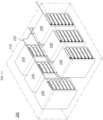
FIG. 11 is a diagram schematically showing an energy storage system according to an embodiment of the present disclosure. - Hereinafter, exemplary embodiments of the present disclosure will be described in detail with reference to the accompanying drawings. Prior to the description, it should be understood that the terms or words used in the specification and the appended claims should not be construed as limited to general and dictionary meanings, but rather interpreted based on the meanings and concepts corresponding to the technical aspect of the present disclosure on the basis of the principle that the inventor is allowed to define terms appropriately for the best explanation. Therefore, the embodiments described herein and illustrations in the accompanying drawings are exemplary embodiments of the present disclosure to describe the technical aspect of the present disclosure and are not intended to be limiting, and thus it should be understood that a variety of other equivalents and modifications could have been made at the time that the application was filed.
-
FIG. 2 is a perspective view schematically showing a battery rack according to an embodiment of the present disclosure before insertion of a battery module,FIG. 3 is a perspective view schematically showing the battery rack according to an embodiment of the present disclosure after insertion of a battery module,FIG. 4 is a front view of the battery rack ofFIG. 3 , andFIG. 5 is a rear view of the battery rack ofFIG. 3 . - Referring to
FIGS. 2 to 5 , thebattery rack 100 according to an embodiment of the present disclosure may include a plurality ofbattery modules 110, arack case 120, a fire fightingwater supply pipe 130 and adrain guide unit 140. - Each
battery module 110 may includesecondary batteries 111 and amodule housing 112 accommodating thesecondary batteries 111 and may be configured to store and release electrical energy. Here, thesecondary batteries 111 may be connected in series and/or in parallel within themodule housing 112 according to the required capacity and output for thebattery module 110. - Additionally, each
battery module 110 may include acooling fan 114 and anair conditioning hole 116 to dissipate heat generated during charging/discharging. For example, thecooling fan 114 may be disposed in the front surface portion of themodule housing 112 and theair conditioning hole 116 may be disposed in the rear surface portion of themodule housing 112. When thecooling fan 114 operates, after the outside air enters thebattery module 110 through theair conditioning hole 116 in the rear surface portion of thebattery module 110 and absorbs heat of thesecondary batteries 111, the air may be forced out through thecooling fan 114 in the front surface portion of thebattery module 110. On the contrary to this embodiment, thecooling fan 114 may be disposed in the rear surface of thebattery module 110 and theair conditioning hole 116 may be disposed in the front surface of thebattery module 110. - Additionally, each
battery module 110 may be configured to directly feed the fire fighting water into themodule housing 112 in case of a situation in which a thermal event such as thermal runaway, fire, explosion or the like occurs in thesecondary battery 111 during charging/discharging. For example, the fire fightingwater supply pipe 130 is connected to the rear surface of eachbattery module 110, and when a thermal event occurs, the fire fighting water may be fed into thecorresponding battery module 110. Its detailed description will be provided below. - As shown in
FIG. 3 , therack case 120 may be approximately cuboidal in shape to insert and receive each of the plurality ofbattery modules 110 at each predetermined height. Additionally, therack case 120 may be made of a stiff material, preferably, a metallic or non-metallic material having high mechanical strength to protect thebattery modules 110 from impacts or vibration. - In particular, the
rack case 120 according to the present disclosure may include a plurality of receivingportions 121 along the vertical direction and may be configured to receive eachbattery module 110 in each receivingportion 121. Each receivingportion 121 may have a structure in which the upper, lower, left and right sides (+Z,-Z,-X,+X) are closed except the front side (-Y) and the rear side (+Y). That is, as opposed to the conventional rack case 1 (seeFIG. 1 ) having a structure in which front, rear, upper, lower, left and right sides are open, therack case 120 according to the present disclosure has a structure in which upper, lower, left and right sides are closed. - In the case of the
rack case 1 having the open upper, lower, left and right sides as shown inFIG. 1 as described in the background part of the specification, when the fire fighting water is fed into thespecific battery module 2, in case where leakage of the fire fighting water occurs in thebattery module 2, thebattery modules 2 located below the correspondingbattery module 2 may suffer flood damage. To solve this problem, therack case 120 according to the present disclosure may be configured such that the upper, lower, left and right sides of each receivingportion 121 are closed and the front and rear sides are open to prevent flood damage of theother battery modules 110 and guide the drainage of the fire fighting water in the frontward or rearward direction when suppressing fire using the fire fighting water. - Additionally, the
drain guide unit 140 may be disposed on at least one side of the front outer surface or the rear outer surface of therack case 120 to cause the fire fighting water to be dropped down to a location spaced a predetermined distance apart from the outer surface of therack case 120 when the fire fighting water coming out of thebattery module 110 moves to the front side or rear side of therack case 120 and falls out of therack case 120. - As shown in
FIG. 3 , thedrain guide unit 140 may protrude from the outer surface of therack case 120 with inclination of a predetermined angle so that the predetermined angle is formed between the plate surface thedrain guide unit 140 and the outer surface of the rack case. For example, thedrain guide unit 140 may protrude outwards with inclination of the predetermined angle on the basis of the outer surface of therack case 120 perpendicular to the ground, and may act as eaves to protect and cover thebattery module 110 in the underlying receivingportion 121 from the fire fighting water falling down from above. Additionally, thedrain guide unit 140 may play a role in preventing venting gas to flames from thebattery module 110 from spreading to thebattery module 110 located on or below in the event of a fire in thebattery module 110. - Specifically, as shown in
FIGS. 3 and4 , thedrain guide unit 140 may be coupled to the outer surface of therack case 120 at a location that is lower than theupper battery module 110 of every twobattery modules 110 vertically adjacent to each other and higher than thelower battery module 110. That is, the plurality ofdrain guide units 140 may be arranged along the vertical direction, and may be coupled to the outer surface of therack case 120 at each height between theupper battery module 110 and thelower battery module 110. For example, in this embodiment, thebattery rack 100 includes sevenbattery modules 110 stacked in the vertical direction, and in this case, sixdrain guide units 140 may be coupled to the frontouter surface 120F of therack case 120, and another sixdrain guide units 140 may be coupled to the rearouter surface 120R of therack case 120. Then, when the fire fighting water is fed in response to a thermal event in any of the sevenbattery modules 110, theother battery modules 110 except thecorresponding battery module 110 may avoid flood damage caused by the fire fighting water. - Referring to
FIG. 3 , seeing the front surface portion of therack case 120, thedrain guide unit 140 is configured to partially cover the front side of a front open end of the underlying receivingportion 121. In this case, when thebattery module 110 while placed in horizontal condition is directly inserted into the receivingportion 121, thebattery module 110 cannot be inserted into the receivingportion 121 due to interference with thedrain guide unit 140. Unlike this embodiment, the eaves of thedrain guide unit 140 may be short in length to avoid interference with thedrain guide unit 140 when inserting thebattery module 110 into the receivingportion 121. However, in this embodiment, the eaves of thedrain guide unit 140 is long in length to drain the fire fighting water by thedrain guide unit 140 more effectively. - In this case, to overcome the difficult when inserting the
battery module 110 into the receivingportion 121, thebattery rack 100 according to this embodiment includes thedrain guide unit 140 of rotatable type. - Additionally, as shown in
FIG. 2 , before inserting thebattery module 110 into the receivingportion 121 of therack case 120, thedrain guide unit 140 may be rotated and attached to the outer surface of therack case 120. - The
drain guide unit 140 is configured to rotate in the upward direction to cover the receivingportion 121 located on the correspondingdrain guide unit 140. On the contrary, thedrain guide unit 140 may be configured to rotate in the downward direction to open the receivingportion 121 located on the correspondingdrain guide unit 140. In this instance, thegrain guide unit 140 rotated in the downward direction may act as eaves for the underlying receivingportion 121 as shown inFIG. 3 . - By the above-described configuration, when receiving the
battery module 110 in therack case 120, for example, as shown inFIG. 2 , thebattery module 110 is inserted into the bottommost receivingportion 121 of therack case 120, and thedrain guide unit 140 located immediately on the bottommost receivingportion 121 is rotated in the downward direction by the predetermined angle. In this instance, thesecond receiving portion 121 of therack case 120 from the bottom is open. Thebattery module 110 is inserted into the open second receivingportion 121. In this pattern, thebattery modules 110 are inserted in a sequential order from the bottommost receivingportion 121 of therack case 120 to the topmost receivingportion 121. Then, thebattery modules 110 are received in therack case 120, and as shown inFIG. 3 , eachdrain guide unit 140 protrudes from the outer surface of therack case 120 at the predetermined angle between thedrain guide unit 140 and the outer surface of therack case 120. - The
drain guide unit 140 may include adrain guide plate 141 and astopper 142. - The
drain guide plate 141 may be in the shape of a plate that is hinged 143 to the outer surface of therack case 120. Thedrain guide plate 141 may be provided in a size to cover the receivingportion 121 located on thedrain guide plate 141 when it is rotated upwards and attached to the outer surface of therack case 120 and may be made of any stiff material, for example, plastics or metals. Additionally, thedrain guide plate 141 may have amagnet 144 in the opposite edge area to the hinged 143 edge area as shown in the enlarged diagram ofFIG. 2 . Themagnet 144 may be used to rotate thedrain guide plate 141 upwards and fix it to the outer surface of therack case 120. - Additionally, as shown in
FIG. 3 , thedrain guide unit 140 has a structure in which thestopper 142 is incorporated into thedrain guide plate 141 so that when thedrain guide plate 141 rotates in the downward direction (-Z direction), the rotation may stop at the predetermined angle. - That is, when the
drain guide plate 141 is at the preset angle θ with respect to the outer surface of therack case 120, one surface of thestopper 142 comes into contact with the outer surface of the rack case, thereby limiting the rotation of thedrain guide plate 141. Here, the preset angle θ may be, for example, determined in a range between 30° and 60°. Accordingly, thedrain guide unit 140 may act as eaves for the underlying receivingportion 121. - In the case of this embodiment, the
stopper 142 may be in the shape of a protrusion that protrudes from the edge area of thedrain guide plate 141 close to the rotation axis so as to contact the outer surface of therack case 120 at the preset angle θ as shown in the enlarged section ofFIG. 3 . - The protrusion may be preferably in the shape of an approximately right-angled triangle in cross section and extended to a length corresponding to the horizontal (±X direction) width of the
drain guide plate 141. By thestopper 142, thedrain guide plate 141 rotates in the downward direction, and stops when the hypotenuse of the right-angled triangle comes into contact with the outer surface of therack case 120. Accordingly, thedrain guide plate 141 may form the eave structure that protrudes with inclination of the preset angle with respect to the outer surface of therack case 120. - Meanwhile, the
drain guide unit 140 according to this embodiment includes a firstdrain guide unit 140A on the frontouter surface 120F of therack case 120 as shown inFIG. 4 , and a seconddrain guide unit 140B on the rearouter surface 120R of therack case 120 as shown inFIG. 5 . - The first
drain guide unit 140A may be provided in a size to cover the front open end of each receivingportion 121, and the seconddrain guide unit 140B may be provided in a size to cover the rear open end of each receivingportion 121. For example, as described above, the firstdrain guide unit 140A may be provided in a size to cover the front open end of the receivingportion 121 when the firstdrain guide unit 140A is rotated in the upward direction (+Z direction) and attached to the front outer surface of therack case 120 as shown inFIG. 2 , and likewise, the seconddrain guide unit 140B may be provided in a size to cover the rear open end of the receivingportion 121 when the seconddrain guide unit 140B is rotated in the upward direction (+Z direction) and attached to the rear outer surface of therack case 120. - That is, as shown in
FIGS. 4 and5 , when the size of the front open end of the receivingportion 121 and the size of the rear open end are different, the size of the firstdrain guide unit 140A and the size of the seconddrain guide unit 140B corresponding to them may be different. - In particular, in this embodiment, each receiving
portion 121 of therack case 120 has the narrower horizontal width (±X direction) of the rear open end than the horizontal width of the front open end. In other words, as shown inFIG. 5 , the horizontal width of the rear open end of the receivingportion 121 has a width as much as 'L1'. This is to place the fire fightingwater supply pipe 130 and the seconddrain guide unit 140B in the rearouter surface 120R of therack case 120 without interference. That is, the fire fightingwater supply pipe 130 may be disposed in the remaining portion as much as 'L2' inFIG. 5 to avoid interference with the seconddrain guide unit 140B. - The fire fighting
water supply pipe 130 is configured to supply the fire fighting water to eachbattery module 110 in case of emergency, and may be configured to pass through the rear outer surface of therack case 120 and connect to thebattery module 110 disposed in the receivingportion 121. For example, as shown inFIG. 6 , the fire fightingwater supply pipe 130 may include amain pipe 131 disposed in the vertical direction with respect to therack case 120 and a plurality ofconnection nozzles 132 branching off from themain pipe 131 perpendicularly to themain pipe 131, and eachconnection nozzle 132 may be connected to afeed valve 117 disposed in the rear surface of thebattery module 110 through the rear outer surface of therack case 120. For reference, eachconnection nozzle 132 may be inserted into therack case 120 through a through-hole (not shown) formed in the rear outer surface of therack case 120. - Subsequently, the configuration of the
battery module 110 for feeding the fire fighting water into thebattery module 110 in the event of thermal runaway or fire in thesecondary batteries 111 will be described with reference toFIGS. 7 to 9 . - As described above, the
battery module 110 may include themodule housing 112, thesecondary batteries 111 received in themodule housing 112, theair conditioning hole 116 and thefeed valve 117 in the rear surface of themodule housing 112 and the coolingfan 114 in the front surface of themodule housing 112. - Accordingly, when the
battery module 110 is inserted into the receivingportion 121 of therack case 120, the coolingfan 114 may be disposed on the front side of therack case 120 and theair conditioning hole 116 and thefeed valve 117 may be disposed on the rear side of therack case 120. When thebattery module 110 is inserted and disposed in the receivingportion 121 of therack case 120, the lower part of theair conditioning hole 116 may be closed by the rear outer surface of therack case 120. That is, as indicated by 'K1' inFIGS. 5 and6 , therack case 120 may have a wall that protrudes from the bottom surface of each receivingportion 121 at the rear open end of each receivingportion 121. The wall plays a role in preventing the fire fighting water from leaking through the rear side of the receivingportion 121. - The
module housing 112 may be in the shape of an approximately cuboidal box having an internal space for receiving a cell stack formed by stacking thesecondary batteries 111 in one direction, and including a bottom plate, a top plate, left andright side plates 112a, afront plate 113 and arear plate 115. Here, the six plates may be assemblable and disassemblable, but may be partially assemblable and disassemblable by integrally fabricating some of the six plates and individually fabricating the remaining plates. - For the
secondary battery 111, a pouch typesecondary battery 111 may be used. The plurality of pouch typesecondary batteries 111 is stacked in one direction to form the cell stack, and the cell stack is received in themodule housing 112. - The cell stack may be disposed in the
module housing 112 such that the lengthwise direction of the pouch typesecondary batteries 111 is perpendicular to theside plates 112a of themodule housing 112. In other words, as shown inFIG. 9 , when each direction perpendicular to the stack direction of thesecondary batteries 111 is defined as a front surface direction and a rear surface direction of the cell stack, the cell stack may have the front surface portion and the rear surface portion facing the left andright side plates 112a at a predetermined gap between them respectively. As described above, when the cell stack is disposed in themodule housing 112, themodule housing 112 may have an air flow space and a space for placing afire extinguishing unit 118. - The
fire extinguishing unit 118 may include a pipe shapedunit body 118a and a plurality ofspray nozzles 118b as shown inFIGS. 8 and9 . - The
unit body 118a may be in the shape of a pipe having one end connected to thefeed valve 117 and extended along the lengthwise direction of themodule housing 112. Additionally, the plurality ofspray nozzles 118b may be arranged at a predetermined interval along the lengthwise direction of theunit body 118a and may have outlets facing the cell stack. - Although not shown in detail, each
spray nozzle 118b may include a glass bulb (not shown) configured to close the outlet through which jets of fire fighting water will be emitted in normal situation and open the outlet when thermal damage occurs. The glass bulb may be configured to receive a predetermined liquid or gas therein and break by volume expansion of the liquid or gas when it is heated. By the above-described configuration, for example, in a situation in which the temperature in thebattery module 110 rises to 70°C to 100°C above or flames or high temperature venting gas causes thermal damage to the glass bulb, the material in the glass bulb may expand, the glass bulb may rupture and the outlet of thespray nozzle 118b may be open. Then, the jet of fire fighting water in theunit body 118a may be emitted toward the cell stack through the outlet of thespray nozzle 118b. - Unlike this embodiment, outside of the
rear plate 115, one end of thefeed valve 117 may be connected to theconnection nozzle 132 of the fire fightingwater supply pipe 130, and inside of therear plate 115, the other end of thefeed valve 117, that is, the outlet to which the glass bulb is coupled may be disposed. In this case, thefire extinguishing unit 118 may be omitted from the inside of themodule housing 112. - By the above-described method of feeding the fire fighting water, the fire fighting water may be only fed into the
battery module 110 in which the thermal event occurred among eachbattery module 110 included in thebattery rack 100. - With the
battery rack 100 according to an embodiment of the present disclosure, the drainage mechanism of the fire fighting water after feeding the fire fighting water when a thermal event occurs in thebattery module 110 will be described with reference toFIG. 10 below. - For example, when a thermal event occurs in the
second battery module 110 from the top among thebattery modules 110 included in thebattery rack 100 shown inFIG. 10 , the outlet of thespray nozzle 118b in thesecond battery module 110 is open. Then, by a pressure difference, the fire fighting water enters thebattery module 110 through thefeed valve 117 of thesecond battery module 110 from the supply pipe, moves along theunit body 118a and exits through the outlet of each spray nozzle. - As described above, when the fire fighting water is directly fed into the
second battery module 110 in which the thermal event occurs among the plurality ofbattery modules 110, it may be possible to suppress the fire situation or thermal runaway situation in thesecond battery module 110 more rapidly and effectively at the early stage. As a result, it may be possible to prevent thermal runaway or flame propagation to theother battery modules 110, and moreover, to prevent damage to the entireenergy storage system 200 including thebattery rack 200. - Meanwhile, the
module housing 112 of thebattery module 110 does not have a completely airtight structure. That is, themodule housing 112 may have a gap due to theair conditioning hole 116 or the coolingfan 114 and an assembly clearance. Accordingly, the fire fighting water fed into thebattery module 110 may leak out of thebattery module 110 due to the above-described factors. When the fire fighting water leaking out of thebattery module 110 flows into the othernormal battery modules 110, it may cause serious flood damage to thecorresponding battery modules 110. - As described above, the
battery rack 100 according to the present disclosure may be configured to receive eachbattery module 110 in the receivingportions 121 having a structure in which the upper and lower sides and the left and right sides are closed except the front and rear sides, in order to prevent flood damage to the othernormal battery module 110. For example, when leakage of the fire fighting water occur in thesecond battery module 110, the fire fighting water is only drained in the frontward direction and the rearward direction of therack case 120 as shown inFIG. 10 . Accordingly, the risk of flood damage of the othernormal battery modules 110 is very low. - Moreover, when the fire fighting water is drained out of the receiving
portion 121 in which thesecond battery module 110 is present, the flow of the fire fighting water may be guided further outwards along thedrain guide unit 140 to cause the fire fighting water to be dropped down to the location spaced the predetermined distance apart from the front outer surface or the rear outer surface of therack case 120. Additionally, thedrain guide units 140 are vertically disposed in multistep arrangement along the heightwise direction of therack case 120, and thedrain guide units 140 disposed at lower positions protect eachbattery module 110 from the fire fighting water falling down from the height of thesecond battery module 110, thereby further reducing the flood damage risk of the othernormal battery modules 110 below thesecond battery module 110. - Additionally, since the
rack case 120 of this embodiment has the wall protruding from the bottom surface of each receivingportion 121 at the rear open end of each receivingportion 121, inside the receivingportion 121, the fire fighting water may be blocked by the wall and move to the front side of the receivingportion 121 as indicated by 'F1' inFIG. 10 . Accordingly, most of the fire fighting water may be drained in the frontward direction of therack case 120. - As described above, the
battery rack 100 according to the present disclosure may prevent the fire fighting water fed into thebattery module 110 in which the thermal event occurred from entering the otheradjacent battery modules 110. - Meanwhile, the
energy storage system 200 according to the present disclosure may include at least onebattery rack 100 described above. - For example, as shown in
FIG. 11 , theenergy storage system 200 may include a plurality ofbattery racks 100, acontainer 210 accommodating the plurality ofbattery racks 100 and aconnection pipe 220 connected to the fire fightingwater supply pipe 130 of eachbattery rack 100. - Although not shown in the drawing for convenience of description, the
energy storage system 200 may further include an air conditioning device to manage the temperature in thecontainer 210, a Master Battery Management System to control all the battery racks 100 or the like. - While the present disclosure has been hereinabove described with regard to a limited number of embodiments and drawings, the present disclosure is not limited thereto and it is apparent that a variety of changes and modifications may be made by those skilled in the art within the technical aspect of the present disclosure and the scope of the appended claims and their equivalents.
- The terms indicating directions such as upper, lower, left, right, front and rear are used for convenience of description, but it is obvious to those skilled in the art that the terms may change depending on the position of the stated element or an observer.
Claims (15)
- A battery rack, comprising:a plurality of battery modules;a rack case having receiving portions, each configured to insert and receive each of the plurality of battery modules at each predetermined height, and having a structure in which upper and lower sides and left and right sides are closed except front and rear sides;a fire fighting water supply pipe connected to each of the battery modules received in the receiving portions to supply a fire fighting water when a fire occurs; anda drain guide unit disposed on at least one surface of a front outer surface or a rear outer surface of the rack case, and configured to guide drainage of the fire fighting water to cause the fire fighting water coming out of the battery module after having been fed into the battery module to be dropped down to a location spaced a predetermined distance apart from the outer surface of the rack case.
- The battery rack according to claim 1, wherein the drain guide unit is coupled to the outer surface of the rack case at a location which is lower than an upper battery module of every two battery modules vertically adjacent to each other and higher than a lower battery module.
- The battery rack according to claim 1, wherein the drain guide unit protrudes from the outer surface of the rack case so that a predetermined angle is formed between a plate surface of the drain guide unit and the outer surface of the rack case.
- The battery rack according to claim 3, wherein the drain guide unit is rotatably coupled to the outer surface of the rack case.
- The battery rack according to claim 4, wherein the drain guide unit is configured to cover the receiving portion located on the drain guide unit when it is rotated upwards.
- The battery rack according to claim 4, wherein the drain guide unit is configured to open the receiving portion located on the drain guide unit when it is rotated downwards.
- The battery rack according to claim 4, wherein the drain guide unit includes:a drain guide plate of a plate shape hinged to the outer surface of the rack case; anda stopper configured to limit rotation of the drain guide plate so that the drain guide plate is at a preset angle with respect to the outer surface of the rack case.
- The battery rack according to claim 7, wherein the stopper is in a shape of a protrusion which protrudes from an edge area of the drain guide plate close to a rotation axis so as to come in contact with the outer surface of the rack case at the preset angle.
- The battery rack according to claim 7, wherein the drain guide unit further includes a magnet at an edge area opposite a rotation axis of the drain guide plate, to allow the drain guide plate rotated upwards to be fixed in parallel to the outer surface of the rack case.
- The battery rack according to claim 1, wherein the drain guide unit includes:a first drain guide unit disposed on a front outer surface of the rack case; anda second drain guide unit disposed on a rear outer surface of the rack case.
- The battery rack according to claim 10, wherein in the rack case, the receiving portion has a narrower horizontal width of a rear open end than a front open side, and
wherein the fire fighting water supply pipe is connected to each battery module through the rear outer surface of the rack case. - The battery rack according to claim 10, wherein the first drain guide unit is provided in a size to cover a front open end of each receiving portion, and
wherein the second drain guide unit is provided in a size to cover a rear open end of each receiving portion. - The battery rack according to claim 11, wherein the battery module includes a fan in a front surface of a module housing and an air conditioning hole in a rear surface of the module housing, and is inserted into the receiving portion through the rear open end of the receiving portion such that the air conditioning hole is exposed.
- The battery rack according to claim 13, wherein when the battery module is inserted into the receiving portion, a portion of the rear surface of the module housing below the air conditioning hole is closed by the rear outer surface of the rack case.
- An energy storage system comprising the battery rack according to any one of claims 1 to 14.
Applications Claiming Priority (2)
| Application Number | Priority Date | Filing Date | Title |
|---|---|---|---|
| KR1020220054389A KR102936348B1 (en) | 2022-05-02 | 2022-05-02 | Battery rack having a drainage structure and energy storage system including the same |
| PCT/KR2023/005827 WO2023214745A1 (en) | 2022-05-02 | 2023-04-27 | Battery rack having a drainage structure and energy storage system including the same |
Publications (2)
| Publication Number | Publication Date |
|---|---|
| EP4456296A1 true EP4456296A1 (en) | 2024-10-30 |
| EP4456296A4 EP4456296A4 (en) | 2025-04-30 |
Family
ID=88646651
Family Applications (1)
| Application Number | Title | Priority Date | Filing Date |
|---|---|---|---|
| EP23799628.5A Pending EP4456296A4 (en) | 2022-05-02 | 2023-04-27 | BATTERY FRAME HAVING DRAINAGE STRUCTURE AND ENERGY STORAGE SYSTEM COMPRISING SAME |
Country Status (7)
| Country | Link |
|---|---|
| US (1) | US20250023216A1 (en) |
| EP (1) | EP4456296A4 (en) |
| JP (1) | JP7834871B2 (en) |
| KR (1) | KR102936348B1 (en) |
| CN (1) | CN118435439A (en) |
| AU (1) | AU2023264413A1 (en) |
| WO (1) | WO2023214745A1 (en) |
Cited By (1)
| Publication number | Priority date | Publication date | Assignee | Title |
|---|---|---|---|---|
| TWI903860B (en) * | 2024-11-12 | 2025-11-01 | 太康精密股份有限公司 | The drainage system of the energy storage equipment and the energy storage equipment itself. |
Families Citing this family (1)
| Publication number | Priority date | Publication date | Assignee | Title |
|---|---|---|---|---|
| CN120341488B (en) * | 2025-04-18 | 2025-11-18 | 东昇照明科技有限公司 | A lithium battery component and a lithium battery packaging housing |
Family Cites Families (7)
| Publication number | Priority date | Publication date | Assignee | Title |
|---|---|---|---|---|
| JP2013065419A (en) * | 2011-09-16 | 2013-04-11 | Mitsubishi Motors Corp | Battery pack |
| CN104001297B (en) | 2014-05-21 | 2016-08-24 | 中国南方电网有限责任公司调峰调频发电公司 | A kind of lithium ion battery fire-fighting experiment cabinet carrying automatic alarm and fire extinguishing system |
| KR200482382Y1 (en) * | 2015-11-03 | 2017-01-17 | 한국단자공업 주식회사 | Water blocking structure for electrical connecting apparatus |
| KR102748983B1 (en) * | 2019-07-03 | 2024-12-30 | 주식회사 엘지에너지솔루션 | Battery Module Including Flame Retardant Plate, Battery Rack and Power Storage Device Including the Same |
| US11061820B2 (en) | 2019-08-30 | 2021-07-13 | Microsoft Technology Licensing, Llc | Optimizing access to page table entries in processor-based devices |
| KR102668862B1 (en) * | 2020-03-04 | 2024-05-22 | 주식회사 엘지에너지솔루션 | Battery Rack And Power Storage System Comprising the Same |
| KR102650084B1 (en) * | 2020-03-04 | 2024-03-20 | 주식회사 엘지에너지솔루션 | Battery rack and energy storage system comprising the battery rack |
-
2022
- 2022-05-02 KR KR1020220054389A patent/KR102936348B1/en active Active
-
2023
- 2023-04-27 WO PCT/KR2023/005827 patent/WO2023214745A1/en not_active Ceased
- 2023-04-27 US US18/713,013 patent/US20250023216A1/en active Pending
- 2023-04-27 AU AU2023264413A patent/AU2023264413A1/en active Pending
- 2023-04-27 CN CN202380015446.9A patent/CN118435439A/en active Pending
- 2023-04-27 JP JP2024540984A patent/JP7834871B2/en active Active
- 2023-04-27 EP EP23799628.5A patent/EP4456296A4/en active Pending
Cited By (1)
| Publication number | Priority date | Publication date | Assignee | Title |
|---|---|---|---|---|
| TWI903860B (en) * | 2024-11-12 | 2025-11-01 | 太康精密股份有限公司 | The drainage system of the energy storage equipment and the energy storage equipment itself. |
Also Published As
| Publication number | Publication date |
|---|---|
| KR102936348B1 (en) | 2026-03-06 |
| CN118435439A (en) | 2024-08-02 |
| JP2025503624A (en) | 2025-02-04 |
| KR20230154678A (en) | 2023-11-09 |
| WO2023214745A1 (en) | 2023-11-09 |
| JP7834871B2 (en) | 2026-03-24 |
| US20250023216A1 (en) | 2025-01-16 |
| AU2023264413A1 (en) | 2024-08-15 |
| EP4456296A4 (en) | 2025-04-30 |
Similar Documents
| Publication | Publication Date | Title |
|---|---|---|
| EP4024590B1 (en) | Battery module having structure capable of delaying outflow of fire-fighting water injected therein in case of fire, and battery rack and energy storage device comprising same | |
| CN114303280B (en) | Battery rack and energy storage system including the battery rack | |
| US20250023216A1 (en) | Battery rack having drainage structure and energy storage system including the same | |
| EP4459737A1 (en) | Energy storage system | |
| US12463273B2 (en) | Battery module, battery rack comprising same, and power storage device | |
| US10193200B2 (en) | Battery module and battery pack comprising same | |
| KR20230001546A (en) | Battery pack and energy storage system including same | |
| EP4044324B1 (en) | Battery module having structure capable of rapid cooling, and ess comprising same | |
| EP4468490A1 (en) | Battery pack and vehicle including same | |
| KR20230154680A (en) | Energy storage system capable of recovering and circulating fire waters | |
| JP7417764B2 (en) | Battery racks, power storage devices, and power generation systems | |
| KR20230039836A (en) | Battery module with heat transfer blocking structure in case of internal fire | |
| KR20230105641A (en) | Battery pack with fire water storage tank and wall mount unit | |
| EP4290679A1 (en) | Battery pack with improved safety | |
| CN119495894A (en) | A battery module capable of effectively preventing thermal runaway from spreading, a protection method thereof, and an energy storage device | |
| KR20230100621A (en) | Battery pack with fire fighting water storage tank | |
| EP4027434A1 (en) | Battery module having structure enabling rapid deployment of sprinkler, and ess including same | |
| KR20230154679A (en) | Energy storage system capable of recovering fire water supplied to a battery rack | |
| CN223462372U (en) | Battery module capable of effectively preventing thermal runaway diffusion and energy storage device comprising battery module | |
| KR20250036622A (en) | Battery pack and ess comprising the battery pack | |
| EP4024566A1 (en) | Battery module having structure capable of rapid cooling, and ess comprising same | |
| KR20230095799A (en) | Battery pack with improved safety |
Legal Events
| Date | Code | Title | Description |
|---|---|---|---|
| STAA | Information on the status of an ep patent application or granted ep patent |
Free format text: STATUS: THE INTERNATIONAL PUBLICATION HAS BEEN MADE |
|
| PUAI | Public reference made under article 153(3) epc to a published international application that has entered the european phase |
Free format text: ORIGINAL CODE: 0009012 |
|
| STAA | Information on the status of an ep patent application or granted ep patent |
Free format text: STATUS: REQUEST FOR EXAMINATION WAS MADE |
|
| 17P | Request for examination filed |
Effective date: 20240725 |
|
| AK | Designated contracting states |
Kind code of ref document: A1 Designated state(s): AL AT BE BG CH CY CZ DE DK EE ES FI FR GB GR HR HU IE IS IT LI LT LU LV MC ME MK MT NL NO PL PT RO RS SE SI SK SM TR |
|
| REG | Reference to a national code |
Ref country code: DE Ref legal event code: R079 Free format text: PREVIOUS MAIN CLASS: H01M0050251000 Ipc: A62C0003160000 |
|
| A4 | Supplementary search report drawn up and despatched |
Effective date: 20250331 |
|
| RIC1 | Information provided on ipc code assigned before grant |
Ipc: H01M 50/691 20210101ALN20250326BHEP Ipc: H01M 10/32 20060101ALI20250326BHEP Ipc: H01M 10/613 20140101ALI20250326BHEP Ipc: H01M 50/204 20210101ALI20250326BHEP Ipc: A62C 3/16 20060101AFI20250326BHEP |
|
| DAV | Request for validation of the european patent (deleted) | ||
| DAX | Request for extension of the european patent (deleted) | ||
| STAA | Information on the status of an ep patent application or granted ep patent |
Free format text: STATUS: EXAMINATION IS IN PROGRESS |
|
| 17Q | First examination report despatched |
Effective date: 20250923 |
|
| GRAP | Despatch of communication of intention to grant a patent |
Free format text: ORIGINAL CODE: EPIDOSNIGR1 |
|
| STAA | Information on the status of an ep patent application or granted ep patent |
Free format text: STATUS: GRANT OF PATENT IS INTENDED |
|
| RIC1 | Information provided on ipc code assigned before grant |
Ipc: A62C 3/16 20060101AFI20260326BHEP Ipc: H01M 50/204 20210101ALI20260326BHEP Ipc: H01M 10/613 20140101ALI20260326BHEP Ipc: H01M 10/32 20060101ALI20260326BHEP Ipc: H01M 50/691 20210101ALN20260326BHEP |