EP4456282A1 - Gasket, secondary battery cap assembly comprising same, and secondary battery comprising same - Google Patents
Gasket, secondary battery cap assembly comprising same, and secondary battery comprising same Download PDFInfo
- Publication number
- EP4456282A1 EP4456282A1 EP22912006.8A EP22912006A EP4456282A1 EP 4456282 A1 EP4456282 A1 EP 4456282A1 EP 22912006 A EP22912006 A EP 22912006A EP 4456282 A1 EP4456282 A1 EP 4456282A1
- Authority
- EP
- European Patent Office
- Prior art keywords
- gasket
- polybutylene terephthalate
- terephthalate resin
- secondary battery
- parts
- Prior art date
- Legal status (The legal status is an assumption and is not a legal conclusion. Google has not performed a legal analysis and makes no representation as to the accuracy of the status listed.)
- Pending
Links
Images
Classifications
-
- H—ELECTRICITY
- H01—ELECTRIC ELEMENTS
- H01M—PROCESSES OR MEANS, e.g. BATTERIES, FOR THE DIRECT CONVERSION OF CHEMICAL ENERGY INTO ELECTRICAL ENERGY
- H01M50/00—Constructional details or processes of manufacture of the non-active parts of electrochemical cells other than fuel cells, e.g. hybrid cells
- H01M50/10—Primary casings; Jackets or wrappings
- H01M50/183—Sealing members
- H01M50/19—Sealing members characterised by the material
- H01M50/195—Composite material consisting of a mixture of organic and inorganic materials
-
- H—ELECTRICITY
- H01—ELECTRIC ELEMENTS
- H01M—PROCESSES OR MEANS, e.g. BATTERIES, FOR THE DIRECT CONVERSION OF CHEMICAL ENERGY INTO ELECTRICAL ENERGY
- H01M50/00—Constructional details or processes of manufacture of the non-active parts of electrochemical cells other than fuel cells, e.g. hybrid cells
- H01M50/10—Primary casings; Jackets or wrappings
- H01M50/183—Sealing members
- H01M50/19—Sealing members characterised by the material
- H01M50/198—Sealing members characterised by the material characterised by physical properties, e.g. adhesiveness or hardness
-
- C—CHEMISTRY; METALLURGY
- C09—DYES; PAINTS; POLISHES; NATURAL RESINS; ADHESIVES; COMPOSITIONS NOT OTHERWISE PROVIDED FOR; APPLICATIONS OF MATERIALS NOT OTHERWISE PROVIDED FOR
- C09K—MATERIALS FOR MISCELLANEOUS APPLICATIONS, NOT PROVIDED FOR ELSEWHERE
- C09K3/00—Materials not provided for elsewhere
- C09K3/10—Materials in mouldable or extrudable form for sealing or packing joints or covers
- C09K3/1006—Materials in mouldable or extrudable form for sealing or packing joints or covers characterised by the chemical nature of one of its constituents
-
- H—ELECTRICITY
- H01—ELECTRIC ELEMENTS
- H01M—PROCESSES OR MEANS, e.g. BATTERIES, FOR THE DIRECT CONVERSION OF CHEMICAL ENERGY INTO ELECTRICAL ENERGY
- H01M10/00—Secondary cells; Manufacture thereof
- H01M10/04—Construction or manufacture in general
-
- H—ELECTRICITY
- H01—ELECTRIC ELEMENTS
- H01M—PROCESSES OR MEANS, e.g. BATTERIES, FOR THE DIRECT CONVERSION OF CHEMICAL ENERGY INTO ELECTRICAL ENERGY
- H01M10/00—Secondary cells; Manufacture thereof
- H01M10/04—Construction or manufacture in general
- H01M10/0422—Cells or battery with cylindrical casing
-
- H—ELECTRICITY
- H01—ELECTRIC ELEMENTS
- H01M—PROCESSES OR MEANS, e.g. BATTERIES, FOR THE DIRECT CONVERSION OF CHEMICAL ENERGY INTO ELECTRICAL ENERGY
- H01M10/00—Secondary cells; Manufacture thereof
- H01M10/05—Accumulators with non-aqueous electrolyte
- H01M10/058—Construction or manufacture
- H01M10/0587—Construction or manufacture of accumulators having only wound construction elements, i.e. wound positive electrodes, wound negative electrodes and wound separators
-
- H—ELECTRICITY
- H01—ELECTRIC ELEMENTS
- H01M—PROCESSES OR MEANS, e.g. BATTERIES, FOR THE DIRECT CONVERSION OF CHEMICAL ENERGY INTO ELECTRICAL ENERGY
- H01M50/00—Constructional details or processes of manufacture of the non-active parts of electrochemical cells other than fuel cells, e.g. hybrid cells
- H01M50/10—Primary casings; Jackets or wrappings
- H01M50/147—Lids or covers
-
- H—ELECTRICITY
- H01—ELECTRIC ELEMENTS
- H01M—PROCESSES OR MEANS, e.g. BATTERIES, FOR THE DIRECT CONVERSION OF CHEMICAL ENERGY INTO ELECTRICAL ENERGY
- H01M50/00—Constructional details or processes of manufacture of the non-active parts of electrochemical cells other than fuel cells, e.g. hybrid cells
- H01M50/10—Primary casings; Jackets or wrappings
- H01M50/147—Lids or covers
- H01M50/148—Lids or covers characterised by their shape
- H01M50/152—Lids or covers characterised by their shape for cells having curved cross-section, e.g. round or elliptic
-
- H—ELECTRICITY
- H01—ELECTRIC ELEMENTS
- H01M—PROCESSES OR MEANS, e.g. BATTERIES, FOR THE DIRECT CONVERSION OF CHEMICAL ENERGY INTO ELECTRICAL ENERGY
- H01M50/00—Constructional details or processes of manufacture of the non-active parts of electrochemical cells other than fuel cells, e.g. hybrid cells
- H01M50/10—Primary casings; Jackets or wrappings
- H01M50/147—Lids or covers
- H01M50/166—Lids or covers characterised by the methods of assembling casings with lids
- H01M50/167—Lids or covers characterised by the methods of assembling casings with lids by crimping
-
- H—ELECTRICITY
- H01—ELECTRIC ELEMENTS
- H01M—PROCESSES OR MEANS, e.g. BATTERIES, FOR THE DIRECT CONVERSION OF CHEMICAL ENERGY INTO ELECTRICAL ENERGY
- H01M50/00—Constructional details or processes of manufacture of the non-active parts of electrochemical cells other than fuel cells, e.g. hybrid cells
- H01M50/10—Primary casings; Jackets or wrappings
- H01M50/147—Lids or covers
- H01M50/166—Lids or covers characterised by the methods of assembling casings with lids
- H01M50/171—Lids or covers characterised by the methods of assembling casings with lids using adhesives or sealing agents
-
- H—ELECTRICITY
- H01—ELECTRIC ELEMENTS
- H01M—PROCESSES OR MEANS, e.g. BATTERIES, FOR THE DIRECT CONVERSION OF CHEMICAL ENERGY INTO ELECTRICAL ENERGY
- H01M50/00—Constructional details or processes of manufacture of the non-active parts of electrochemical cells other than fuel cells, e.g. hybrid cells
- H01M50/10—Primary casings; Jackets or wrappings
- H01M50/183—Sealing members
- H01M50/184—Sealing members characterised by their shape or structure
-
- H—ELECTRICITY
- H01—ELECTRIC ELEMENTS
- H01M—PROCESSES OR MEANS, e.g. BATTERIES, FOR THE DIRECT CONVERSION OF CHEMICAL ENERGY INTO ELECTRICAL ENERGY
- H01M50/00—Constructional details or processes of manufacture of the non-active parts of electrochemical cells other than fuel cells, e.g. hybrid cells
- H01M50/10—Primary casings; Jackets or wrappings
- H01M50/183—Sealing members
- H01M50/186—Sealing members characterised by the disposition of the sealing members
-
- H—ELECTRICITY
- H01—ELECTRIC ELEMENTS
- H01M—PROCESSES OR MEANS, e.g. BATTERIES, FOR THE DIRECT CONVERSION OF CHEMICAL ENERGY INTO ELECTRICAL ENERGY
- H01M50/00—Constructional details or processes of manufacture of the non-active parts of electrochemical cells other than fuel cells, e.g. hybrid cells
- H01M50/10—Primary casings; Jackets or wrappings
- H01M50/183—Sealing members
- H01M50/186—Sealing members characterised by the disposition of the sealing members
- H01M50/188—Sealing members characterised by the disposition of the sealing members the sealing members being arranged between the lid and terminal
-
- H—ELECTRICITY
- H01—ELECTRIC ELEMENTS
- H01M—PROCESSES OR MEANS, e.g. BATTERIES, FOR THE DIRECT CONVERSION OF CHEMICAL ENERGY INTO ELECTRICAL ENERGY
- H01M50/00—Constructional details or processes of manufacture of the non-active parts of electrochemical cells other than fuel cells, e.g. hybrid cells
- H01M50/10—Primary casings; Jackets or wrappings
- H01M50/183—Sealing members
- H01M50/19—Sealing members characterised by the material
- H01M50/193—Organic material
-
- H—ELECTRICITY
- H01—ELECTRIC ELEMENTS
- H01M—PROCESSES OR MEANS, e.g. BATTERIES, FOR THE DIRECT CONVERSION OF CHEMICAL ENERGY INTO ELECTRICAL ENERGY
- H01M50/00—Constructional details or processes of manufacture of the non-active parts of electrochemical cells other than fuel cells, e.g. hybrid cells
- H01M50/30—Arrangements for facilitating escape of gases
- H01M50/342—Non-re-sealable arrangements
- H01M50/3425—Non-re-sealable arrangements in the form of rupturable membranes or weakened parts, e.g. pierced with the aid of a sharp member
-
- C—CHEMISTRY; METALLURGY
- C09—DYES; PAINTS; POLISHES; NATURAL RESINS; ADHESIVES; COMPOSITIONS NOT OTHERWISE PROVIDED FOR; APPLICATIONS OF MATERIALS NOT OTHERWISE PROVIDED FOR
- C09K—MATERIALS FOR MISCELLANEOUS APPLICATIONS, NOT PROVIDED FOR ELSEWHERE
- C09K2200/00—Chemical nature of materials in mouldable or extrudable form for sealing or packing joints or covers
- C09K2200/06—Macromolecular organic compounds, e.g. prepolymers
- C09K2200/0645—Macromolecular organic compounds, e.g. prepolymers obtained otherwise than by reactions involving carbon-to-carbon unsaturated bonds
- C09K2200/0655—Polyesters
-
- H—ELECTRICITY
- H01—ELECTRIC ELEMENTS
- H01M—PROCESSES OR MEANS, e.g. BATTERIES, FOR THE DIRECT CONVERSION OF CHEMICAL ENERGY INTO ELECTRICAL ENERGY
- H01M2200/00—Safety devices for primary or secondary batteries
- H01M2200/20—Pressure-sensitive devices
-
- Y—GENERAL TAGGING OF NEW TECHNOLOGICAL DEVELOPMENTS; GENERAL TAGGING OF CROSS-SECTIONAL TECHNOLOGIES SPANNING OVER SEVERAL SECTIONS OF THE IPC; TECHNICAL SUBJECTS COVERED BY FORMER USPC CROSS-REFERENCE ART COLLECTIONS [XRACs] AND DIGESTS
- Y02—TECHNOLOGIES OR APPLICATIONS FOR MITIGATION OR ADAPTATION AGAINST CLIMATE CHANGE
- Y02E—REDUCTION OF GREENHOUSE GAS [GHG] EMISSIONS, RELATED TO ENERGY GENERATION, TRANSMISSION OR DISTRIBUTION
- Y02E60/00—Enabling technologies; Technologies with a potential or indirect contribution to GHG emissions mitigation
- Y02E60/10—Energy storage using batteries
Definitions
- the present invention relates to a gasket, a cap assembly for a secondary battery including the gasket, and a secondary battery including the cap assembly.
- a secondary battery is classified into a cylindrical secondary battery or prismatic secondary battery in which an electrode assembly is embedded in a cylindrical or prismatic metal can, and a pouch-type secondary battery in which an electrode assembly is embedded in a pouch-type case made of an aluminum laminate sheet.
- the cylindrical secondary battery has the advantage of relatively large capacity and structural stability.
- the cylindrical secondary battery seals off the outside and inside of the cylindrical secondary battery by placing and sealing a cap assembly on top of the open cylindrical case.
- a gasket constituting the cap assembly also has a function of ensuring insulation between a top cap connected to a positive electrode tab of the electrode assembly and a cylindrical case connected to a negative electrode tab.
- the cap assembly for a cylindrical secondary battery is configured by a top cap, a safety vent, a crimping gasket, a current interrupt member, and a lower gasket. Due to deformation of the cap assembly during an external impact, the safety vent is also deformed, which causes the secondary battery to easily short-circuit. In addition, there is a problem that the gasket melts in a high-temperature environment, and thus, an electrode terminal short-circuits.
- the present invention relates to a gasket having excellent heat resistance and strength, a cap assembly for a secondary battery including the gasket, and a secondary battery including the cap assembly.
- An exemplary embodiment of the present invention provides a gasket including a polybutylene terephthalate resin, wherein the polybutylene terephthalate resin has a melt flow rate of 35 g/10min to 60 g/10min.
- An exemplary embodiment of the present invention provides a cap assembly for a secondary battery adapted to be coupled to an opening portion of a can configured to accommodate an electrode assembly, the cap assembly including: a top cap positioned in the opening portion; a safety vent arranged below the top cap and surrounding an outer periphery of the top cap; and the gasket positioned on an outer periphery of the safety vent.
- An exemplary embodiment of the present invention provides a secondary battery including an electrode assembly in such a form that a separator is arranged between a positive electrode and a negative electrode and the positive and negative electrodes and the separator are wound; a can configured to accommodate the electrode assembly; and the cap assembly coupled to an opening portion of the can.
- the gasket material according to an exemplary embodiment of the present invention includes a polybutylene terephthalate resin with a melt flow rate of 35 g/10 min to 60 g/10 min, whereby excellent molding processability, tensile strength, IZOD impact strength, and/or heat distortion temperature can be exhibited.
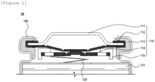
- FIG. 1 is a vertical cross-sectional view of an opening portion of a cylindrical secondary battery including a cap assembly according to an exemplary embodiment of the present invention.
- a member when referred to as being "on" another member, the member can be in direct contact with another member or an intervening member may also be present.
- the weight average molecular weight and the number average molecular weight of the resin may be measured by gel permeation chromatography (GPC) using a polystyrene (PS) standard with Agilent 1200 series.
- An exemplary embodiment of the present invention provides a gasket including a polybutylene terephthalate resin, wherein the polybutylene terephthalate resin has a melt flow rate of 35 g/10min to 60 g/10min.
- Gaskets used in general cylindrical cap assemblies are manufactured using polybutylene terephthalate resin, which has excellent insulating properties.
- the heat resistance and strength of gaskets manufactured in this way are somewhat reduced, so when the temperature of the cylindrical battery rises, the gasket melts, causing a problem that the positive electrode and negative electrode terminals easily short-circuit.
- the gasket according to the present invention includes polybutylene terephthalate resin with a melt flow rate within a specific range, so even when the temperature of the cylindrical battery rises, the excellent heat resistance and strength of the gasket prevent melting of the gasket even in high-temperature environments and prevent deformation of the gasket due to an external impact.
- the polybutylene terephthalate resin is a polyester resin obtained by polycondensation of terephthalic acid and 1,4-butanediol.
- Polybutylene terephthalate resin is produced by transesterification of dimethyl terephthalate and 1,4-butanediol (excess) by heating, or by a dehydrochlorination reaction of terephthalic acid dichloride and 1,4-butanediol.
- the melting point of the polybutylene terephthalate resin is 220°C or higher.
- the gasket further includes glass fiber, and the glass fiber is included in an amount of 15 to 50 parts by weight based on a total of 100 parts by weight of the polybutylene terephthalate resin.
- the glass fiber may be included in an amount of 15 to 45 parts by weight or 15 to 40 parts by weight, and more specifically 15 to 30 parts by weight on the basis of a total of 100 parts by weight of the polybutylene terephthalate resin.
- the upper limit of the content of the glass fiber may be 50 parts by weight, 45 parts by weight, 40 parts by weight, 35 parts by weight or 30 parts by weight, and the lower limit may be 15 parts by weight, 20 parts by weight or 25 parts by weight.
- Glass fiber is generally made by melting and processing glass containing silicate as a main component into a fiber shape. The smaller the diameter and the longer the length, the better the physical properties.
- the glass fiber as described above is mixed with polymer, the glass fiber can have excellent mechanical, chemical, and electrical properties. Specifically, by mixing glass fiber with polymer, tensile strength, impact strength, and thermal stability can be improved.
- the glass fiber when included in an amount of 15 parts by weight or more based on a total of 100 parts by weight of the polybutylene terephthalate resin, the tensile strength, impact strength, and thermal stability of the gasket can be sufficiently improved. As a result, melting of the gasket can be prevented in harsh high-temperature environments or during safety evaluation.
- the glass fiber when included in an amount of 50 parts by weight or less based on a total of 100 parts by weight of the polybutylene terephthalate resin, it is advantageous for uniform dispersion of the glass fiber and is also advantageous for the production of gaskets because the moldability of the composite resin is prevented from being reduced.
- the gasket is manufactured using polypropylene, polyethylene, or polyimide instead of the polybutylene terephthalate resin, the insulating property and heat resistance are deteriorated, and there is a problem in terms of cost.
- the polybutylene terephthalate resin has a melt flow rate of 35 g/10min to 60 g/10min. Specifically, the melt flow rate may be 40 g/10min to 60 g/10min or 40 g/10min to 50 g/10min.
- the melt flow rate of polybutylene terephthalate resin should be higher to improve the moldability and heat resistance.
- uniform mixing is difficult when adding an excessive amount of glass fiber in order to increase strength and heat resistance, making processing difficult during molding and reducing the elasticity of the gasket.
- melt flow rate (MFR) of polybutylene terephthalate resin may be measured using an amount (g) of resin released for 10 minutes using a weight with a load of 2.16 Kg under temperature conditions of 250°C according to ASTM D1238.
- the polybutylene terephthalate resin may be a mixture of two or more types of polybutylene terephthalate resins with different weight average molecular weights or melt flow rates.
- a mixture of polybutylene terephthalate resins with different weight average molecular weights or melt flow rates it is possible to easily adjust the resin composition to have the desired moldability and to prevent the problem of the elasticity of the gasket material being deteriorated when glass fiber is added.
- the polybutylene terephthalate resin may be a mixture of a first polybutylene terephthalate resin with a melt flow rate of 30 g/10min to 40 g/10min and a second polybutylene terephthalate resin with a melt flow rate of 70 g/10min to 80 g/10min.
- the polybutylene terephthalate resin may be a mixture of a first polybutylene terephthalate resin with a melt flow rate of 30 g/10min to 35 g/10min and a second polybutylene terephthalate resin with a melt flow rate of 73 g/10min to 78 g/10min, and more specifically, a mixture of a first polybutylene terephthalate resin with a melt flow rate of 33 g/10min and a second polybutylene terephthalate resin with a melt flow rate of 75 g/10min.
- the second polybutylene terephthalate resin may be included in an amount of 10 to 50 parts by weight based on 100 parts by weight of the total polybutylene terephthalate resin.
- the second polybutylene terephthalate resin may be included in an amount of 10 to 40 parts by weight, and more specifically, 10 to 30 parts by weight.
- a weight ratio of the first polybutylene terephthalate resin: the second polybutylene terephthalate resin may be 50:50 to 90:10. Specifically, the weight ratio may be 60:40 to 80:20 or 65:35 to 75:35, and more specifically 70:30.
- the gasket has excellent molding processability and elasticity while maintaining the strength and heat resistance of the gasket.
- the specific gravity refers to a ratio of a density of a material and the density of water at 4°C.
- the specific gravity may be measured according to the ASTM D792.
- the specific gravity of the gasket may be 1.4 or greater. Specifically, the specific gravity of the gasket may be 1.4 to 1.7 or 1.4 to 1.65, and more specifically, 1.41 to 1.62 or 1.42 to 1.62.
- the tensile strength is force representing strength of a material, and refers to a value obtained by dividing the maximum load that can be endured when the material is pulled to be cut by a cross-sectional area of the material.
- the tensile strength may be measured according to the ASTM D638.
- the tensile strength of the gasket may be 900 kgf/cm 2 or higher.
- the tensile strength of the gasket may be 900 Kgf/cm 2 to 1,500 Kgf/cm 2 , and more specifically, 950 Kgf/cm 2 to 1,350 kgf/cm 2 or 1,000 kgf/cm 2 to 1,350 kgf/cm 2 .
- the lower limit of the tensile strength may be 900 Kgf/cm 2 , 950 kgf/cm 2 , 980 kgf/cm 2 or 1,000 kgf/cm 2 .
- IZOD impact strength refers to the strength of resistance when a material is impacted.
- the IZOD impact strength may be measured according to ASTM D256.
- the IZOD impact strength of the gasket may be 4.0 Kg ⁇ cm/cm or higher.
- the IZOD impact strength of the gasket may be 4.0 Kg ⁇ cm/cm to 8.0 Kg ⁇ cm/cm, and more specifically, 4.5 Kg ⁇ cm/cm to 7.0 Kg ⁇ cm/cm.
- the lower limit of the impact strength may be 4.0 Kg ⁇ cm/cm, 4.1 Kg ⁇ cm/cm, 4.2 Kg ⁇ cm/cm, 4.3 Kg ⁇ cm/cm, 4.4 Kg ⁇ cm/cm or 4.5 Kg-cm/cm.
- the heat distortion temperature is a temperature at which deformation occurs due to an increase in temperature when a certain load is applied to a resin.
- the heat distortion temperature may be measured according to ASTM D648.
- the heat distortion temperature of the gasket may be 200°C or higher.
- the heat distortion temperature of the gasket may be 200°C to 250°C, and more specifically, 204°C to 210°C or 205°C to 210°C.
- the lower limit of the heat distortion temperature may be 200°C, 201°C, 202°C, 203°C, 204°C, or 205°C.
- the gasket has excellent heat resistance, tensile strength, and impact strength, so melting of the gasket can be prevented even in environments where the cell temperature rises, such as cell impact, external short circuit, or overcharging, so that short circuits of the positive electrode and negative electrode terminals are suppressed, leading to improvement in stability in high temperature environments.
- the gasket may be formed by curing a composition including a polybutylene terephthalate resin and a glass fiber.
- the gasket may be manufactured using an injection molding process, but is not limited thereto, and may be manufactured by appropriately employing methods known in the art.
- the gasket may be a crimping gasket.
- the crimping gasket may be positioned on an outer periphery of a safety vent included in the cap assembly for a secondary battery and may serve to seal the secondary battery while being in close contact with an opening portion of the cylindrical can.
- Another exemplary embodiment of the present invention provides a cap assembly for a secondary battery including the gasket.
- the cap assembly for a secondary battery is coupled to an opening portion of a can configured to accommodate an electrode assembly, and includes a top cap positioned in the opening portion, a safety vent arranged below the top cap and surrounding an outer periphery of the top cap, and the aforementioned gasket positioned on an outer periphery of the safety vent.
- the gasket positioned on the outer periphery of the safety vent may be a crimping gasket.
- the crimping gasket may be positioned on the outer periphery of the safety vent and may serve to seal the secondary battery while being in close contact with the opening portion of the cylindrical can.
- the gasket according to an exemplary embodiment of the present invention may be a crimping gasket, and the crimping gasket has higher heat resistance characteristics than a lower gasket positioned on an outer periphery of a current interrupt member to be described below for stability of the battery. That is, the heat distortion temperature of the lower gasket, which will be described below, may be lower than the heat distortion temperature of the gasket.
- the current interrupt member should operate before an abnormal situation such as thermal runaway occurs in the battery, and even when thermal runaway occurs and thus the lower gasket is melted by heat generated inside the battery, the crimping gasket should maintain the shape thereof without melting.
- the gasket of the present invention satisfies the aforementioned ratio of the glass fiber and melt flow rate range of the polybutylene terephthalate resin, thereby improving the heat resistance characteristics and moldability of the gasket.
- An exemplary embodiment of the present invention provides a secondary battery including an electrode assembly in such a form that a separator is arranged between a positive electrode and a negative electrode and the positive and negative electrodes and the separator are wound; a can configured to accommodate the electrode assembly; and the cap assembly coupled to an opening portion of the can.
- FIG. 1 is a vertical cross-sectional view of an opening portion of a cylindrical secondary battery 10 including a cap assembly 110 according to an exemplary embodiment of the present invention.
- the cap assembly 110 according to an exemplary embodiment of the present invention and the secondary battery 10 including the same will be specifically described.
- the secondary battery 10 may have such a form that an electrode assembly 121 is accommodated inside a can 100 and a positive electrode tab 120 is arranged on one surface of the electrode assembly 121.
- a side opposite to a side of the positive electrode tab 120 on which the electrode assembly 121 is arranged is an opening portion, and specifically, the cap assembly 110 according to an exemplary embodiment of the present invention may be coupled to the opening portion of the can 100.
- the electrode assembly 121 accommodated in the can 100 may be in such a form that a separator is arranged between a positive electrode and a negative electrode and the positive and negative electrodes and the separator are wound.
- the stack structure may be wound in a 'jelly-roll' form, or may be in such a form that positive and negative electrode plates of a certain standard are stacked with a separator interposed therebetween.
- the can 100 is made of a lightweight conductive metal material such as aluminum or aluminum alloy, and may have a cylindrical structure with an opening portion at the top and a sealed bottom opposite to the opening portion.
- the electrode assembly 121 and an electrolyte solution are accommodated in an internal space of the can 100.
- the electrolyte solution filled in the can 100 is to migrate lithium ions generated by an electrochemical reaction of an electrode plate during charging and discharging of the secondary battery, and may include a non-aqueous organic electrolyte solution that is a mixture of a lithium salt and a high-purity organic solvent; alternatively, a polymer using a polymer electrolyte.
- a center pin that prevents the electrode assembly wound in a jelly-roll form from being unwound and serves as a passage for gas inside the secondary battery may be inserted in the center of the can 100.
- An upper portion of the circular can 100, that is, an upper portion of the top of the electrode assembly is provided with a beading portion formed by press-bending from the outside toward the inside, making it possible to prevent upward and downward movement of the electrode assembly.
- the cap assembly 110 is assembled to the opening portion of the can 100 and serves to seal the opening portion of the can 100.
- the cap assembly may include a top cap 111 forming a positive electrode terminal; a safety vent 112 arranged below the top cap and surrounding an outer periphery of the top cap; a crimping gasket 113 positioned on an outer periphery of the safety vent 112 and serving to seal the secondary battery while being in close contact with the opening portion of the can 100; a current interrupt member 114 electrically connected to the electrode assembly 121; and a lower gasket 115 positioned below the safety vent 112 and on an outer periphery of the current interrupt member 114.
- the top cap 111 has a central portion protruding upward and may form a positive electrode terminal.
- the safety vent 112 may have a downwardly concave shape and may include a plurality of notches.
- the safety vent 112 is bent to surround the outer periphery of the top cap 111, and the downwardly concave portion of the safety vent 112 may be connected to the current interrupt member 114.
- a portion where the safety vent 112 is connected to the current interrupt member 114 may be referred to as a connection portion.
- the safety vent 112 is connected to the current interrupt member 114 through the connection portion to electrically connect the current interrupt member 114 and the top cap 111, and when gas is generated inside the can 100 due to an abnormal current and an internal pressure rises, the connection portion may rupture while protruding upward at a predetermined pressure, discharging the internal gas to the outside and interrupting the flow of current.
- the safety vent 112 may be made of a metal material, and a thickness of the safety vent may vary depending on the material, structure, and the like.
- the safety vent is not particularly limited as long as it ruptures and discharge gas and the like when a predetermined high pressure is generated inside the battery.
- the crimping gasket 113 is positioned on the outer periphery of the safety vent 112 and may serve to seal the secondary battery while being in close contact with the opening portion of the can 100.
- the description of the gasket described above applies to the crimping gasket 113.
- the crimping gasket 113 having the aforementioned configuration has improved tensile strength and impact strength and is not easily destroyed by external impact.
- the crimping gasket has excellent heat resistance, which prevents melting of the crimping gasket in a cell temperature rising environment or high temperature environment due to an external short-circuit, an overcharging, or the like, making it possible to prevent a short-circuit of the positive electrode or negative electrode to improve the stability of the battery.
- the current interrupt member 114 may be positioned in a space between the safety vent 112 and the electrode assembly 121.
- the current interrupt member 114 may be connected to the safety vent 112 via the connection portion, and serves to interrupt current and relieve an internal pressure when the cylindrical secondary battery operates abnormally.
- the lower gasket 115 may be positioned below the safety vent 112 and on the outer periphery of the current interrupt member 114, and may prevent the safety vent 112 and the current interrupt member 114 from coming into contact with each other at a portion other than the connection portion.
- the heat distortion temperature of the lower gasket 115 may be 150°C or lower.
- the secondary battery may be cylindrical, prismatic, or the like, and specifically, may be cylindrical.
- the top opening portion of the can may also be circular.
- the secondary battery is a cylindrical secondary battery.
- the secondary battery including the cap assembly may be used as a power source for a mobile phone, a laptop computer, or the like that stably provides a constant output.
- Still another exemplary embodiment of the present invention provides a battery module including the secondary battery as a unit cell, and a battery pack including the battery module. Since the battery module and the battery pack include the secondary battery having high capacity, high-rate capability, and high cycle characteristics, the battery module and the battery pack may be used as a power source of a medium to large sized device selected from the group consisting of an electric vehicle, a hybrid electric vehicle, a plug-in hybrid electric vehicle, and a power storage system.
- a gasket was prepared using a resin composition obtained by mixing 100 parts of weight of polybutylene terephthalate resin, which was obtained by mixing polybutylene terephthalate resin (PBT, LG Chemical, LUPOX GP1000S) with a melt flow rate of 33 g/10min and polybutylene terephthalate resin (LG Chemical, LUPOX HF1000) with a melt flow rate of 75 g/10min at 70:30(weight ratio), and 30 parts by weight of glass fiber (KCC, CS321).
- PBT polybutylene terephthalate resin
- LG Chemical, LUPOX GP1000S polybutylene terephthalate resin
- LG Chemical, LUPOX HF1000 polybutylene terephthalate resin
- the melt flow rate of the polybutylene terephthalate resin obtained by mixing the two types of resins was 45 g/10 min.
- a gasket was prepared in the same manner as in Example 1, except that the amount of glass fiber was changed to 15 parts by weight.
- a gasket was prepared in the same manner as in Example 1, except that 100 parts by weight of a polybutylene terephthalate resin with a melt flow rate of 33 g/10 min was used and glass fiber was not included.
- a gasket was prepared in the same manner as in Example 1, except that 100 parts by weight of a polybutylene terephthalate resin with a melt flow rate of 33 g/10 min was used and the amount of the glass fiber was changed to 10 parts by weight.
- a gasket was prepared in the same manner as in Example 1, except that 100 parts by weight of a polybutylene terephthalate resin with a melt flow rate of 33 g/10 min was used.
- a gasket was prepared in the same manner as in Example 1, except that 100 parts by weight of a polybutylene terephthalate resin with a melt flow rate of 92 g/10 min was used.
- melt flow rate (MFR) of the polybutylene terephthalate resin was measured using an amount (g) of resin released for 10 minutes using a weight with a load of 2.16 Kg under a temperature condition of 250°C according to ASTM D1238.
- the tensile strength of the gasket was measured according to ASTM D638.
- the IZOD impact strength of the gasket was measured according to ASTM D256.
- the heat distortion temperature of the gasket was measured under a load condition of 18.6 Kg according to ASTM D648.
- the specific gravity of the gasket was measured according to ASTM D792.
- Table 1 Melt flow rate (g/10min) of PBT Parts by weight of glass fiber (GF) (with respect to 100 parts by weight of PBT) Specific gravity (g/cm 3 ) Tensile strength (kgf/cm 3 ) IZOD impact strength (Kg ⁇ cm/cm) Heat distortion temperature (°C) Molding processability
- Example 1 45 30 1.62 1,350 7.0 210 ⁇
- Example 2 45 15 1.42 1,000 4.5 2-5 ⁇
- Comparative Example 1 33 0 1.31 600 3.7 64 ⁇ Comparative Example 2 33 10 1.36 800 4.0 198 ⁇ Comparative Example 3 33 30 - - - - ⁇ Comparative Example 4 92 30 - - - - ⁇
- the gasket according to an exemplary embodiment of the present invention showed more excellent characteristics of tensile strength, impact strength, heat distortion temperature, and molding processability than Comparative Examples 1 to 4 using polybutylene terephthalate resins with melt flow rates different from that of the present invention, making it possible to effectively prevent melting of the gasket even in environments where the cell temperature rises, such as cell impact, external short-circuit, and overcharging.
- the gaskets of the Examples had the melt flow rate of 35 g/10 min or greater of polybutylene terephthalate resin and showed excellent molding processability because the glass fiber was uniformly mixed even when it was added in an amount of 15 parts by weight or more.
- Comparative Example 3 the melt flow rate of the polybutylene terephthalate resin was low, the glass fiber was not mixed uniformly, and thus the molding processability was poor, making it impossible to prepare a gasket.
- Comparative Example 4 the melt flow rate of the polybutylene terephthalate resin was too high and the molding processability was poor, making it impossible to prepare a gasket. Accordingly, in Comparative Examples 3 and 4, the gasket could not be prepared and thus the gasket could not be evaluated.
Landscapes
- Chemical & Material Sciences (AREA)
- Chemical Kinetics & Catalysis (AREA)
- Electrochemistry (AREA)
- General Chemical & Material Sciences (AREA)
- Engineering & Computer Science (AREA)
- Materials Engineering (AREA)
- Manufacturing & Machinery (AREA)
- Composite Materials (AREA)
- Inorganic Chemistry (AREA)
- Organic Chemistry (AREA)
- Sealing Battery Cases Or Jackets (AREA)
Abstract
Description
- The present invention relates to a gasket, a cap assembly for a secondary battery including the gasket, and a secondary battery including the cap assembly.
- The present application claims priority to and the benefit of
Korean Patent Application No. 10-2021-0185869 filed in the Korean Intellectual Property Office on December 23, 2021 - Depending on a shape of a battery case, a secondary battery is classified into a cylindrical secondary battery or prismatic secondary battery in which an electrode assembly is embedded in a cylindrical or prismatic metal can, and a pouch-type secondary battery in which an electrode assembly is embedded in a pouch-type case made of an aluminum laminate sheet. The cylindrical secondary battery has the advantage of relatively large capacity and structural stability.
- The cylindrical secondary battery seals off the outside and inside of the cylindrical secondary battery by placing and sealing a cap assembly on top of the open cylindrical case. A gasket constituting the cap assembly also has a function of ensuring insulation between a top cap connected to a positive electrode tab of the electrode assembly and a cylindrical case connected to a negative electrode tab.
- The cap assembly for a cylindrical secondary battery is configured by a top cap, a safety vent, a crimping gasket, a current interrupt member, and a lower gasket. Due to deformation of the cap assembly during an external impact, the safety vent is also deformed, which causes the secondary battery to easily short-circuit. In addition, there is a problem that the gasket melts in a high-temperature environment, and thus, an electrode terminal short-circuits.
- Therefore, there is a high need for a cylindrical secondary battery that can prevent short circuits from external impacts, high-temperature environments, or the like.
- The present invention relates to a gasket having excellent heat resistance and strength, a cap assembly for a secondary battery including the gasket, and a secondary battery including the cap assembly.
- An exemplary embodiment of the present invention provides a gasket including a polybutylene terephthalate resin, wherein the polybutylene terephthalate resin has a melt flow rate of 35 g/10min to 60 g/10min.
- An exemplary embodiment of the present invention provides a cap assembly for a secondary battery adapted to be coupled to an opening portion of a can configured to accommodate an electrode assembly, the cap assembly including: a top cap positioned in the opening portion; a safety vent arranged below the top cap and surrounding an outer periphery of the top cap; and the gasket positioned on an outer periphery of the safety vent.
- An exemplary embodiment of the present invention provides a secondary battery including an electrode assembly in such a form that a separator is arranged between a positive electrode and a negative electrode and the positive and negative electrodes and the separator are wound; a can configured to accommodate the electrode assembly; and the cap assembly coupled to an opening portion of the can.
- The gasket material according to an exemplary embodiment of the present invention includes a polybutylene terephthalate resin with a melt flow rate of 35 g/10 min to 60 g/10 min, whereby excellent molding processability, tensile strength, IZOD impact strength, and/or heat distortion temperature can be exhibited.
-
FIG. 1 is a vertical cross-sectional view of an opening portion of a cylindrical secondary battery including a cap assembly according to an exemplary embodiment of the present invention. -
- 10:
- Secondary battery
- 100:
- Can
- 110:
- Cap assembly
- 111:
- Top cap
- 112:
- Safety vent
- 113:
- Crimping gasket
- 114:
- Current interrupt member
- 115:
- Lower gasket
- 120:
- Positive electrode tab
- 121:
- Electrode assembly
- Hereinafter, the present specification will be described in more detail.
- In the present specification, when a part is referred to as "including" a certain component, it means that the part can further include another component, not excluding another component, unless explicitly described to the contrary.
- Throughout the present specification, when a member is referred to as being "on" another member, the member can be in direct contact with another member or an intervening member may also be present.
- In the present specification, the weight average molecular weight and the number average molecular weight of the resin may be measured by gel permeation chromatography (GPC) using a polystyrene (PS) standard with Agilent 1200 series.
- It should be understood that the terms or words used throughout the specification should not be construed as being limited to their ordinary or dictionary meanings, but construed as having meanings and concepts consistent with the technical idea of the present invention, based on the principle that an inventor may properly define the concepts of the words or terms to best explain the invention.
- As used herein, the singular forms "a", "an" and "the" are intended to include the plural forms as well, unless the context clearly indicates otherwise.
- Hereinafter, preferred embodiments of the present invention will be described in detail. However, it should be understood that the embodiments of the present invention may be modified in various forms and the scope of the present invention is not limited to the embodiments described below.
- An exemplary embodiment of the present invention provides a gasket including a polybutylene terephthalate resin, wherein the polybutylene terephthalate resin has a melt flow rate of 35 g/10min to 60 g/10min.
- Recently, cylindrical batteries have become an issue due to ignition or explosion in high-temperature environments. Gaskets used in general cylindrical cap assemblies are manufactured using polybutylene terephthalate resin, which has excellent insulating properties. The heat resistance and strength of gaskets manufactured in this way are somewhat reduced, so when the temperature of the cylindrical battery rises, the gasket melts, causing a problem that the positive electrode and negative electrode terminals easily short-circuit.
- On the other hand, the gasket according to the present invention includes polybutylene terephthalate resin with a melt flow rate within a specific range, so even when the temperature of the cylindrical battery rises, the excellent heat resistance and strength of the gasket prevent melting of the gasket even in high-temperature environments and prevent deformation of the gasket due to an external impact.
- In an exemplary embodiment, the polybutylene terephthalate resin is a polyester resin obtained by polycondensation of terephthalic acid and 1,4-butanediol. Polybutylene terephthalate resin is produced by transesterification of dimethyl terephthalate and 1,4-butanediol (excess) by heating, or by a dehydrochlorination reaction of terephthalic acid dichloride and 1,4-butanediol. According to one example, the melting point of the polybutylene terephthalate resin is 220°C or higher.
- In an exemplary embodiment of the present invention, the gasket further includes glass fiber, and the glass fiber is included in an amount of 15 to 50 parts by weight based on a total of 100 parts by weight of the polybutylene terephthalate resin. Specifically, the glass fiber may be included in an amount of 15 to 45 parts by weight or 15 to 40 parts by weight, and more specifically 15 to 30 parts by weight on the basis of a total of 100 parts by weight of the polybutylene terephthalate resin.
- The upper limit of the content of the glass fiber may be 50 parts by weight, 45 parts by weight, 40 parts by weight, 35 parts by weight or 30 parts by weight, and the lower limit may be 15 parts by weight, 20 parts by weight or 25 parts by weight.
- Glass fiber is generally made by melting and processing glass containing silicate as a main component into a fiber shape. The smaller the diameter and the longer the length, the better the physical properties. When the glass fiber as described above is mixed with polymer, the glass fiber can have excellent mechanical, chemical, and electrical properties. Specifically, by mixing glass fiber with polymer, tensile strength, impact strength, and thermal stability can be improved.
- In an exemplary embodiment of the present invention, when the glass fiber is included in an amount of 15 parts by weight or more based on a total of 100 parts by weight of the polybutylene terephthalate resin, the tensile strength, impact strength, and thermal stability of the gasket can be sufficiently improved. As a result, melting of the gasket can be prevented in harsh high-temperature environments or during safety evaluation.
- In an exemplary embodiment of the present invention, when the glass fiber is included in an amount of 50 parts by weight or less based on a total of 100 parts by weight of the polybutylene terephthalate resin, it is advantageous for uniform dispersion of the glass fiber and is also advantageous for the production of gaskets because the moldability of the composite resin is prevented from being reduced.
- When the contents of polybutylene terephthalate resin and glass fiber included in the gasket satisfy the above ranges, the tensile strength, impact strength, and heat distortion temperature of the gasket material are significantly improved.
- On the other hand, if the gasket is manufactured using polypropylene, polyethylene, or polyimide instead of the polybutylene terephthalate resin, the insulating property and heat resistance are deteriorated, and there is a problem in terms of cost.
- The polybutylene terephthalate resin has a melt flow rate of 35 g/10min to 60 g/10min. Specifically, the melt flow rate may be 40 g/10min to 60 g/10min or 40 g/10min to 50 g/10min. When a resin whose melt flow rate satisfies the above range is used, molding processability is excellent in manufacturing a gasket even if an excessive amount of glass fiber is added, the problem of deterioration in elasticity of the gasket material can be prevented, and the tensile strength, the impact strength, the heat distortion temperature, and the molding processability can be improved. In addition, at the same glass fiber content, the melt flow rate of polybutylene terephthalate resin should be higher to improve the moldability and heat resistance. On the other hand, in a case where a resin whose melt flow rate is below the above range is used, uniform mixing is difficult when adding an excessive amount of glass fiber in order to increase strength and heat resistance, making processing difficult during molding and reducing the elasticity of the gasket.
- In the present invention, the melt flow rate (MFR) of polybutylene terephthalate resin may be measured using an amount (g) of resin released for 10 minutes using a weight with a load of 2.16 Kg under temperature conditions of 250°C according to ASTM D1238.
- In an exemplary embodiment of the present invention, the polybutylene terephthalate resin may be a mixture of two or more types of polybutylene terephthalate resins with different weight average molecular weights or melt flow rates. By using a mixture of polybutylene terephthalate resins with different weight average molecular weights or melt flow rates, it is possible to easily adjust the resin composition to have the desired moldability and to prevent the problem of the elasticity of the gasket material being deteriorated when glass fiber is added.
- The polybutylene terephthalate resin may be a mixture of a first polybutylene terephthalate resin with a melt flow rate of 30 g/10min to 40 g/10min and a second polybutylene terephthalate resin with a melt flow rate of 70 g/10min to 80 g/10min.
- Specifically, the polybutylene terephthalate resin may be a mixture of a first polybutylene terephthalate resin with a melt flow rate of 30 g/10min to 35 g/10min and a second polybutylene terephthalate resin with a melt flow rate of 73 g/10min to 78 g/10min, and more specifically, a mixture of a first polybutylene terephthalate resin with a melt flow rate of 33 g/10min and a second polybutylene terephthalate resin with a melt flow rate of 75 g/10min.
- As described above, when polybutylene terephthalate resin (second polybutylene terephthalate resin) having high flow characteristics with a melt flow rate (MFR) value of 70 g/10 min or greater is mixed, the molding processability of the gasket is excellent even when an excessive amount of glass fiber is added, the problem of deterioration in the elasticity of the gasket material can be prevented, and the tensile strength, impact strength, and heat distortion temperature can be improved.
- In an exemplary embodiment of the present invention, the second polybutylene terephthalate resin may be included in an amount of 10 to 50 parts by weight based on 100 parts by weight of the total polybutylene terephthalate resin. Specifically, the second polybutylene terephthalate resin may be included in an amount of 10 to 40 parts by weight, and more specifically, 10 to 30 parts by weight.
- In an exemplary embodiment of the present invention, a weight ratio of the first polybutylene terephthalate resin: the second polybutylene terephthalate resin may be 50:50 to 90:10. Specifically, the weight ratio may be 60:40 to 80:20 or 65:35 to 75:35, and more specifically 70:30. When the above content is satisfied, the gasket has excellent molding processability and elasticity while maintaining the strength and heat resistance of the gasket.
- In the present invention, the specific gravity refers to a ratio of a density of a material and the density of water at 4°C. The specific gravity may be measured according to the ASTM D792.
- In an exemplary embodiment of the present invention, the specific gravity of the gasket may be 1.4 or greater. Specifically, the specific gravity of the gasket may be 1.4 to 1.7 or 1.4 to 1.65, and more specifically, 1.41 to 1.62 or 1.42 to 1.62.
- In the present invention, the tensile strength is force representing strength of a material, and refers to a value obtained by dividing the maximum load that can be endured when the material is pulled to be cut by a cross-sectional area of the material. The tensile strength may be measured according to the ASTM D638.
- In an exemplary embodiment of the present invention, the tensile strength of the gasket may be 900 kgf/cm2 or higher. Specifically, the tensile strength of the gasket may be 900 Kgf/cm2 to 1,500 Kgf/cm2, and more specifically, 950 Kgf/cm2 to 1,350 kgf/cm2 or 1,000 kgf/cm2 to 1,350 kgf/cm2. The lower limit of the tensile strength may be 900 Kgf/cm2, 950 kgf/cm2, 980 kgf/cm2 or 1,000 kgf/cm2.
- In the present invention, IZOD impact strength refers to the strength of resistance when a material is impacted. The IZOD impact strength may be measured according to ASTM D256.
- In an exemplary embodiment of the present invention, the IZOD impact strength of the gasket may be 4.0 Kg·cm/cm or higher. Specifically, the IZOD impact strength of the gasket may be 4.0 Kg·cm/cm to 8.0 Kg·cm/cm, and more specifically, 4.5 Kg·cm/cm to 7.0 Kg·cm/cm. The lower limit of the impact strength may be 4.0 Kg·cm/cm, 4.1 Kg·cm/cm, 4.2 Kg·cm/cm, 4.3 Kg·cm/cm, 4.4 Kg·cm/cm or 4.5 Kg-cm/cm.
- In the present invention, the heat distortion temperature is a temperature at which deformation occurs due to an increase in temperature when a certain load is applied to a resin. The heat distortion temperature may be measured according to ASTM D648.
- In an exemplary embodiment of the present invention, the heat distortion temperature of the gasket may be 200°C or higher. Specifically, the heat distortion temperature of the gasket may be 200°C to 250°C, and more specifically, 204°C to 210°C or 205°C to 210°C. The lower limit of the heat distortion temperature may be 200°C, 201°C, 202°C, 203°C, 204°C, or 205°C.
- In the case of a gasket that satisfies the above range, the gasket has excellent heat resistance, tensile strength, and impact strength, so melting of the gasket can be prevented even in environments where the cell temperature rises, such as cell impact, external short circuit, or overcharging, so that short circuits of the positive electrode and negative electrode terminals are suppressed, leading to improvement in stability in high temperature environments.
- In an exemplary embodiment of the present invention, the gasket may be formed by curing a composition including a polybutylene terephthalate resin and a glass fiber.
- In an exemplary embodiment of the present invention, the gasket may be manufactured using an injection molding process, but is not limited thereto, and may be manufactured by appropriately employing methods known in the art.
- In an exemplary embodiment of the present invention, the gasket may be a crimping gasket. The crimping gasket may be positioned on an outer periphery of a safety vent included in the cap assembly for a secondary battery and may serve to seal the secondary battery while being in close contact with an opening portion of the cylindrical can.
- Another exemplary embodiment of the present invention provides a cap assembly for a secondary battery including the gasket.
- Specifically, the cap assembly for a secondary battery is coupled to an opening portion of a can configured to accommodate an electrode assembly, and includes a top cap positioned in the opening portion, a safety vent arranged below the top cap and surrounding an outer periphery of the top cap, and the aforementioned gasket positioned on an outer periphery of the safety vent.
- In an exemplary embodiment of the present invention, the gasket positioned on the outer periphery of the safety vent may be a crimping gasket. The crimping gasket may be positioned on the outer periphery of the safety vent and may serve to seal the secondary battery while being in close contact with the opening portion of the cylindrical can.
- The gasket according to an exemplary embodiment of the present invention may be a crimping gasket, and the crimping gasket has higher heat resistance characteristics than a lower gasket positioned on an outer periphery of a current interrupt member to be described below for stability of the battery. That is, the heat distortion temperature of the lower gasket, which will be described below, may be lower than the heat distortion temperature of the gasket.
- The current interrupt member should operate before an abnormal situation such as thermal runaway occurs in the battery, and even when thermal runaway occurs and thus the lower gasket is melted by heat generated inside the battery, the crimping gasket should maintain the shape thereof without melting.
- In this case, in order to increase the heat resistance of the gasket, it is effective to increase a ratio of the glass fiber. However, if the ratio of the glass fiber is too high, the moldability deteriorates. In order to improve this, the gasket of the present invention satisfies the aforementioned ratio of the glass fiber and melt flow rate range of the polybutylene terephthalate resin, thereby improving the heat resistance characteristics and moldability of the gasket.
- An exemplary embodiment of the present invention provides a secondary battery including an electrode assembly in such a form that a separator is arranged between a positive electrode and a negative electrode and the positive and negative electrodes and the separator are wound; a can configured to accommodate the electrode assembly; and the cap assembly coupled to an opening portion of the can.
-
FIG. 1 is a vertical cross-sectional view of an opening portion of a cylindricalsecondary battery 10 including acap assembly 110 according to an exemplary embodiment of the present invention. Below, thecap assembly 110 according to an exemplary embodiment of the present invention and thesecondary battery 10 including the same will be specifically described. - Specifically, the
secondary battery 10 may have such a form that anelectrode assembly 121 is accommodated inside acan 100 and apositive electrode tab 120 is arranged on one surface of theelectrode assembly 121. A side opposite to a side of thepositive electrode tab 120 on which theelectrode assembly 121 is arranged is an opening portion, and specifically, thecap assembly 110 according to an exemplary embodiment of the present invention may be coupled to the opening portion of thecan 100. - The
electrode assembly 121 accommodated in thecan 100 may be in such a form that a separator is arranged between a positive electrode and a negative electrode and the positive and negative electrodes and the separator are wound. Specifically, the stack structure may be wound in a 'jelly-roll' form, or may be in such a form that positive and negative electrode plates of a certain standard are stacked with a separator interposed therebetween. - The can 100 is made of a lightweight conductive metal material such as aluminum or aluminum alloy, and may have a cylindrical structure with an opening portion at the top and a sealed bottom opposite to the opening portion. The
electrode assembly 121 and an electrolyte solution are accommodated in an internal space of thecan 100. - The electrolyte solution filled in the
can 100 is to migrate lithium ions generated by an electrochemical reaction of an electrode plate during charging and discharging of the secondary battery, and may include a non-aqueous organic electrolyte solution that is a mixture of a lithium salt and a high-purity organic solvent; alternatively, a polymer using a polymer electrolyte. - A center pin that prevents the electrode assembly wound in a jelly-roll form from being unwound and serves as a passage for gas inside the secondary battery may be inserted in the center of the
can 100. An upper portion of the circular can 100, that is, an upper portion of the top of the electrode assembly is provided with a beading portion formed by press-bending from the outside toward the inside, making it possible to prevent upward and downward movement of the electrode assembly. - The
cap assembly 110 is assembled to the opening portion of thecan 100 and serves to seal the opening portion of thecan 100. In addition, the cap assembly may include atop cap 111 forming a positive electrode terminal; asafety vent 112 arranged below the top cap and surrounding an outer periphery of the top cap; a crimpinggasket 113 positioned on an outer periphery of thesafety vent 112 and serving to seal the secondary battery while being in close contact with the opening portion of thecan 100; a current interruptmember 114 electrically connected to theelectrode assembly 121; and alower gasket 115 positioned below thesafety vent 112 and on an outer periphery of the current interruptmember 114. - Specifically, the
top cap 111 has a central portion protruding upward and may form a positive electrode terminal. - The
safety vent 112 may have a downwardly concave shape and may include a plurality of notches. In addition, thesafety vent 112 is bent to surround the outer periphery of thetop cap 111, and the downwardly concave portion of thesafety vent 112 may be connected to the current interruptmember 114. In this case, a portion where thesafety vent 112 is connected to the current interruptmember 114 may be referred to as a connection portion. - The
safety vent 112 is connected to the current interruptmember 114 through the connection portion to electrically connect the current interruptmember 114 and thetop cap 111, and when gas is generated inside thecan 100 due to an abnormal current and an internal pressure rises, the connection portion may rupture while protruding upward at a predetermined pressure, discharging the internal gas to the outside and interrupting the flow of current. - The
safety vent 112 may be made of a metal material, and a thickness of the safety vent may vary depending on the material, structure, and the like. The safety vent is not particularly limited as long as it ruptures and discharge gas and the like when a predetermined high pressure is generated inside the battery. - The crimping
gasket 113 is positioned on the outer periphery of thesafety vent 112 and may serve to seal the secondary battery while being in close contact with the opening portion of thecan 100. The description of the gasket described above applies to the crimpinggasket 113. The crimpinggasket 113 having the aforementioned configuration has improved tensile strength and impact strength and is not easily destroyed by external impact. In addition, the crimping gasket has excellent heat resistance, which prevents melting of the crimping gasket in a cell temperature rising environment or high temperature environment due to an external short-circuit, an overcharging, or the like, making it possible to prevent a short-circuit of the positive electrode or negative electrode to improve the stability of the battery. - The current interrupt
member 114 may be positioned in a space between thesafety vent 112 and theelectrode assembly 121. The current interruptmember 114 may be connected to thesafety vent 112 via the connection portion, and serves to interrupt current and relieve an internal pressure when the cylindrical secondary battery operates abnormally. - The
lower gasket 115 may be positioned below thesafety vent 112 and on the outer periphery of the current interruptmember 114, and may prevent thesafety vent 112 and the current interruptmember 114 from coming into contact with each other at a portion other than the connection portion.
In an exemplary embodiment of the present invention, the heat distortion temperature of thelower gasket 115 may be 150°C or lower. - In an exemplary embodiment of the present invention, the secondary battery may be cylindrical, prismatic, or the like, and specifically, may be cylindrical. When the secondary battery is cylindrical, the top opening portion of the can may also be circular.
- In an exemplary embodiment of the present invention, the secondary battery is a cylindrical secondary battery.
- The secondary battery including the cap assembly may be used as a power source for a mobile phone, a laptop computer, or the like that stably provides a constant output.
- Still another exemplary embodiment of the present invention provides a battery module including the secondary battery as a unit cell, and a battery pack including the battery module. Since the battery module and the battery pack include the secondary battery having high capacity, high-rate capability, and high cycle characteristics, the battery module and the battery pack may be used as a power source of a medium to large sized device selected from the group consisting of an electric vehicle, a hybrid electric vehicle, a plug-in hybrid electric vehicle, and a power storage system.
- Hereinafter, Examples will be described in detail to specifically describe the present specification. However, the Examples according to the present specification may be modified in other forms, and the scope of the present application is not construed as being limited to the following Examples. The Examples of the present application are provided to more completely explain the present specification to one skilled in the art.
- A gasket was prepared using a resin composition obtained by mixing 100 parts of weight of polybutylene terephthalate resin, which was obtained by mixing polybutylene terephthalate resin (PBT, LG Chemical, LUPOX GP1000S) with a melt flow rate of 33 g/10min and polybutylene terephthalate resin (LG Chemical, LUPOX HF1000) with a melt flow rate of 75 g/10min at 70:30(weight ratio), and 30 parts by weight of glass fiber (KCC, CS321).
- The melt flow rate of the polybutylene terephthalate resin obtained by mixing the two types of resins was 45 g/10 min.
- A gasket was prepared in the same manner as in Example 1, except that the amount of glass fiber was changed to 15 parts by weight.
- A gasket was prepared in the same manner as in Example 1, except that 100 parts by weight of a polybutylene terephthalate resin with a melt flow rate of 33 g/10 min was used and glass fiber was not included.
- A gasket was prepared in the same manner as in Example 1, except that 100 parts by weight of a polybutylene terephthalate resin with a melt flow rate of 33 g/10 min was used and the amount of the glass fiber was changed to 10 parts by weight.
- A gasket was prepared in the same manner as in Example 1, except that 100 parts by weight of a polybutylene terephthalate resin with a melt flow rate of 33 g/10 min was used.
- A gasket was prepared in the same manner as in Example 1, except that 100 parts by weight of a polybutylene terephthalate resin with a melt flow rate of 92 g/10 min was used.
- The melt flow rate (MFR) of the polybutylene terephthalate resin was measured using an amount (g) of resin released for 10 minutes using a weight with a load of 2.16 Kg under a temperature condition of 250°C according to ASTM D1238.
- The tensile strength of the gasket was measured according to ASTM D638.
- The IZOD impact strength of the gasket was measured according to ASTM D256.
- The heat distortion temperature of the gasket was measured under a load condition of 18.6 Kg according to ASTM D648.
- The specific gravity of the gasket was measured according to ASTM D792.
- In Table 1 below, the molding processability was evaluated as O for the case where there was no problem in processing the gasket into a desired shape, and △ for the case where the gasket was molded although it was not processed into a desired shape, and X for the case where a gasket could not be molded.
- The measurement results are shown in Table 1 below.
Table 1 Melt flow rate (g/10min) of PBT Parts by weight of glass fiber (GF) (with respect to 100 parts by weight of PBT) Specific gravity (g/cm3) Tensile strength (kgf/cm3) IZOD impact strength (Kg·cm/cm) Heat distortion temperature (°C) Molding processability Example 1 45 30 1.62 1,350 7.0 210 ○ Example 2 45 15 1.42 1,000 4.5 2-5 ○ Comparative Example 1 33 0 1.31 600 3.7 64 ○ Comparative Example 2 33 10 1.36 800 4.0 198 △ Comparative Example 3 33 30 - - - - × Comparative Example 4 92 30 - - - - × - Seeing Table 1, it could be confirmed that the gasket according to an exemplary embodiment of the present invention showed more excellent characteristics of tensile strength, impact strength, heat distortion temperature, and molding processability than Comparative Examples 1 to 4 using polybutylene terephthalate resins with melt flow rates different from that of the present invention, making it possible to effectively prevent melting of the gasket even in environments where the cell temperature rises, such as cell impact, external short-circuit, and overcharging.
- In addition, it could be confirmed that the gaskets of the Examples had the melt flow rate of 35 g/10 min or greater of polybutylene terephthalate resin and showed excellent molding processability because the glass fiber was uniformly mixed even when it was added in an amount of 15 parts by weight or more.
- In Comparative Example 3, the melt flow rate of the polybutylene terephthalate resin was low, the glass fiber was not mixed uniformly, and thus the molding processability was poor, making it impossible to prepare a gasket. In Comparative Example 4, the melt flow rate of the polybutylene terephthalate resin was too high and the molding processability was poor, making it impossible to prepare a gasket. Accordingly, in Comparative Examples 3 and 4, the gasket could not be prepared and thus the gasket could not be evaluated.
- Although the present invention has been described with reference to preferred embodiments, it will be understood by one skilled in the art that various modifications and variations can be made in the present invention without departing from the technical spirit and scope of the present invention.
Claims (12)
- A gasket comprising a polybutylene terephthalate resin,
wherein the polybutylene terephthalate resin has a melt flow rate of 35 g/10min to 60 g/10min. - The gasket of claim 1, further comprising a glass fiber,
wherein the glass fiber is included in an amount of 15 to 50 parts by weight based on a total of 100 parts by weight of the polybutylene terephthalate resin. - The gasket of claim 2, wherein the glass fiber is included in an amount of 15 to 30 parts by weight based on the total of 100 parts by weight of the polybutylene terephthalate resin.
- The gasket of claim 1, wherein the polybutylene terephthalate resin is a mixture of a first polybutylene terephthalate resin with a melt flow rate of 30 g/10min to 40 g/10min and a second polybutylene terephthalate resin with a melt flow rate of 70 g/10min to 80 g/10min.
- The gasket of claim 4, wherein the second polybutylene terephthalate resin is included in an amount of 10 to 50 parts by weight based on the total of 100 parts by weight of the polybutylene terephthalate resin.
- The gasket of claim 1, wherein the gasket has a specific gravity of 1.4 or greater.
- The gasket of claim 1, wherein the gasket has a tensile strength of 900 Kgf/cm2 or higher.
- The gasket of claim 1, wherein the gasket has an IZOD impact strength of 4.0 Kg·cm/cm or higher.
- The gasket of claim 1, wherein the gasket has a heat distortion temperature of 200°C or higher.
- The gasket of claim 1, wherein the gasket is a crimping gasket that serves to seal a secondary battery while being in close contact with an opening portion of a can.
- A cap assembly for a secondary battery adapted to be coupled to an opening portion of a can configured to accommodate an electrode assembly, the cap assembly comprising:a top cap positioned in the opening portion;a safety vent arranged below the top cap and surrounding an outer periphery of the top cap; andthe gasket of any one of claims 1 to 10 positioned on an outer periphery of the safety vent.
- A secondary battery comprising:an electrode assembly in such a form that a separator is arranged between a positive electrode and a negative electrode and the positive and negative electrodes and the separator are wound;a can configured to accommodate the electrode assembly; andthe cap assembly of claim 11 coupled to an opening portion of the can.
Applications Claiming Priority (2)
| Application Number | Priority Date | Filing Date | Title |
|---|---|---|---|
| KR20210185869 | 2021-12-23 | ||
| PCT/KR2022/021140 WO2023121373A1 (en) | 2021-12-23 | 2022-12-23 | Gasket, secondary battery cap assembly comprising same, and secondary battery comprising same |
Publications (2)
| Publication Number | Publication Date |
|---|---|
| EP4456282A1 true EP4456282A1 (en) | 2024-10-30 |
| EP4456282A4 EP4456282A4 (en) | 2025-07-09 |
Family
ID=86903145
Family Applications (1)
| Application Number | Title | Priority Date | Filing Date |
|---|---|---|---|
| EP22912006.8A Pending EP4456282A4 (en) | 2021-12-23 | 2022-12-23 | SEAL, SECONDARY BATTERY CAP ASSEMBLY WITH IT AND SECONDARY BATTERY WITH IT |
Country Status (5)
| Country | Link |
|---|---|
| US (1) | US20240380043A1 (en) |
| EP (1) | EP4456282A4 (en) |
| KR (1) | KR102867536B1 (en) |
| CN (1) | CN117882236A (en) |
| WO (1) | WO2023121373A1 (en) |
Family Cites Families (6)
| Publication number | Priority date | Publication date | Assignee | Title |
|---|---|---|---|---|
| KR100658447B1 (en) * | 2000-12-26 | 2006-12-15 | 주식회사 코오롱 | Glass fiber reinforced flame retardant polybutylene terephthalate resin composition |
| KR20130068812A (en) * | 2011-12-16 | 2013-06-26 | 코오롱플라스틱 주식회사 | Polybuthyleneterephthalate resins composition |
| WO2014098252A1 (en) * | 2012-12-21 | 2014-06-26 | 日東電工株式会社 | Polyester resin foam and foam seal material |
| KR101764466B1 (en) * | 2014-06-24 | 2017-08-02 | 주식회사 엘지화학 | Secondary battery |
| KR102362818B1 (en) * | 2015-09-30 | 2022-02-14 | 코오롱플라스틱 주식회사 | Polyester resin composition and molded artice manufactured therefrom |
| KR20210124079A (en) * | 2020-04-06 | 2021-10-14 | 주식회사 엘지화학 | Secondary battery and device including the same |
-
2022
- 2022-12-23 EP EP22912006.8A patent/EP4456282A4/en active Pending
- 2022-12-23 CN CN202280058046.1A patent/CN117882236A/en active Pending
- 2022-12-23 WO PCT/KR2022/021140 patent/WO2023121373A1/en not_active Ceased
- 2022-12-23 KR KR1020220182499A patent/KR102867536B1/en active Active
- 2022-12-23 US US18/692,662 patent/US20240380043A1/en active Pending
Also Published As
| Publication number | Publication date |
|---|---|
| CN117882236A (en) | 2024-04-12 |
| WO2023121373A1 (en) | 2023-06-29 |
| US20240380043A1 (en) | 2024-11-14 |
| KR102867536B1 (en) | 2025-10-14 |
| KR20230096899A (en) | 2023-06-30 |
| EP4456282A4 (en) | 2025-07-09 |
Similar Documents
| Publication | Publication Date | Title |
|---|---|---|
| EP2337110B1 (en) | Cap assembly with improved stability and cylindrical secondary battery including the same | |
| EP2733767B1 (en) | Cylindrical rechargeable battery | |
| US8486546B2 (en) | Cap assembly and secondary battery using the same with notched vent member | |
| US9548478B2 (en) | Middle or large-sized battery module employing impact-absorbing member | |
| KR101279994B1 (en) | Cap Assembly of Structure Having Safety Element on Electrode Lead and Cylindrical Battery Employed with the Same | |
| KR101084071B1 (en) | Secondary battery | |
| KR101777458B1 (en) | Cylindrical-type secondary battery | |
| KR101947477B1 (en) | Cap Assembly of Improved Safety and Cylindrical Secondary Battery Comprising the Same | |
| CN101814621B (en) | Rechargeable battery | |
| CN1901266A (en) | Jelly-roll type electrode assembly and lithium secondary battery with the same | |
| KR20020071179A (en) | Secondary battery and the fabrication method therof | |
| WO2007023609A1 (en) | Battery pack | |
| KR102288850B1 (en) | The Secondary Battery And The Insulator For Secondary Battery | |
| KR101826879B1 (en) | Current interrupting device and Secondary battery using the same | |
| EP2337109B1 (en) | Secondary battery pack | |
| EP3680956B1 (en) | Cylindrical secondary battery configured to prevent overcharge thereof | |
| KR101764466B1 (en) | Secondary battery | |
| TW202143533A (en) | Secondary battery and electronic device including the same | |
| KR20210124079A (en) | Secondary battery and device including the same | |
| KR101050306B1 (en) | Secondary battery | |
| US20240380043A1 (en) | Gasket, Secondary Battery Cap Assembly Comprising Same, And Secondary Battery Comprising Same | |
| KR102265207B1 (en) | Gasket of cylindrical secondary battery | |
| KR20140146753A (en) | Secondary Battery Having Sealing Member for Electrolyte Injection Hole | |
| KR20230173318A (en) | Cap assembly and secondary battery comprising the same | |
| KR20250115238A (en) | Secondary battery |
Legal Events
| Date | Code | Title | Description |
|---|---|---|---|
| STAA | Information on the status of an ep patent application or granted ep patent |
Free format text: STATUS: THE INTERNATIONAL PUBLICATION HAS BEEN MADE |
|
| PUAI | Public reference made under article 153(3) epc to a published international application that has entered the european phase |
Free format text: ORIGINAL CODE: 0009012 |
|
| STAA | Information on the status of an ep patent application or granted ep patent |
Free format text: STATUS: REQUEST FOR EXAMINATION WAS MADE |
|
| 17P | Request for examination filed |
Effective date: 20240220 |
|
| AK | Designated contracting states |
Kind code of ref document: A1 Designated state(s): AL AT BE BG CH CY CZ DE DK EE ES FI FR GB GR HR HU IE IS IT LI LT LU LV MC ME MK MT NL NO PL PT RO RS SE SI SK SM TR |
|
| DAV | Request for validation of the european patent (deleted) | ||
| DAX | Request for extension of the european patent (deleted) | ||
| A4 | Supplementary search report drawn up and despatched |
Effective date: 20250611 |
|
| RIC1 | Information provided on ipc code assigned before grant |
Ipc: C09K 3/10 20060101ALI20250604BHEP Ipc: H01M 50/152 20210101ALI20250604BHEP Ipc: H01M 50/186 20210101ALI20250604BHEP Ipc: H01M 50/198 20210101ALI20250604BHEP Ipc: H01M 50/195 20210101AFI20250604BHEP |