EP4456259A1 - Apparatus for cooling battery pack - Google Patents
Apparatus for cooling battery pack Download PDFInfo
- Publication number
- EP4456259A1 EP4456259A1 EP23898370.4A EP23898370A EP4456259A1 EP 4456259 A1 EP4456259 A1 EP 4456259A1 EP 23898370 A EP23898370 A EP 23898370A EP 4456259 A1 EP4456259 A1 EP 4456259A1
- Authority
- EP
- European Patent Office
- Prior art keywords
- pipe
- cooling
- connectors
- coupling part
- battery pack
- Prior art date
- Legal status (The legal status is an assumption and is not a legal conclusion. Google has not performed a legal analysis and makes no representation as to the accuracy of the status listed.)
- Pending
Links
Images




Classifications
-
- H—ELECTRICITY
- H01—ELECTRIC ELEMENTS
- H01M—PROCESSES OR MEANS, e.g. BATTERIES, FOR THE DIRECT CONVERSION OF CHEMICAL ENERGY INTO ELECTRICAL ENERGY
- H01M10/00—Secondary cells; Manufacture thereof
- H01M10/60—Heating or cooling; Temperature control
- H01M10/65—Means for temperature control structurally associated with the cells
- H01M10/656—Means for temperature control structurally associated with the cells characterised by the type of heat-exchange fluid
-
- H—ELECTRICITY
- H01—ELECTRIC ELEMENTS
- H01M—PROCESSES OR MEANS, e.g. BATTERIES, FOR THE DIRECT CONVERSION OF CHEMICAL ENERGY INTO ELECTRICAL ENERGY
- H01M10/00—Secondary cells; Manufacture thereof
- H01M10/60—Heating or cooling; Temperature control
- H01M10/61—Types of temperature control
- H01M10/613—Cooling or keeping cold
-
- F—MECHANICAL ENGINEERING; LIGHTING; HEATING; WEAPONS; BLASTING
- F16—ENGINEERING ELEMENTS AND UNITS; GENERAL MEASURES FOR PRODUCING AND MAINTAINING EFFECTIVE FUNCTIONING OF MACHINES OR INSTALLATIONS; THERMAL INSULATION IN GENERAL
- F16L—PIPES; JOINTS OR FITTINGS FOR PIPES; SUPPORTS FOR PIPES, CABLES OR PROTECTIVE TUBING; MEANS FOR THERMAL INSULATION IN GENERAL
- F16L41/00—Branching pipes; Joining pipes to walls
- F16L41/02—Branch units, e.g. made in one piece, welded, riveted
- F16L41/023—Y- pieces
-
- F—MECHANICAL ENGINEERING; LIGHTING; HEATING; WEAPONS; BLASTING
- F28—HEAT EXCHANGE IN GENERAL
- F28F—DETAILS OF HEAT-EXCHANGE AND HEAT-TRANSFER APPARATUS, OF GENERAL APPLICATION
- F28F9/00—Casings; Header boxes; Auxiliary supports for elements; Auxiliary members within casings
- F28F9/02—Header boxes; End plates
- F28F9/0246—Arrangements for connecting header boxes with flow lines
- F28F9/0256—Arrangements for coupling connectors with flow lines
- F28F9/0258—Arrangements for coupling connectors with flow lines of quick acting type, e.g. with snap action
-
- F—MECHANICAL ENGINEERING; LIGHTING; HEATING; WEAPONS; BLASTING
- F28—HEAT EXCHANGE IN GENERAL
- F28F—DETAILS OF HEAT-EXCHANGE AND HEAT-TRANSFER APPARATUS, OF GENERAL APPLICATION
- F28F9/00—Casings; Header boxes; Auxiliary supports for elements; Auxiliary members within casings
- F28F9/02—Header boxes; End plates
- F28F9/026—Header boxes; End plates with static flow control means, e.g. with means for uniformly distributing heat exchange media into conduits
- F28F9/027—Header boxes; End plates with static flow control means, e.g. with means for uniformly distributing heat exchange media into conduits in the form of distribution pipes
- F28F9/0275—Header boxes; End plates with static flow control means, e.g. with means for uniformly distributing heat exchange media into conduits in the form of distribution pipes with multiple branch pipes
-
- H—ELECTRICITY
- H01—ELECTRIC ELEMENTS
- H01M—PROCESSES OR MEANS, e.g. BATTERIES, FOR THE DIRECT CONVERSION OF CHEMICAL ENERGY INTO ELECTRICAL ENERGY
- H01M10/00—Secondary cells; Manufacture thereof
- H01M10/60—Heating or cooling; Temperature control
- H01M10/65—Means for temperature control structurally associated with the cells
- H01M10/655—Solid structures for heat exchange or heat conduction
- H01M10/6554—Rods or plates
-
- H—ELECTRICITY
- H01—ELECTRIC ELEMENTS
- H01M—PROCESSES OR MEANS, e.g. BATTERIES, FOR THE DIRECT CONVERSION OF CHEMICAL ENERGY INTO ELECTRICAL ENERGY
- H01M10/00—Secondary cells; Manufacture thereof
- H01M10/60—Heating or cooling; Temperature control
- H01M10/65—Means for temperature control structurally associated with the cells
- H01M10/655—Solid structures for heat exchange or heat conduction
- H01M10/6556—Solid parts with flow channel passages or pipes for heat exchange
-
- H—ELECTRICITY
- H01—ELECTRIC ELEMENTS
- H01M—PROCESSES OR MEANS, e.g. BATTERIES, FOR THE DIRECT CONVERSION OF CHEMICAL ENERGY INTO ELECTRICAL ENERGY
- H01M10/00—Secondary cells; Manufacture thereof
- H01M10/60—Heating or cooling; Temperature control
- H01M10/65—Means for temperature control structurally associated with the cells
- H01M10/656—Means for temperature control structurally associated with the cells characterised by the type of heat-exchange fluid
- H01M10/6567—Liquids
- H01M10/6568—Liquids characterised by flow circuits, e.g. loops, located externally to the cells or cell casings
-
- H—ELECTRICITY
- H01—ELECTRIC ELEMENTS
- H01M—PROCESSES OR MEANS, e.g. BATTERIES, FOR THE DIRECT CONVERSION OF CHEMICAL ENERGY INTO ELECTRICAL ENERGY
- H01M10/00—Secondary cells; Manufacture thereof
- H01M10/60—Heating or cooling; Temperature control
- H01M10/65—Means for temperature control structurally associated with the cells
- H01M10/655—Solid structures for heat exchange or heat conduction
- H01M10/6551—Surfaces specially adapted for heat dissipation or radiation, e.g. fins or coatings
-
- Y—GENERAL TAGGING OF NEW TECHNOLOGICAL DEVELOPMENTS; GENERAL TAGGING OF CROSS-SECTIONAL TECHNOLOGIES SPANNING OVER SEVERAL SECTIONS OF THE IPC; TECHNICAL SUBJECTS COVERED BY FORMER USPC CROSS-REFERENCE ART COLLECTIONS [XRACs] AND DIGESTS
- Y02—TECHNOLOGIES OR APPLICATIONS FOR MITIGATION OR ADAPTATION AGAINST CLIMATE CHANGE
- Y02E—REDUCTION OF GREENHOUSE GAS [GHG] EMISSIONS, RELATED TO ENERGY GENERATION, TRANSMISSION OR DISTRIBUTION
- Y02E60/00—Enabling technologies; Technologies with a potential or indirect contribution to GHG emissions mitigation
- Y02E60/10—Energy storage using batteries
Definitions
- the present invention relates to a battery pack cooling device.
- the present application claims the benefit of priority based on Korean Patent Application No. 10-2022-0167119, filed on December 2, 2022 and Korean Patent Application No. 10-2023-0035244, filed on March 17, 2023 , and the entire contents of the Korean patent applications are incorporated herein by reference.
- a secondary battery can be charged and discharged a plurality of times unlike a primary battery.
- Secondary batteries have been widely used as energy sources for various types of wireless devices such as handsets, laptop computers, and cordless vacuum cleaners. Recently, a main use of secondary batteries is moving from mobile devices to mobility, as manufacturing costs per unit capacity of secondary batteries drastically decrease due to improved energy density and economies of scale and a range of battery electric vehicles (BEVs) increases to the same level as fuel vehicles.
- BEVs battery electric vehicles
- cooling technology for maintaining temperature of a secondary battery in operation is directly related to the lifespan and performance of the secondary battery as well as the stability of the secondary battery, and thus, many studies are being conducted on cooling technology of secondary batteries.
- the present invention is directed to providing a battery pack cooling device with improved reliability.
- the battery pack cooling device includes a heat sink extending in a first direction and including a plurality of cooling channels spaced apart from each other in a second direction perpendicular to the first direction, and a pipe assembly coupled to the heat sink.
- the pipe assembly includes: a main pipe; a first branch pipe and a second branch pipe connected to the main pipe, wherein a first branch point that is a node between the first branch pipe and the main pipe is more distant from the heat sink than a second branch point that is a node between the second branch pipe and the main pipe; a plurality of branched connectors connected to the first branch pipe and the second branch pipe; a plurality of connection pipes connected to the plurality of branched connectors; a plurality of directional connectors spaced apart from the plurality of branched connectors with the plurality of connection pipes interposed therebetween and connected to the plurality of connection pipes; and a plurality of cooling ports configured to connect the plurality of branched connectors and the plurality of directional connectors to the plurality of cooling channels.
- Each of the plurality of branched connectors and the plurality of directional connectors may include a port clamp configured to fix one of the plurality of cooling ports.
- Each of the plurality of branched connectors and the plurality of directional connectors may include a port coupling part to be connected to one of the plurality of cooling ports.
- Each of the plurality of branched connectors may include first and second pipe coupling parts.
- Each of the first pipe coupling parts may be connected to the first and second branch pipes.
- Each of the second pipe coupling parts may be connected to the plurality of connection pipes.
- Each of the plurality of connection pipes may include a bent portion, and an angle between the first and second branch pipes may be the same as a bending angle of the bent part of each of the plurality of connection pipes.
- Each of the plurality of directional connectors may not include a branched structure.
- Each of the plurality of directional connectors may include only one pipe coupling part.
- a length of the first branch pipe in the second direction may be greater than a length of the second branch pipe in the second direction.
- Each of the plurality of branched connectors may include a port coupling part connected to a corresponding cooling port among the plurality of cooling ports.
- Each of the plurality of branched connectors may have a symmetrical shape with respect to the port coupling part.
- Each of the plurality of branched connectors may include a port coupling part connected to a corresponding cooling port among the plurality of cooling ports.
- Each of the plurality of branched connectors may have an asymmetrical shape with respect to the port coupling part.
- Example embodiments of the present invention provide a battery pack cooling device.
- the battery pack cooling device includes a heat sink with a plurality of cooling channels connected in series, and a pipe assembly coupled to the heat sink, in which the pipe assembly includes a plurality of cooling ports connected to the plurality of cooling channels, and a plurality of directional connectors each including a port coupling part connected to a corresponding cooling port among the plurality of cooling ports, a port clamp configured to fix the corresponding cooling port, and a pipe coupling part.
- the pipe coupling part of each of the plurality of directional connectors is connected to the connection pipe.
- Example embodiments of the present invention provide a battery pack cooling device.
- the battery pack cooling device includes a heat sink with a plurality of cooling channels connected in parallel, and a pipe assembly coupled to the heat sink, in which the pipe assembly includes a plurality of cooling ports connected to the plurality of cooling channels, a branched connector with a port coupling part connected to a corresponding cooling port among the plurality of cooling ports, a port clamp configured to fix the corresponding cooling port, a first pipe coupling part, and a second pipe coupling part.
- Example embodiments of the present invention provide a battery pack cooling device.
- the battery pack cooling device includes a heat sink with a plurality of first cooling channels connected in series and a plurality of second cooling channels connected in parallel, and a pipe assembly coupled to the heat sink, in which the pipe assembly includes a plurality of directional connectors connected to the plurality of first cooling channels and including a pipe coupling part, a branched connector connected to one of the plurality of second cooling channels and including a first pipe coupling part and a second pipe coupling part, and a plurality of connection pipes connected to one of the pipe coupling part, the first pipe coupling part, and the second pipe coupling part.
- the pipe coupling parts of the plurality of directional connectors may be connected to each other through one of the plurality of connection pipes.
- a battery pack cooling device includes branched connectors and a directional quick connector. Accordingly, a brazing process and a welding process are not required to configure the battery pack cooling device, and a quick cooling design may be implemented.
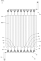
- FIG.1 is a plan view for describing a battery pack cooling device 10 according to example embodiments.
- FIG. 2 illustrates a branched connector 130 of FIG. 1 .
- FIG. 3 illustrates a directional connector 140 of FIG. 1 .
- FIG. 4 illustrates a connection pipe 150 of FIG. 1 .
- the battery pack cooling device 10 may include pipe assemblies 100 and a heat sink 200.
- the heat sink 200 may be configured to cool a heat source (e.g., a battery cell assembly) through direct or indirect thermal contact.
- the heat sink 200 may be a support plate configured to support a heating source (e.g., a plurality of battery cell assemblies).
- the heat sink 200 may be an upper cooling device disposed on a heating source (e.g., a plurality of battery cell assemblies) and covering the heating source (e.g., a plurality of battery cell assemblies).
- a thermal interface material TIM may be interposed between the heat sink 200 and a heat source (e.g., multiple battery cell assemblies).
- the heat sink 200 may be provided through an extrusion process.
- the heat sink 200 may include a plurality of cooling channels 200CH.
- Each of the plurality of cooling channels 200CH may provide a passage through which a cooling fluid flows.
- Each of the plurality of cooling channels 200CH may extend in an X-axis direction.
- each of the plurality of cooling channels 200CH in the X-axis direction may be referred to as an inlet and another end thereof in the X-axis direction may be referred to as an outlet.
- the plurality of cooling channels 200CH may be spaced apart from each other in the Y-axis direction.
- the heat sink 200 may further include cavities between the plurality of cooling channels 200CH. The cavities may extend in the X-axis direction.
- Each of the pipe assemblies 100 may include a main pipe 110, first to third branch pipes 121, 123, and 125, a plurality of branched connectors 130, a plurality of directional connectors 140, a plurality of connection pipes 150, and a plurality of cooling ports 161, 162, 163, 164, 165, 166, 167, 168, and 169.
- Each of the pipe assemblies 100 may be coupled to the heat sink 200.Each of the pipe assemblies 100 may be configured to distribute or collect a cooling fluid according to cooling design of the battery pack cooling device 10.
- the pipe assemblies 100 of the present embodiment may be configured according to a 3P (parallel)-3P (parallel) design. That is, the cooling ports 161, 162, and 163 connected in parallel may form a first group, the cooling ports 164, 165, and 166 connected in parallel may form a second group, and the cooling ports 167, 168, and 169 connected in parallel may form a third group.
- the first to third groups may be respectively connected to the first to third branch pipes 121, 123, and 125 connected in parallel to the main pipe 110.
- each of the pipe assemblies 100 may be configured according to the 3P-3P design including a parallel connection of two hierarchies.
- One of the pipe assemblies 100 may correspond to injection of a cooling fluid into the heat sink 200, and the other pipe assembly 100 may correspond to discharging of the cooling fluid from the heat sink 200.
- One of the pipe assemblies 100 may be configured to supply the cooling fluid to the heat sink 200, and the other pipe assembly 100 may be configured to discharge the cooling fluid flowing through the cooling channels 200CH of the heat sink 200.
- one of the pipe assemblies 100 may be referred to as a supply pipe assembly, and the other pipe assembly 100 may be referred to as a discharge pipe assembly.
- the supply pipe assembly may be connected to inlets of the plurality of cooling channels 200CH, and the discharge pipe assembly may be connected to outlets of the plurality of cooling channels 200CH.
- a relationship between elements of each of the pipe assemblies 100 described with respect to the discharge of the cooling fluid is substantially the same as a relationship between the elements of each of the pipe assemblies 100 described with respect to the supply of the cooling fluid, except for a direction of the flow of the cooling fluid. Therefore, even when a particular element of each of the pipe assemblies 100 is described with respect to the supply or discharge of the cooling fluid, those of ordinary skill in the art will be able to easily derive characteristics and properties of the particular element with respect to the supply or discharge of the cooling fluid, based on the above description.
- the main pipe 110 may be connected to a cooling fluid source (or a cooling fluid sink).
- the main pipe 110 may perform the overall supply of the cooling fluid to the heat sink 200 (or the overall discharge of the cooling fluid from the heat sink 200).
- Pipes of various paths and designs may be provided between the main pipe 110 and the cooling fluid source.
- the main pipe 110 may be connected to the first to third branch pipes 121, 123, and 125.
- the cooling fluid transferred to the main pipe 110 may be distributed to the first to third branch pipes 121, 123, and 125.
- the first to third branch pipes 121, 123, and 125 may be coupled to the main pipe 110 by a method such as welding and brazing.
- a first branch point 121P that is a node between the first branch pipe 121 and the main pipe 110 may be more distant from the heat sink 200 in the X-axis direction than a second branch point 123P that is a node between the second branch pipe 123 and the main pipe 110.
- the second branch point 123P that is a node between the second branch pipe 123 and the main pipe 110 may be more distant from the heat sink 200 in the X-axis direction than a third branch point 125P that is a node between the third branch pipe 125 and the main pipe 110.
- a length of the first branch pipe 121 in the Y-axis direction may be greater than a length of the second branch pipe 123 in the Y-axis direction.
- the length of the second branch pipe 123 in the Y-axis direction may be greater than a length the third branch pipe 125 in the Y-axis direction.
- the differences between supply (or discharge) paths of the cooling fluid through the first to third branch pipes 121, 123, and 125 may decrease and uniformity of cooling of the heat sink 200 may be achieved.
- each of the plurality of branched connectors 130 may include first and second pipe coupling parts 131 and 132, a port coupling part 133, and a port clamp 135.
- the plurality of branched connectors 130 may have a symmetric shape with respect to the port coupling part 133. Accordingly, the first and second pipe coupling parts 131 and 132 may have substantially the same shape. An angle ⁇ 1 between the first and second pipe coupling parts 131 and 132 may be greater than 90 degrees. The angle ⁇ 1 between the first and second pipe coupling parts 131 and 132 may be less than 180 degrees.
- Some of the plurality of branched connectors 130 may be connected to the first to third branch pipes 121, 123, and 125.
- the branched connectors 130 connected to the first to third branch pipes 121, 123, and 125 may be referred to as first branched connectors, based on a connection order.
- the first branched connectors may be connected to the cooling ports 161, 164, and 167.
- the first pipe coupling part 131 of each of the branched connectors 130 connected to the first to third branch pipes 121, 123, and 125 may be connected to the first to third branch pipes 121, 123, and 125.
- the second pipe coupling part 132 of each of the branched connectors 130 connected to the first to third branch pipes 121, 123, and 125 may be connected to the connection pipe 150.
- Each of the first and second pipe coupling parts 131 and 132 of the branched connectors 130 that are not connected to the first to third branch pipes 121, 123, and 125 may be connected to the connection pipes 150.
- the branched connectors 130 having the first and second pipe coupling parts 131 and 132 each is connected to the connection pipes 150 may be referred to as second branched connectors, based on a connection order.
- the second branched connectors may be connected to the cooling ports 162, 165, and 168.
- the cooling fluid supplied through the first pipe coupling parts 131 of the branched connectors 130 connected to the first to third branch pipes 121, 123, and 125 may flow to the second pipe coupling part 132 and the port coupling part 133.
- the cooling fluid introduced through the port coupling parts 133 of the branched connectors 130 connected to the first to third branch pipes 121, 123, and 125 may flow to the first and second pipe coupling parts 131 and 132.
- connection pipes 150 may each include a bent portion.
- a bending angle ⁇ 2 of the bent portion of each of the connection pipes 150 may be greater than 90 degrees.
- the bending angle ⁇ 2 of the bent portion of each of the connection pipes 150 may be less than 180 degrees.
- An angle ⁇ 1 between the first and second pipe coupling parts 131 and 132 may be substantially the same as the bending angle ⁇ 2 of the bent portion of each of the connection pipes 150.
- the plurality of directional connectors 140 may include a pipe coupling part 141, a port coupling part 143, and a port clamp 145. According to example embodiments, each of the plurality of directional connectors 140 may have an asymmetrical shape with respect to the port coupling part 143. According to example embodiments, the plurality of directional connectors 140 may include only one pipe coupling part 141. According to example embodiments, each of the plurality of directional connectors 140 may not include a branched structure.
- the inclusion of the branched structure should be understood to mean two or more outlets are provided to distribute a cooling fluid introduced from one inlet. That is, an element including the branched structure includes three or more paths.
- the plurality of directional connectors 140 may be configured to transmit an entire fluid introduced into the pipe coupling part 141 to the port coupling part 143. According to example embodiments, the plurality of directional connectors 140 may be configured to transmit an entire fluid introduced into the port coupling part 143 to the pipe coupling part 141. Accordingly, the fluid introduced into the pipe coupling part 141 may flow to the port coupling part 143 without branching, and the fluid introduced through the port coupling part 143 may flow to the pipe coupling part 141 without branching.
- the plurality of directional connectors 140 may be spaced apart from the plurality of branched connectors 130 with the connection pipes 150 interposed therebetween.
- the plurality of directional connectors 140 may be connected to connection pipes 150 connected to the second branched connectors.
- the pipe coupling parts 141 of the plurality of directional connectors 140 may be connected to the connection pipes 150.
- the plurality of branched connectors 130 and the connection pipes 150 may be fixed to each other by an insertion method or an interference fitting method.
- the plurality of directional connectors 140 and the connection pipes 150 may be fixed to each other by the insertion method or the interference fitting method.
- the plurality of cooling ports 161 to 169 may be connected to the plurality of cooling channels 200CH of the heat sink 200.
- the plurality of cooling ports 161 to 169 may be sequentially arranged. That is, a leading one among the plurality of cooling ports 161 to 169 may be closer to the main pipe 110 in the Y-axis direction than a following one among the plurality of cooling ports 161 to 169.
- the cooling port 161 is closer to the main pipe 110 than the cooling port 162.
- a cooling fluid supplied through the plurality of cooling ports 161 to 169 may flow along the plurality of cooling channels 200CH.
- the cooling fluid flowing along the plurality of cooling channels 200CH may be discharged through the plurality of cooling ports 161 to 169.
- the plurality of cooling ports 161, 162, 164, 165, 167, and 168 may be connected to the plurality of branched connectors 130.
- Each of the plurality of cooling ports 161, 162, 164, 165, 167, and 168 may be connected to the port coupling part 133 of one of the plurality of branched connectors 130.
- the port coupling part 133 of each of the plurality of branched connectors 130 may be connected to a corresponding one among the plurality of cooling ports 161, 162, 164, 165, 167, and 168.
- Each of the plurality of cooling ports 161, 162, 164, 165, 167, and 168 may be fixed by the port clamp 135 of one of the plurality of branched connectors 130.
- the port clamp 135 of each of the plurality of branched connectors 130 may fix a corresponding one among the plurality of cooling ports 161, 162, 164, 165, 167, and 168. Accordingly, each of the plurality of cooling ports 161, 162, 164, 165, 167, and 168 may not be welded or brazed with one of the plurality of branched connectors 130.
- the plurality of cooling ports 163, 166, and 169 may be connected to the plurality of directional connectors 140. Each of the plurality of cooling ports 163, 166, and 169 may be connected to the port coupling part 143 of one of the plurality of directional connectors 140. The port coupling part 143 of each of the plurality of directional connectors 140 may be connected to a corresponding one among the plurality of cooling ports 163, 166, and 169.
- Each of the plurality of cooling ports 163, 166, and 169 may be fixed by the port clamp 145 of one of the plurality of directional connectors 140.
- the port clamp 145 of each of the plurality of directional connectors 140 may fix a corresponding one among the plurality of cooling ports 163, 166, and 169.
- Each of the plurality of cooling ports 163, 166, and 169 may not be welded or brazed with one of the plurality of directional connectors 140.
- FIG. 5 is a diagram for describing a battery pack cooling device 11 according to other example embodiments.
- the battery pack cooling device 11 may include pipe assemblies 101 and a heat sink 200.
- the heat sink 200 is substantially the same as that described above with reference to FIGS. 1 to 4 .
- Each of the pipe assemblies 101 may include a main pipe 110, first to third branch pipes 121, 123, and 125, a plurality of directional connectors 140, a plurality of connection pipes 150, and a plurality of cooling ports 161 to 169.Each of the pipe assemblies 101 of the present embodiment may not include a plurality of branched connectors 130.
- the main pipe 110, the first to third branch pipes 121, 123, and 125, the plurality of directional connectors 140, the plurality of connection pipes 150, and the plurality of cooling ports 161 to 169 are substantially the same as those described above with reference to FIGS. 1 to 4 , except for a correlation between the plurality of directional connectors 140 and the plurality of connection pipes 150.
- the pipe assemblies 101 may be configured to distribute or collect a cooling fluid according to a cooling design of the battery pack cooling device 11. More specifically, the pipe assemblies 101 of the present embodiment may be configured according to a 3P-3S (series) design. That is, the cooling ports 161, 162, and 163 connected in series may form a first group, the cooling ports 164, 165, and 166 connected in series may form a second group, and the cooling ports 167, 168, and 169 connected in series may form a third group.
- the first to third groups may be respectively connected to the first to third branch pipes 121, 123, and 125 connected in parallel to the main pipe 110. Accordingly, the pipe assemblies 100 may be configured according to a 3P-3S design including a serial connection of one hierarchy and a parallel connection of one hierarchy.
- each of the plurality of cooling ports 161 to 169 may be connected to one of the plurality of directional connectors 140.
- a cooling fluid introduced into the cooling port 161 and flowing through the cooling channel 200CH may be transferred to the cooling channel 200CH connected to the cooling port 162 by one of the plurality of directional connectors 140.
- the cooling fluid flowing through the cooling channel 200CH connected to the cooling port 162 may be transferred to the cooling channel 200CH connected to the cooling port 163 by another of the plurality of directional connectors 140.
- the cooling fluid may be discharged from the heat sink 200 after sequentially flowing through the cooling channel 200CH connected to the cooling port 161, the cooling channel 200CH connected to the cooling port 162, and the cooling channel 200CH connected to the cooling port 163.
- serial connection of the cooling ports 164, 165, and 166 and the serial connection between the cooling ports 167, 168, and 169 are also similar to the serial connection of the cooling ports 161, 162, and 163 and thus a redundant description thereof is omitted here.
- FIG. 6 is a diagram for describing a battery pack cooling device 12 according to other example embodiments.
- the battery pack cooling device 12 may include pipe assemblies 102a and 102b and a heat sink 200.
- the heat sink 200 may include a plurality of cooling channels 200CH. Cooling channels connected in series among the plurality of cooling channels 200CH may be referred to as first cooling channels, and cooling channels connected in parallel among the plurality of cooling channels 200CH may be referred to as second cooling channels.
- Each of the pipe assemblies 102a and 102b may include a main pipe 110, first to third branch pipes 121, 123, and 125, a plurality of branched connectors 130, a plurality of directional connectors 140, a plurality of connection pipes 150, and a plurality of cooling ports 161 to 169.
- the cooling ports 164, 165, and 166 may be connected in series to each other, the cooling ports 167, 168, and 169 may be connected in series to each other, and the cooling ports 161, 162, and 163 may be connected in parallel to each other.
- Configurations of the cooling ports 164, 165, and 166 connected in series, the cooling ports 167, 168, and 169 connected in series, and the plurality of directional connectors 140 connected thereto and a correlation therebetween are similar to those described above with reference to FIG. 5 , and thus, a redundant description thereof is omitted here.
- cooling ports 161, 162, and 163 connected in parallel, the plurality of branched connectors 130 connected thereto, and the plurality of directional connectors 140 and a correlation therebetween are similar to those described above with reference to FIGS. 1 to 4 , and thus a redundant description thereof is omitted here.
- FIG. 7 is a diagram for describing a battery pack cooling device 13 according to other example embodiments.
- the battery pack cooling device 13 may include pipe assemblies 103 and a heat sink 200.
- the heat sink 200 is substantially the same as that described above with reference to FIGS. 1 to 4 .
- Each of the pipe assemblies 103 may include a main pipe 110, a plurality of branched connectors 130, a directional connector 140, a plurality of connection pipes 150, and a plurality of cooling ports 161 to 169.
- Each of the pipe assemblies 103 of the present embodiment may not include branch pipes connected to the main pipe 110.
- the plurality of cooling ports 161 to 169 of the pipe assemblies 103 according to the present embodiment may be connected in parallel.
- Each of the cooling ports 161 to 168 may be connected to each of the plurality of branched connectors 130.
- the plurality of connection pipes 150 may connect neighboring ones among the plurality of branched connectors 130 to each other or connect the plurality of connectors 130 and the directional connector 140.
- the cooling port 169 may be connected to the directional connector 140. Accordingly, each of the pipe assemblies 103 may be configured according to a 9P design (or 9P-1S design) including a parallel connection of one hierarchy.
- FIG. 8 is a diagram for describing a battery pack cooling device 14 according to other example embodiments.
- the battery pack cooling device 14 may include pipe assemblies 104 and a heat sink 200.
- the heat sink 200 is substantially the same as that described above with reference to FIGS. 1 to 4 .
- Each of the pipe assemblies 104 may include a main pipe 110, a directional connector 140, a plurality of connection pipes 150, and a plurality of cooling ports 161 to 169.
- Each of the pipe assemblies 104 of the present embodiment may not include branch pipes connected to the main pipe 110.
- Each of the pipe assemblies 104 of the present embodiment may not include branched connectors.
- the plurality of cooling ports 161 to 169 of the pipe assemblies 104 according to the present embodiment may be connected in series.
- the cooling ports 161 to 169 may be connected to the plurality of directional connectors 140.
- the plurality of connection pipes 150 may connect neighboring ones among the plurality of directional connectors 140. Accordingly, a path of a cooling fluid sequentially flowing through the cooling ports 161 to 169 may be formed.
- each of the pipe assemblies 104 may be configured according to the 9S design (or 9S-1S design) including a serial connection of one hierarchy.
- FIG. 9 is a diagram for describing a battery pack cooling device 15 according to other example embodiments.
- the battery pack cooling device 15 may include a system pipe SP, pipe assemblies 100, and heat sinks 200.
- the battery pack cooling device 15 may be a dual cooling device.
- the pipe assemblies 100 and the heat sinks 200 are the same as those described above with reference to FIGS. 1 to 4 , except that they are arranged in a double layer.
- the device pipe SP may be configured to supply a cooling fluid to the pipe assemblies 100 or discharge a cooling fluid transferred through the pipe assemblies 100.
- a lower one among the heat sinks 200 may be a support plate configured to support a heat source (e.g., a plurality of battery cell assemblies), and an upper one among the heat sinks 200 may be an upper cooling device placed above the heat source (e.g., the plurality of battery cell assemblies) and covering the heat source (e.g., the plurality of battery cell assemblies).
- a heat source e.g., a plurality of battery cell assemblies
- an upper cooling device placed above the heat source (e.g., the plurality of battery cell assemblies) and covering the heat source (e.g., the plurality of battery cell assemblies).
- FIG. 9 an embodiment of the battery pack cooling device 15 of FIG. 9 , in which four pipe assemblies 100 are replaced with the pipe assemblies 101 of FIG. 5 , the pipe assemblies 102a and 102b of FIG. 6 , the pipe assemblies 103 of FIG. 7 , or the pipe assemblies 104 of FIG. 8 .
- the pipe assemblies 100 of FIG. 1 may be connected to inlets of the heat sinks 200
- the pipe assemblies 101 of FIG. 5 may be connected to outlets of the heat sinks 200.
Landscapes
- Engineering & Computer Science (AREA)
- Manufacturing & Machinery (AREA)
- Chemical & Material Sciences (AREA)
- Chemical Kinetics & Catalysis (AREA)
- Electrochemistry (AREA)
- General Chemical & Material Sciences (AREA)
- General Engineering & Computer Science (AREA)
- Mechanical Engineering (AREA)
- Physics & Mathematics (AREA)
- Thermal Sciences (AREA)
- Secondary Cells (AREA)
- Battery Mounting, Suspending (AREA)
Abstract
Description
- The present invention relates to a battery pack cooling device. The present application claims the benefit of priority based on
Korean Patent Application No. 10-2022-0167119, filed on December 2, 2022 Korean Patent Application No. 10-2023-0035244, filed on March 17, 2023 - A secondary battery can be charged and discharged a plurality of times unlike a primary battery. Secondary batteries have been widely used as energy sources for various types of wireless devices such as handsets, laptop computers, and cordless vacuum cleaners. Recently, a main use of secondary batteries is moving from mobile devices to mobility, as manufacturing costs per unit capacity of secondary batteries drastically decrease due to improved energy density and economies of scale and a range of battery electric vehicles (BEVs) increases to the same level as fuel vehicles.
- As secondary batteries are used for mobility, the demand for the safety of secondary batteries is increasing. A driver's life may be in danger when an accident such as fire occurs in a secondary battery used for mobility and thus research on technology for enhancing the safety of secondary batteries is indispensable. In particular, cooling technology for maintaining temperature of a secondary battery in operation is directly related to the lifespan and performance of the secondary battery as well as the stability of the secondary battery, and thus, many studies are being conducted on cooling technology of secondary batteries.
- The present invention is directed to providing a battery pack cooling device with improved reliability.
- To address the above problem, embodiments of the present invention provide a battery pack cooling device. The battery pack cooling device includes a heat sink extending in a first direction and including a plurality of cooling channels spaced apart from each other in a second direction perpendicular to the first direction, and a pipe assembly coupled to the heat sink.
- The pipe assembly includes: a main pipe; a first branch pipe and a second branch pipe connected to the main pipe, wherein a first branch point that is a node between the first branch pipe and the main pipe is more distant from the heat sink than a second branch point that is a node between the second branch pipe and the main pipe; a plurality of branched connectors connected to the first branch pipe and the second branch pipe; a plurality of connection pipes connected to the plurality of branched connectors; a plurality of directional connectors spaced apart from the plurality of branched connectors with the plurality of connection pipes interposed therebetween and connected to the plurality of connection pipes; and a plurality of cooling ports configured to connect the plurality of branched connectors and the plurality of directional connectors to the plurality of cooling channels.
- Each of the plurality of branched connectors and the plurality of directional connectors may include a port clamp configured to fix one of the plurality of cooling ports.
- Each of the plurality of branched connectors and the plurality of directional connectors may include a port coupling part to be connected to one of the plurality of cooling ports.
- Each of the plurality of branched connectors may include first and second pipe coupling parts.
- Each of the first pipe coupling parts may be connected to the first and second branch pipes.
- Each of the second pipe coupling parts may be connected to the plurality of connection pipes.
- Each of the plurality of connection pipes may include a bent portion, and an angle between the first and second branch pipes may be the same as a bending angle of the bent part of each of the plurality of connection pipes.
- Each of the plurality of directional connectors may not include a branched structure.
- Each of the plurality of directional connectors may include only one pipe coupling part.
- A length of the first branch pipe in the second direction may be greater than a length of the second branch pipe in the second direction.
- Each of the plurality of branched connectors may include a port coupling part connected to a corresponding cooling port among the plurality of cooling ports.
- Each of the plurality of branched connectors may have a symmetrical shape with respect to the port coupling part.
- Each of the plurality of branched connectors may include a port coupling part connected to a corresponding cooling port among the plurality of cooling ports.
- Each of the plurality of branched connectors may have an asymmetrical shape with respect to the port coupling part.
- Example embodiments of the present invention provide a battery pack cooling device. The battery pack cooling device includes a heat sink with a plurality of cooling channels connected in series, and a pipe assembly coupled to the heat sink, in which the pipe assembly includes a plurality of cooling ports connected to the plurality of cooling channels, and a plurality of directional connectors each including a port coupling part connected to a corresponding cooling port among the plurality of cooling ports, a port clamp configured to fix the corresponding cooling port, and a pipe coupling part. The pipe coupling part of each of the plurality of directional connectors is connected to the connection pipe.
- Example embodiments of the present invention provide a battery pack cooling device. The battery pack cooling device includes a heat sink with a plurality of cooling channels connected in parallel, and a pipe assembly coupled to the heat sink, in which the pipe assembly includes a plurality of cooling ports connected to the plurality of cooling channels, a branched connector with a port coupling part connected to a corresponding cooling port among the plurality of cooling ports, a port clamp configured to fix the corresponding cooling port, a first pipe coupling part, and a second pipe coupling part.
- Example embodiments of the present invention provide a battery pack cooling device. The battery pack cooling device includes a heat sink with a plurality of first cooling channels connected in series and a plurality of second cooling channels connected in parallel, and a pipe assembly coupled to the heat sink, in which the pipe assembly includes a plurality of directional connectors connected to the plurality of first cooling channels and including a pipe coupling part, a branched connector connected to one of the plurality of second cooling channels and including a first pipe coupling part and a second pipe coupling part, and a plurality of connection pipes connected to one of the pipe coupling part, the first pipe coupling part, and the second pipe coupling part.
- The pipe coupling parts of the plurality of directional connectors may be connected to each other through one of the plurality of connection pipes.
- A battery pack cooling device according to example embodiments of the present invention includes branched connectors and a directional quick connector. Accordingly, a brazing process and a welding process are not required to configure the battery pack cooling device, and a quick cooling design may be implemented.
- Effects achievable from example embodiments of the present invention are not limited to the above-described effects, and other effects that are not described herein will be clearly derived and understood by those of ordinary skilled in the art to which the example embodiments of the present invention pertain from the following description. That is, unintended effects achieved when the example embodiments of the present invention are implemented are derivable by those of ordinary skilled in the art from the example embodiments of the present invention.
-
-
FIG. 1 is a plan view for describing a battery pack cooling device according to example embodiments. -
FIG. 2 illustrates a branched connector ofFIG. 1 . -
FIG. 3 illustrates a directional connector ofFIG. 1 . -
FIG. 4 illustrates a connection pipe ofFIG. 1 . -
FIG. 5 is a diagram for describing a battery pack cooling device according to other example embodiments. -
FIG. 6 is a diagram for describing a battery pack cooling device according to other example embodiments. -
FIG. 7 is a diagram for describing a battery pack cooling device according to other example embodiments. -
FIG. 8 is a diagram for describing a battery pack cooling device according to other example embodiments. -
FIG. 9 is a diagram for describing a battery pack cooling device according to other example embodiments. - Hereinafter, embodiments of the present invention will be described in detail with reference to the accompanying drawings. Before describing embodiments of the present invention, the terms or expressions used in the present specification and claims should not be construed as being limited to as generally understood or as defined in commonly used dictionaries, and should be understood according to meanings and concepts matching corresponding to the present invention on the basis of the principle that the inventor(s) of the application can appropriately define the terms or expressions to optimally explain the present invention.
- Therefore, embodiments set forth herein and configurations illustrated in the drawings are only embodiments of the present invention and do not reflect all the technical ideas of the present invention and thus it should be understood that various equivalents and modifications that replace the configurations would have been made at the filing date of the present application.
- Well-known configurations or functions related to describing the present invention are not described in detail when it is determined that they would obscure the subject matter of the present invention due to unnecessary detail.
- Because embodiments of the present invention are provided to more fully explain the present invention to those of ordinary skill in the art, the shapes, sizes, etc. of components illustrated in the drawings may be exaggerated, omitted, or schematically illustrated for clarity. Therefore, it should not be understood that the sizes or proportions of components fully reflect the actual sizes or proportions thereof.
-
FIG.1 is a plan view for describing a batterypack cooling device 10 according to example embodiments. -
FIG. 2 illustrates abranched connector 130 ofFIG. 1 . -
FIG. 3 illustrates adirectional connector 140 ofFIG. 1 . -
FIG. 4 illustrates aconnection pipe 150 ofFIG. 1 . - Referring to
FIGS. 1 to 4 , the batterypack cooling device 10 may includepipe assemblies 100 and aheat sink 200. According to example embodiments, theheat sink 200 may be configured to cool a heat source (e.g., a battery cell assembly) through direct or indirect thermal contact. As a non-limiting example, theheat sink 200 may be a support plate configured to support a heating source (e.g., a plurality of battery cell assemblies). As a non-limiting example, theheat sink 200 may be an upper cooling device disposed on a heating source (e.g., a plurality of battery cell assemblies) and covering the heating source (e.g., a plurality of battery cell assemblies).A thermal interface material (TIM) may be interposed between theheat sink 200 and a heat source (e.g., multiple battery cell assemblies). - As a non-limiting example, the
heat sink 200 may be provided through an extrusion process. According to example embodiments, theheat sink 200 may include a plurality of cooling channels 200CH. Each of the plurality of cooling channels 200CH may provide a passage through which a cooling fluid flows. Each of the plurality of cooling channels 200CH may extend in an X-axis direction. - One end of each of the plurality of cooling channels 200CH in the X-axis direction may be referred to as an inlet and another end thereof in the X-axis direction may be referred to as an outlet. The plurality of cooling channels 200CH may be spaced apart from each other in the Y-axis direction. The
heat sink 200 may further include cavities between the plurality of cooling channels 200CH. The cavities may extend in the X-axis direction. - Each of the
pipe assemblies 100 may include amain pipe 110, first tothird branch pipes branched connectors 130, a plurality ofdirectional connectors 140, a plurality ofconnection pipes 150, and a plurality of coolingports - Each of the
pipe assemblies 100 may be coupled to the heat sink 200.Each of thepipe assemblies 100 may be configured to distribute or collect a cooling fluid according to cooling design of the batterypack cooling device 10. Thepipe assemblies 100 of the present embodiment may be configured according to a 3P (parallel)-3P (parallel) design. That is, the coolingports ports ports third branch pipes main pipe 110. Thus, each of thepipe assemblies 100 may be configured according to the 3P-3P design including a parallel connection of two hierarchies. - One of the
pipe assemblies 100 may correspond to injection of a cooling fluid into theheat sink 200, and theother pipe assembly 100 may correspond to discharging of the cooling fluid from theheat sink 200. One of thepipe assemblies 100 may be configured to supply the cooling fluid to theheat sink 200, and theother pipe assembly 100 may be configured to discharge the cooling fluid flowing through the cooling channels 200CH of theheat sink 200. Accordingly, one of thepipe assemblies 100 may be referred to as a supply pipe assembly, and theother pipe assembly 100 may be referred to as a discharge pipe assembly. The supply pipe assembly may be connected to inlets of the plurality of cooling channels 200CH, and the discharge pipe assembly may be connected to outlets of the plurality of cooling channels 200CH. - A relationship between elements of each of the
pipe assemblies 100 described with respect to the discharge of the cooling fluid is substantially the same as a relationship between the elements of each of thepipe assemblies 100 described with respect to the supply of the cooling fluid, except for a direction of the flow of the cooling fluid. Therefore, even when a particular element of each of thepipe assemblies 100 is described with respect to the supply or discharge of the cooling fluid, those of ordinary skill in the art will be able to easily derive characteristics and properties of the particular element with respect to the supply or discharge of the cooling fluid, based on the above description. - The
main pipe 110 may be connected to a cooling fluid source (or a cooling fluid sink). Themain pipe 110 may perform the overall supply of the cooling fluid to the heat sink 200 (or the overall discharge of the cooling fluid from the heat sink 200). Pipes of various paths and designs may be provided between themain pipe 110 and the cooling fluid source. - The
main pipe 110 may be connected to the first tothird branch pipes main pipe 110 may be distributed to the first tothird branch pipes third branch pipes main pipe 110 by a method such as welding and brazing. - According to example embodiments, a
first branch point 121P that is a node between thefirst branch pipe 121 and themain pipe 110 may be more distant from theheat sink 200 in the X-axis direction than asecond branch point 123P that is a node between thesecond branch pipe 123 and themain pipe 110. According to example embodiments, thesecond branch point 123P that is a node between thesecond branch pipe 123 and themain pipe 110 may be more distant from theheat sink 200 in the X-axis direction than athird branch point 125P that is a node between thethird branch pipe 125 and themain pipe 110. - According to example embodiments, a length of the
first branch pipe 121 in the Y-axis direction may be greater than a length of thesecond branch pipe 123 in the Y-axis direction. According to example embodiments, the length of thesecond branch pipe 123 in the Y-axis direction may be greater than a length thethird branch pipe 125 in the Y-axis direction. - Accordingly, the differences between supply (or discharge) paths of the cooling fluid through the first to
third branch pipes heat sink 200 may be achieved. - According to example embodiments, each of the plurality of
branched connectors 130 may include first and secondpipe coupling parts port coupling part 133, and aport clamp 135. - The plurality of
branched connectors 130 may have a symmetric shape with respect to theport coupling part 133. Accordingly, the first and secondpipe coupling parts pipe coupling parts pipe coupling parts - Some of the plurality of
branched connectors 130 may be connected to the first tothird branch pipes branched connectors 130 connected to the first tothird branch pipes ports - The first
pipe coupling part 131 of each of the branchedconnectors 130 connected to the first tothird branch pipes third branch pipes pipe coupling part 132 of each of the branchedconnectors 130 connected to the first tothird branch pipes connection pipe 150. - Each of the first and second
pipe coupling parts connectors 130 that are not connected to the first tothird branch pipes connection pipes 150. Thebranched connectors 130 having the first and secondpipe coupling parts connection pipes 150 may be referred to as second branched connectors, based on a connection order. The second branched connectors may be connected to the coolingports - The cooling fluid supplied through the first
pipe coupling parts 131 of the branchedconnectors 130 connected to the first tothird branch pipes pipe coupling part 132 and theport coupling part 133. The cooling fluid introduced through theport coupling parts 133 of the branchedconnectors 130 connected to the first tothird branch pipes pipe coupling parts - The
connection pipes 150 may each include a bent portion. A bending angle θ2 of the bent portion of each of theconnection pipes 150 may be greater than 90 degrees. The bending angle θ2 of the bent portion of each of theconnection pipes 150 may be less than 180 degrees. An angle θ1 between the first and secondpipe coupling parts connection pipes 150. - According to example embodiments, the plurality of
directional connectors 140 may include apipe coupling part 141, aport coupling part 143, and aport clamp 145. According to example embodiments, each of the plurality ofdirectional connectors 140 may have an asymmetrical shape with respect to theport coupling part 143. According to example embodiments, the plurality ofdirectional connectors 140 may include only onepipe coupling part 141. According to example embodiments, each of the plurality ofdirectional connectors 140 may not include a branched structure. - Here, the inclusion of the branched structure should be understood to mean two or more outlets are provided to distribute a cooling fluid introduced from one inlet. That is, an element including the branched structure includes three or more paths.
- According to example embodiments, the plurality of
directional connectors 140 may be configured to transmit an entire fluid introduced into thepipe coupling part 141 to theport coupling part 143. According to example embodiments, the plurality ofdirectional connectors 140 may be configured to transmit an entire fluid introduced into theport coupling part 143 to thepipe coupling part 141. Accordingly, the fluid introduced into thepipe coupling part 141 may flow to theport coupling part 143 without branching, and the fluid introduced through theport coupling part 143 may flow to thepipe coupling part 141 without branching. - The plurality of
directional connectors 140 may be spaced apart from the plurality ofbranched connectors 130 with theconnection pipes 150 interposed therebetween. The plurality ofdirectional connectors 140 may be connected toconnection pipes 150 connected to the second branched connectors. Thepipe coupling parts 141 of the plurality ofdirectional connectors 140 may be connected to theconnection pipes 150. - The plurality of
branched connectors 130 and theconnection pipes 150 may be fixed to each other by an insertion method or an interference fitting method. The plurality ofdirectional connectors 140 and theconnection pipes 150 may be fixed to each other by the insertion method or the interference fitting method. - The plurality of cooling
ports 161 to 169 may be connected to the plurality of cooling channels 200CH of theheat sink 200. The plurality of coolingports 161 to 169 may be sequentially arranged. That is, a leading one among the plurality of coolingports 161 to 169 may be closer to themain pipe 110 in the Y-axis direction than a following one among the plurality of coolingports 161 to 169. For example, the coolingport 161 is closer to themain pipe 110 than the coolingport 162. - A cooling fluid supplied through the plurality of cooling
ports 161 to 169 may flow along the plurality of cooling channels 200CH. The cooling fluid flowing along the plurality of cooling channels 200CH may be discharged through the plurality of coolingports 161 to 169. - The plurality of cooling
ports branched connectors 130. Each of the plurality of coolingports port coupling part 133 of one of the plurality ofbranched connectors 130. Theport coupling part 133 of each of the plurality ofbranched connectors 130 may be connected to a corresponding one among the plurality of coolingports - Each of the plurality of cooling
ports port clamp 135 of one of the plurality ofbranched connectors 130. Theport clamp 135 of each of the plurality ofbranched connectors 130 may fix a corresponding one among the plurality of coolingports ports branched connectors 130. - The plurality of cooling
ports directional connectors 140. Each of the plurality of coolingports port coupling part 143 of one of the plurality ofdirectional connectors 140. Theport coupling part 143 of each of the plurality ofdirectional connectors 140 may be connected to a corresponding one among the plurality of coolingports - Each of the plurality of cooling
ports port clamp 145 of one of the plurality ofdirectional connectors 140. Theport clamp 145 of each of the plurality ofdirectional connectors 140 may fix a corresponding one among the plurality of coolingports ports directional connectors 140. -
FIG. 5 is a diagram for describing a batterypack cooling device 11 according to other example embodiments. - Referring to
FIG. 5 , the batterypack cooling device 11 may includepipe assemblies 101 and a heat sink 200.Theheat sink 200 is substantially the same as that described above with reference toFIGS. 1 to 4 . - Each of the
pipe assemblies 101 may include amain pipe 110, first tothird branch pipes directional connectors 140, a plurality ofconnection pipes 150, and a plurality of coolingports 161 to 169.Each of thepipe assemblies 101 of the present embodiment may not include a plurality ofbranched connectors 130. - The
main pipe 110, the first tothird branch pipes directional connectors 140, the plurality ofconnection pipes 150, and the plurality of coolingports 161 to 169 are substantially the same as those described above with reference toFIGS. 1 to 4 , except for a correlation between the plurality ofdirectional connectors 140 and the plurality ofconnection pipes 150. - The
pipe assemblies 101 may be configured to distribute or collect a cooling fluid according to a cooling design of the batterypack cooling device 11. More specifically, thepipe assemblies 101 of the present embodiment may be configured according to a 3P-3S (series) design. That is, the coolingports ports ports third branch pipes main pipe 110. Accordingly, thepipe assemblies 100 may be configured according to a 3P-3S design including a serial connection of one hierarchy and a parallel connection of one hierarchy. - In the present example, for the configuration of groups connected in series, each of the plurality of cooling
ports 161 to 169 may be connected to one of the plurality ofdirectional connectors 140. For example, a cooling fluid introduced into thecooling port 161 and flowing through the cooling channel 200CH may be transferred to the cooling channel 200CH connected to thecooling port 162 by one of the plurality ofdirectional connectors 140. The cooling fluid flowing through the cooling channel 200CH connected to thecooling port 162 may be transferred to the cooling channel 200CH connected to thecooling port 163 by another of the plurality ofdirectional connectors 140. Accordingly, the cooling fluid may be discharged from theheat sink 200 after sequentially flowing through the cooling channel 200CH connected to thecooling port 161, the cooling channel 200CH connected to thecooling port 162, and the cooling channel 200CH connected to thecooling port 163. - The serial connection of the cooling
ports ports ports -
FIG. 6 is a diagram for describing a battery pack cooling device 12 according to other example embodiments. - Referring to
FIG. 6 , the battery pack cooling device 12 may includepipe assemblies heat sink 200. - As described above with reference to
FIGS. 1 to 4 , theheat sink 200 may include a plurality of cooling channels 200CH. Cooling channels connected in series among the plurality of cooling channels 200CH may be referred to as first cooling channels, and cooling channels connected in parallel among the plurality of cooling channels 200CH may be referred to as second cooling channels. - Each of the
pipe assemblies main pipe 110, first tothird branch pipes branched connectors 130, a plurality ofdirectional connectors 140, a plurality ofconnection pipes 150, and a plurality of coolingports 161 to 169. The coolingports ports ports - Configurations of the cooling
ports ports directional connectors 140 connected thereto and a correlation therebetween are similar to those described above with reference toFIG. 5 , and thus, a redundant description thereof is omitted here. - In addition, configurations of the cooling
ports branched connectors 130 connected thereto, and the plurality ofdirectional connectors 140 and a correlation therebetween are similar to those described above with reference toFIGS. 1 to 4 , and thus a redundant description thereof is omitted here. -
FIG. 7 is a diagram for describing a battery pack cooling device 13 according to other example embodiments. - Referring to
FIG. 7 , the battery pack cooling device 13 may includepipe assemblies 103 and a heat sink 200.Theheat sink 200 is substantially the same as that described above with reference toFIGS. 1 to 4 . - Each of the
pipe assemblies 103 may include amain pipe 110, a plurality ofbranched connectors 130, adirectional connector 140, a plurality ofconnection pipes 150, and a plurality of coolingports 161 to 169. Each of thepipe assemblies 103 of the present embodiment may not include branch pipes connected to themain pipe 110. The plurality of coolingports 161 to 169 of thepipe assemblies 103 according to the present embodiment may be connected in parallel. - Each of the cooling
ports 161 to 168 may be connected to each of the plurality ofbranched connectors 130. The plurality ofconnection pipes 150 may connect neighboring ones among the plurality ofbranched connectors 130 to each other or connect the plurality ofconnectors 130 and thedirectional connector 140. The coolingport 169 may be connected to thedirectional connector 140. Accordingly, each of thepipe assemblies 103 may be configured according to a 9P design (or 9P-1S design) including a parallel connection of one hierarchy. -
FIG. 8 is a diagram for describing a battery pack cooling device 14 according to other example embodiments. - Referring to
FIG. 8 , the battery pack cooling device 14 may includepipe assemblies 104 and aheat sink 200. Theheat sink 200 is substantially the same as that described above with reference toFIGS. 1 to 4 . - Each of the
pipe assemblies 104 may include amain pipe 110, adirectional connector 140, a plurality ofconnection pipes 150, and a plurality of coolingports 161 to 169. Each of thepipe assemblies 104 of the present embodiment may not include branch pipes connected to themain pipe 110. Each of thepipe assemblies 104 of the present embodiment may not include branched connectors. The plurality of coolingports 161 to 169 of thepipe assemblies 104 according to the present embodiment may be connected in series. - The cooling
ports 161 to 169 may be connected to the plurality ofdirectional connectors 140. The plurality ofconnection pipes 150 may connect neighboring ones among the plurality ofdirectional connectors 140. Accordingly, a path of a cooling fluid sequentially flowing through the coolingports 161 to 169 may be formed. Accordingly, each of thepipe assemblies 104 may be configured according to the 9S design (or 9S-1S design) including a serial connection of one hierarchy. -
FIG. 9 is a diagram for describing a battery pack cooling device 15 according to other example embodiments. - According to example embodiments, the battery pack cooling device 15 may include a system pipe SP,
pipe assemblies 100, and heat sinks 200.The battery pack cooling device 15 may be a dual cooling device. - The
pipe assemblies 100 and theheat sinks 200 are the same as those described above with reference toFIGS. 1 to 4 , except that they are arranged in a double layer. The device pipe SP may be configured to supply a cooling fluid to thepipe assemblies 100 or discharge a cooling fluid transferred through thepipe assemblies 100. - A lower one among the
heat sinks 200 may be a support plate configured to support a heat source (e.g., a plurality of battery cell assemblies), and an upper one among theheat sinks 200 may be an upper cooling device placed above the heat source (e.g., the plurality of battery cell assemblies) and covering the heat source (e.g., the plurality of battery cell assemblies). - Those of ordinary skill in the art will be able to easily derive an embodiment of the battery pack cooling device 15 of
FIG. 9 , in which fourpipe assemblies 100 are replaced with thepipe assemblies 101 ofFIG. 5 , thepipe assemblies FIG. 6 , thepipe assemblies 103 ofFIG. 7 , or thepipe assemblies 104 ofFIG. 8 .In addition, it will be understood by those of ordinary skill in the art that there may be a different correlation between pipe assemblies disposed at opposite ends of each of the heat sinks 200.For example, thepipe assemblies 100 ofFIG. 1 may be connected to inlets of theheat sinks 200, and thepipe assemblies 101 ofFIG. 5 may be connected to outlets of the heat sinks 200. - The present invention has been described above in more detail with reference to the drawings, the embodiments, etc. However, the configurations illustrated in the drawings or embodiments described in the present specification are only embodiments of the present invention and do not reflect all the technical ideas of the present invention and thus it should be understood that various equivalents and modifications that replace the configurations would have been made at the filing date of the present application.
Claims (14)
- A battery pack cooling device comprising:a heat sink extending in a first direction and including a plurality of cooling channels spaced apart from each other in a second direction perpendicular to the first direction; anda pipe assembly coupled to the heat sink,wherein the pipe assembly includes:a main pipe;a first branch pipe and a second branch pipe connected to the main pipe, wherein a first branch point that is a node between the first branch pipe and the main pipe is more distant from the heat sink than a second branch point that is a node between the second branch pipe and the main pipe;a plurality of branched connectors connected to the first branch pipe and the second branch pipe;a plurality of connection pipes connected to the plurality of branched connectors;a plurality of directional connectors spaced apart from the plurality of branched connectors with the plurality of connection pipes interposed therebetween and connected to the plurality of connection pipes; anda plurality of cooling ports configured to connect the plurality of branched connectors and the plurality of directional connectors to the plurality of cooling channels.
- The battery pack cooling device of claim 1, wherein each of the plurality of branched connectors and the plurality of directional connectors includes a port clamp configured to fix one of the plurality of cooling ports.
- The battery pack cooling device of claim 1, wherein each of the plurality of branched connectors and the plurality of directional connectors includes a port coupling part to be connected to one of the plurality of cooling ports.
- The battery pack cooling device of claim 1, wherein each of the plurality of branched connectors includes first and second pipe coupling parts,each of the first pipe coupling parts is connected to the first and second branch pipes, andeach of the second pipe coupling parts is connected to the plurality of connection pipes.
- The battery pack cooling device of claim 4, wherein each of the plurality of connection pipes includes a bent portion, and
an angle between the first and second branch pipes is the same as a bending angle of the bent part of each of the plurality of connection pipes. - The battery pack cooling device of claim 1, wherein each of the plurality of directional connectors does not include a branched structure.
- The battery pack cooling device of claim 6, wherein each of the plurality of directional connectors includes only one pipe coupling part.
- The battery pack cooling device of claim 1, wherein a length of the first branch pipe in the second direction is greater than a length of the second branch pipe in the second direction.
- The battery pack cooling device of claim 1, wherein each of the plurality of branched connectors includes a port coupling part connected to a corresponding cooling port among the plurality of cooling ports, and
each of the plurality of branched connectors has a symmetrical shape with respect to the port coupling part. - The battery pack cooling device of claim 1, wherein each of the plurality of directional connectors includes a port coupling part connected to a corresponding cooling port among the plurality of cooling ports, and
each of the plurality of directional connectors has an asymmetrical shape with respect to the port coupling part. - A battery pack cooling device comprising:a heat sink including a plurality of cooling channels connected in series; anda pipe assembly coupled to the heat sink,wherein the pipe assembly includes:a plurality of cooling ports connected to the plurality of cooling channels; anda plurality of directional connectors each including a port coupling part connected to a corresponding cooling port among the plurality of cooling ports, a port clamp configured to fix the corresponding cooling port, and a pipe coupling part, andthe pipe coupling part of each of the plurality of directional connectors is connected to a connection pipe.
- A battery pack cooling device comprising:a heat sink including a plurality of cooling channels connected in parallel; anda pipe assembly coupled to the heat sink,wherein the pipe assembly includes:a plurality of cooling ports connected to the plurality of cooling channels;a branched connector including a port coupling part connected to a corresponding cooling port among the plurality of cooling ports, a port clamp configured to fix the corresponding cooling port, a first pipe coupling part, and a second pipe coupling part.
- A battery pack cooling device comprising:a heat sink including a plurality of first cooling channels connected in series and a plurality of second cooling channels connected in parallel; anda pipe assembly coupled to the heat sink,wherein the pipe assembly includes:a plurality of directional connectors connected to the plurality of first cooling channels and including a pipe coupling part;a branched connector connected to one of the plurality of second cooling channels and including a first pipe coupling part and a second pipe coupling part; anda plurality of connection pipes connected to one of the pipe coupling part, the first pipe coupling part, and the second pipe coupling part.
- The battery pack cooling device of claim 13, wherein
the pipe coupling parts of the plurality of directional connectors are connected to each other through one of the plurality of connection pipes.
Applications Claiming Priority (3)
| Application Number | Priority Date | Filing Date | Title |
|---|---|---|---|
| KR20220167119 | 2022-12-02 | ||
| KR1020230035244A KR20240082974A (en) | 2022-12-02 | 2023-03-17 | Apparatus for cooling battery pack |
| PCT/KR2023/019651 WO2024117847A1 (en) | 2022-12-02 | 2023-12-01 | Apparatus for cooling battery pack |
Publications (2)
| Publication Number | Publication Date |
|---|---|
| EP4456259A1 true EP4456259A1 (en) | 2024-10-30 |
| EP4456259A4 EP4456259A4 (en) | 2026-01-14 |
Family
ID=91324453
Family Applications (1)
| Application Number | Title | Priority Date | Filing Date |
|---|---|---|---|
| EP23898370.4A Pending EP4456259A4 (en) | 2022-12-02 | 2023-12-01 | DEVICE FOR COOLING A BATTERY PACK |
Country Status (4)
| Country | Link |
|---|---|
| US (1) | US20250183410A1 (en) |
| EP (1) | EP4456259A4 (en) |
| JP (2) | JP7791342B2 (en) |
| WO (1) | WO2024117847A1 (en) |
Families Citing this family (1)
| Publication number | Priority date | Publication date | Assignee | Title |
|---|---|---|---|---|
| KR20250009038A (en) * | 2023-07-10 | 2025-01-17 | 주식회사 엘지에너지솔루션 | Cooling device and battery pack including the same |
Family Cites Families (18)
| Publication number | Priority date | Publication date | Assignee | Title |
|---|---|---|---|---|
| JPH0783370A (en) * | 1993-09-10 | 1995-03-28 | Tokiko Yuki Kk | Coupling for hose |
| KR101367210B1 (en) * | 2011-12-09 | 2014-02-27 | 대한칼소닉주식회사 | Battery cell of heat sink unit |
| JP6697224B2 (en) | 2015-04-07 | 2020-05-20 | 昭和電工パッケージング株式会社 | Laminated electricity storage module |
| KR102044426B1 (en) * | 2015-12-04 | 2019-11-13 | 주식회사 엘지화학 | Indirect Cooling System Capable of Equally Cooling Battery Modules and Battery Pack Including the Same |
| CN207818838U (en) | 2017-09-30 | 2018-09-04 | 比亚迪股份有限公司 | Battery pack and battery thermal management system and vehicle |
| CN109149009B (en) * | 2018-09-12 | 2021-04-20 | 芜湖奇达动力电池系统有限公司 | High-efficiency low-temperature-difference integrated liquid-cooled battery system |
| KR102358425B1 (en) * | 2018-09-18 | 2022-02-03 | 주식회사 엘지에너지솔루션 | Battery module |
| CN209786138U (en) * | 2019-02-27 | 2019-12-13 | 合肥国轩高科动力能源有限公司 | A battery pack liquid cooling device |
| JP7339066B2 (en) | 2019-08-21 | 2023-09-05 | マツダ株式会社 | vehicle battery pack |
| CN211455900U (en) * | 2020-01-12 | 2020-09-08 | 南京创源天地动力科技有限公司 | Power battery package liquid cooling system architecture |
| KR20210127317A (en) * | 2020-04-14 | 2021-10-22 | 주식회사 엘지에너지솔루션 | Battery module and battery pack including the same |
| KR102953170B1 (en) | 2020-07-13 | 2026-04-15 | 램 리써치 코포레이션 | Seal venting in the substrate processing chamber |
| US12372181B2 (en) | 2021-01-29 | 2025-07-29 | Hutchinson Fluid Management Systems, Inc. | High tolerance quick connect coupling |
| KR20220144730A (en) * | 2021-04-20 | 2022-10-27 | 현대모비스 주식회사 | Cooling device for high voltage battery |
| CN214706049U (en) | 2021-06-08 | 2021-11-12 | 河北亚大汽车塑料制品有限公司 | Cooling pipeline and cooling system for battery pack |
| KR20220167119A (en) | 2021-06-11 | 2022-12-20 | 엘지전자 주식회사 | A display device and content recommendation method using the same |
| CN114725566A (en) | 2022-04-15 | 2022-07-08 | 东风柳州汽车有限公司 | Liquid cooling battery package and car |
| CN217762582U (en) | 2022-05-20 | 2022-11-08 | 宁德时代新能源科技股份有限公司 | Connecting pipe, connecting pipe assembly, battery and power consumption device |
-
2023
- 2023-12-01 JP JP2024546000A patent/JP7791342B2/en active Active
- 2023-12-01 EP EP23898370.4A patent/EP4456259A4/en active Pending
- 2023-12-01 WO PCT/KR2023/019651 patent/WO2024117847A1/en not_active Ceased
- 2023-12-01 US US18/835,276 patent/US20250183410A1/en active Pending
-
2025
- 2025-12-10 JP JP2025244545A patent/JP2026031754A/en active Pending
Also Published As
| Publication number | Publication date |
|---|---|
| JP2026031754A (en) | 2026-02-24 |
| JP2025504101A (en) | 2025-02-06 |
| JP7791342B2 (en) | 2025-12-23 |
| EP4456259A4 (en) | 2026-01-14 |
| WO2024117847A1 (en) | 2024-06-06 |
| US20250183410A1 (en) | 2025-06-05 |
Similar Documents
| Publication | Publication Date | Title |
|---|---|---|
| JP7359904B2 (en) | Refrigerant distributor for battery module housing and its manufacturing method | |
| CN117977088B (en) | Batteries and electrical devices | |
| US20250183410A1 (en) | Battery Pack Cooling Device | |
| CN116315267B (en) | Battery pack and energy storage system | |
| WO2022062605A1 (en) | Tray and battery pack having same | |
| WO2022062606A1 (en) | Battery pack | |
| CN219610564U (en) | Battery pack | |
| KR20240082974A (en) | Apparatus for cooling battery pack | |
| CN101728596A (en) | Battery and battery pack comprising the battery | |
| CN110207517A (en) | A kind of multiple working medium heat exchange core body and plate-fin heat exchanger | |
| CN118648158A (en) | Battery pack cooling system | |
| WO2025026142A1 (en) | Cooling device, heat exchanger, battery pack, and vehicle | |
| CN219610548U (en) | Liquid cooling system and battery pack | |
| CN111146470A (en) | fuel cell stack | |
| CN115911668A (en) | A liquid cooling system and battery pack | |
| KR102686568B1 (en) | Battery pack | |
| CN119852584B (en) | A power battery cooling system, battery pack and vehicle | |
| CN121355462B (en) | Battery module | |
| CN222214399U (en) | Battery cell assembly and battery pack | |
| CN116885234B (en) | Air flow distribution base suitable for multiple SOFC (solid oxide Fuel cell) pile modules | |
| CN220367912U (en) | Liquid cooling plate and cooling system | |
| JP5318058B2 (en) | Flow field plate assembly having a plurality of parallel flow paths | |
| CN224248700U (en) | Battery pack and heat transfer tube assembly | |
| US20260049775A1 (en) | Heat sink assembly | |
| CN224204165U (en) | Heat exchange system, battery pack and electric equipment |
Legal Events
| Date | Code | Title | Description |
|---|---|---|---|
| STAA | Information on the status of an ep patent application or granted ep patent |
Free format text: STATUS: THE INTERNATIONAL PUBLICATION HAS BEEN MADE |
|
| PUAI | Public reference made under article 153(3) epc to a published international application that has entered the european phase |
Free format text: ORIGINAL CODE: 0009012 |
|
| STAA | Information on the status of an ep patent application or granted ep patent |
Free format text: STATUS: REQUEST FOR EXAMINATION WAS MADE |
|
| 17P | Request for examination filed |
Effective date: 20240723 |
|
| AK | Designated contracting states |
Kind code of ref document: A1 Designated state(s): AL AT BE BG CH CY CZ DE DK EE ES FI FR GB GR HR HU IE IS IT LI LT LU LV MC ME MK MT NL NO PL PT RO RS SE SI SK SM TR |
|
| A4 | Supplementary search report drawn up and despatched |
Effective date: 20251211 |
|
| RIC1 | Information provided on ipc code assigned before grant |
Ipc: H01M 10/6552 20140101AFI20251205BHEP Ipc: H01M 10/6551 20140101ALI20251205BHEP Ipc: H01M 10/6556 20140101ALI20251205BHEP Ipc: H01M 10/613 20140101ALI20251205BHEP Ipc: H01M 10/6568 20140101ALI20251205BHEP Ipc: F16L 41/02 20060101ALI20251205BHEP Ipc: F28F 9/02 20060101ALI20251205BHEP |
|
| DAV | Request for validation of the european patent (deleted) | ||
| DAX | Request for extension of the european patent (deleted) | ||
| STAA | Information on the status of an ep patent application or granted ep patent |
Free format text: STATUS: EXAMINATION IS IN PROGRESS |
|
| 17Q | First examination report despatched |
Effective date: 20260319 |