EP4456223A1 - Battery with deformable metamaterial unit - Google Patents
Battery with deformable metamaterial unit Download PDFInfo
- Publication number
- EP4456223A1 EP4456223A1 EP23169778.0A EP23169778A EP4456223A1 EP 4456223 A1 EP4456223 A1 EP 4456223A1 EP 23169778 A EP23169778 A EP 23169778A EP 4456223 A1 EP4456223 A1 EP 4456223A1
- Authority
- EP
- European Patent Office
- Prior art keywords
- deformable
- metamaterial
- unit
- battery unit
- battery
- Prior art date
- Legal status (The legal status is an assumption and is not a legal conclusion. Google has not performed a legal analysis and makes no representation as to the accuracy of the status listed.)
- Granted
Links
Images


Classifications
-
- H—ELECTRICITY
- H01—ELECTRIC ELEMENTS
- H01M—PROCESSES OR MEANS, e.g. BATTERIES, FOR THE DIRECT CONVERSION OF CHEMICAL ENERGY INTO ELECTRICAL ENERGY
- H01M10/00—Secondary cells; Manufacture thereof
- H01M10/04—Construction or manufacture in general
-
- H—ELECTRICITY
- H01—ELECTRIC ELEMENTS
- H01M—PROCESSES OR MEANS, e.g. BATTERIES, FOR THE DIRECT CONVERSION OF CHEMICAL ENERGY INTO ELECTRICAL ENERGY
- H01M10/00—Secondary cells; Manufacture thereof
- H01M10/05—Accumulators with non-aqueous electrolyte
- H01M10/052—Li-accumulators
- H01M10/0525—Rocking-chair batteries, i.e. batteries with lithium insertion or intercalation in both electrodes; Lithium-ion batteries
-
- H—ELECTRICITY
- H01—ELECTRIC ELEMENTS
- H01M—PROCESSES OR MEANS, e.g. BATTERIES, FOR THE DIRECT CONVERSION OF CHEMICAL ENERGY INTO ELECTRICAL ENERGY
- H01M50/00—Constructional details or processes of manufacture of the non-active parts of electrochemical cells other than fuel cells, e.g. hybrid cells
- H01M50/40—Separators; Membranes; Diaphragms; Spacing elements inside cells
- H01M50/46—Separators, membranes or diaphragms characterised by their combination with electrodes
-
- H—ELECTRICITY
- H01—ELECTRIC ELEMENTS
- H01M—PROCESSES OR MEANS, e.g. BATTERIES, FOR THE DIRECT CONVERSION OF CHEMICAL ENERGY INTO ELECTRICAL ENERGY
- H01M50/00—Constructional details or processes of manufacture of the non-active parts of electrochemical cells other than fuel cells, e.g. hybrid cells
- H01M50/40—Separators; Membranes; Diaphragms; Spacing elements inside cells
- H01M50/471—Spacing elements inside cells other than separators, membranes or diaphragms; Manufacturing processes thereof
- H01M50/474—Spacing elements inside cells other than separators, membranes or diaphragms; Manufacturing processes thereof characterised by their position inside the cells
-
- H—ELECTRICITY
- H01—ELECTRIC ELEMENTS
- H01M—PROCESSES OR MEANS, e.g. BATTERIES, FOR THE DIRECT CONVERSION OF CHEMICAL ENERGY INTO ELECTRICAL ENERGY
- H01M50/00—Constructional details or processes of manufacture of the non-active parts of electrochemical cells other than fuel cells, e.g. hybrid cells
- H01M50/40—Separators; Membranes; Diaphragms; Spacing elements inside cells
- H01M50/471—Spacing elements inside cells other than separators, membranes or diaphragms; Manufacturing processes thereof
- H01M50/48—Spacing elements inside cells other than separators, membranes or diaphragms; Manufacturing processes thereof characterised by the material
-
- H—ELECTRICITY
- H01—ELECTRIC ELEMENTS
- H01M—PROCESSES OR MEANS, e.g. BATTERIES, FOR THE DIRECT CONVERSION OF CHEMICAL ENERGY INTO ELECTRICAL ENERGY
- H01M4/00—Electrodes
- H01M4/02—Electrodes composed of, or comprising, active material
- H01M2004/026—Electrodes composed of, or comprising, active material characterised by the polarity
- H01M2004/027—Negative electrodes
-
- H—ELECTRICITY
- H01—ELECTRIC ELEMENTS
- H01M—PROCESSES OR MEANS, e.g. BATTERIES, FOR THE DIRECT CONVERSION OF CHEMICAL ENERGY INTO ELECTRICAL ENERGY
- H01M2220/00—Batteries for particular applications
- H01M2220/20—Batteries in motive systems, e.g. vehicle, ship, plane
-
- Y—GENERAL TAGGING OF NEW TECHNOLOGICAL DEVELOPMENTS; GENERAL TAGGING OF CROSS-SECTIONAL TECHNOLOGIES SPANNING OVER SEVERAL SECTIONS OF THE IPC; TECHNICAL SUBJECTS COVERED BY FORMER USPC CROSS-REFERENCE ART COLLECTIONS [XRACs] AND DIGESTS
- Y02—TECHNOLOGIES OR APPLICATIONS FOR MITIGATION OR ADAPTATION AGAINST CLIMATE CHANGE
- Y02E—REDUCTION OF GREENHOUSE GAS [GHG] EMISSIONS, RELATED TO ENERGY GENERATION, TRANSMISSION OR DISTRIBUTION
- Y02E60/00—Enabling technologies; Technologies with a potential or indirect contribution to GHG emissions mitigation
- Y02E60/10—Energy storage using batteries
Definitions
- the present disclosure relates to a battery unit for storing electrical energy, a vehicle with at least one battery unit and/or a use of a deformable metamaterial unit configured to surround at least an anode of a battery unit.
- Known battery units may, for example, change their respective dimensions due to external influences and/or usage-related effects and/or effects during use, whereby the anode of a battery unit in particular may be affected. Thereby in particular in breathing-swelling behavior may occur. This change of the dimensions may provide a disadvantageous effect on at least the lifetime of a battery unit.
- a battery unit for storing electrical energy comprising: at least two electrodes, whereby one of the electrodes is an anode and one of the electrodes is a cathode; and at least one deformable metamaterial unit.
- the battery unit may for example be a battery of a vehicle preferably the battery unit may also be a battery for operating a vehicle. Furthermore, the at least two electrodes may therefore be configured to provide the energy of the battery, preferably to a vehicle.
- the battery unit may comprise many cells constrained in a battery(module) package.
- the contemporary solutions of battery units may exhibit a swelling behavior due to cycling.
- the cycling may comprise charging - discharge episodes but also environmental effects like temperature fluctuations as well as storage and calendar life. Cycling caused mechanical response of the battery may, therefore, impact the battery state of health through fatigue affecting battery cell constituents.
- the at least one deformable metamaterial unit may be a manufactured unit, which may for example be made of a certain material composition, for example the at least one deformable metamaterial unit may comprise manufactured materials, which may comprise optical, electrical or magnetic, mechanical properties that cannot be found in nature.
- the at least one deformable metamaterial unit may not derive its properties from the properties of the base materials, but from their newly designed structures.
- the at least one deformable metamaterial unit may also be referred to herein as a deformable metamaterial unit and/or a metamaterial unit.
- the at least one deformable metamaterial unit may be configured such that it may be compressed by at least one applied force and return to its precompression shape after the applied force is removed.
- deformable may also be understood as compressible. Therefore, the at least one deformable metamaterial unit may be configured such that its shape is reversibly and/or variable.
- the at least one deformable metamaterial unit may therefore be configured to counteract an occurring force, for example, to control a movement of the occurring mechanical response.
- the deformable metamaterial unit may for example counteract occurring forces in the battery unit.
- the at least one deformable metamaterial unit may also be configured to counteract an occurring moment and/or shear, for example, to control a movement due to the occurring mechanical response.
- the deformable metamaterial unit may for example counteract occurring swelling response in the battery unit.
- the at least one deformable metamaterial unit may be configured to alleviate mechanical response of batteries during cycling is provided.
- forces in the battery unit may also occur due to external influences, such as for example heat, cold, dryness and/or humidity, mechanical shocks, and/or due to aging of the battery unit as well as seasonal effects.
- the at least one deformable metamaterial unit layer may comprise interconnected suspension units.
- the interconnected suspension units may be arranged between the anode and a separator material, whereby a need for a support material may be excluded.
- the at least one deformable metamaterial unit may be arranged between the anode and a support element.
- the support element may be configured to unilaterally support the at least one deformable metamaterial unit, whereby, for example, a force applied to the at least one deformable metamaterial unit may be supported by the support element. Furthermore, the support element may be configured to be fixed in the battery unit or mechanically attached to separator material.
- the at least one deformable metamaterial unit may comprise a cylindrical structure formed of one or more circular elements.
- the at least one deformable metamaterial unit may comprise one, two, three, four, five or more circular elements which are configured to form the structure of the deformable metamaterial unit.
- the one or more circular elements may be formed by means of a plurality of cells comprising at least a first cell shape and a second cell shape, for example as subsets of the metamaterial unit.
- the cell shape may comprise a first cell shape formed of a first horizontal rib and a second horizontal rib connected by a first horizontal lying v and a second horizontal lying v mirrored about a vertical axis of the first cell shape.
- the cell shape may comprise a second cell shape formed of a first horizontal rib and a second horizontal rib connected by a first horizontal lying w and a second horizontal lying w mirrored about a vertical axis of the second cell shape, whereby a third horizontal rip may be connected the first horizontal lying w with the second horizontal lying w.
- the horizontal lying v or the horizontal lying w may be formed by means of corners, which comprise a rounded edge shape.
- the entire cell shape may comprise corners that have a rounded edge shape.
- the horizontal lying v or the horizontal lying w may be formed by means of corners, which comprise a sharp edge shape. Furthermore, the entire cell shape may comprise corners that have a sharp edge shape.
- the first cell shape and/or the second cell shape may be configured to be reversibly deformed by an applied force.
- the at least one deformable metamaterial unit may be produced by a nano engineering, stamping, weaving, rolling, laser cutting and/or water cutting and/or 3D printing method and/or 3D printing method.
- the at least one deformable metamaterial may also be produced by plastic welding, weaving, tissue knitting and/or stamped out of other continuum material.
- the at least one deformable metamaterial unit may has a length between 1 nanometer [nm] and 100 millimeter [mm]; and whereby the at least one deformable metamaterial unit may has diameter between 1 [nm] and 100 [mm].
- the at least one deformable metamaterial unit may has a length between 1 and 1000 [nm]; and whereby the at least one deformable metamaterial unit may has diameter between 1 and 1000 [nm].
- the at least one deformable metamaterial unit may has a length between 1 and 1000 micrometer [ ⁇ m]; and whereby the at least one deformable metamaterial unit may has diameter between 1 and 1000 [ ⁇ m].
- the at least one deformable metamaterial unit may has a length between 1 and 100 [mm]; and whereby the at least one deformable metamaterial unit may has diameter between 1 and 100 [mm].
- the at least one deformable metamaterial unit may be configured to control and limit an expansion of the at least of the anode.
- the at least one deformable metamaterial unit may be configured to limit and/or control at least a breathing-swelling behavior of the battery unit. Furthermore, the deformable metamaterial unit may be configured such that the at least breathing-swelling behavior can be controlled.
- the battery unit may comprise two, four or more, preferably eight, deformable metamaterial units surrounding the anode and/or the at least one deformable metamaterial unit may be formed as a continuous surface configured to surround the anode.
- the battery unit may comprise three, five, seven or more deformable metamaterial units surrounding the anode.
- the battery unit may also comprise a plurality of continuous surfaces configured to surround the anode metamaterial layer as a scaffolding.
- the battery unit may also comprise a plurality of continuous surfaces configured to surround the anode metamaterial layer as a scaffolding may be designed as metamaterial.
- the two, four or more, preferably eight, deformable metamaterial units may be equally arranged on the anode; and/or the deformable metamaterial unit may be formed as a continuous surface is equally arranged around the anode; and/or the two, four or more, preferably eight, deformable metamaterial units may be each arranged in spaced apart relationship; and/or the deformable metamaterial unit may be formed as a continuous surface, is wrapped around the anode in such a way that a first wrapping of the deformable metamaterial unit is spaced apart from a second wrapping of the deformable metamaterial unit.
- the arrangement of the two, four or more, preferably eight, deformable metamaterial units and/or the wrapping of the continuous surface with the scaffolding may be distributed over the length and/or diameter of the anode.
- the equal arrangement of the two, four or more, preferably eight, deformable metamaterial units and/or the continuous surface may be configured to limit and/or control the at least breathing-swelling behavior of the battery unit, in particular the anode, but alternatively on other electrode configurations as well as the cathode uniformly within the battery unit.
- the two, four or more, preferably eight, deformable metamaterial units and/or the continuous surface may be configured to limit and/or control the at least breathing-swelling behavior at least at the arranged position on the anode.
- the battery unit may further comprise a mesh unit may be configured to keep the two, four or more, preferably eight, deformable metamaterial units and/or the deformable metamaterial unit formed as a continuous surface in position.
- the mesh unit may for example be configured to surround the two, four or more, preferably eight, deformable metamaterial units and/or the deformable metamaterial unit formed as a continuous surface and/or to be embedded in the two, four or more, preferably eight, deformable metamaterial units and/or the deformable metamaterial unit formed as a continuous surface.
- the mesh unit may be configured to surround the two, four or more, preferably eight, deformable metamaterial units and/or the deformable metamaterial unit formed as a continuous surface in at least one part and to be embedded in the two, four or more, preferably eight, deformable metamaterial units and/or the deformable metamaterial unit formed as a continuous surface in another part.
- the battery unit may further comprise a support structure as a scaffolding configured to be integrated into and/or arranged around the mesh unit in a clockwise and/or counterclockwise direction.
- the support structure may be configured as a continuous surface that is, for example, wrapped around the battery unit.
- the support structure may be configured as a truss system.
- the support structure may be configured as a permeable, flexible, framework in order to hold the at least one metamaterial unit in place.
- the framework may be woven.
- the support structure may for example be at least partially made of metamaterial, whereby the support structure is not limited to being made of metamaterial.
- the battery unit may be a propulsion battery and/or the battery unit is configured as a solid-state battery.
- the at least two electrodes and/or the battery unit may comprise a silicon material, graphite material and/or lithium-ion material.
- the at least two electrodes and/or the battery unit may comprise nickel and/or sodium material.
- the lithium-ion material may be in any phase form, for example, liquid, solid, gas and/or plasma.
- a further aspect of the present disclosure relates to a vehicle with at least one disclosed battery unit.
- a further aspect of the present disclosure relates to a use of a deformable metamaterial unit configured to surround at least an anode of the disclosed battery unit.
- Fig. 1 shows a schematic illustration showing an overview of an anode of the disclosed battery unit 10 for storing electrical energy comprising: at least two electrodes, whereby one of the electrodes is an anode 12 and one of the electrodes is a cathode; and eight deformable metamaterial units 14 surround the anode 12.
- the eight deformable metamaterial units 14 are equally arranged on the anode 12 as well as the eight deformable metamaterial units 14 are each arranged in spaced apart relationship.
- the battery unit 10 is further comprising a mesh unit 16 configured to keep the eight deformable metamaterial units 14 in position.
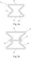
- Figs. 2a and 2b show a schematic illustration showing a first and a second view of a behavior of the at least one deformable metamaterial unit 14, whereby the at least one deformable metamaterial unit 14 is configured to comprise a non-deformed form as shown in Fig. 2a as well as to change into a deformed form by a force applied for example from above as shown in Fig. 2b .
- the at least one deformable metamaterial unit is configured to switch between the non-deformed shape and the deformed shape.
- Fig. 3a shows a schematic illustration showing a first example of a cell shape of circular elements of the disclosed deformable metamaterial unit, whereby a first cell shape 18 is formed of two horizontal ribs 20, 22 connected by a first horizontal lying v 24 and a second horizontal lying v 26 mirrored about a vertical axis of the first cell shape.
- Fig. 3b sows a schematic illustration showing a second example of a cell shape of circular elements of the disclosed deformable metamaterial unit, whereby a second cell shape 19 is formed of two horizontal ribs 20, 22 connected by a first horizontal lying w 28 and a second horizontal lying w 30 mirrored about a vertical axis of the second cell shape, whereby a third horizontal rip 32 connect the first horizontal lying w 28 with the second horizontal lying w 30.
- Figs. 3a and 3b show the horizontal lying v and the horizontal lying w be formed by means of corners, which comprise a rounded edge shape. Furthermore, the entire cell shape comprises corners that have a rounded edge shape.
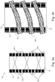
- Figs. 4a, 4b , 4c and 4d show a schematic illustration showing a first, second, third and fourth example of a structure of the disclosed deformable metamaterial unit 14, whereby a cylindrical structure of the deformable metamaterial unit 14 is formed by five circular elements 34.
- the five circular elements 34 are formed of a plurality of interconnected cells of a first cell shape and/or a second cell shape according to Figs. 3a and/or 3b.
- Figs. 4a, 4b , 4c and 4d each show different configurations of the respective circular elements 34 with the corresponding cell shapes.
- the deformable metamaterial unit 14 comprises a length (L) and a diameter (D), whereby in this embodiment, the metamaterial unit 14 comprises a ratio between the length and the diameter of 4 to 1.
- Fig. 5a shows a schematic illustration showing an example of a support structure of the disclosed deformable metamaterial unit 14 of Fig. 1 , whereby twenty-four deformable metamaterial units 14 are surrounding the anode 12 and are supported by the mesh unit 16.
- Fig. 5a shows a first support structure 36.1 and a second support structure 36.2 formed as a scaffolding configured to be integrated into and/or arranged around the mesh unit 16.
- first support structure 36.1 is integrated into and/or arranged around the mesh unit 16 in a clockwise direction.
- second support structure 36.2 is integrated into and/or arranged around the mesh unit 16 in a counterclockwise direction.
- Fig. 5b shows a schematic illustration showing the example of the scaffolding structure of Fig. 5a in a more detailed view, whereby in particular the second support structure 36.2 is shown in more detail, in such a way that an internal structure of the second support structure 36.2 is shown.
- the second support structure 36.2 comprises a structure similar to the structure of the metamaterial units 14.
Landscapes
- Chemical & Material Sciences (AREA)
- Chemical Kinetics & Catalysis (AREA)
- Electrochemistry (AREA)
- General Chemical & Material Sciences (AREA)
- Engineering & Computer Science (AREA)
- Manufacturing & Machinery (AREA)
- Materials Engineering (AREA)
- Battery Mounting, Suspending (AREA)
Abstract
Description
- The present disclosure relates to a battery unit for storing electrical energy, a vehicle with at least one battery unit and/or a use of a deformable metamaterial unit configured to surround at least an anode of a battery unit.
- Known battery units may, for example, change their respective dimensions due to external influences and/or usage-related effects and/or effects during use, whereby the anode of a battery unit in particular may be affected. Thereby in particular in breathing-swelling behavior may occur. This change of the dimensions may provide a disadvantageous effect on at least the lifetime of a battery unit.
- In view of this, it is found that a further need exists to provide an improved battery unit for storing electrical energy.
- In the view of the above, it is an object of the present disclosure to provide an improved battery unit for storing electrical energy.
- The problem is at least partially solved or alleviated by the subject matter of the independent claims of the present disclosure, whereby further examples are incorporated in the dependent claims.
- According to a first aspect, a battery unit for storing electrical energy, comprising: at least two electrodes, whereby one of the electrodes is an anode and one of the electrodes is a cathode; and at least one deformable metamaterial unit.
- The battery unit may for example be a battery of a vehicle preferably the battery unit may also be a battery for operating a vehicle. Furthermore, the at least two electrodes may therefore be configured to provide the energy of the battery, preferably to a vehicle.
- Furthermore, the battery unit may comprise many cells constrained in a battery(module) package.
- The contemporary solutions of battery units, in particular Li-ion battery units, may exhibit a swelling behavior due to cycling. The cycling may comprise charging - discharge episodes but also environmental effects like temperature fluctuations as well as storage and calendar life. Cycling caused mechanical response of the battery may, therefore, impact the battery state of health through fatigue affecting battery cell constituents.
- The at least one deformable metamaterial unit may be a manufactured unit, which may for example be made of a certain material composition, for example the at least one deformable metamaterial unit may comprise manufactured materials, which may comprise optical, electrical or magnetic, mechanical properties that cannot be found in nature. For example, the at least one deformable metamaterial unit may not derive its properties from the properties of the base materials, but from their newly designed structures.
- The at least one deformable metamaterial unit may also be referred to herein as a deformable metamaterial unit and/or a metamaterial unit.
- For example, the at least one deformable metamaterial unit may be configured such that it may be compressed by at least one applied force and return to its precompression shape after the applied force is removed. For example, deformable may also be understood as compressible. Therefore, the at least one deformable metamaterial unit may be configured such that its shape is reversibly and/or variable.
- The at least one deformable metamaterial unit may therefore be configured to counteract an occurring force, for example, to control a movement of the occurring mechanical response. In this respect, the deformable metamaterial unit may for example counteract occurring forces in the battery unit.
- Therefore, the at least one deformable metamaterial unit may also be configured to counteract an occurring moment and/or shear, for example, to control a movement due to the occurring mechanical response. In this respect, the deformable metamaterial unit may for example counteract occurring swelling response in the battery unit.
- Furthermore, the at least one deformable metamaterial unit may be configured to alleviate mechanical response of batteries during cycling is provided.
- For example, forces in the battery unit may also occur due to external influences, such as for example heat, cold, dryness and/or humidity, mechanical shocks, and/or due to aging of the battery unit as well as seasonal effects.
- In an implementation, the at least one deformable metamaterial unit layer may comprise interconnected suspension units.
- The interconnected suspension units may be arranged between the anode and a separator material, whereby a need for a support material may be excluded.
- In another implementation, the at least one deformable metamaterial unit may be arranged between the anode and a support element.
- The support element may be configured to unilaterally support the at least one deformable metamaterial unit, whereby, for example, a force applied to the at least one deformable metamaterial unit may be supported by the support element. Furthermore, the support element may be configured to be fixed in the battery unit or mechanically attached to separator material.
- In an implementation, the at least one deformable metamaterial unit may comprise a cylindrical structure formed of one or more circular elements.
- The at least one deformable metamaterial unit may comprise one, two, three, four, five or more circular elements which are configured to form the structure of the deformable metamaterial unit.
- In an implementation, the one or more circular elements may be formed by means of a plurality of cells comprising at least a first cell shape and a second cell shape, for example as subsets of the metamaterial unit.
- The cell shape may comprise a first cell shape formed of a first horizontal rib and a second horizontal rib connected by a first horizontal lying v and a second horizontal lying v mirrored about a vertical axis of the first cell shape.
- Furthermore, the cell shape may comprise a second cell shape formed of a first horizontal rib and a second horizontal rib connected by a first horizontal lying w and a second horizontal lying w mirrored about a vertical axis of the second cell shape, whereby a third horizontal rip may be connected the first horizontal lying w with the second horizontal lying w.
- For example, the horizontal lying v or the horizontal lying w may be formed by means of corners, which comprise a rounded edge shape. Furthermore, the entire cell shape may comprise corners that have a rounded edge shape.
- In another embodiment, the horizontal lying v or the horizontal lying w may be formed by means of corners, which comprise a sharp edge shape. Furthermore, the entire cell shape may comprise corners that have a sharp edge shape.
- The first cell shape and/or the second cell shape may be configured to be reversibly deformed by an applied force.
- In an implementation, the at least one deformable metamaterial unit may be produced by a nano engineering, stamping, weaving, rolling, laser cutting and/or water cutting and/or 3D printing method and/or 3D printing method.
- Furthermore, for example, traditional manufacturing processes such as stamping, rolling, laser cutting and/or water cutting may also be used to produce the at least one deformable metamaterial unit.
- In some examples, the at least one deformable metamaterial may also be produced by plastic welding, weaving, tissue knitting and/or stamped out of other continuum material.
- In an implementation, the at least one deformable metamaterial unit may has a length between 1 nanometer [nm] and 100 millimeter [mm]; and whereby the at least one deformable metamaterial unit may has diameter between 1 [nm] and 100 [mm].
- In an example, the at least one deformable metamaterial unit may has a length between 1 and 1000 [nm]; and whereby the at least one deformable metamaterial unit may has diameter between 1 and 1000 [nm].
- In another example, the at least one deformable metamaterial unit may has a length between 1 and 1000 micrometer [µm]; and whereby the at least one deformable metamaterial unit may has diameter between 1 and 1000 [µm].
- In another example, the at least one deformable metamaterial unit may has a length between 1 and 100 [mm]; and whereby the at least one deformable metamaterial unit may has diameter between 1 and 100 [mm].
- In an implementation, the at least one deformable metamaterial unit may be configured to control and limit an expansion of the at least of the anode.
- The at least one deformable metamaterial unit may be configured to limit and/or control at least a breathing-swelling behavior of the battery unit. Furthermore, the deformable metamaterial unit may be configured such that the at least breathing-swelling behavior can be controlled.
- In an implementation, the battery unit may comprise two, four or more, preferably eight, deformable metamaterial units surrounding the anode and/or the at least one deformable metamaterial unit may be formed as a continuous surface configured to surround the anode.
- Furthermore, the battery unit may comprise three, five, seven or more deformable metamaterial units surrounding the anode.
- In an example, the battery unit may also comprise a plurality of continuous surfaces configured to surround the anode metamaterial layer as a scaffolding.
- In an example, the battery unit may also comprise a plurality of continuous surfaces configured to surround the anode metamaterial layer as a scaffolding may be designed as metamaterial.
- In an implementation, the two, four or more, preferably eight, deformable metamaterial units may be equally arranged on the anode; and/or the deformable metamaterial unit may be formed as a continuous surface is equally arranged around the anode; and/or the two, four or more, preferably eight, deformable metamaterial units may be each arranged in spaced apart relationship; and/or the deformable metamaterial unit may be formed as a continuous surface, is wrapped around the anode in such a way that a first wrapping of the deformable metamaterial unit is spaced apart from a second wrapping of the deformable metamaterial unit.
- The arrangement of the two, four or more, preferably eight, deformable metamaterial units and/or the wrapping of the continuous surface with the scaffolding may be distributed over the length and/or diameter of the anode.
- The equal arrangement of the two, four or more, preferably eight, deformable metamaterial units and/or the continuous surface may be configured to limit and/or control the at least breathing-swelling behavior of the battery unit, in particular the anode, but alternatively on other electrode configurations as well as the cathode uniformly within the battery unit.
- The two, four or more, preferably eight, deformable metamaterial units and/or the continuous surface may be configured to limit and/or control the at least breathing-swelling behavior at least at the arranged position on the anode.
- In an implementation, the battery unit may further comprise a mesh unit may be configured to keep the two, four or more, preferably eight, deformable metamaterial units and/or the deformable metamaterial unit formed as a continuous surface in position.
- The mesh unit may for example be configured to surround the two, four or more, preferably eight, deformable metamaterial units and/or the deformable metamaterial unit formed as a continuous surface and/or to be embedded in the two, four or more, preferably eight, deformable metamaterial units and/or the deformable metamaterial unit formed as a continuous surface. In an example, the mesh unit may be configured to surround the two, four or more, preferably eight, deformable metamaterial units and/or the deformable metamaterial unit formed as a continuous surface in at least one part and to be embedded in the two, four or more, preferably eight, deformable metamaterial units and/or the deformable metamaterial unit formed as a continuous surface in another part.
- In an implementation, the battery unit may further comprise a support structure as a scaffolding configured to be integrated into and/or arranged around the mesh unit in a clockwise and/or counterclockwise direction.
- The support structure may be configured as a continuous surface that is, for example, wrapped around the battery unit. For example, the support structure may be configured as a truss system.
- Further, the support structure may be configured as a permeable, flexible, framework in order to hold the at least one metamaterial unit in place. Additionally, the framework may be woven.
- Furthermore, the support structure may for example be at least partially made of metamaterial, whereby the support structure is not limited to being made of metamaterial.
- In an implementation, the battery unit may be a propulsion battery and/or the battery unit is configured as a solid-state battery.
- In an implementation, the at least two electrodes and/or the battery unit may comprise a silicon material, graphite material and/or lithium-ion material.
- In other embodiments, the at least two electrodes and/or the battery unit may comprise nickel and/or sodium material.
- The lithium-ion material may be in any phase form, for example, liquid, solid, gas and/or plasma.
- For example, other materials may also be conceivable if they are configured in order to form electrodes of a battery and/or a battery unit.
- A further aspect of the present disclosure relates to a vehicle with at least one disclosed battery unit.
- A further aspect of the present disclosure relates to a use of a deformable metamaterial unit configured to surround at least an anode of the disclosed battery unit.
- In the following, the disclosure is described exemplarily with reference to the enclosed figures, in which:
- Fig. 1
- is a schematic illustration showing an overview of an anode of the disclosed battery unit for storing electrical energy;
- Fig. 2a
- is a schematic illustration showing a first view of a behavior of the at least one deformable metamaterial unit;
- Fig. 2b
- is a schematic illustration showing a second view of a behavior of the at least one deformable metamaterial unit of
Fig. 2a ; - Fig. 3a
- is a schematic illustration showing a first example of a cell shape of circular elements of the disclosed deformable metamaterial unit;
- Fig. 3b
- is a schematic illustration showing a second example of a cell shape of circular elements of the disclosed deformable metamaterial unit;
- Fig. 4a
- is a schematic illustration showing a first example of a structure of the disclosed deformable metamaterial unit;
- Fig. 4b
- is a schematic illustration showing a second example of a structure of the disclosed deformable metamaterial unit;
- Fig. 4c
- is a schematic illustration showing a third example of a structure of the disclosed deformable metamaterial unit;
- Fig. 4d
- is a schematic illustration showing a fourth example of a structure of the disclosed deformable metamaterial unit;
- Fig. 5a
- is a schematic illustration showing an example of a scaffolding structure of the disclosed deformable metamaterial unit of
Fig.1 ; and - Fig. 5b
- is a schematic illustration showing the example of the scaffolding structure of Fig. 5a in a more detailed view.
- Notably, the figures are merely schematic representations and serve only to illustrate examples of the present disclosure. Identical or equivalent elements are in principle provided with the same reference signs.
-
Fig. 1 shows a schematic illustration showing an overview of an anode of the disclosedbattery unit 10 for storing electrical energy comprising: at least two electrodes, whereby one of the electrodes is ananode 12 and one of the electrodes is a cathode; and eightdeformable metamaterial units 14 surround theanode 12. - Furthermore, the eight
deformable metamaterial units 14 are equally arranged on theanode 12 as well as the eightdeformable metamaterial units 14 are each arranged in spaced apart relationship. - Further, the
battery unit 10 is further comprising amesh unit 16 configured to keep the eightdeformable metamaterial units 14 in position. -
Figs. 2a and 2b show a schematic illustration showing a first and a second view of a behavior of the at least onedeformable metamaterial unit 14, whereby the at least onedeformable metamaterial unit 14 is configured to comprise a non-deformed form as shown inFig. 2a as well as to change into a deformed form by a force applied for example from above as shown inFig. 2b . - Thereby, the at least one deformable metamaterial unit is configured to switch between the non-deformed shape and the deformed shape.
-
Fig. 3a shows a schematic illustration showing a first example of a cell shape of circular elements of the disclosed deformable metamaterial unit, whereby afirst cell shape 18 is formed of twohorizontal ribs v 24 and a second horizontal lyingv 26 mirrored about a vertical axis of the first cell shape. -
Fig. 3b sows a schematic illustration showing a second example of a cell shape of circular elements of the disclosed deformable metamaterial unit, whereby asecond cell shape 19 is formed of twohorizontal ribs w 28 and a second horizontal lyingw 30 mirrored about a vertical axis of the second cell shape, whereby a thirdhorizontal rip 32 connect the first horizontal lyingw 28 with the second horizontal lyingw 30. -
Figs. 3a and 3b show the horizontal lying v and the horizontal lying w be formed by means of corners, which comprise a rounded edge shape. Furthermore, the entire cell shape comprises corners that have a rounded edge shape. -
Figs. 4a, 4b , 4c and 4d show a schematic illustration showing a first, second, third and fourth example of a structure of the discloseddeformable metamaterial unit 14, whereby a cylindrical structure of thedeformable metamaterial unit 14 is formed by fivecircular elements 34. - Furthermore, the five
circular elements 34 are formed of a plurality of interconnected cells of a first cell shape and/or a second cell shape according toFigs. 3a and/or 3b. Thereby,Figs. 4a, 4b , 4c and 4d each show different configurations of the respectivecircular elements 34 with the corresponding cell shapes. - Further, the
deformable metamaterial unit 14 comprises a length (L) and a diameter (D), whereby in this embodiment, themetamaterial unit 14 comprises a ratio between the length and the diameter of 4 to 1. - Fig. 5a shows a schematic illustration showing an example of a support structure of the disclosed
deformable metamaterial unit 14 ofFig. 1 , whereby twenty-fourdeformable metamaterial units 14 are surrounding theanode 12 and are supported by themesh unit 16. - In addition, Fig. 5a shows a first support structure 36.1 and a second support structure 36.2 formed as a scaffolding configured to be integrated into and/or arranged around the
mesh unit 16. - Furthermore, the first support structure 36.1 is integrated into and/or arranged around the
mesh unit 16 in a clockwise direction. Further, the second support structure 36.2 is integrated into and/or arranged around themesh unit 16 in a counterclockwise direction. - Fig. 5b shows a schematic illustration showing the example of the scaffolding structure of Fig. 5a in a more detailed view, whereby in particular the second support structure 36.2 is shown in more detail, in such a way that an internal structure of the second support structure 36.2 is shown.
- Thereby, the second support structure 36.2comprises a structure similar to the structure of the
metamaterial units 14. - Other variations to the disclosed examples may be understood and effected by those skilled in the art in practicing the claimed subject matter, from the study of the figures, the disclosure, and the appended claims. In particular, respective parts/functions of the respective example described above may also be combined with each other. In particular, the present disclosure is not limited to specific modules, vehicle functions, user interfaces, user interface areas/fields and/or communication methods. In the claims, the word "comprising" does not exclude other elements or steps and the indefinite article "a" or "an" does not exclude a plurality. The mere fact that certain measures are recited in mutually different dependent claims does not indicate that a combination of these measures may not be used to advantage. Any reference signs in the claims should not be construed as limiting the scope of the claims.
-
- 10
- battery unit
- 12
- anode
- 14
- deformable metamaterial unit
- 16
- mesh unit
- 18
- first cell shape
- 19
- second cell shape
- 20
- first horizontal rib
- 22
- second horizontal rib
- 24
- first lying v
- 26
- second lying v
- 28
- first lying w
- 30
- second lying w
- 32
- third horizontal rip
- 34
- circular elements
- 36.1
- first support structure
- 36.2
- second support structure
- L
- length
- D
- diameter
Claims (15)
- Battery unit for storing electrical energy, comprising:at least two electrodes, whereby one of the electrodes is an anode (12) and one of the electrodes is a cathode; andat least one deformable metamaterial unit (14).
- The battery unit according to claim 1, whereby the at least one deformable metamaterial unit (14) comprise at least one layer with interconnected suspension units.
- The battery unit according to claim 1 or claim 2, whereby the at least one deformable metamaterial unit (14) comprises a cylindrical structure formed of one or more circular elements (34).
- The battery unit according to any one of the preceding claims, whereby the one or more circular elements (34) are formed by means of a plurality of cells comprising at least a first cell shape (18) and/or a second cell shape (19).
- The battery unit according to any one of the preceding claims, whereby the at least one deformable metamaterial unit (14) is produced by a nano engineering, stamping, weaving, rolling, laser cutting and/or water cutting and/or 3D printing method.
- The battery unit according to any one of the preceding claims, whereby the at least one deformable metamaterial unit (14) has a length between 1 [nm] and 100 [mm]; and whereby the at least one deformable metamaterial unit (14) has diameter between 1 [nm] and 100 [mm].
- The battery unit according to any one of the preceding claims, whereby the at least one deformable metamaterial unit (14) is configured to control and limit an expansion of the at least of the anode (12).
- The battery unit according to any one of the preceding claims, whereby the battery unit (10) comprises two, four or more, preferably eight, deformable metamaterial units (14) surrounding the anode (12) and/or the at least one deformable metamaterial unit (14) is formed as a continuous surface configured to surround the anode (12).
- The battery unit according to claim 8, whereby the two, four or more, preferably eight, deformable metamaterial units (14) are equally arranged on the anode (12); and/or the at least one deformable metamaterial unit (14) formed as a continuous surface is equally arranged around the anode (12); and/or the two, four or more, preferably eight, deformable metamaterial units (14) are each arranged in spaced apart relationship; and/or the at least one deformable metamaterial unit (14) formed as a continuous surface is wrapped around the anode (12) in such a way that a first wrapping of the at least one deformable metamaterial unit (14) is spaced apart from a second wrapping of the at least one deformable metamaterial unit (14).
- The battery unit according to claim 8 or claim 9, whereby the battery unit (10) is further comprising a mesh unit (16) configured to keep the two, four or more, preferably eight, deformable metamaterial units (14) and/or the at least one deformable metamaterial unit (14) formed as a continuous surface in position.
- The battery unit according to any one of the claims 8 to 10, whereby the battery unit (10) is further comprising a support structure (36) as a scaffolding configured to be integrated into and/or arranged around the mesh unit (16) in a clockwise and/or counterclockwise direction.
- The battery unit according to any one of the preceding claims, whereby the battery unit (10) is a propulsion battery and/or the battery unit (10) is configured as a solid-state battery.
- The battery unit according to any one of the preceding claims, whereby the at least two electrodes and/or the battery unit (10) comprise a silicon material, graphite material and/or lithium-ion material.
- Vehicle with at least one battery unit according to any one of the claims 1 to 13.
- Use of at least one deformable metamaterial unit configured to surround at least an anode of a battery unit according to any one of the claims 1 to 13.
Priority Applications (1)
| Application Number | Priority Date | Filing Date | Title |
|---|---|---|---|
| EP23169778.0A EP4456223B1 (en) | 2023-04-25 | 2023-04-25 | Battery with deformable metamaterial unit |
Applications Claiming Priority (1)
| Application Number | Priority Date | Filing Date | Title |
|---|---|---|---|
| EP23169778.0A EP4456223B1 (en) | 2023-04-25 | 2023-04-25 | Battery with deformable metamaterial unit |
Publications (2)
| Publication Number | Publication Date |
|---|---|
| EP4456223A1 true EP4456223A1 (en) | 2024-10-30 |
| EP4456223B1 EP4456223B1 (en) | 2025-06-18 |
Family
ID=86226601
Family Applications (1)
| Application Number | Title | Priority Date | Filing Date |
|---|---|---|---|
| EP23169778.0A Active EP4456223B1 (en) | 2023-04-25 | 2023-04-25 | Battery with deformable metamaterial unit |
Country Status (1)
| Country | Link |
|---|---|
| EP (1) | EP4456223B1 (en) |
Citations (2)
| Publication number | Priority date | Publication date | Assignee | Title |
|---|---|---|---|---|
| US20140349162A1 (en) * | 2013-05-24 | 2014-11-27 | The Boeing Company | Thermally Managed Battery Assembly |
| CN113328167A (en) * | 2021-05-12 | 2021-08-31 | 武汉理工大学 | Automobile battery thermal management system combining metamaterial and phase-change material |
-
2023
- 2023-04-25 EP EP23169778.0A patent/EP4456223B1/en active Active
Patent Citations (2)
| Publication number | Priority date | Publication date | Assignee | Title |
|---|---|---|---|---|
| US20140349162A1 (en) * | 2013-05-24 | 2014-11-27 | The Boeing Company | Thermally Managed Battery Assembly |
| CN113328167A (en) * | 2021-05-12 | 2021-08-31 | 武汉理工大学 | Automobile battery thermal management system combining metamaterial and phase-change material |
Non-Patent Citations (2)
| Title |
|---|
| YOU JUNJIE ET AL: "Safe energy-storage mechanical metamaterials via architecture design", EPJ APPLIED METAMATERIALS, vol. 10, 9 January 2023 (2023-01-09), pages 1 - 7, XP093127626, ISSN: 2272-2394, Retrieved from the Internet <URL:https://dx.doi.org/10.1051/epjam/2022018> DOI: 10.1051/epjam/2022018 * |
| ZHOU XUELI ET AL: "Advances in 3D/4D printing of mechanical metamaterials: From manufacturing to applications", COMPOSITES PART B, ELSEVIER, AMSTERDAM, NL, vol. 254, 4 February 2023 (2023-02-04), XP087274739, ISSN: 1359-8368, [retrieved on 20230204], DOI: 10.1016/J.COMPOSITESB.2023.110585 * |
Also Published As
| Publication number | Publication date |
|---|---|
| EP4456223B1 (en) | 2025-06-18 |
Similar Documents
| Publication | Publication Date | Title |
|---|---|---|
| CN112747061B (en) | Vibration isolation structure based on bistable curved beam | |
| US20220149423A1 (en) | Longitudinal constraints for energy storage devices | |
| Lv et al. | Editable supercapacitors with customizable stretchability based on mechanically strengthened ultralong MnO2 nanowire composite | |
| KR102525366B1 (en) | Three-dimensional batteries with compressible cathodes | |
| CN109478690B (en) | Dimensional Constraints for 3D Cells | |
| US8488300B2 (en) | Carbon nanotube based supercapacitor | |
| KR100250163B1 (en) | Lead battery | |
| JP2020004706A (en) | Tensionable composite electrode and tensionable lithium ion secondary battery | |
| KR20170042587A (en) | Receptacle for a battery module, and battery module having a receptacle of this kind | |
| KR20140016955A (en) | Electrochemical cell for storing electrical energy | |
| US9698390B2 (en) | Extremely deformable structure and lithium secondary battery made therefrom | |
| EP4456223B1 (en) | Battery with deformable metamaterial unit | |
| KR20150082118A (en) | Flexible Battery Cell | |
| KR20190122770A (en) | Energy storage devices | |
| US20080268298A1 (en) | Power source with capacitor | |
| US12482891B2 (en) | Methods and apparatus to increase stacking pressure in battery cells | |
| KR20220103465A (en) | Electrode assembly and secondary battery including the same | |
| US20080268299A1 (en) | Power source with capacitor | |
| US20110229786A1 (en) | Electrolyte plate with increased rigidity, and electrochemical system comprising such an electrolyte plate | |
| KR101684396B1 (en) | Battery Cell Comprising Flexible Current Collector | |
| CN218123678U (en) | Lithium ion battery | |
| CN218525660U (en) | Battery cushions, batteries and consumers | |
| WO2008050721A1 (en) | Tubular electricity source and electricity source body | |
| JPH0624147B2 (en) | Nickel-cadmium battery with electrolyte reservoir | |
| Singh et al. | Nanotechnology on energy storage: An overview |
Legal Events
| Date | Code | Title | Description |
|---|---|---|---|
| STAA | Information on the status of an ep patent application or granted ep patent |
Free format text: STATUS: EXAMINATION IS IN PROGRESS |
|
| PUAI | Public reference made under article 153(3) epc to a published international application that has entered the european phase |
Free format text: ORIGINAL CODE: 0009012 |
|
| 17P | Request for examination filed |
Effective date: 20240326 |
|
| AK | Designated contracting states |
Kind code of ref document: A1 Designated state(s): AL AT BE BG CH CY CZ DE DK EE ES FI FR GB GR HR HU IE IS IT LI LT LU LV MC ME MK MT NL NO PL PT RO RS SE SI SK SM TR |
|
| GRAP | Despatch of communication of intention to grant a patent |
Free format text: ORIGINAL CODE: EPIDOSNIGR1 |
|
| STAA | Information on the status of an ep patent application or granted ep patent |
Free format text: STATUS: GRANT OF PATENT IS INTENDED |
|
| INTG | Intention to grant announced |
Effective date: 20250124 |
|
| GRAS | Grant fee paid |
Free format text: ORIGINAL CODE: EPIDOSNIGR3 |
|
| GRAA | (expected) grant |
Free format text: ORIGINAL CODE: 0009210 |
|
| STAA | Information on the status of an ep patent application or granted ep patent |
Free format text: STATUS: THE PATENT HAS BEEN GRANTED |
|
| AK | Designated contracting states |
Kind code of ref document: B1 Designated state(s): AL AT BE BG CH CY CZ DE DK EE ES FI FR GB GR HR HU IE IS IT LI LT LU LV MC ME MK MT NL NO PL PT RO RS SE SI SK SM TR |
|
| REG | Reference to a national code |
Ref country code: GB Ref legal event code: FG4D |
|
| REG | Reference to a national code |
Ref country code: CH Ref legal event code: EP |
|
| REG | Reference to a national code |
Ref country code: DE Ref legal event code: R096 Ref document number: 602023004038 Country of ref document: DE |
|
| REG | Reference to a national code |
Ref country code: CH Ref legal event code: EP |
|
| P01 | Opt-out of the competence of the unified patent court (upc) registered |
Free format text: CASE NUMBER: APP_26727/2025 Effective date: 20250605 |
|
| REG | Reference to a national code |
Ref country code: IE Ref legal event code: FG4D |
|
| PG25 | Lapsed in a contracting state [announced via postgrant information from national office to epo] |
Ref country code: FI Free format text: LAPSE BECAUSE OF FAILURE TO SUBMIT A TRANSLATION OF THE DESCRIPTION OR TO PAY THE FEE WITHIN THE PRESCRIBED TIME-LIMIT Effective date: 20250618 |
|
| REG | Reference to a national code |
Ref country code: LT Ref legal event code: MG9D |
|
| PG25 | Lapsed in a contracting state [announced via postgrant information from national office to epo] |
Ref country code: NO Free format text: LAPSE BECAUSE OF FAILURE TO SUBMIT A TRANSLATION OF THE DESCRIPTION OR TO PAY THE FEE WITHIN THE PRESCRIBED TIME-LIMIT Effective date: 20250918 Ref country code: GR Free format text: LAPSE BECAUSE OF FAILURE TO SUBMIT A TRANSLATION OF THE DESCRIPTION OR TO PAY THE FEE WITHIN THE PRESCRIBED TIME-LIMIT Effective date: 20250919 |
|
| PG25 | Lapsed in a contracting state [announced via postgrant information from national office to epo] |
Ref country code: BG Free format text: LAPSE BECAUSE OF FAILURE TO SUBMIT A TRANSLATION OF THE DESCRIPTION OR TO PAY THE FEE WITHIN THE PRESCRIBED TIME-LIMIT Effective date: 20250618 |
|
| PG25 | Lapsed in a contracting state [announced via postgrant information from national office to epo] |
Ref country code: HR Free format text: LAPSE BECAUSE OF FAILURE TO SUBMIT A TRANSLATION OF THE DESCRIPTION OR TO PAY THE FEE WITHIN THE PRESCRIBED TIME-LIMIT Effective date: 20250618 |
|
| PG25 | Lapsed in a contracting state [announced via postgrant information from national office to epo] |
Ref country code: RS Free format text: LAPSE BECAUSE OF FAILURE TO SUBMIT A TRANSLATION OF THE DESCRIPTION OR TO PAY THE FEE WITHIN THE PRESCRIBED TIME-LIMIT Effective date: 20250918 |
|
| REG | Reference to a national code |
Ref country code: NL Ref legal event code: MP Effective date: 20250618 |
|
| PG25 | Lapsed in a contracting state [announced via postgrant information from national office to epo] |
Ref country code: LV Free format text: LAPSE BECAUSE OF FAILURE TO SUBMIT A TRANSLATION OF THE DESCRIPTION OR TO PAY THE FEE WITHIN THE PRESCRIBED TIME-LIMIT Effective date: 20250618 |
|
| PG25 | Lapsed in a contracting state [announced via postgrant information from national office to epo] |
Ref country code: NL Free format text: LAPSE BECAUSE OF FAILURE TO SUBMIT A TRANSLATION OF THE DESCRIPTION OR TO PAY THE FEE WITHIN THE PRESCRIBED TIME-LIMIT Effective date: 20250618 |
|
| PG25 | Lapsed in a contracting state [announced via postgrant information from national office to epo] |
Ref country code: PT Free format text: LAPSE BECAUSE OF FAILURE TO SUBMIT A TRANSLATION OF THE DESCRIPTION OR TO PAY THE FEE WITHIN THE PRESCRIBED TIME-LIMIT Effective date: 20251020 |
|
| REG | Reference to a national code |
Ref country code: AT Ref legal event code: MK05 Ref document number: 1805064 Country of ref document: AT Kind code of ref document: T Effective date: 20250618 |
|
| PG25 | Lapsed in a contracting state [announced via postgrant information from national office to epo] |
Ref country code: IS Free format text: LAPSE BECAUSE OF FAILURE TO SUBMIT A TRANSLATION OF THE DESCRIPTION OR TO PAY THE FEE WITHIN THE PRESCRIBED TIME-LIMIT Effective date: 20251018 |
|
| PG25 | Lapsed in a contracting state [announced via postgrant information from national office to epo] |
Ref country code: SM Free format text: LAPSE BECAUSE OF FAILURE TO SUBMIT A TRANSLATION OF THE DESCRIPTION OR TO PAY THE FEE WITHIN THE PRESCRIBED TIME-LIMIT Effective date: 20250618 Ref country code: AT Free format text: LAPSE BECAUSE OF FAILURE TO SUBMIT A TRANSLATION OF THE DESCRIPTION OR TO PAY THE FEE WITHIN THE PRESCRIBED TIME-LIMIT Effective date: 20250618 |
|
| PG25 | Lapsed in a contracting state [announced via postgrant information from national office to epo] |
Ref country code: CZ Free format text: LAPSE BECAUSE OF FAILURE TO SUBMIT A TRANSLATION OF THE DESCRIPTION OR TO PAY THE FEE WITHIN THE PRESCRIBED TIME-LIMIT Effective date: 20250618 |
|
| PG25 | Lapsed in a contracting state [announced via postgrant information from national office to epo] |
Ref country code: PL Free format text: LAPSE BECAUSE OF FAILURE TO SUBMIT A TRANSLATION OF THE DESCRIPTION OR TO PAY THE FEE WITHIN THE PRESCRIBED TIME-LIMIT Effective date: 20250618 |
|
| PG25 | Lapsed in a contracting state [announced via postgrant information from national office to epo] |
Ref country code: EE Free format text: LAPSE BECAUSE OF FAILURE TO SUBMIT A TRANSLATION OF THE DESCRIPTION OR TO PAY THE FEE WITHIN THE PRESCRIBED TIME-LIMIT Effective date: 20250618 |
|
| PG25 | Lapsed in a contracting state [announced via postgrant information from national office to epo] |
Ref country code: SK Free format text: LAPSE BECAUSE OF FAILURE TO SUBMIT A TRANSLATION OF THE DESCRIPTION OR TO PAY THE FEE WITHIN THE PRESCRIBED TIME-LIMIT Effective date: 20250618 |
|
| PG25 | Lapsed in a contracting state [announced via postgrant information from national office to epo] |
Ref country code: ES Free format text: LAPSE BECAUSE OF FAILURE TO SUBMIT A TRANSLATION OF THE DESCRIPTION OR TO PAY THE FEE WITHIN THE PRESCRIBED TIME-LIMIT Effective date: 20250618 |
|
| REG | Reference to a national code |
Ref country code: DE Ref legal event code: R097 Ref document number: 602023004038 Country of ref document: DE |
|
| PG25 | Lapsed in a contracting state [announced via postgrant information from national office to epo] |
Ref country code: DK Free format text: LAPSE BECAUSE OF FAILURE TO SUBMIT A TRANSLATION OF THE DESCRIPTION OR TO PAY THE FEE WITHIN THE PRESCRIBED TIME-LIMIT Effective date: 20250618 |
|
| PG25 | Lapsed in a contracting state [announced via postgrant information from national office to epo] |
Ref country code: IT Free format text: LAPSE BECAUSE OF FAILURE TO SUBMIT A TRANSLATION OF THE DESCRIPTION OR TO PAY THE FEE WITHIN THE PRESCRIBED TIME-LIMIT Effective date: 20250618 |
|
| PGFP | Annual fee paid to national office [announced via postgrant information from national office to epo] |
Ref country code: FR Payment date: 20260319 Year of fee payment: 4 |
|
| PLBE | No opposition filed within time limit |
Free format text: ORIGINAL CODE: 0009261 |
|
| STAA | Information on the status of an ep patent application or granted ep patent |
Free format text: STATUS: NO OPPOSITION FILED WITHIN TIME LIMIT |
|
| REG | Reference to a national code |
Ref country code: CH Ref legal event code: L10 Free format text: ST27 STATUS EVENT CODE: U-0-0-L10-L00 (AS PROVIDED BY THE NATIONAL OFFICE) Effective date: 20260430 |