EP4456211A2 - Electrochemical cell, current collector, and cell stack - Google Patents
Electrochemical cell, current collector, and cell stack Download PDFInfo
- Publication number
- EP4456211A2 EP4456211A2 EP24152570.8A EP24152570A EP4456211A2 EP 4456211 A2 EP4456211 A2 EP 4456211A2 EP 24152570 A EP24152570 A EP 24152570A EP 4456211 A2 EP4456211 A2 EP 4456211A2
- Authority
- EP
- European Patent Office
- Prior art keywords
- gas
- electrochemical cell
- flow suppression
- layered body
- electrode layered
- Prior art date
- Legal status (The legal status is an assumption and is not a legal conclusion. Google has not performed a legal analysis and makes no representation as to the accuracy of the status listed.)
- Pending
Links
Images

Classifications
-
- H—ELECTRICITY
- H01—ELECTRIC ELEMENTS
- H01M—PROCESSES OR MEANS, e.g. BATTERIES, FOR THE DIRECT CONVERSION OF CHEMICAL ENERGY INTO ELECTRICAL ENERGY
- H01M8/00—Fuel cells; Manufacture thereof
- H01M8/02—Details
- H01M8/0202—Collectors; Separators, e.g. bipolar separators; Interconnectors
- H01M8/023—Porous and characterised by the material
- H01M8/0232—Metals or alloys
-
- H—ELECTRICITY
- H01—ELECTRIC ELEMENTS
- H01M—PROCESSES OR MEANS, e.g. BATTERIES, FOR THE DIRECT CONVERSION OF CHEMICAL ENERGY INTO ELECTRICAL ENERGY
- H01M8/00—Fuel cells; Manufacture thereof
- H01M8/04—Auxiliary arrangements, e.g. for control of pressure or for circulation of fluids
- H01M8/04298—Processes for controlling fuel cells or fuel cell systems
- H01M8/04694—Processes for controlling fuel cells or fuel cell systems characterised by variables to be controlled
- H01M8/04746—Pressure; Flow
-
- C—CHEMISTRY; METALLURGY
- C25—ELECTROLYTIC OR ELECTROPHORETIC PROCESSES; APPARATUS THEREFOR
- C25B—ELECTROLYTIC OR ELECTROPHORETIC PROCESSES FOR THE PRODUCTION OF COMPOUNDS OR NON-METALS; APPARATUS THEREFOR
- C25B9/00—Cells or assemblies of cells; Constructional parts of cells; Assemblies of constructional parts, e.g. electrode-diaphragm assemblies; Process-related cell features
- C25B9/60—Constructional parts of cells
- C25B9/65—Means for supplying current; Electrode connections; Electric inter-cell connections
-
- C—CHEMISTRY; METALLURGY
- C25—ELECTROLYTIC OR ELECTROPHORETIC PROCESSES; APPARATUS THEREFOR
- C25B—ELECTROLYTIC OR ELECTROPHORETIC PROCESSES FOR THE PRODUCTION OF COMPOUNDS OR NON-METALS; APPARATUS THEREFOR
- C25B9/00—Cells or assemblies of cells; Constructional parts of cells; Assemblies of constructional parts, e.g. electrode-diaphragm assemblies; Process-related cell features
- C25B9/70—Assemblies comprising two or more cells
- C25B9/73—Assemblies comprising two or more cells of the filter-press type
- C25B9/75—Assemblies comprising two or more cells of the filter-press type having bipolar electrodes
-
- C—CHEMISTRY; METALLURGY
- C25—ELECTROLYTIC OR ELECTROPHORETIC PROCESSES; APPARATUS THEREFOR
- C25B—ELECTROLYTIC OR ELECTROPHORETIC PROCESSES FOR THE PRODUCTION OF COMPOUNDS OR NON-METALS; APPARATUS THEREFOR
- C25B9/00—Cells or assemblies of cells; Constructional parts of cells; Assemblies of constructional parts, e.g. electrode-diaphragm assemblies; Process-related cell features
- C25B9/70—Assemblies comprising two or more cells
- C25B9/73—Assemblies comprising two or more cells of the filter-press type
- C25B9/77—Assemblies comprising two or more cells of the filter-press type having diaphragms
-
- H—ELECTRICITY
- H01—ELECTRIC ELEMENTS
- H01M—PROCESSES OR MEANS, e.g. BATTERIES, FOR THE DIRECT CONVERSION OF CHEMICAL ENERGY INTO ELECTRICAL ENERGY
- H01M8/00—Fuel cells; Manufacture thereof
- H01M8/02—Details
- H01M8/0202—Collectors; Separators, e.g. bipolar separators; Interconnectors
- H01M8/0247—Collectors; Separators, e.g. bipolar separators; Interconnectors characterised by the form
-
- H—ELECTRICITY
- H01—ELECTRIC ELEMENTS
- H01M—PROCESSES OR MEANS, e.g. BATTERIES, FOR THE DIRECT CONVERSION OF CHEMICAL ENERGY INTO ELECTRICAL ENERGY
- H01M8/00—Fuel cells; Manufacture thereof
- H01M8/02—Details
- H01M8/0202—Collectors; Separators, e.g. bipolar separators; Interconnectors
- H01M8/0258—Collectors; Separators, e.g. bipolar separators; Interconnectors characterised by the configuration of channels, e.g. by the flow field of the reactant or coolant
- H01M8/026—Collectors; Separators, e.g. bipolar separators; Interconnectors characterised by the configuration of channels, e.g. by the flow field of the reactant or coolant characterised by grooves, e.g. their pitch or depth
-
- H—ELECTRICITY
- H01—ELECTRIC ELEMENTS
- H01M—PROCESSES OR MEANS, e.g. BATTERIES, FOR THE DIRECT CONVERSION OF CHEMICAL ENERGY INTO ELECTRICAL ENERGY
- H01M8/00—Fuel cells; Manufacture thereof
- H01M8/10—Fuel cells with solid electrolytes
- H01M8/12—Fuel cells with solid electrolytes operating at high temperature, e.g. with stabilised ZrO2 electrolyte
- H01M8/124—Fuel cells with solid electrolytes operating at high temperature, e.g. with stabilised ZrO2 electrolyte characterised by the process of manufacturing or by the material of the electrolyte
- H01M8/1246—Fuel cells with solid electrolytes operating at high temperature, e.g. with stabilised ZrO2 electrolyte characterised by the process of manufacturing or by the material of the electrolyte the electrolyte consisting of oxides
-
- H—ELECTRICITY
- H01—ELECTRIC ELEMENTS
- H01M—PROCESSES OR MEANS, e.g. BATTERIES, FOR THE DIRECT CONVERSION OF CHEMICAL ENERGY INTO ELECTRICAL ENERGY
- H01M8/00—Fuel cells; Manufacture thereof
- H01M8/24—Grouping of fuel cells, e.g. stacking of fuel cells
- H01M8/241—Grouping of fuel cells, e.g. stacking of fuel cells with solid or matrix-supported electrolytes
- H01M8/2425—High-temperature cells with solid electrolytes
- H01M8/2432—Grouping of unit cells of planar configuration
-
- H—ELECTRICITY
- H01—ELECTRIC ELEMENTS
- H01M—PROCESSES OR MEANS, e.g. BATTERIES, FOR THE DIRECT CONVERSION OF CHEMICAL ENERGY INTO ELECTRICAL ENERGY
- H01M8/00—Fuel cells; Manufacture thereof
- H01M8/24—Grouping of fuel cells, e.g. stacking of fuel cells
- H01M8/2459—Comprising electrode layers with interposed electrolyte compartment with possible electrolyte supply or circulation
-
- C—CHEMISTRY; METALLURGY
- C25—ELECTROLYTIC OR ELECTROPHORETIC PROCESSES; APPARATUS THEREFOR
- C25B—ELECTROLYTIC OR ELECTROPHORETIC PROCESSES FOR THE PRODUCTION OF COMPOUNDS OR NON-METALS; APPARATUS THEREFOR
- C25B1/00—Electrolytic production of inorganic compounds or non-metals
- C25B1/01—Products
- C25B1/02—Hydrogen or oxygen
- C25B1/04—Hydrogen or oxygen by electrolysis of water
- C25B1/042—Hydrogen or oxygen by electrolysis of water by electrolysis of steam
-
- C—CHEMISTRY; METALLURGY
- C25—ELECTROLYTIC OR ELECTROPHORETIC PROCESSES; APPARATUS THEREFOR
- C25B—ELECTROLYTIC OR ELECTROPHORETIC PROCESSES FOR THE PRODUCTION OF COMPOUNDS OR NON-METALS; APPARATUS THEREFOR
- C25B13/00—Diaphragms; Spacing elements
- C25B13/04—Diaphragms; Spacing elements characterised by the material
- C25B13/05—Diaphragms; Spacing elements characterised by the material based on inorganic materials
- C25B13/07—Diaphragms; Spacing elements characterised by the material based on inorganic materials based on ceramics
-
- H—ELECTRICITY
- H01—ELECTRIC ELEMENTS
- H01M—PROCESSES OR MEANS, e.g. BATTERIES, FOR THE DIRECT CONVERSION OF CHEMICAL ENERGY INTO ELECTRICAL ENERGY
- H01M8/00—Fuel cells; Manufacture thereof
- H01M8/10—Fuel cells with solid electrolytes
- H01M8/12—Fuel cells with solid electrolytes operating at high temperature, e.g. with stabilised ZrO2 electrolyte
- H01M2008/1293—Fuel cells with solid oxide electrolytes
-
- Y—GENERAL TAGGING OF NEW TECHNOLOGICAL DEVELOPMENTS; GENERAL TAGGING OF CROSS-SECTIONAL TECHNOLOGIES SPANNING OVER SEVERAL SECTIONS OF THE IPC; TECHNICAL SUBJECTS COVERED BY FORMER USPC CROSS-REFERENCE ART COLLECTIONS [XRACs] AND DIGESTS
- Y02—TECHNOLOGIES OR APPLICATIONS FOR MITIGATION OR ADAPTATION AGAINST CLIMATE CHANGE
- Y02E—REDUCTION OF GREENHOUSE GAS [GHG] EMISSIONS, RELATED TO ENERGY GENERATION, TRANSMISSION OR DISTRIBUTION
- Y02E60/00—Enabling technologies; Technologies with a potential or indirect contribution to GHG emissions mitigation
- Y02E60/30—Hydrogen technology
- Y02E60/50—Fuel cells
Definitions
- the embodiments described herein relate to an electrochemical cell, a current collector, and a cell stack.
- electrochemical cells there are various types of electrochemical cells, such as a sold polymer type, a solid oxide type, etc. Since a solid oxide electrochemical cell uses a solid oxide as an electrolyte, its operation temperature is high (e.g., 600 to 1000 °C). Due to an operation at such a high operation temperature, the sold oxide electrochemical cell provides a high reaction rate without the use of expensive noble metal catalyst.
- solid oxide fuel cell solid oxide fuel cell: SOFC
- solid oxide electrolytic cell solid oxide electrolytic cell: SOEC
- hydrogen for example, can be manufactured efficiently at a low electrolytic voltage.
- the solid oxide electrochemical cell has attracted attention as a technology for realizing a highly efficient fuel cell, an electrolytic cell for manufacturing hydrogen, a power storage system combining them, etc.
- the electrochemical cell comprises a layered body (hereinafter sometimes referred to as electrode layered body) including at least an air electrode, an electrolyte, and a fuel electrode.
- the air electrode, the electrolyte, and the fuel electrode are generally formed from materials having different properties from each other.
- the air electrode and the fuel electrode are electrical conductors and are generally formed from porous materials. Different gases are supplied respectively to the air electrode and the fuel electrode, with the electrolyte therebetween.
- the electrolyte is an ion conductor.
- Electrochemical cell shapes may be a flat plate shape, a cylindrical shape, a cylindrical-plate shape, etc.
- the air electrode, the electrolyte, the fuel electrode, etc. are stacked like flat plates.
- a structure that integrates a plurality of electrochemical cells in order to generate a large amount of power or hydrogen is generally referred to as cell stack.
- the electrochemical cells are stacked in their respective thickness directions. Corresponding gases are supplied to the air electrode and the fuel electrode of each electrochemical cell.
- the respective electrochemical cells are electrically connected in series.
- the electrochemical cell constituting the cell stack generally comprises a separator.
- an electrochemical cell is stacked on another electrochemical cell such that its separator and the other electrochemical cell are in contact with each other.
- gas channels of the respective electrochemical cells are separated by the separator.
- the separator is electrically conductive, and thus conducts electricity to other electrochemical cells.
- the aforementioned separator may delimit a gas channel for any of the air electrode and the fuel electrode, by, for example, a plate-shaped base part in contact with the electrode layered body in a stacking direction (thickness direction) of the electrochemical cell, and a frame body surrounding a circumference of the electrode layered body.
- the frame body may have a gas supply channel and a gas discharge channel. In this case, a gas having flown into the frame body from the supply channel is supplied to the air electrode or the fuel electrode in the electrochemical cell, and the gas having passed through the air electrode or the fuel electrode is discharged outside from the discharge channel.
- a gas utilization rate is used as an indicator for evaluating performance of the cell stack as described above.
- an amount of hydrogen produced per unit of electric power is important.
- Some of the gas supplied to the electrochemical cell may be discharged without passing through a reaction zone (air electrode / fuel electrode in electrode layered body) of the electrochemical cell. Specifically, there may be a gas that flows bypassing the reaction zone, and/or a gas that leaks from the reaction zone to the outside thereof.
- the gas flow that does not pass through the reaction zone does not contribute to the reaction.
- the suitable gas sealability allows the gas to flow such that reactions at the air electrode and the fuel electrode can be carried out efficiently.
- a gap may be formed between ethe electrode layered body and the frame body.
- the flow of gas through the gap can be suppressed by tightly contacting the electrode layered body and the frame body to each other.
- it is sometimes difficult to tightly contact the electrode layered body and the frame body property because of variations in dimensional processing accuracy of the electrode layered body and the frame body.
- the electrode layered body and the frame body may expand to mutually interfere with each other when a temperature rises, which applies pressure to a contact surface between the electrode layered body and the frame body during operation at a high temperature. In this case, unwanted internal stress and/or deformation may occur in the electrochemical cell. If the pressure on the contact surface becomes excessively large, the electrochemical cell may be damaged, so that power generation performance or electrolysis performance may be severely impaired.
- an object of an embodiment described below is to provide an electrochemical cell, a current collector, and a cell stack that are capable of reducing unwanted internal stress and/or deformation in the electrochemical cell, which is caused by contact between an electrode layered body including an oxygen electrode, an electrolyte and a fuel electrode, and a member therearound, and also suppressing a gas from passing through a gap between the electrode layered body and the member therearound.
- an electrochemical cell comprises: an electrode layered body including an electrolyte having a first surface and a second surface positioned opposite to the first surface, a cathode in contact with the first surface, and an anode in contact with the second surface; and a gas-flow suppression part positioned at least partially adjacent to a side surface of the electrode layered body, (for example, the side surface may be positioned between the first surface and the second surface) wherein the gas-flow suppression part is formed from a material different from those of the electrolyte, the cathode, and the anode.
- a current collector positioned in contact with a cathode or an anode of an electrode layered body of an electrochemical cell in a direction in which an electrolyte, the cathode and the anode of the electrode layered body are stacked, wherein the current collector comprises a gas-flow suppression part positioned at least partially adjacent to a side surface of the electrode layered body.
- a cell stack comprises a plurality of the stacked electrochemical cells.
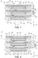
- Fig. 1 is a sectional view of a cell stack S comprising electrochemical cells 1 according to a first embodiment in a stacking direction.
- Fig. 2 is a sectional view of the cell stack S in the stacking direction corresponding to a II-II line in Fig. 1 .
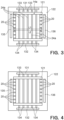
- Fig. 3 is a schematic view of the electrochemical cell 1 in the cell stack shown from a III-III line in Fig. 2 .
- the electrochemical cell 1 has a flat plate shape.
- a plurality of the electrochemical cells 1 are stacked one on another in their respective thickness directions.
- Figs. 1 to 3 show the electrochemical cells 1 and the cell stack S which are not operated and thus are at a room temperature (25°C).
- a direction in which the electrochemical cells 1 are stacked in the cell stack S is referred to hereunder as stacking direction Z.
- a direction orthogonal to the stacking direction Z, which extends in the right and left direction in Fig. 1 is referred to as X direction.
- a direction orthogonal to the stacking direction Z, which extends in the right and left direction in Fig. 2 is referred to as Y direction.
- the X direction and the Y direction are orthogonal to each other in a plane orthogonal to the stacking direction Z.
- a surface of a below-described constituent element of the electrochemical cell 1 or the cell stack S which is referred to as side surface, means a surface that is an outer surface of the constituent element, which faces the X direction and/or the Y direction. To see in a plan view used herebelow means a view seen in a direction parallel to the stacking direction Z.
- the electrochemical cell 1 comprises an electrode layered body 10, a separator 12, an anode side current collector 14a, a cathode side current collector 14c, a sealing plate 16, and a sealant member 18.
- the electrode layered body 10 is sometimes referred to simply as "cell”.
- the electrode layered body 10 includes an electrolyte 10e, a cathode 10c, an anode 10a, and an anode porous substrate 10g.
- the electrolyte 10e has a first surface 10e1 and a second surface 10e2 positioned opposite to the first surface 10e1.
- the cathode 10c is in contact with the first surface 10e1.
- the anode 10a is in contact with the second surface 10e2.
- the anode porous substrate 10g is in contact with a surface of the anode 10a, which surface is opposite to a surface in contact with the electrolyte 10e. Namely, in the electrode layered body 10, the anode porous substrate 10g, the anode 10a, the electrolyte 10e, and the cathode 10c are stacked in this order from below.
- the electrochemical cell 1 has a flat plate shape which is rectangular in a plan view.
- a shape in a plan view of the electrochemical cell 1 having a flat plate shape is not particularly limited, and may be circular, for example.
- the electrolyte 10e in this embodiment is a solid electrolyte and is made of a solid oxide with oxygen ion conductivity.
- the electrolyte 10e is formed from, for example, stabilized zirconia or a ceria-based solid solution, or a perovskite-type oxide, which are dense.
- the electrolyte 10e may be formed from zirconia that is stabilized with an oxide (Y 2 O 3 , Sc 2 O 3 , Yb 2 O 3 , Gd 2 O 3 , CaO, MgO, CeO 2 ) of at least one element selected from the group consisting of Y, Sc, Yb, Gd, Ca, Mg, and Ce.
- the electrolyte 10e may be formed from ceria doped with an oxide (Sm 2 O 3 , Gd 2 O 3 , Y 2 O 3 ) of at least one element selected from the group of Sm, Gd, and Y.
- the cathode 10c is porous and is formed from, for example, a perovskite-type oxide.
- the cathode 10c may be formed from, for example, LaSrMn oxide, LaSrCo oxide, LaSrCoFe oxide, LaSrFe oxide, etc.
- the anode 10a is porous and is formed from, for example, a sintered mixture (cermet) of metal and solid oxide.
- the anode 10a may be formed from, for example, Ni-YSZ (yttria stabilized zirconia), Ni-ScSZ (Scandia stabilized zirconia), etc.
- the fact that the electrolyte 10e is "dense" as described above means that the electrolyte 10e has a porosity that is at least lower than the cathode 10c and the anode 10a which are porous.
- the anode porous substrate 10g is also porous and is formed to have a sheet shape.
- the anode porous substrate 10g, the anode 10a, the electrolyte 10e, and the cathode 10c are stacked in this order from below and integrated.
- the anode porous substrate functions as a support that reinforces and supports the electrode layered body 10.
- the electrode layered body 10 may be formed by sequentially depositing, for example, on the anode porous substrate 10g, the anode 10a, the electrolyte 10e, and the cathode 10c. When the electrode layered body 10 is formed by these steps, the anode porous substrate 10g, the anode 10a, the electrolyte 10e, and the cathode 10c are automatically integrated. However, how to form the electrode layered body 10 is not particularly limited.
- the anode porous substrate 10g may be formed from a sintered body containing, e.g., metal particles and a metal oxide.
- the metal particles contained in the sintered body or solidly dissolved in the oxide may be one or more selected from the group consisting of, e.g., nickel (Ni), cobalt (Co), iron (Fe), and copper (Cu), or an alloy containing them.
- the electrochemical cell 1 is a sold oxide electrochemical cell, it may be formed from the aforementioned materials that are given by way of example.
- the type of the electrochemical cell 1 is not limited to a solid oxide.
- each part of the electrochemical cell may be formed from a corresponding material according to the type.
- the separator 12 comprises a base part 121 overlapped with the electrode layered body 10 in a direction in which the electrolyte 10e, the cathode 10c, and the anode 10a are stacked, i.e., in the stacking direction Z, and a frame body 122 surrounding a side surface of the electrode layered body 10.
- a cell housing 12a is formed inside the frame body 122.
- the electrode layered body 10 is installed in the cell housing 12a.
- the electrode layered body 10 is installed such that each side of the rectangle is along any of sides of the frame body 122, and that a gap is formed between the side surface of the electrode layered body 10 and the frame body 122. Namely, the electrode layered body 10 is surrounded by the frame body 122 such that the electrode layered body 10 is not in contact with an inner surface of the frame body 122, and that the gap is present between the electrode layered body 10 and the frame body 122.
- the base part 121 has a rectangular shape in a plan view.
- the frame body 122 has a rectangular frame shape in a plan view.
- the base part 121 is in contact with the anode side current collector 14a.
- the base part 121 is, through its another surface opposite to the surface in contact with the anode side current collector 14a, in contact with the cathode side current collector 14c of another electrochemical cell 1.
- the electrochemical cell 1 comprises a plurality of channels through which gases flow. Specifically, as shown in Figs. 1 to 3 , the electrochemical cell 1 comprises a fuel supply share channel 131, a fuel discharge share channel 132, a fuel supply branch channel 133, a fuel discharge branch channel 134, an oxygen supply share channel 135, an oxygen discharge share channel 136, an oxygen supply branch channel 137, and an oxygen discharge branch channel 138.
- the fuel supply share channel 131 is formed in one of two opposed side parts (upper and lower side parts in Fig. 3 ) of the frame body 122, and the fuel discharge share channel 132 is formed in the other side part of the two side parts.
- the oxygen supply share channel 135 is formed one of two opposed other side parts (right and left side parts in Fig. 3 ) of the fame body 122, and the oxygen discharge share channel 136 is formed in the other side part of the two side parts.
- the fuel supply share channel 131, the fuel discharge share channel 132, the oxygen supply share channel 135, and the oxygen discharge share channel 136 respectively pass through the frame body 122 in the stacking direction. As shown in Figs. 1 and 2 , the fuel supply share channel 131, the fuel discharge share channel 132, the oxygen supply share channel 135, and the oxygen discharge share channel 136 are fluidically connected respectively to the corresponding fuel supply share channel 131, the fuel discharge share channel 132, the oxygen supply share channel 135, and the oxygen discharge share channel 136 of another electrochemical cell 1.
- the fuel supply branch channel 133 is formed adjacent to the fuel supply share channel 131 in the frame body 122.
- the fuel supply branch channel 133 is formed in the side part of the frame body 122, in which the fuel supply share channel 131 is formed, to fluidically connect the fuel supply share channel 131 and the cell housing 12a.
- the fuel discharge branch channel 132 is formed adjacent to the fuel discharge share channel 132 in the frame body 122.
- the fuel discharge branch channel 134 is formed in the side part of the frame body 122, in which the fuel discharge share channel 132 is formed, to fluidically connect fuel discharge share channel 132 and the cell housing 12a.
- a fuel gas flowing through the fuel supply share channel 131 can flow from the fuel supply branch channel 133 into the cell housing 12a.
- the fuel gas can be supplied to the anode 10a in the electrode layered body 10.
- the fuel gas having passed through the electrode layered body 10 can flow from the cell housing 12a to the fuel discharge share channel 132 through the fuel discharge branch channel 134. This allows an unreacted fuel gas to be discharged from the fuel discharge share channel 132.
- the fuel supply branch channel 133 and the fuel discharge branch channel 134 are formed in this embodiment as grooves that are recessed from a top surface of the frame body 122 and extend in a direction crossing the stacking direction.
- the fuel supply branch channel 133 and the fuel discharge branch channel 134 may be holes passing through the frame body 122.
- the oxygen supply branch channel 137 and the oxygen discharge branch channel 138 are provided in the sealing plate 16. Details on this will be described later.
- the separator 12 at least partially forms the channel of a fuel gas to be supplied to the anode 10a and the channel of oxygen to be supplied to the cathode 10c.
- the separator 12 is formed from an electrically conductive material that is dense enough not to allow a fuel gas and oxygen to transmit therethrough.
- the separator 12 is formed from, e.g., metal or ceramics.
- a linear expansion coefficient of the material of the separator 12 is preferably close to a linear expansion coefficient of the electrode layered body 10.
- the fact that the separator 12 is "dense" as described above means that the separator 12 has a porosity that is at least lower than the cathode 10c and the anode 10a which are porous.
- the frame body 122 is a part of separator 12 and the frame body 122 is upstanding and is integrated with an outer circumferential portion of the base part 121.
- the frame body 122 and the base part 121 may be separately formed and connected to each other thereafter.
- the anode side current collector 14a is located to be in contact with the anode porous substrate 10g and the base part 121 of the separator 12.
- the cathode side current collector 14c is located to be in contact with the cathode 10c and the separator 12 of another electrochemical cell 1.
- the anode side current collector 14a may be adhered to the anode porous substrate 10g and the base part 121 of the separator 12 through an adhesive.
- the cathode side current collector 14c may be adhered to the cathode 10c and the separator 12 of another electrochemical cell 1 through an adhesive.
- the anode side current collector 14a and the cathode side current collector 14c are electrically conductive sheet-shaped members, and are formed from an electrically conductive material.
- the anode side current collector 14a and the cathode side current collector 14c may be formed from, for example, stainless steel, iron, nickel, titanium, aluminum, Ag, Pt, Au, or an alloy material including one or more of them.
- the anode side current collector 14a and the cathode side current collector 14c may be formed from a gas-diffusive structure. More specifically, the anode side current collector 14a and the cathode side current collector 14c may be formed from a metal mesh, an expanded metal, or a metal foam, which has gas diffusivity and relatively easily deformable.
- Materials of these mesh, expanded metal and metal foam may be, for example, stainless steel, iron, nickel, titanium, aluminum, Ag, Pt, Au, or an alloy material including one or more of them, similarly to the above.
- the gas diffusivity is a property that diffuses and transmits a gas flowing thereinto.
- the anode side current collector 14a is provided with a fuel gas channel 24a.
- the cathode side current collector 14c is provided with an oxygen channel 24c.
- the fuel gas channel 24a and the oxygen channel 24c extend orthogonally to each other when seen in the stacking direction Z.
- the patterns of the fuel gas channel 24a and the oxygen channel 24c are not particularly limited.
- the anode side current collector 14a is formed to have a corrugated plate shape in which concavities and convexities are repeated.
- the fuel gas channel 24a is formed between the adjacent convexities of the anode side current collector 14a, which are upwardly convex in Fig. 2 , to extend in the X direction. As shown in Figs. 1 and 2 , one end of the fuel gas channel 24a in the X direction is fluidically connected to the fuel supply share channel 131 through the cell housing 12a and the fuel supply branch channel 133. The other end of the fuel gas channel 24a in the X direction is fluidically connected to the the fuel discharge share channel 132 through the cell housing 12a and the fuel discharge branch channel 134.
- the cathode side current collector 13c is formed to have a corrugated plate shape in which concavities and convexities are repeated.
- the oxygen channel 24c is formed between the adjacent concavities of the anode side current collector 14c, which are downwardly concave in Fig. 1 , to extend in the Y direction. As shown in Figs. 1 and 2 , one end of the oxygen channel 24c in the Y direction is fluidically connected to the oxygen supply share channel 135 through the oxygen supply branch channel 137. The other end of the oxygen channel 24c in the Y direction is fluidically connected to the oxygen discharge share channel 136 through the oxygen discharge branch channel 138.
- the anode side current collector 14a and the cathode side current collector 14c may not be provided with the aforementioned fuel gas channel 24a and the oxygen channel 24c.
- the anode side current collector 14a and the cathode side current collector 14c is formed from a porous material, and the separator 12 may have groove-shaped channels formed therein, which are similar to the fuel gas channel 24a and the oxygen channel 24c.
- a size of the cathode 10c is smaller than that of the electrolyte 10e in a plan view, so that an outer circumferential portion of the electrolyte 10e is not covered with the cathode 10c.
- the sealing plate 16 is installed in straddling a surface of the electrolyte 10e in which the cathode 10c is not positioned, and the top surface of the frame body 122.
- the sealing plate 16 is a rectangular frame-shaped plate member which surrounds the cathode 10c and the cathode side current collector 14c. Oxygen to be supplied to the cathode 10c can flow into an inside space of the sealing plate 16.
- the sealing plate 16 separates the inside space of sealing plate 16 and a gas atmosphere of the cell housing 12a.
- the oxygen supply branch channel 137 and the oxygen discharge branch channel 138 are formed in the sealing plate 16.
- the oxygen supply branch channel 137 is formed to fluidically connect the oxygen supply share channel 135 and the inside space of sealing plate 16.
- the oxygen discharge branch channel 138 is formed to fluidically connect the oxygen discharge share channel 136 and the inside space of sealing plate 16.
- the sealing plate 16 is formed from a dense material such as metal or ceramics. The sealing plate 16 may be formed from the same material as the separator 12.
- the sealant member 18 is provided between the sealing plate 16 and the separator 12 of another electrochemical cell 1 to air-tightly and liquid-tightly seal a space between the sealing plate 16 and the separator 12 of another electrochemical cell 1.
- the sealant member 18 may be formed from a compressive material that deforms when pressurized.
- the electrochemical cell 1 constitutes a single unit, so-called single cell by the aforementioned electrode layered body 10, the separator 12, the anode side current collector 14a, the cathode side current collector 14c, the sealing plate 16, and the sealant member 18.
- the cell stack S is formed by stacking such electrochemical cells 1 the number of which is optional. End plates (illustration omitted) or the like are located on both ends of the cell stack S in the stacking direction Z. The pair of end plates or the like are fastened and secured by fastening means, such as a plurality of bolts and nuts (illustration omitted).
- the electrochemical cell 1 comprises a gas-flow suppression part[s] 20.
- the gas-flow suppression part 20 is positioned at least partially adjacent to the side surface of the electrode layered body 10.
- the gas-flow suppression part 20 according to this embodiment is positioned partially adjacent to side surface of a part consisting of the anode porous substrate 10g, the anode 10a, the electrolyte 10e of the electrode layered body 10, but is not adjacent to the cathode 10c.
- the gap is formed between the side surface of the electrode layered body 10 and the frame body 122.
- the gas-flow suppression part 20 is positioned in the gap between the side surface of the electrode layered body 10 and the frame body 12 in order to block the flow of fuel gas that is going to flow through the gap between the side surface of the electrode layered body 10 and the fame body 122.
- the gas-flow suppression part 20 is formed from a material different from those of the electrolyte 10e, the cathode 10c, and the anode 10a.
- the gas-flow suppression part 20 is formed from a material having a linear expansion coefficient greater than linear expansion coefficients of the electrolyte 10e, the cathode 10c, and the anode 10a.
- the electrolyte 10e, the cathode 10c, and the anode 10a are mainly formed from ceramics.
- the gas-flow suppression part 20 may be formed from, for example, stainless steel, iron, nickel, titanium, aluminum, Ag, Pt, Au, or an alloy material including one or more of them. This allows the linear expansion coefficient of the gas-flow suppression part 20 to be greater than the linear expansion coefficients of the electrolyte 10e, the cathode 10c, and the anode 10a.
- the gas-flow suppression part 20 is formed integrally with the anode side current corrector 14a formed from metal in this embodiment.
- the anode side current side current collector 14a comprises the gas-flow suppression part 20 positioned at least partially adjacent to the side surface of the electrode layered body 10.
- the gas-flow suppression part 20 is integrated with the electrode layered body 10.
- the gas-flow suppression part 20 may not be integrated with the anode side current collector 14a, but may be integrated with the anode porous substrate 10g.
- the gas-flow suppression part 20 is formed from a material similar to that of the anode side current collector 14a.
- the gas-flow suppression part 20 may be formed from a gas-diffusive structure. More specifically, the gas-flow suppression part 20 may be formed from a metal mesh, an expanded metal, or a metal foam, which is gas diffusive and relatively easily deformable.
- the gas-flow suppression part 20 is positioned apart from the frame body 122 when the electrochemical cell 1 is not operated and thus is at a room temperature (25°C), for example.
- the linear expansion coefficient of the gas-flow suppression part 20 is greater than the linear expansion coefficients of the electrolyte 10e, the cathode 10c, and the anode 10a, the gas-flow suppression part 20 can easily expand toward the frame body 122 such that a distance between the gas-flow suppression part 20 and the fame body 122 decreases, during operation of the electrochemical cell 1. This makes it easier to block the flow of fuel gas flowing through the gap between the electrode layered body 10 and the fame body 122.
- a member such as the gas-flow suppression part 20 which blocks the flow of fuel gas as described above, from the same material as that of the electrode layered body 10 mainly made of ceramics.
- a member such as the gas-flow suppression part 20 which blocks the flow of fuel gas as described above, from the same material as that of the electrode layered body 10 mainly made of ceramics.
- to form the gas-flow suppression part 20 from a material different from those of the electrolyte 10e, the cathode 10c, and the anode 10a may be advantageous in terms of machining of the gas-flow suppression part 20.
- the gas-flow suppression part 20 in this embodiment has a convex shape projecting from the electrode layered body 10 toward the fame body 122.
- the gas-flow suppression part 20 is formed as a rectangular plate having a constant thickness, with its plate plane being along the stacking direction Z.
- a plurality of the gas-flow suppression parts 20 are provided at intervals therebetween along a direction surrounding the side surface of the electrode layered body 10.
- the gas-flow suppression parts 20 are provided at intervals therebetween along parts of the side surface of the electrode layered body 10, which are parallel to the fuel gas channel 24 of the anode current collector 14a.
- the adjacent gas-flow suppression parts 20 are preferably apart from each other by some distance, in order that a fuel gas flowing into therebetween to rapidly contract and expand so as to generate pressure loss.
- the gas-flow suppression parts 20 are preferably configured such that, when a flow gas flows into a space between the adjacent gas-flow suppression parts 20, a vortex is generated.
- this embodiment intends that the gas-flow suppression part 20 expands toward the frame body 122 such that the distance between the gas-flow suppression part 20 and the frame body 122 decreases, when the electrochemical cell 1 is operated.
- the gas-flow suppression part 20 is configured to come into contact with or come close to the frame body 122 by thermal expansion, when reaching or exceeding a predetermined temperature.
- the gas-flow suppression part 20 is positioned in the gap between the electrode layered body 10 and the frame body 122 in such a manner that the gas-flow suppression part 20 is apart from the frame body 122, when the electrochemical cell 1 is not operated and thus is at a room temperature (25°C), in other words, when it is assembled.
- the linear expansion coefficient of the gas-flow suppression part 20 is set such that it is greater than the linear expansion coefficients of the electrolyte 10e, the cathode 10c, and the anode 10a, and is also greater than a linear expansion coefficient of the frame body 122.
- the linear expansion coefficient of the gas-flow suppression part 20 and the linear expansion coefficient of the frame body 122 are set such that a difference between a dimension of the expanded gas-flow suppression part 20 at a predetermined temperature and a dimension of the expanded frame body 122 at the predetermined temperature is equal to or greater than a distance between the gas-flow suppression part 20 and the frame body 122 at a room temperature. As shown in Fig. 4 , this allows the gas-flow suppression part 20 to be in contact with the frame body 122 by thermal expansion, when reaching or exceeding the predetermined temperature.
- a reference numeral L1 in Fig. 3 indicates a distance between opposed inner surfaces of the frame body 122.
- a reference numeral L2 indicates a distance between distal ends of the gas-flow suppression parts 20 provided on the opposed edges of the anode current collector 14a.
- a distance between the gas-flow suppression part 10 and the frame body 122 at a room temperature is calculated by ((L1-L2)/2).
- the linear expansion coefficient of the gas-flow suppression part 20 and the linear expansion coefficient of the frame body 122 are set such that the following relationship holds: L 1 ⁇ L 2 / 2 ⁇ c 1 ⁇ L 1 ⁇ c 2 ⁇ L 2 ⁇ Td ⁇ Ts ⁇ 0 wherein c1 represents the linear expansion coefficient of the frame body 122, c2 represents the linear expansion coefficient of the gas-flow suppression part 20, Td represents the predetermined temperature, and Ts represents the room temperature.
- the gas-flow suppression part 20 is thermally expanded to come into contact with the frame body 122.
- the gas-flow suppression part 20 is preferably configured to be deformed or easily buckled so as not to constrain deformation of the electrode layered body 10 or not to transmit load to the electrode layered body 10, even when the gas-flow suppression part 20 comes into contact with the frame body 122 at a high-temperature operation state.
- the gas-flow suppression part 20 is preferably formed from a structure such as a metal mesh, an expanded metal, or a metal foam, which is gas diffusive and relatively easily deformable.
- a nickel foam is particularly preferred.
- the gas-flow suppression part 20 is apart from the frame body 122 when the electrochemical cell 1 is not operated and thus is at a room temperature (25°C), in other words, when it is assembled, the gas-flow suppression part 20 does not interfere with the assembly of the frame body 122 and the electrode layered body 10.
- the top surface of the gas-flow suppression part 20 (surface facing sealing plate 16) is also positioned apart from the sealing plate 16 when the electrochemical cell 1 is not operated and thus is at a room temperature (25°C).
- the top surface of the gas-flow suppression part 20 is preferably formed apart from the sealing plate 16, in other words, formed not to exceed the electrolyte 10e, in order to avoid affecting proper assembly.
- the gas-flow suppression part 20 can come close to the sealing plate 16 by thermal expansion at a high temperature. This can suitably suppress the fuel gas from flowing.
- the fuel gas for the SOEC may be a gas containing at least water vapor or carbon dioxide.
- the fuel gas flows from the fuel supply branch cannel 133 into the cell housing 12a.
- the fuel gas passes through the fuel gas channel 24a of the anode side current collector 14a, and is diffused here by the anode porous substrate 10g.
- the fuel gas is supplied to the anode 10a of the electrode layered body 10.
- the fuel gas is used as a reactant for an electrolysis reaction in the electrode layered body 10.
- the fuel gas, which was not used as a reactant for the electrolysis reaction is discharged outside through the fuel supply branch channel 133 and the fuel discharge branch channel 134.
- the gas-flow suppression part 20 can suppress the fuel gas from flowing through the gap.
- the gas-flow suppression part 20 thermally expands toward the frame body 122 such that the gap between the gas-flow suppression part 20 and the frame body 122 decreases, so that the gas-flow suppression part 20 comes into contact with or comes close to the frame body 122. This can improve seal performance.
- the electrolyte 10e is a solid oxide, it is difficult to tightly contact the electrode layered body 10 and the frame body 122, whereby a gap is formed between the electrode layered body 10 and the frame body 122.
- the gas-flow suppression part 20, which is produced by a material different from that of the electrode layered body 10 in this embodiment, can easily provide a desired seal function.
- the gas-flow suppression part 20 is produced from, e.g., a metal with improved processability, it is easy to produce the gas-flow suppression part 20 having a size or a dimension that does not allow contact with the frame body 122 can be easily produced, or the gas-flow suppression part 20 which does not cause unwanted deformation or internal stress in the electrode layered body 10 even when it comes into contact with the frame body 122. This can effectively provide seal performance.
- the gas-flow suppression part 20 can effectively provide seal performance, similarly to the above.
- the electrochemical cell 1 comprises the electrode layered body 10 including the electrolyte 10e having the first surface 10e1 and the second surface 10e2 positioned opposite to the first surface 10e1, the cathode in contact with the first surface 10e1, and the anode 10a in contact with the second surface 10e2; and the gas-flow suppression part 20 that is positioned at least partially adjacent to a side surface of the electrode layered body 10, and is formed from a material different from those of the electrolyte 10e, the cathode 10c, and the anode 10a.
- the electrochemical cell 1 can suppress the fuel gas from flowing through the gap by means of the gas-flow suppression part 20.
- the gas-flow suppression part 20 is produced from a material different from that of the electrode layered body 10, e.g., a metal with improved processability.
- the electrochemical cell 1 can suppress the gas from flowing through between the electrode layered body 10 and the frame body 122 surrounding the same, while suppressing unwanted internal stress and deformation of the electrochemical cell 1 caused by contact between the electrode layered body 10 and the frame body 122 surrounding the same.
- a frame body 122 in this embodiment has a plurality of convexities 30 projecting toward an electrode layered body 10.
- Each convexity 30 projects toward parts of a side surface of the electrode layered body 10, in which gas-flow suppression parts 20 are adjacent.
- the convexity 30 is formed such that its distal end is apart from the side surface of the electrode layered body 10.
- the convexity 30 is formed as a rectangular plate having a constant thickness, with its plate plane being along a stacking direction Z.
- the gas-flow suppression parts 20 and the convexities 30 are alternated.
- the convexity 30 is positioned to block a fuel gas passing through between the distal end of the gas-flow suppression part 20 and the frame body 122.
- the convexity 30 has a function of preventing a gas from blowing therethrough. Since the gas-flow suppression parts 20 and the convexities 30 are alternated, the fuel gas passing through the distal end of the gas-flow suppression part 20 and the frame body 122 may repeat rapid contraction and rapid expansion in succeeding spaces between the adjacent gas-flow suppression parts 20 and the convexities 30 to generate pressure loss. This can effectively suppress the fuel gas from flowing through the gap between the gas-flow suppression parts 20 and the frame body 122.
- the space between the adjacent gas-flow suppression part 20 and the convexity 30 is preferably configured to generate a vortex when the fuel gas flows thereinto.
- the gas-flow suppression part 20 which is apart from the frame body 122 at a room temperature, is configured to come into contact with or come close to the frame body 122 by thermal expansion, when reaching or exceeding a predetermined temperature.
- the convexity 30 can block the flow of fuel gas. This can improve seal performance.
- a gas-flow suppression part 20 covers a side surface of an electrode layered body 10 over a wide range.
- the gas-flow suppression part 20 is formed to have a wall shape extending in a direction surrounding the side surface of the electrode layered body 10.
- the gas-flow suppression part 20 is formed to partially or entirely cover a part of the side surface of the electrode layered body 10, which extends from a fuel supply share channel 131 toward a fuel discharge share channel 132.
- the gas-flow suppression part 20 is positioned apart from the frame body 122 when the electrochemical cell 1 is not operated and thus is at a room temperature (25°C), for example, and is also maintained to be apart from the frame body 122 when the electrochemical 3 is operated.
- the gas-flow suppression part 20 in this embodiment may be configured to come into contact with or come close to the frame body 122 by thermal expansion, when reaching or exceeding a predetermined temperature.
- This embodiment can also suppress a fuel gas from flowing through a gap between the electrode layered body 10 and the frame body 122.
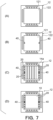
- Fig. 7 shows a manufacturing procedure of the electrochemical cell 1 according to the first embodiment
- the electrochemical cells according to the second and third embodiments can also be manufactured by the similar procedure.
- an assembly jig 40 is used for forming a desired gap between the electrode layered body 10, in particular, the gas-flow suppression part 20, and the frame body 122.
- the assembly jig 40 may be, for example, a rectangular block formed to have a dimension slightly smaller than the desired gap between the electrode layered body 10 and the frame body 122.
- the separator 12 is prepared first. Thereafter, as shown in Fig. 7(B) , the assembly jig 40 is installed on the base part 121 of the separator 12. At this time, at least two assembly jigs 40 are located such that they are close to the respective two opposed sides of the frame body 122.
- the aforementioned two sides of the frame body 122 are sides that are respectively opposed to the gas-flow suppression parts 20, after assembly.
- the anode side current collector 14a is placed on the base part 121 so as not to come into contact with the assembly jigs 40. Under this state, the anode side current collector 14a is adhered to the base part 121 by an adhesive or the like. Thus, the anode side current collector 14a is secured at a predetermined position, and a desired distance between the gas-flow suppression part 20 integral with the anode side current collector 14a and the frame body 122 is obtained.
- the electrode layered body 10 is placed on the anode side current collector 14a so as not to come into contact with the assembly jigs 40 and the gas-flow suppression parts 20. Under this state, the electrode layered body 10 is adhered to the anode side current collector 14a by an adhesive or the like. Thus, the electrode layered body 10 is secured at a predetermined position, and a desired gap between the electrode layered body 10 and the frame body 122 is obtained. This allows the gas-flow suppressions 20 to properly function. After that, the assembly jigs 40 are puled out for removal.
- the gas-flow suppression part 20 in the above first and second embodiments has a plate-like shape having a constant thickness, but the gas-flow suppression part 20 may be tapered toward the frame body 122. Alternatively, the gas-flow suppression part 20 may have a block shape.
- the gas-flow suppression part 20 in the above first to third embodiments is configured to suppress flow of fuel gas
- the gas-flow suppression part 20 may be used to suppress flow of oxygen.
- the gas-flow suppression part 20 is located between the cathode 10c and the sealing plate 16.
- the gas-flow suppression part 20 may be integrated with the cathode side current collector 14.
Landscapes
- Chemical & Material Sciences (AREA)
- Engineering & Computer Science (AREA)
- Chemical Kinetics & Catalysis (AREA)
- Electrochemistry (AREA)
- Manufacturing & Machinery (AREA)
- Sustainable Development (AREA)
- Life Sciences & Earth Sciences (AREA)
- Sustainable Energy (AREA)
- General Chemical & Material Sciences (AREA)
- Organic Chemistry (AREA)
- Metallurgy (AREA)
- Materials Engineering (AREA)
- Fuel Cell (AREA)
- Electrolytic Production Of Non-Metals, Compounds, Apparatuses Therefor (AREA)
- Inert Electrodes (AREA)
Abstract
Description
- The embodiments described herein relate to an electrochemical cell, a current collector, and a cell stack.
- This application is based upon and claims the benefit of priority from the prior
Japanese Patent Application No. 2023-43298 filed on March 17, 2023 - There are various types of electrochemical cells, such as a sold polymer type, a solid oxide type, etc. Since a solid oxide electrochemical cell uses a solid oxide as an electrolyte, its operation temperature is high (e.g., 600 to 1000 °C). Due to an operation at such a high operation temperature, the sold oxide electrochemical cell provides a high reaction rate without the use of expensive noble metal catalyst.
- The above high reaction rate enables high power generation efficiency when the solid oxide electrochemical cell is operated as a fuel cell (solid oxide fuel cell: SOFC). When the solid oxide electrochemical cell is operated as an electrolytic cell (solid oxide electrolytic cell: SOEC), hydrogen, for example, can be manufactured efficiently at a low electrolytic voltage. Thus, the solid oxide electrochemical cell has attracted attention as a technology for realizing a highly efficient fuel cell, an electrolytic cell for manufacturing hydrogen, a power storage system combining them, etc.
- The electrochemical cell comprises a layered body (hereinafter sometimes referred to as electrode layered body) including at least an air electrode, an electrolyte, and a fuel electrode. The air electrode, the electrolyte, and the fuel electrode are generally formed from materials having different properties from each other. The air electrode and the fuel electrode are electrical conductors and are generally formed from porous materials. Different gases are supplied respectively to the air electrode and the fuel electrode, with the electrolyte therebetween. On the other hand, the electrolyte is an ion conductor.
- Electrochemical cell shapes may be a flat plate shape, a cylindrical shape, a cylindrical-plate shape, etc. For example, in an electrochemical cell having a flat plate shape, the air electrode, the electrolyte, the fuel electrode, etc. are stacked like flat plates.
- A structure that integrates a plurality of electrochemical cells in order to generate a large amount of power or hydrogen is generally referred to as cell stack. For example, in a cell stack including a plurality of electrochemical cells having a flat plate shape, the electrochemical cells are stacked in their respective thickness directions. Corresponding gases are supplied to the air electrode and the fuel electrode of each electrochemical cell. The respective electrochemical cells are electrically connected in series. The electrochemical cell constituting the cell stack generally comprises a separator. In the cell stack, an electrochemical cell is stacked on another electrochemical cell such that its separator and the other electrochemical cell are in contact with each other. In such a structure, gas channels of the respective electrochemical cells are separated by the separator. The separator is electrically conductive, and thus conducts electricity to other electrochemical cells.
- The aforementioned separator may delimit a gas channel for any of the air electrode and the fuel electrode, by, for example, a plate-shaped base part in contact with the electrode layered body in a stacking direction (thickness direction) of the electrochemical cell, and a frame body surrounding a circumference of the electrode layered body. In the separator having such a structure, the frame body may have a gas supply channel and a gas discharge channel. In this case, a gas having flown into the frame body from the supply channel is supplied to the air electrode or the fuel electrode in the electrochemical cell, and the gas having passed through the air electrode or the fuel electrode is discharged outside from the discharge channel.
- For example, a gas utilization rate is used as an indicator for evaluating performance of the cell stack as described above. In an electrolysis mode where hydrogen is generated, an amount of hydrogen produced per unit of electric power is important.
- Some of the gas supplied to the electrochemical cell may be discharged without passing through a reaction zone (air electrode / fuel electrode in electrode layered body) of the electrochemical cell. Specifically, there may be a gas that flows bypassing the reaction zone, and/or a gas that leaks from the reaction zone to the outside thereof.
- However, the gas flow that does not pass through the reaction zone does not contribute to the reaction. Thus, it is desirable to ensure gas sealability to prevent a gas from bypassing the reaction zone and a gas from leaking from the reaction zone. It is also desirable that the suitable gas sealability allows the gas to flow such that reactions at the air electrode and the fuel electrode can be carried out efficiently.
- As described above, when the frame body surrounding the circumference of the electrode layered body is provided, a gap may be formed between ethe electrode layered body and the frame body. In this case, there may be a gas that is going to bypass the reaction zone through this gap. The flow of gas through the gap can be suppressed by tightly contacting the electrode layered body and the frame body to each other. However, it is sometimes difficult to tightly contact the electrode layered body and the frame body property, because of variations in dimensional processing accuracy of the electrode layered body and the frame body. In addition, the electrode layered body and the frame body may expand to mutually interfere with each other when a temperature rises, which applies pressure to a contact surface between the electrode layered body and the frame body during operation at a high temperature. In this case, unwanted internal stress and/or deformation may occur in the electrochemical cell. If the pressure on the contact surface becomes excessively large, the electrochemical cell may be damaged, so that power generation performance or electrolysis performance may be severely impaired.
- In view of the above circumstances, it is sometimes necessary to provide a gap between the electrode layered body and the fame body in the electrochemical cell. Particularly when a solid oxide electrochemical cell is used, mutual interference upon expansion is often a problem because of its high operation temperature. In addition, dimensional processing accuracy of the electrochemical cell (electrode layered body and frame body) may be likely to vary because of materials to be used. Thus, in the solid oxide electrochemical cell, a gap is usually intentionally formed between the electrode layered body and the frame body. However, if the gap between the electrode layered body and the fame body is excessively large, increase in gas that does not pass through the oxygen electrode or the fuel electrode may decrease a gas utilization rate, causing decrease in power generation performance or electrolysis performance. If the gas supplied to the reaction zone is significantly short of a desired supply, the electrochemical cell may be damaged.
- In consideration of the above, an object of an embodiment described below is to provide an electrochemical cell, a current collector, and a cell stack that are capable of reducing unwanted internal stress and/or deformation in the electrochemical cell, which is caused by contact between an electrode layered body including an oxygen electrode, an electrolyte and a fuel electrode, and a member therearound, and also suppressing a gas from passing through a gap between the electrode layered body and the member therearound.
-
-
Fig. 1 is a sectional view of a cell stack comprising electrochemical cells according to a first embodiment in a staking direction. -
Fig. 2 is a sectional view of the cell stack in the stacking direction corresponding to a II-II line inFig. 1 . -
Fig. 3 is a schematic view of the electrochemical cell in the cell stack shown from a III-III line inFig. 2 . -
Fig. 4 is a view showing that the electrochemical cell shown inFig. 1 thermally expands during operation. -
Fig. 5 is a view schematically showing an electrochemical cell according to a second embodiment. -
Fig. 6 is a view schematically showing an electrochemical cell according to a third embodiment. -
Figs. 7(A) to 7(D) are view for describing an example of a manufacturing method of the electrochemical cell according to an embodiment. - In one embodiment, an electrochemical cell comprises: an electrode layered body including an electrolyte having a first surface and a second surface positioned opposite to the first surface, a cathode in contact with the first surface, and an anode in contact with the second surface; and a gas-flow suppression part positioned at least partially adjacent to a side surface of the electrode layered body, (for example, the side surface may be positioned between the first surface and the second surface) wherein the gas-flow suppression part is formed from a material different from those of the electrolyte, the cathode, and the anode.
- In one embodiment, a current collector positioned in contact with a cathode or an anode of an electrode layered body of an electrochemical cell in a direction in which an electrolyte, the cathode and the anode of the electrode layered body are stacked, wherein the current collector comprises a gas-flow suppression part positioned at least partially adjacent to a side surface of the electrode layered body.
- In one embodiment, a cell stack comprises a plurality of the stacked electrochemical cells.
- Respective embodiments are described hereunder with reference to the attached drawings. In the drawings attached to this specification, a scale dimension, an aspect ratio and so on are sometimes changed and exaggerated from the actual ones, for the convenience of easiness in illustration and understanding.
-
Fig. 1 is a sectional view of a cell stack S comprisingelectrochemical cells 1 according to a first embodiment in a stacking direction.Fig. 2 is a sectional view of the cell stack S in the stacking direction corresponding to a II-II line inFig. 1 .Fig. 3 is a schematic view of theelectrochemical cell 1 in the cell stack shown from a III-III line inFig. 2 . Theelectrochemical cell 1 has a flat plate shape. In the cell stack 3, a plurality of theelectrochemical cells 1 are stacked one on another in their respective thickness directions.Figs. 1 to 3 show theelectrochemical cells 1 and the cell stack S which are not operated and thus are at a room temperature (25°C). - A direction in which the
electrochemical cells 1 are stacked in the cell stack S is referred to hereunder as stacking direction Z. A direction orthogonal to the stacking direction Z, which extends in the right and left direction inFig. 1 , is referred to as X direction. A direction orthogonal to the stacking direction Z, which extends in the right and left direction inFig. 2 , is referred to as Y direction. The X direction and the Y direction are orthogonal to each other in a plane orthogonal to the stacking direction Z. - A surface of a below-described constituent element of the
electrochemical cell 1 or the cell stack S, which is referred to as side surface, means a surface that is an outer surface of the constituent element, which faces the X direction and/or the Y direction. To see in a plan view used herebelow means a view seen in a direction parallel to the stacking direction Z. - As shown in
Figs. 1 and 2 , theelectrochemical cell 1 comprises an electrode layeredbody 10, aseparator 12, an anode sidecurrent collector 14a, a cathode sidecurrent collector 14c, a sealingplate 16, and asealant member 18. The electrode layeredbody 10 is sometimes referred to simply as "cell". - The electrode layered
body 10 includes anelectrolyte 10e, acathode 10c, ananode 10a, and an anodeporous substrate 10g. Theelectrolyte 10e has a first surface 10e1 and a second surface 10e2 positioned opposite to the first surface 10e1. - The
cathode 10c is in contact with the first surface 10e1. Theanode 10a is in contact with the second surface 10e2. The anodeporous substrate 10g is in contact with a surface of theanode 10a, which surface is opposite to a surface in contact with theelectrolyte 10e. Namely, in the electrode layeredbody 10, the anodeporous substrate 10g, theanode 10a, theelectrolyte 10e, and thecathode 10c are stacked in this order from below. - In detail, the
electrochemical cell 1 has a flat plate shape which is rectangular in a plan view. However, a shape in a plan view of theelectrochemical cell 1 having a flat plate shape is not particularly limited, and may be circular, for example. - The
electrolyte 10e in this embodiment is a solid electrolyte and is made of a solid oxide with oxygen ion conductivity. In this case, theelectrolyte 10e is formed from, for example, stabilized zirconia or a ceria-based solid solution, or a perovskite-type oxide, which are dense. Theelectrolyte 10e may be formed from zirconia that is stabilized with an oxide (Y2O3, Sc2O3, Yb2O3, Gd2O3, CaO, MgO, CeO2) of at least one element selected from the group consisting of Y, Sc, Yb, Gd, Ca, Mg, and Ce. Alternatively, theelectrolyte 10e may be formed from ceria doped with an oxide (Sm2O3, Gd2O3, Y2 O3) of at least one element selected from the group of Sm, Gd, and Y. - The
cathode 10c is porous and is formed from, for example, a perovskite-type oxide. In detail, thecathode 10c may be formed from, for example, LaSrMn oxide, LaSrCo oxide, LaSrCoFe oxide, LaSrFe oxide, etc. - The
anode 10a is porous and is formed from, for example, a sintered mixture (cermet) of metal and solid oxide. In detail, theanode 10a may be formed from, for example, Ni-YSZ (yttria stabilized zirconia), Ni-ScSZ (Scandia stabilized zirconia), etc. The fact that theelectrolyte 10e is "dense" as described above means that theelectrolyte 10e has a porosity that is at least lower than thecathode 10c and theanode 10a which are porous. - The anode
porous substrate 10g is also porous and is formed to have a sheet shape. In this embodiment, the anodeporous substrate 10g, theanode 10a, theelectrolyte 10e, and thecathode 10c are stacked in this order from below and integrated. In this embodiment, the anode porous substrate functions as a support that reinforces and supports the electrode layeredbody 10. - The electrode layered
body 10 may be formed by sequentially depositing, for example, on the anodeporous substrate 10g, theanode 10a, theelectrolyte 10e, and thecathode 10c. When the electrode layeredbody 10 is formed by these steps, the anodeporous substrate 10g, theanode 10a, theelectrolyte 10e, and thecathode 10c are automatically integrated. However, how to form the electrode layeredbody 10 is not particularly limited. - The anode
porous substrate 10g may be formed from a sintered body containing, e.g., metal particles and a metal oxide. The metal particles contained in the sintered body or solidly dissolved in the oxide may be one or more selected from the group consisting of, e.g., nickel (Ni), cobalt (Co), iron (Fe), and copper (Cu), or an alloy containing them. - Since the
electrochemical cell 1 according to this embodiment is a sold oxide electrochemical cell, it may be formed from the aforementioned materials that are given by way of example. However, the type of theelectrochemical cell 1 is not limited to a solid oxide. When theelectrochemical cell 1 is a sold polymer electrochemical cell or a molten carbonate electrochemical cell, each part of the electrochemical cell may be formed from a corresponding material according to the type. - The
separator 12 comprises abase part 121 overlapped with the electrode layeredbody 10 in a direction in which theelectrolyte 10e, thecathode 10c, and theanode 10a are stacked, i.e., in the stacking direction Z, and aframe body 122 surrounding a side surface of the electrode layeredbody 10. In this embodiment, acell housing 12a is formed inside theframe body 122. The electrode layeredbody 10 is installed in thecell housing 12a. The electrode layeredbody 10 is installed such that each side of the rectangle is along any of sides of theframe body 122, and that a gap is formed between the side surface of the electrode layeredbody 10 and theframe body 122. Namely, the electrode layeredbody 10 is surrounded by theframe body 122 such that the electrode layeredbody 10 is not in contact with an inner surface of theframe body 122, and that the gap is present between the electrode layeredbody 10 and theframe body 122. - As shown in
Fig. 3 , thebase part 121 has a rectangular shape in a plan view. Theframe body 122 has a rectangular frame shape in a plan view. As shown inFigs. 1 and 2 , thebase part 121 is in contact with the anode sidecurrent collector 14a. Thebase part 121 is, through its another surface opposite to the surface in contact with the anode sidecurrent collector 14a, in contact with the cathode sidecurrent collector 14c of anotherelectrochemical cell 1. - The
electrochemical cell 1 comprises a plurality of channels through which gases flow. Specifically, as shown inFigs. 1 to 3 , theelectrochemical cell 1 comprises a fuelsupply share channel 131, a fueldischarge share channel 132, a fuelsupply branch channel 133, a fueldischarge branch channel 134, an oxygensupply share channel 135, an oxygendischarge share channel 136, an oxygensupply branch channel 137, and an oxygendischarge branch channel 138. - As shown in
Fig. 3 , the fuelsupply share channel 131 is formed in one of two opposed side parts (upper and lower side parts inFig. 3 ) of theframe body 122, and the fueldischarge share channel 132 is formed in the other side part of the two side parts. In addition, the oxygensupply share channel 135 is formed one of two opposed other side parts (right and left side parts inFig. 3 ) of thefame body 122, and the oxygendischarge share channel 136 is formed in the other side part of the two side parts. - The fuel
supply share channel 131, the fueldischarge share channel 132, the oxygensupply share channel 135, and the oxygendischarge share channel 136 respectively pass through theframe body 122 in the stacking direction. As shown inFigs. 1 and 2 , the fuelsupply share channel 131, the fueldischarge share channel 132, the oxygensupply share channel 135, and the oxygendischarge share channel 136 are fluidically connected respectively to the corresponding fuelsupply share channel 131, the fueldischarge share channel 132, the oxygensupply share channel 135, and the oxygendischarge share channel 136 of anotherelectrochemical cell 1. - On the other hand, as shown in
Figs. 1 and3 , the fuelsupply branch channel 133 is formed adjacent to the fuelsupply share channel 131 in theframe body 122. In detail, the fuelsupply branch channel 133 is formed in the side part of theframe body 122, in which the fuelsupply share channel 131 is formed, to fluidically connect the fuelsupply share channel 131 and thecell housing 12a. The fueldischarge branch channel 132 is formed adjacent to the fueldischarge share channel 132 in theframe body 122. In detail, the fueldischarge branch channel 134 is formed in the side part of theframe body 122, in which the fueldischarge share channel 132 is formed, to fluidically connect fueldischarge share channel 132 and thecell housing 12a. - As described above, since the fuel
supply share channel 131, the fueldischarge share channel 132, the fuelsupply branch channel 133, and the fueldischarge branch channel 134 are connected, a fuel gas flowing through the fuelsupply share channel 131 can flow from the fuelsupply branch channel 133 into thecell housing 12a. Thus, the fuel gas can be supplied to theanode 10a in the electrode layeredbody 10. Then, the fuel gas having passed through the electrode layeredbody 10 can flow from thecell housing 12a to the fueldischarge share channel 132 through the fueldischarge branch channel 134. This allows an unreacted fuel gas to be discharged from the fueldischarge share channel 132. - The fuel
supply branch channel 133 and the fueldischarge branch channel 134 are formed in this embodiment as grooves that are recessed from a top surface of theframe body 122 and extend in a direction crossing the stacking direction. However, the fuelsupply branch channel 133 and the fueldischarge branch channel 134 may be holes passing through theframe body 122. The oxygensupply branch channel 137 and the oxygendischarge branch channel 138 are provided in the sealingplate 16. Details on this will be described later. - Thus, the
separator 12 at least partially forms the channel of a fuel gas to be supplied to theanode 10a and the channel of oxygen to be supplied to thecathode 10c. Theseparator 12 is formed from an electrically conductive material that is dense enough not to allow a fuel gas and oxygen to transmit therethrough. Theseparator 12 is formed from, e.g., metal or ceramics. A linear expansion coefficient of the material of theseparator 12 is preferably close to a linear expansion coefficient of the electrode layeredbody 10. The fact that theseparator 12 is "dense" as described above means that theseparator 12 has a porosity that is at least lower than thecathode 10c and theanode 10a which are porous. - In this embodiment, the
frame body 122 is a part ofseparator 12 and theframe body 122 is upstanding and is integrated with an outer circumferential portion of thebase part 121. However, the theframe body 122 and thebase part 121 may be separately formed and connected to each other thereafter. - The anode side
current collector 14a is located to be in contact with the anodeporous substrate 10g and thebase part 121 of theseparator 12. The cathode sidecurrent collector 14c is located to be in contact with thecathode 10c and theseparator 12 of anotherelectrochemical cell 1. The anode sidecurrent collector 14a may be adhered to the anodeporous substrate 10g and thebase part 121 of theseparator 12 through an adhesive. Similarly, the cathode sidecurrent collector 14c may be adhered to thecathode 10c and theseparator 12 of anotherelectrochemical cell 1 through an adhesive. - The anode side
current collector 14a and the cathode sidecurrent collector 14c are electrically conductive sheet-shaped members, and are formed from an electrically conductive material. The anode sidecurrent collector 14a and the cathode sidecurrent collector 14c may be formed from, for example, stainless steel, iron, nickel, titanium, aluminum, Ag, Pt, Au, or an alloy material including one or more of them. In particular, the anode sidecurrent collector 14a and the cathode sidecurrent collector 14c may be formed from a gas-diffusive structure. More specifically, the anode sidecurrent collector 14a and the cathode sidecurrent collector 14c may be formed from a metal mesh, an expanded metal, or a metal foam, which has gas diffusivity and relatively easily deformable. Materials of these mesh, expanded metal and metal foam may be, for example, stainless steel, iron, nickel, titanium, aluminum, Ag, Pt, Au, or an alloy material including one or more of them, similarly to the above. The gas diffusivity is a property that diffuses and transmits a gas flowing thereinto. - As shown in
Fig. 2 , the anode sidecurrent collector 14a is provided with afuel gas channel 24a. As shown inFig. 1 , the cathode sidecurrent collector 14c is provided with anoxygen channel 24c. In this example, thefuel gas channel 24a and theoxygen channel 24c extend orthogonally to each other when seen in the stacking direction Z. However, the patterns of thefuel gas channel 24a and theoxygen channel 24c are not particularly limited. - The anode side
current collector 14a is formed to have a corrugated plate shape in which concavities and convexities are repeated. Thefuel gas channel 24a is formed between the adjacent convexities of the anode sidecurrent collector 14a, which are upwardly convex inFig. 2 , to extend in the X direction. As shown inFigs. 1 and 2 , one end of thefuel gas channel 24a in the X direction is fluidically connected to the fuelsupply share channel 131 through thecell housing 12a and the fuelsupply branch channel 133. The other end of thefuel gas channel 24a in the X direction is fluidically connected to the the fueldischarge share channel 132 through thecell housing 12a and the fueldischarge branch channel 134. - In addition, the cathode side current collector 13c is formed to have a corrugated plate shape in which concavities and convexities are repeated. The
oxygen channel 24c is formed between the adjacent concavities of the anode sidecurrent collector 14c, which are downwardly concave inFig. 1 , to extend in the Y direction. As shown inFigs. 1 and 2 , one end of theoxygen channel 24c in the Y direction is fluidically connected to the oxygensupply share channel 135 through the oxygensupply branch channel 137. The other end of theoxygen channel 24c in the Y direction is fluidically connected to the oxygendischarge share channel 136 through the oxygendischarge branch channel 138. - Note that the anode side
current collector 14a and the cathode sidecurrent collector 14c may not be provided with the aforementionedfuel gas channel 24a and theoxygen channel 24c. In this case, for example, the anode sidecurrent collector 14a and the cathode sidecurrent collector 14c is formed from a porous material, and theseparator 12 may have groove-shaped channels formed therein, which are similar to thefuel gas channel 24a and theoxygen channel 24c. - In this embodiment, a size of the
cathode 10c is smaller than that of theelectrolyte 10e in a plan view, so that an outer circumferential portion of theelectrolyte 10e is not covered with thecathode 10c. The sealingplate 16 is installed in straddling a surface of theelectrolyte 10e in which thecathode 10c is not positioned, and the top surface of theframe body 122. The sealingplate 16 is a rectangular frame-shaped plate member which surrounds thecathode 10c and the cathode sidecurrent collector 14c. Oxygen to be supplied to thecathode 10c can flow into an inside space of the sealingplate 16. The sealingplate 16 separates the inside space of sealingplate 16 and a gas atmosphere of thecell housing 12a. - As described above, the oxygen
supply branch channel 137 and the oxygendischarge branch channel 138 are formed in the sealingplate 16. In detail, as shown inFig. 2 , the oxygensupply branch channel 137 is formed to fluidically connect the oxygensupply share channel 135 and the inside space of sealingplate 16. The oxygendischarge branch channel 138 is formed to fluidically connect the oxygendischarge share channel 136 and the inside space of sealingplate 16. The sealingplate 16 is formed from a dense material such as metal or ceramics. The sealingplate 16 may be formed from the same material as theseparator 12. - The
sealant member 18 is provided between the sealingplate 16 and theseparator 12 of anotherelectrochemical cell 1 to air-tightly and liquid-tightly seal a space between the sealingplate 16 and theseparator 12 of anotherelectrochemical cell 1. Thesealant member 18 may be formed from a compressive material that deforms when pressurized. - The
electrochemical cell 1 according to this embodiment constitutes a single unit, so-called single cell by the aforementioned electrode layeredbody 10, theseparator 12, the anode sidecurrent collector 14a, the cathode sidecurrent collector 14c, the sealingplate 16, and thesealant member 18. The cell stack S is formed by stacking suchelectrochemical cells 1 the number of which is optional. End plates (illustration omitted) or the like are located on both ends of the cell stack S in the stacking direction Z. The pair of end plates or the like are fastened and secured by fastening means, such as a plurality of bolts and nuts (illustration omitted). - Here, as shown in
Figs. 1 to 3 , theelectrochemical cell 1 comprises a gas-flow suppression part[s] 20. The gas-flow suppression part 20 is positioned at least partially adjacent to the side surface of the electrode layeredbody 10. In detail, the gas-flow suppression part 20 according to this embodiment is positioned partially adjacent to side surface of a part consisting of the anodeporous substrate 10g, theanode 10a, theelectrolyte 10e of the electrode layeredbody 10, but is not adjacent to thecathode 10c. - As described above, the gap is formed between the side surface of the electrode layered
body 10 and theframe body 122. The gas-flow suppression part 20 is positioned in the gap between the side surface of the electrode layeredbody 10 and theframe body 12 in order to block the flow of fuel gas that is going to flow through the gap between the side surface of the electrode layeredbody 10 and thefame body 122. - The gas-
flow suppression part 20 is formed from a material different from those of theelectrolyte 10e, thecathode 10c, and theanode 10a. In detail, the gas-flow suppression part 20 is formed from a material having a linear expansion coefficient greater than linear expansion coefficients of theelectrolyte 10e, thecathode 10c, and theanode 10a. As described above, in this embodiment, theelectrolyte 10e, thecathode 10c, and theanode 10a are mainly formed from ceramics. On the other hand, the gas-flow suppression part 20 may be formed from, for example, stainless steel, iron, nickel, titanium, aluminum, Ag, Pt, Au, or an alloy material including one or more of them. This allows the linear expansion coefficient of the gas-flow suppression part 20 to be greater than the linear expansion coefficients of theelectrolyte 10e, thecathode 10c, and theanode 10a. - In detail, the gas-
flow suppression part 20 is formed integrally with the anode sidecurrent corrector 14a formed from metal in this embodiment. Namely, the anode side current sidecurrent collector 14a comprises the gas-flow suppression part 20 positioned at least partially adjacent to the side surface of the electrode layeredbody 10. In this embodiment, since the anode sidecurrent collector 14a is integrated with the electrode layeredbody 10, the gas-flow suppression part 20 is integrated with the electrode layeredbody 10. The gas-flow suppression part 20 may not be integrated with the anode sidecurrent collector 14a, but may be integrated with the anodeporous substrate 10g. In this embodiment, the gas-flow suppression part 20 is formed from a material similar to that of the anode sidecurrent collector 14a. Thus, the gas-flow suppression part 20 may be formed from a gas-diffusive structure. More specifically, the gas-flow suppression part 20 may be formed from a metal mesh, an expanded metal, or a metal foam, which is gas diffusive and relatively easily deformable. - As shown in
Figs. 2 and3 , the gas-flow suppression part 20 is positioned apart from theframe body 122 when theelectrochemical cell 1 is not operated and thus is at a room temperature (25°C), for example. When the linear expansion coefficient of the gas-flow suppression part 20 is greater than the linear expansion coefficients of theelectrolyte 10e, thecathode 10c, and theanode 10a, the gas-flow suppression part 20 can easily expand toward theframe body 122 such that a distance between the gas-flow suppression part 20 and thefame body 122 decreases, during operation of theelectrochemical cell 1. This makes it easier to block the flow of fuel gas flowing through the gap between the electrode layeredbody 10 and thefame body 122. In addition, it is very time-consuming to property form, with good machining accuracy, a member such as the gas-flow suppression part 20, which blocks the flow of fuel gas as described above, from the same material as that of the electrode layeredbody 10 mainly made of ceramics. Thus, to form the gas-flow suppression part 20 from a material different from those of theelectrolyte 10e, thecathode 10c, and theanode 10a may be advantageous in terms of machining of the gas-flow suppression part 20. - In detail, as shown in
Fig. 4 , the gas-flow suppression part 20 in this embodiment has a convex shape projecting from the electrode layeredbody 10 toward thefame body 122. For example, the gas-flow suppression part 20 is formed as a rectangular plate having a constant thickness, with its plate plane being along the stacking direction Z. In this embodiment, a plurality of the gas-flow suppression parts 20 are provided at intervals therebetween along a direction surrounding the side surface of the electrode layeredbody 10. In detail, the gas-flow suppression parts 20 are provided at intervals therebetween along parts of the side surface of the electrode layeredbody 10, which are parallel to the fuel gas channel 24 of the anodecurrent collector 14a. - The adjacent gas-
flow suppression parts 20 are preferably apart from each other by some distance, in order that a fuel gas flowing into therebetween to rapidly contract and expand so as to generate pressure loss. In addition, the gas-flow suppression parts 20 are preferably configured such that, when a flow gas flows into a space between the adjacent gas-flow suppression parts 20, a vortex is generated. - Further, this embodiment intends that the gas-
flow suppression part 20 expands toward theframe body 122 such that the distance between the gas-flow suppression part 20 and theframe body 122 decreases, when theelectrochemical cell 1 is operated. Namely, the gas-flow suppression part 20 is configured to come into contact with or come close to theframe body 122 by thermal expansion, when reaching or exceeding a predetermined temperature. - Specifically, the gas-
flow suppression part 20 is positioned in the gap between the electrode layeredbody 10 and theframe body 122 in such a manner that the gas-flow suppression part 20 is apart from theframe body 122, when theelectrochemical cell 1 is not operated and thus is at a room temperature (25°C), in other words, when it is assembled. As described above, the linear expansion coefficient of the gas-flow suppression part 20 is set such that it is greater than the linear expansion coefficients of theelectrolyte 10e, thecathode 10c, and theanode 10a, and is also greater than a linear expansion coefficient of theframe body 122. In detail, for example, the linear expansion coefficient of the gas-flow suppression part 20 and the linear expansion coefficient of theframe body 122 are set such that a difference between a dimension of the expanded gas-flow suppression part 20 at a predetermined temperature and a dimension of the expandedframe body 122 at the predetermined temperature is equal to or greater than a distance between the gas-flow suppression part 20 and theframe body 122 at a room temperature. As shown inFig. 4 , this allows the gas-flow suppression part 20 to be in contact with theframe body 122 by thermal expansion, when reaching or exceeding the predetermined temperature. - This is described in detail with reference to
Fig. 3 . A reference numeral L1 inFig. 3 indicates a distance between opposed inner surfaces of theframe body 122. A reference numeral L2 indicates a distance between distal ends of the gas-flow suppression parts 20 provided on the opposed edges of the anodecurrent collector 14a. A distance between the gas-flow suppression part 10 and theframe body 122 at a room temperature is calculated by ((L1-L2)/2). In this embodiment, the linear expansion coefficient of the gas-flow suppression part 20 and the linear expansion coefficient of theframe body 122 are set such that the following relationship holds:
frame body 122, c2 represents the linear expansion coefficient of the gas-flow suppression part 20, Td represents the predetermined temperature, and Ts represents the room temperature. - As described above, the gas-
flow suppression part 20 is thermally expanded to come into contact with theframe body 122. In this case, the gas-flow suppression part 20 is preferably configured to be deformed or easily buckled so as not to constrain deformation of the electrode layeredbody 10 or not to transmit load to the electrode layeredbody 10, even when the gas-flow suppression part 20 comes into contact with theframe body 122 at a high-temperature operation state. From this point of view, the gas-flow suppression part 20 is preferably formed from a structure such as a metal mesh, an expanded metal, or a metal foam, which is gas diffusive and relatively easily deformable. For example, a nickel foam is particularly preferred. - In addition, since the the gas-
flow suppression part 20 is apart from theframe body 122 when theelectrochemical cell 1 is not operated and thus is at a room temperature (25°C), in other words, when it is assembled, the gas-flow suppression part 20 does not interfere with the assembly of theframe body 122 and the electrode layeredbody 10. In addition, in this embodiment, as shown inFigs. 1 and 2 , the top surface of the gas-flow suppression part 20 (surface facing sealing plate 16) is also positioned apart from the sealingplate 16 when theelectrochemical cell 1 is not operated and thus is at a room temperature (25°C). The top surface of the gas-flow suppression part 20 is preferably formed apart from the sealingplate 16, in other words, formed not to exceed theelectrolyte 10e, in order to avoid affecting proper assembly. On the other hand, although the top surface of the gas-flow suppression part 20 is apart from the sealingplate 16, the gas-flow suppression part 20 can come close to the sealingplate 16 by thermal expansion at a high temperature. This can suitably suppress the fuel gas from flowing. - Next, an operation of the
electrochemical cell 1 according to this embodiment is described. - When the cell stack S is operated as an SOEC (solid oxide electrochemical cell), a fuel gas is introduced from outside to the fuel
supply share channel 131. The fuel gas for the SOEC may be a gas containing at least water vapor or carbon dioxide. The fuel gas flows from the fuelsupply branch cannel 133 into thecell housing 12a. The fuel gas passes through thefuel gas channel 24a of the anode sidecurrent collector 14a, and is diffused here by the anodeporous substrate 10g. Then, the fuel gas is supplied to theanode 10a of the electrode layeredbody 10. Thus, the fuel gas is used as a reactant for an electrolysis reaction in the electrode layeredbody 10. The fuel gas, which was not used as a reactant for the electrolysis reaction, is discharged outside through the fuelsupply branch channel 133 and the fueldischarge branch channel 134. - In this embodiment, since a gap is formed between the electrode layered
body 10 and theframe body 122, the fuel gas is going to pass through the gap. However, the provision of the gas-flow suppression part 20 can suppress the fuel gas from flowing through the gap. Particularly in this embodiment, when theelectrochemical cell 1 is operated, the gas-flow suppression part 20 thermally expands toward theframe body 122 such that the gap between the gas-flow suppression part 20 and theframe body 122 decreases, so that the gas-flow suppression part 20 comes into contact with or comes close to theframe body 122. This can improve seal performance. - In this embodiment, since the
electrolyte 10e is a solid oxide, it is difficult to tightly contact the electrode layeredbody 10 and theframe body 122, whereby a gap is formed between the electrode layeredbody 10 and theframe body 122. The gas-flow suppression part 20, which is produced by a material different from that of the electrode layeredbody 10 in this embodiment, can easily provide a desired seal function. In detail, since the gas-flow suppression part 20 is produced from, e.g., a metal with improved processability, it is easy to produce the gas-flow suppression part 20 having a size or a dimension that does not allow contact with theframe body 122 can be easily produced, or the gas-flow suppression part 20 which does not cause unwanted deformation or internal stress in the electrode layeredbody 10 even when it comes into contact with theframe body 122. This can effectively provide seal performance. - Also when the cell stack S is operated as an SOEC (solid oxide electrochemical cell), the gas-
flow suppression part 20 can effectively provide seal performance, similarly to the above. - As described above, the
electrochemical cell 1 according to this embodiment comprises the electrode layeredbody 10 including theelectrolyte 10e having the first surface 10e1 and the second surface 10e2 positioned opposite to the first surface 10e1, the cathode in contact with the first surface 10e1, and theanode 10a in contact with the second surface 10e2; and the gas-flow suppression part 20 that is positioned at least partially adjacent to a side surface of the electrode layeredbody 10, and is formed from a material different from those of theelectrolyte 10e, thecathode 10c, and theanode 10a. - Due to the above structure, even when the electrode layered
body 10 is surrounded by theframe body 122 with a gap therebetween, theelectrochemical cell 1 can suppress the fuel gas from flowing through the gap by means of the gas-flow suppression part 20. The gas-flow suppression part 20 is produced from a material different from that of the electrode layeredbody 10, e.g., a metal with improved processability. Thus, it is easy to produce the gas-flow suppression part 20 having a size or a dimension that does not allow contact with theframe body 122 can be easily produced, or the gas-flow suppression part 20 which does not cause unwanted deformation or internal stress in the electrode layeredbody 10 even when it comes into contact with theframe body 122. As a result, theelectrochemical cell 1 according to this embodiment can suppress the gas from flowing through between the electrode layeredbody 10 and theframe body 122 surrounding the same, while suppressing unwanted internal stress and deformation of theelectrochemical cell 1 caused by contact between the electrode layeredbody 10 and theframe body 122 surrounding the same. - Next, an
electrochemical cell 2 according to a second embodiment is described with reference toFig. 5 . The same constituent element of the second embodiment as that of the first embodiment has the same reference numeral, and redundant description is omitted. - As shown in
Fig. 5 aframe body 122 in this embodiment has a plurality ofconvexities 30 projecting toward an electrode layeredbody 10. Eachconvexity 30 projects toward parts of a side surface of the electrode layeredbody 10, in which gas-flow suppression parts 20 are adjacent. Theconvexity 30 is formed such that its distal end is apart from the side surface of the electrode layeredbody 10. In this embodiment, for example, theconvexity 30 is formed as a rectangular plate having a constant thickness, with its plate plane being along a stacking direction Z. - In addition, in this embodiment, the gas-
flow suppression parts 20 and theconvexities 30 are alternated. Theconvexity 30 is positioned to block a fuel gas passing through between the distal end of the gas-flow suppression part 20 and theframe body 122. Namely, theconvexity 30 has a function of preventing a gas from blowing therethrough. Since the gas-flow suppression parts 20 and theconvexities 30 are alternated, the fuel gas passing through the distal end of the gas-flow suppression part 20 and theframe body 122 may repeat rapid contraction and rapid expansion in succeeding spaces between the adjacent gas-flow suppression parts 20 and theconvexities 30 to generate pressure loss. This can effectively suppress the fuel gas from flowing through the gap between the gas-flow suppression parts 20 and theframe body 122. The space between the adjacent gas-flow suppression part 20 and theconvexity 30 is preferably configured to generate a vortex when the fuel gas flows thereinto. - Also in this embodiment, similarly to the first embodiment, the gas-
flow suppression part 20, which is apart from theframe body 122 at a room temperature, is configured to come into contact with or come close to theframe body 122 by thermal expansion, when reaching or exceeding a predetermined temperature. In this embodiment, even if the gas-flow suppression part 20 does not come into contact with theframe body 122 upon temperature rise, theconvexity 30 can block the flow of fuel gas. This can improve seal performance. - Next, an electrochemical cell 3 according to a third embodiment is described with reference to
Fig. 6 . The same constituent element of the third embodiment as that of the first and second embodiments has the same reference numeral, and redundant description is omitted. - As shown in
Fig. 6 , in theelectrochemical cell 1 in this embodiment, a gas-flow suppression part 20 covers a side surface of an electrode layeredbody 10 over a wide range. Namely, the gas-flow suppression part 20 is formed to have a wall shape extending in a direction surrounding the side surface of the electrode layeredbody 10. In detail, the gas-flow suppression part 20 is formed to partially or entirely cover a part of the side surface of the electrode layeredbody 10, which extends from a fuelsupply share channel 131 toward a fueldischarge share channel 132. - In this embodiment, the gas-
flow suppression part 20 is positioned apart from theframe body 122 when theelectrochemical cell 1 is not operated and thus is at a room temperature (25°C), for example, and is also maintained to be apart from theframe body 122 when the electrochemical 3 is operated. However, as in the first embodiment, the gas-flow suppression part 20 in this embodiment may be configured to come into contact with or come close to theframe body 122 by thermal expansion, when reaching or exceeding a predetermined temperature. - This embodiment can also suppress a fuel gas from flowing through a gap between the electrode layered
body 10 and theframe body 122. - An example of the manufacturing method is described below with reference to
Fig. 7 . AlthoughFig. 7 shows a manufacturing procedure of theelectrochemical cell 1 according to the first embodiment, the electrochemical cells according to the second and third embodiments can also be manufactured by the similar procedure. - In the example described here, an
assembly jig 40 is used for forming a desired gap between the electrode layeredbody 10, in particular, the gas-flow suppression part 20, and theframe body 122. Theassembly jig 40 may be, for example, a rectangular block formed to have a dimension slightly smaller than the desired gap between the electrode layeredbody 10 and theframe body 122. - As shown in
Fig. 7(A) , theseparator 12 is prepared first. Thereafter, as shown inFig. 7(B) , theassembly jig 40 is installed on thebase part 121 of theseparator 12. At this time, at least twoassembly jigs 40 are located such that they are close to the respective two opposed sides of theframe body 122. The aforementioned two sides of theframe body 122 are sides that are respectively opposed to the gas-flow suppression parts 20, after assembly. - Following thereto, the anode side
current collector 14a is placed on thebase part 121 so as not to come into contact with the assembly jigs 40. Under this state, the anode sidecurrent collector 14a is adhered to thebase part 121 by an adhesive or the like. Thus, the anode sidecurrent collector 14a is secured at a predetermined position, and a desired distance between the gas-flow suppression part 20 integral with the anode sidecurrent collector 14a and theframe body 122 is obtained. - Thereafter, the electrode layered
body 10 is placed on the anode sidecurrent collector 14a so as not to come into contact with the assembly jigs 40 and the gas-flow suppression parts 20. Under this state, the electrode layeredbody 10 is adhered to the anode sidecurrent collector 14a by an adhesive or the like. Thus, the electrode layeredbody 10 is secured at a predetermined position, and a desired gap between the electrode layeredbody 10 and theframe body 122 is obtained. This allows the gas-flow suppressions 20 to properly function. After that, the assembly jigs 40 are puled out for removal. - The above description of each embodiment is presented as an example and is not intended to limit the scope of the present invention. The novel embodiments can be implemented in various other way, and various omissions, substitutions, and modifications can be made to the extent that they do not depart from the gist of the present invention. The aforementioned embodiments and other variations are included in the scope and gist of the present invention, as well as in the present invention described in the claims and its equivalents.
- For example, the gas-
flow suppression part 20 in the above first and second embodiments has a plate-like shape having a constant thickness, but the gas-flow suppression part 20 may be tapered toward theframe body 122. Alternatively, the gas-flow suppression part 20 may have a block shape. - In addition, although the gas-
flow suppression part 20 in the above first to third embodiments is configured to suppress flow of fuel gas, the gas-flow suppression part 20 may be used to suppress flow of oxygen. In this case, the gas-flow suppression part 20 is located between thecathode 10c and the sealingplate 16. In this case, the gas-flow suppression part 20 may be integrated with the cathode side current collector 14.
Claims (17)
- An electrochemical cell comprising:an electrode layered body including an electrolyte having a first surface and a second surface positioned opposite to the first surface, a cathode in contact with the first surface, and an anode in contact with the second surface; anda gas-flow suppression part that is positioned at least partially adjacent to a side surface of the electrode layered body, and is formed from a material different from those of the electrolyte, the cathode, and the anode.
- The electromechanical cell according to claim 1, wherein
the gas-flow suppression part is integrated with the electrode layered body. - The electrochemical cell according to claim 1, wherein
the gas-flow suppression part is formed from a material having a liner expansion coefficient larger than those of the electrolyte, the cathode, and the anode. - The electrochemical cell according to claim 1, wherein
the gas-flow suppression part comprises a gas-diffusive metal. - The electrochemical cell according to claim 1, wherein:the electrochemical cell comprises a plurality of the gas-flow suppression parts; andthe gas-flow suppression parts are provided at intervals therebetween along a direction surrounding the side surface of the electrode layered body.
- The electrochemical cell according to claim 1,
the gas-flow suppression part is formed to have a wall shape extending in a direction surrounding the side surface of the electrode layered body. - The electrochemical cell according to Claim 1, comprising a sheet-shaped member in contact with the cathode or the anode, in a direction in which the electrolyte, the cathode, and the anode are stacked,
wherein the sheet-shaped member and the gas-flow suppression part are integrated. - The electrochemical cell according to Claim 7, wherein
the sheet-shaped member and the gas-flow suppression part comprise a gas-diffusive metal. - The electrochemical cell according to claim 7 or 8, wherein
the sheet-shaped member is electrically conductive, and functions as a current collector. - The electrochemical cell according to claim 1, comprising:a separator including a base part overlapped with the electrode layered body in a direction in which the electrolyte, the cathode, and the anode are stacked; anda frame body surrounding the side surface of the electrode layered body;wherein a gap is formed between the side surface of the electrode layered body and the frame body, andwherein the gas-flow suppression part is positioned in the gap in such a manner that the gas-flow suppression part is at least partially adjacent to the side surface of the electrode layered body and is apart from the frame body.
- The electrochemical cell according to claim 10, wherein
when reaching or exceeding a predetermined temperature, the gas-flow suppression part comes into contact with or comes close to the frame body by thermal expansion. - The electrochemical cell according to claim 10, wherein
a linear expansion coefficient of the gas-flow suppression part is larger than that of the frame body. - The electrochemical cell according to claim 10, wherein:the frame body comprises a plurality of convexities projecting toward the electrode layered body; andthe gas-flow suppression parts and the convexities are alternated with each other.
- The electrochemical cell according to claim 10, wherein
the frame body is a part of the separator, and is integrated with an outer circumferential portion of the base part. - The electrochemical cell according to claim 1, wherein
the electrolyte is a solid electrolyte. - A current collector positioned in contact with a cathode or an anode of an electrode layered body of an electrochemical cell in a direction in which an electrolyte, the cathode and the anode of the electrode layered body are stacked,
wherein the current collector comprises a gas-flow suppression part positioned at least partially adjacent to a side surface of the electrode layered body. - A cell stack comprising a plurality of the stacked electrochemical cells according to claim 1.
Applications Claiming Priority (1)
| Application Number | Priority Date | Filing Date | Title |
|---|---|---|---|
| JP2023043298A JP2024132507A (en) | 2023-03-17 | 2023-03-17 | Electrochemical cells, current collectors, and cell stacks |
Publications (2)
| Publication Number | Publication Date |
|---|---|
| EP4456211A2 true EP4456211A2 (en) | 2024-10-30 |
| EP4456211A3 EP4456211A3 (en) | 2025-03-26 |
Family
ID=89661556
Family Applications (1)
| Application Number | Title | Priority Date | Filing Date |
|---|---|---|---|
| EP24152570.8A Pending EP4456211A3 (en) | 2023-03-17 | 2024-01-18 | Electrochemical cell, current collector, and cell stack |
Country Status (4)
| Country | Link |
|---|---|
| US (1) | US20240313243A1 (en) |
| EP (1) | EP4456211A3 (en) |
| JP (1) | JP2024132507A (en) |
| AU (1) | AU2024200313B2 (en) |
Family Cites Families (10)
| Publication number | Priority date | Publication date | Assignee | Title |
|---|---|---|---|---|
| JPS63211570A (en) * | 1987-02-25 | 1988-09-02 | Shin Kobe Electric Mach Co Ltd | Stack sealing method |
| DE102007024225A1 (en) * | 2007-05-11 | 2008-11-13 | Deutsches Zentrum für Luft- und Raumfahrt e.V. | Support device for an electrochemical functional device, fuel cell module and method for producing a carrier device |
| DE102007034967A1 (en) * | 2007-07-26 | 2009-01-29 | Plansee Se | Fuel cell and process for its production |
| US20090142639A1 (en) * | 2007-11-29 | 2009-06-04 | Steven Joseph Gregorski | Seal system for solid oxide fuel cell and method of making |
| EP2675006A1 (en) * | 2012-06-11 | 2013-12-18 | HTceramix S.A. | Gas distribution element with a supporting layer |
| CA3072005C (en) * | 2016-08-11 | 2023-09-19 | Upstart Power, Inc. | Sofc with thermally conductive pathways |
| FR3056337B1 (en) * | 2016-09-22 | 2021-01-22 | Commissariat Energie Atomique | WATER ELECTROLYSIS REACTOR (SOEC) OR FUEL CELL (SOFC) AT RATE OF USE OF WATER VAPOR OR RESPECTIVELY OF FUEL INCREASED |
| KR102247129B1 (en) * | 2017-02-27 | 2021-04-30 | 모리무라 에스오에프씨 테크놀로지 가부시키가이샤 | Electrochemical reaction unit and stack of electrochemical reaction cells |
| JP7316258B2 (en) * | 2020-09-24 | 2023-07-27 | 森村Sofcテクノロジー株式会社 | Electrochemical reaction unit and electrochemical reaction cell stack |
| JP7687134B2 (en) * | 2021-08-05 | 2025-06-03 | 日産自動車株式会社 | Solid oxide fuel cell and method for manufacturing solid oxide fuel cell |
-
2023
- 2023-03-17 JP JP2023043298A patent/JP2024132507A/en active Pending
-
2024
- 2024-01-17 AU AU2024200313A patent/AU2024200313B2/en active Active
- 2024-01-18 EP EP24152570.8A patent/EP4456211A3/en active Pending
- 2024-01-18 US US18/416,624 patent/US20240313243A1/en active Pending
Also Published As
| Publication number | Publication date |
|---|---|
| AU2024200313A1 (en) | 2024-10-03 |
| JP2024132507A (en) | 2024-10-01 |
| AU2024200313B2 (en) | 2025-06-26 |
| US20240313243A1 (en) | 2024-09-19 |
| EP4456211A3 (en) | 2025-03-26 |
Similar Documents
| Publication | Publication Date | Title |
|---|---|---|
| KR102123785B1 (en) | Design of bipolar plates for use in electrochemical cells | |
| EP2595230B1 (en) | Fuel cell structural body | |
| EP2879218B1 (en) | Fuel cell, and fuel cell stack | |
| EP3276720A1 (en) | Electrochemical reaction unit and fuel cell stack | |
| JP2020009744A (en) | Electrochemical reaction unit and electrochemical reaction cell stack | |
| EP2592682B1 (en) | Fuel cell structural body | |
| JP6702585B2 (en) | Flat electrochemical cell stack | |
| EP4456211A2 (en) | Electrochemical cell, current collector, and cell stack | |
| JP2012226828A (en) | Structure of fuel cell | |
| JP6667278B2 (en) | Electrochemical reaction cell stack | |
| JP4461949B2 (en) | Solid oxide fuel cell | |
| JP2019169240A (en) | Operation method for electrochemical reaction cell stack and electrochemical reaction system | |
| US20110039187A1 (en) | Manufacturing Method of Solid Oxide Fuel Cell | |
| US10186727B2 (en) | Fuel cell stack | |
| US11271221B2 (en) | Electrochemical reaction cell stack, interconnector-electrochemical reaction unit cell composite, and method for manufacturing electrochemical reaction cell stack | |
| JPWO2018167845A1 (en) | Flat plate type electrochemical cell stack | |
| US20140178799A1 (en) | Solid oxide fuel cell and manufacturing method thereof | |
| EP3832765A1 (en) | Fuel battery cell and cell stack device | |
| JP7507738B2 (en) | Electrochemical reaction unit and electrochemical reaction cell stack | |
| EP4503209A2 (en) | Solid oxide electrochemical cell stack | |
| JP2021057109A (en) | Current collector and electrochemical cell stack | |
| CN111052474A (en) | Stack structure of fuel cell and thermal strain absorbing method of fuel cell stack | |
| US20220190377A1 (en) | Fuel cell cartridge, fuel cell module, and combined power generation system | |
| JP2026043195A (en) | Complex | |
| US20140030629A1 (en) | Solid oxide fuel cell |
Legal Events
| Date | Code | Title | Description |
|---|---|---|---|
| PUAI | Public reference made under article 153(3) epc to a published international application that has entered the european phase |
Free format text: ORIGINAL CODE: 0009012 |
|
| STAA | Information on the status of an ep patent application or granted ep patent |
Free format text: STATUS: REQUEST FOR EXAMINATION WAS MADE |
|
| 17P | Request for examination filed |
Effective date: 20240118 |
|
| AK | Designated contracting states |
Kind code of ref document: A2 Designated state(s): AL AT BE BG CH CY CZ DE DK EE ES FI FR GB GR HR HU IE IS IT LI LT LU LV MC ME MK MT NL NO PL PT RO RS SE SI SK SM TR |
|
| PUAL | Search report despatched |
Free format text: ORIGINAL CODE: 0009013 |
|
| AK | Designated contracting states |
Kind code of ref document: A3 Designated state(s): AL AT BE BG CH CY CZ DE DK EE ES FI FR GB GR HR HU IE IS IT LI LT LU LV MC ME MK MT NL NO PL PT RO RS SE SI SK SM TR |
|
| RIC1 | Information provided on ipc code assigned before grant |
Ipc: H01M 8/12 20160101ALN20250219BHEP Ipc: H01M 8/0247 20160101ALI20250219BHEP Ipc: H01M 8/0232 20160101ALI20250219BHEP Ipc: C25B 9/73 20210101ALI20250219BHEP Ipc: C25B 9/65 20210101ALI20250219BHEP Ipc: C25B 9/01 20210101ALI20250219BHEP Ipc: H01M 8/247 20160101ALI20250219BHEP Ipc: H01M 8/2432 20160101ALI20250219BHEP Ipc: H01M 8/04746 20160101ALI20250219BHEP Ipc: H01M 8/028 20160101ALI20250219BHEP Ipc: H01M 8/0273 20160101ALI20250219BHEP Ipc: H01M 8/023 20160101AFI20250219BHEP |