EP4456208A1 - Solid oxide fuel battery - Google Patents
Solid oxide fuel battery Download PDFInfo
- Publication number
- EP4456208A1 EP4456208A1 EP21969036.9A EP21969036A EP4456208A1 EP 4456208 A1 EP4456208 A1 EP 4456208A1 EP 21969036 A EP21969036 A EP 21969036A EP 4456208 A1 EP4456208 A1 EP 4456208A1
- Authority
- EP
- European Patent Office
- Prior art keywords
- separator
- cathode
- power generation
- anode
- joining
- Prior art date
- Legal status (The legal status is an assumption and is not a legal conclusion. Google has not performed a legal analysis and makes no representation as to the accuracy of the status listed.)
- Withdrawn
Links
Images


Classifications
-
- H—ELECTRICITY
- H01—ELECTRIC ELEMENTS
- H01M—PROCESSES OR MEANS, e.g. BATTERIES, FOR THE DIRECT CONVERSION OF CHEMICAL ENERGY INTO ELECTRICAL ENERGY
- H01M8/00—Fuel cells; Manufacture thereof
- H01M8/02—Details
- H01M8/0202—Collectors; Separators, e.g. bipolar separators; Interconnectors
- H01M8/0247—Collectors; Separators, e.g. bipolar separators; Interconnectors characterised by the form
-
- H—ELECTRICITY
- H01—ELECTRIC ELEMENTS
- H01M—PROCESSES OR MEANS, e.g. BATTERIES, FOR THE DIRECT CONVERSION OF CHEMICAL ENERGY INTO ELECTRICAL ENERGY
- H01M8/00—Fuel cells; Manufacture thereof
- H01M8/02—Details
- H01M8/0202—Collectors; Separators, e.g. bipolar separators; Interconnectors
- H01M8/0258—Collectors; Separators, e.g. bipolar separators; Interconnectors characterised by the configuration of channels, e.g. by the flow field of the reactant or coolant
-
- H—ELECTRICITY
- H01—ELECTRIC ELEMENTS
- H01M—PROCESSES OR MEANS, e.g. BATTERIES, FOR THE DIRECT CONVERSION OF CHEMICAL ENERGY INTO ELECTRICAL ENERGY
- H01M8/00—Fuel cells; Manufacture thereof
- H01M8/02—Details
- H01M8/0202—Collectors; Separators, e.g. bipolar separators; Interconnectors
-
- H—ELECTRICITY
- H01—ELECTRIC ELEMENTS
- H01M—PROCESSES OR MEANS, e.g. BATTERIES, FOR THE DIRECT CONVERSION OF CHEMICAL ENERGY INTO ELECTRICAL ENERGY
- H01M8/00—Fuel cells; Manufacture thereof
- H01M8/02—Details
- H01M8/0202—Collectors; Separators, e.g. bipolar separators; Interconnectors
- H01M8/0204—Non-porous and characterised by the material
- H01M8/0206—Metals or alloys
-
- H—ELECTRICITY
- H01—ELECTRIC ELEMENTS
- H01M—PROCESSES OR MEANS, e.g. BATTERIES, FOR THE DIRECT CONVERSION OF CHEMICAL ENERGY INTO ELECTRICAL ENERGY
- H01M8/00—Fuel cells; Manufacture thereof
- H01M8/02—Details
- H01M8/0297—Arrangements for joining electrodes, reservoir layers, heat exchange units or bipolar separators to each other
-
- H—ELECTRICITY
- H01—ELECTRIC ELEMENTS
- H01M—PROCESSES OR MEANS, e.g. BATTERIES, FOR THE DIRECT CONVERSION OF CHEMICAL ENERGY INTO ELECTRICAL ENERGY
- H01M8/00—Fuel cells; Manufacture thereof
- H01M8/10—Fuel cells with solid electrolytes
- H01M8/1004—Fuel cells with solid electrolytes characterised by membrane-electrode assemblies [MEA]
-
- H—ELECTRICITY
- H01—ELECTRIC ELEMENTS
- H01M—PROCESSES OR MEANS, e.g. BATTERIES, FOR THE DIRECT CONVERSION OF CHEMICAL ENERGY INTO ELECTRICAL ENERGY
- H01M8/00—Fuel cells; Manufacture thereof
- H01M8/10—Fuel cells with solid electrolytes
- H01M8/12—Fuel cells with solid electrolytes operating at high temperature, e.g. with stabilised ZrO2 electrolyte
-
- H—ELECTRICITY
- H01—ELECTRIC ELEMENTS
- H01M—PROCESSES OR MEANS, e.g. BATTERIES, FOR THE DIRECT CONVERSION OF CHEMICAL ENERGY INTO ELECTRICAL ENERGY
- H01M8/00—Fuel cells; Manufacture thereof
- H01M8/10—Fuel cells with solid electrolytes
- H01M8/12—Fuel cells with solid electrolytes operating at high temperature, e.g. with stabilised ZrO2 electrolyte
- H01M8/1213—Fuel cells with solid electrolytes operating at high temperature, e.g. with stabilised ZrO2 electrolyte characterised by the electrode/electrolyte combination or the supporting material
-
- H—ELECTRICITY
- H01—ELECTRIC ELEMENTS
- H01M—PROCESSES OR MEANS, e.g. BATTERIES, FOR THE DIRECT CONVERSION OF CHEMICAL ENERGY INTO ELECTRICAL ENERGY
- H01M8/00—Fuel cells; Manufacture thereof
- H01M8/10—Fuel cells with solid electrolytes
- H01M8/12—Fuel cells with solid electrolytes operating at high temperature, e.g. with stabilised ZrO2 electrolyte
- H01M8/1213—Fuel cells with solid electrolytes operating at high temperature, e.g. with stabilised ZrO2 electrolyte characterised by the electrode/electrolyte combination or the supporting material
- H01M8/1226—Fuel cells with solid electrolytes operating at high temperature, e.g. with stabilised ZrO2 electrolyte characterised by the electrode/electrolyte combination or the supporting material characterised by the supporting layer
-
- H—ELECTRICITY
- H01—ELECTRIC ELEMENTS
- H01M—PROCESSES OR MEANS, e.g. BATTERIES, FOR THE DIRECT CONVERSION OF CHEMICAL ENERGY INTO ELECTRICAL ENERGY
- H01M8/00—Fuel cells; Manufacture thereof
- H01M8/24—Grouping of fuel cells, e.g. stacking of fuel cells
- H01M8/241—Grouping of fuel cells, e.g. stacking of fuel cells with solid or matrix-supported electrolytes
- H01M8/2425—High-temperature cells with solid electrolytes
- H01M8/2432—Grouping of unit cells of planar configuration
-
- H—ELECTRICITY
- H01—ELECTRIC ELEMENTS
- H01M—PROCESSES OR MEANS, e.g. BATTERIES, FOR THE DIRECT CONVERSION OF CHEMICAL ENERGY INTO ELECTRICAL ENERGY
- H01M8/00—Fuel cells; Manufacture thereof
- H01M8/10—Fuel cells with solid electrolytes
- H01M8/12—Fuel cells with solid electrolytes operating at high temperature, e.g. with stabilised ZrO2 electrolyte
- H01M2008/1293—Fuel cells with solid oxide electrolytes
-
- Y—GENERAL TAGGING OF NEW TECHNOLOGICAL DEVELOPMENTS; GENERAL TAGGING OF CROSS-SECTIONAL TECHNOLOGIES SPANNING OVER SEVERAL SECTIONS OF THE IPC; TECHNICAL SUBJECTS COVERED BY FORMER USPC CROSS-REFERENCE ART COLLECTIONS [XRACs] AND DIGESTS
- Y02—TECHNOLOGIES OR APPLICATIONS FOR MITIGATION OR ADAPTATION AGAINST CLIMATE CHANGE
- Y02E—REDUCTION OF GREENHOUSE GAS [GHG] EMISSIONS, RELATED TO ENERGY GENERATION, TRANSMISSION OR DISTRIBUTION
- Y02E60/00—Enabling technologies; Technologies with a potential or indirect contribution to GHG emissions mitigation
- Y02E60/30—Hydrogen technology
- Y02E60/50—Fuel cells
Definitions
- the present invention relates to a solid oxide fuel cell.
- JP 2019-200878 A disclose a fuel cell stack in which a plurality of power generation cells (unit battery cells) are laminated.
- the fuel cell stack includes a separator that forms a gas flow path between the power generation cells, and a current collecting member that is joined to the separator and the power generation cell in the gas flow path.
- a fuel cell is provided with an anode flow path through which a fuel gas (anode gas) flows and a cathode flow path through which air (cathode gas) flows
- a gas flow rate in the cathode flow path is generally higher than a gas flow rate in the anode flow path, and thus an internal pressure in the cathode flow path is higher. Therefore, in the fuel cell stack described in JP 2019-200878 A , a relatively large force acts on a joining portion between the current collecting member and the separator in the cathode flow path due to an internal pressure difference between the anode flow path and the cathode flow path, and there is a risk that the current collecting member is peeled off and damaged.
- the present invention has been made in view of the above problems, and an object thereof is to provide a solid oxide fuel cell that is reduced in weight while preventing damage to the fuel cell.
- a solid oxide fuel cell that includes a plurality of laminated power generation cells each including a solid electrolyte layer, an anode electrode disposed on one surface of the solid electrolyte layer, and a cathode electrode disposed on the other surface of the solid electrolyte layer, a separator provided between the power generation cells and separated from the power generation cells, an anode flow path formed between an anode electrode side of the power generation cell and the separator, and a cathode flow path formed between a cathode electrode side of the power generation cell and the separator.
- An anode-side support member joined to the separator and the anode electrode side of the power generation cell is provided in the anode flow path
- a cathode-side support member joined to the separator and the cathode electrode side of the power generation cell is provided in the cathode flow path
- a joining area of a second joining portion at which the cathode-side support member and the separator are joined is greater than a joining area of a first joining portion at which the anode-side support member and the separator are joined.
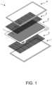
- FIG. 1 is an exploded perspective view of a power generation unit 1 constituting a power generation module of a solid oxide fuel cell 100 (hereinafter, also simply referred to as "fuel cell”) according to the present embodiment.
- the solid oxide fuel cell 100 according to the present embodiment is mainly mounted on a vehicle or the like, but is not limited thereto.
- the power generation unit 1 includes a power generation cell 2, interconnectors 3 made of a metal, and seal members 4 that seal outer edges of the interconnectors 3.
- the interconnectors 3 are joined to both surfaces of an active area 2A which is a region contributing to power generation of the power generation cell 2. Further, the seal members 4 are joined to both surfaces of outer edge portions of the power generation cells 2 (see FIG. 2 ). Details of a method for joining the power generation cell 2 and the interconnector 3 will be described later.
- FIG. 2 is an exploded perspective view in which two power generation units 1 are laminated.
- the solid oxide fuel cell 100 is formed by laminating a plurality of power generation units 1, the solid oxide fuel cell 100 is a stack of the two power generation units 1 in FIG. 2 for convenience.
- a separator 5 is interposed between the two power generation units 1.
- the two power generation units 1 are laminated by metal-joining the interconnector 3 of one power generation unit 1 to one surface of the separator 5 and the interconnector 3 of the other power generation unit 1 to the other surface of the separator 5.
- the two power generation units 1 are laminated in FIG. 2 , more power generation units 1 can be laminated in the same manner.
- FIG. 3 is a view schematically showing a cross section taken along a line III-III in FIG. 2 .
- an outer edge portion of the power generation unit 1 is omitted, and only a part of the cross section is shown in an enlarged manner.
- a power generation unit in a state in which the interconnector 3 is joined to the power generation cell 2 and the separator 5 is referred to as the power generation unit 1.
- the power generation cell 2 includes a membrane electrode assembly 2C in which an anode electrode is disposed on one surface of a solid electrolyte layer and a cathode electrode is disposed on the other surface thereof, a cathode support layer 2B that supports the cathode electrode, and an anode support layer 2D that supports the anode electrode.
- the cathode support layer 2B and the anode support layer 2D are porous metal bodies configured not to inhibit supplies of an anode gas and a cathode gas, respectively, and are formed of, for example, ferritic stainless steel.
- the cathode electrode is disposed on an upper surface side of the membrane electrode assembly 2C, and the anode electrode is disposed on a lower surface side thereof.
- the separator 5 is disposed between two adjacent power generation cells 2 and separated from the cathode support layer (porous metal support layer) 2B and the anode support layer (porous metal support layer) 2D.
- the separator 5 forms an anode flow path 6 for supplying a fuel gas to the anode electrode between the anode support layer 2D of the power generation cell 2 (anode electrode side of the power generation cell 2) and the separator 5.
- the separator 5 forms a cathode flow path 7 for supplying air to the cathode electrode between the cathode support layer 2B of the power generation cell 2 (cathode electrode side of the power generation cell 2) and the separator 5.
- a material constituting the separator 5 is not particularly limited as long as the material is a conductive and thermally conductive material, but for example, an alloy containing iron (Fe) or chromium (Cr), a metal, or the like is used, and ferritic stainless steel is preferably used.
- the interconnector 3 is disposed between the active area 2A of the power generation cell 2 and the separator 5, and connects the separator 5 and the porous metal support layers 2B and 2D.
- the interconnector 3 is a current collecting member having a power collecting function, and also functions as a support member that supports the power generation cell 2 and the separator 5.
- the interconnector 3 includes an anode-side interconnector (anode-side support member) 31 disposed between the anode support layer (porous metal support layer on the anode electrode side) 2D of the power generation cell 2 and the separator 5, and a cathode-side interconnector (cathode-side support member) 32 disposed between the cathode support layer (porous metal support layer on the cathode electrode side) 2B of the power generation cell 2 and the separator 5.
- a material constituting the interconnector 3 is not particularly limited as long as the material is a conductive and thermally conductive material, and for example, ferritic stainless steel containing aluminum or the like is used.
- the anode-side interconnector 31 is a member including a first contact portion 311 that is in contact with an upper surface of the separator 5, a third contact portion 312 that is in contact with a lower surface of the anode support layer 2D, and a connecting portion 313 that connects the first contact portion 311 and the third contact portion 312.
- the anode-side interconnector 31 and the separator 5 are welded at the first contact portion 311, and the anode-side interconnector 31 and the anode support layer 2D are welded at the third contact portion 312.
- laser welding is used as a welding method, but the present invention is not limited thereto.
- a plurality of the anode-side interconnectors 31 are arranged in the anode flow path 6 in a width direction of the separator 5. Accordingly, the anode flow path 6 between the separator 5 and the anode support layer 2D is partitioned into a plurality of flow paths surrounded by the separator 5, the anode-side interconnector 31, and the anode support layer 2D.
- the cathode-side interconnector 32 is a member including a second contact portion 321 that is in contact with a lower surface of the separator 5, a fourth contact portion 322 that is in contact with an upper surface of the cathode support layer 2B, and a connecting portion 323 that connects the second contact portion 321 and the fourth contact portion 322.
- the cathode-side interconnector 32 and the separator 5 are joined to each other at the second contact portion 321 by diffusion joining using a joining material 8 made of a metal, and the cathode-side interconnector 32 and the cathode support layer 2B are welded to each other at the fourth contact portion 322.
- a plurality of the cathode-side interconnectors 32 are arranged in the cathode flow path 7 in the width direction of the separator 5. Accordingly, the cathode flow path 7 between the separator 5 and the cathode support layer 2B is partitioned into a plurality of flow paths surrounded by the separator 5, the cathode-side interconnector 32, and the cathode support layer 2B.
- the separator 5 is provided between the power generation cells 2, is separated from the power generation cells 2, and partitions the anode flow path 6 and the cathode flow path 7, and the interconnector (support member) 3 that connects the separator 5 and the power generation cell 2 is disposed in the anode flow path 6 and the cathode flow path 7.
- a gas flow rate in a cathode flow path through which the air (cathode gas) flows is generally greater than a gas flow rate in an anode flow path through which the fuel gas (anode gas) flows, so that an internal pressure of the cathode flow path becomes higher. Therefore, a relatively large force acts on a joining portion between an interconnector (current collecting member and support member) in the cathode flow path and a separator due to an internal pressure difference between the anode flow path and the cathode flow path, and there is a risk that the interconnector is peeled off and the fuel cell is damaged.
- the spacer reduces a cross-sectional area of a gas flow path (anode flow path and cathode flow path), thereby increasing an internal pressure. Therefore, a reinforcing member is further required, and the weight of the fuel cell is further increased.
- a joining area of a joining portion between the cathode-side interconnector 32 and the separator 5 is larger than that of a joining portion between the anode-side interconnector 31 and the separator 5. Accordingly, a joining force between the cathode-side interconnector 32 and the separator 5 is enhanced, the cathode-side interconnector 32 is prevented from being peeled off from the separator 5, and the fuel cell 100 is prevented from being damaged. Further, since the joining force between the cathode-side interconnector 32 and the separator 5 is improved, the separator 5 can be thinned, and the weight of the fuel cell 100 can be reduced.
- the plurality of the anode-side interconnectors 31 and the plurality of the cathode-side interconnectors 32 are separately arranged at intervals between the separator 5 and the power generation cell 2.
- the interconnectors 3 By arranging the interconnectors 3 at intervals in this manner, flow path cross-sectional areas of the anode flow path 6 and the cathode flow path 7 increase. Since the internal pressure in the flow path decreases when a cross-sectional area increases, it is possible to prevent an increase in internal pressure difference between the anode flow path 6 and the cathode flow path 7 by adjusting a size of the interval between the interconnectors 3.
- the power generation cell 2 includes the anode support layer 2D made of a porous metal body on the anode electrode side and the cathode support layer 2B made of a porous metal body on the cathode electrode side.
- the anode-side interconnector 31 is welded to the anode support layer 2D
- the cathode-side interconnector 32 is welded to the cathode support layer 2B.
- the power generation cell 2 includes the porous metal support layers 2B and 2D, and the porous metal support layers 2B and 2D are joined to the interconnector 3 made of the metal.
- the joining between the interconnector 3 and the power generation cell 2 is joining between a metal and a ceramic.
- the interconnector 3 and the power generation cell 2 are joined to each other by metal joining, joining strength is enhanced as compared with the joining of the ceramic and the metal.
- joining interfaces melt at the time of a heat input, initial surface layers (oxide films) of the interconnector 3 and the porous metal support layers 2B and 2D are broken, resistance of the joining portion decreases, conductivity is improved, and a cost is low because no additional materials are required.
- FIG. 4 is an enlarged view of a portion surrounded by a rectangle A in FIG. 3 .
- the anode-side interconnector 31 is welded to the separator 5 at the first contact portion 311, and a weld portion (first joining portion) 314 is formed in the first contact portion 311.
- the anode-side interconnector 31 is welded to the anode support layer 2D at the third contact portion 312, and a weld portion (third joining portion) 315 is formed in the third contact portion 312.
- the cathode-side interconnector 32 is joined to the separator 5 at the second contact portion 321 by the diffusion joining using the joining material 8 made of the metal, and forms a joining portion (second joining portion) 324 at the second contact portion 321.
- the cathode-side interconnector 32 is joined to the cathode support layer 2B at the fourth contact portion 322 by the welding, and a weld portion (fourth joining portion) 325 is formed in the fourth contact portion 322.
- the diffusion joining between the cathode-side interconnector 32 and the separator 5 is performed by sandwiching the joining material 8 between the cathode-side interconnector 32 and the separator 5, and pressing and heating the joining material 8.
- a joining area of the diffusion joining is larger than that of the welding. Therefore, as shown in FIG. 4 , a joining area of a joining portion (second joining portion) 324 between the cathode-side interconnector 32 and the separator 5 is larger than that of the joining portion (first joining portion) 314 between the anode-side interconnector 31 and the separator 5.
- the joining material 8 having substantially the same surface area as the second contact portion 321 is used. Therefore, a contact area (surface area of the second contact portion 321) between the cathode-side interconnector 32 and the separator 5 and a joining area (surface area of the second joining portion 324) are substantially the same.
- the joining portion (second joining portion) 324 between the cathode-side interconnector 32 and the separator 5 is formed at a position to cover the joining portion (first joining portion) 314 between the anode-side interconnector 31 and the separator 5 as viewed in a lamination direction of the power generation cells 2.
- the joining force between the cathode-side interconnector 32 and the separator 5 is further enhanced. This prevents the cathode-side interconnector 32 from being peeled off from the separator 5. Further, since the joining force between the cathode-side interconnector 32 and the separator 5 is improved, the separator 5 can be thinned, and the weight of the fuel cell 100 can be reduced.
- the joining portion (first joining portion) 314 between the anode-side interconnector 31 and the separator 5 is covered with the joining portion (second joining portion) 324 between the cathode-side interconnector 32 and the separator 5 as viewed in the lamination direction of the power generation cells 2, the first joining portion 314 and a periphery thereof are reinforced by the second joining portion 324.
- a differential pressure between the anode flow path 6 and the cathode flow path 7 is large, there is a risk that a crack or the like will occur in the separator 5 starting from the first joining portion 314 and the periphery thereof.
- the first joining portion 314 and the periphery thereof, which tend to become a starting point of the crack or the like, are reinforced by the second joining portion 324, the deformation of the separator 5 is prevented, and an occurrence of the crack or the like in the separator 5 is prevented. Further, since a weld bead generated in the separator 5 due to the welding of the anode-side interconnector 31 and the separator 5 is covered with the second joining portion 324, oxidative degradation due to the air in the bead portion is prevented.
- the diffusion joining is joining having higher strength during the operation of the fuel cell 100 since a reaction proceeds by the heat input during the operation of the fuel cell 100.
- the joining material 8 used for the diffusion joining may be nickel (Ni), copper (Cu), gold (Au), silver (Ag), platinum (Pt), an alloy containing these, or the like.
- a form of the joining material 8 is not particularly limited, but may be, for example, a paste, a sheet, a wire, a coating, or the like.
- the cathode-side interconnector 32 and the separator 5 are joined by the diffusion joining, but the present invention is not necessarily limited to this, and any joining method other than the welding is not particularly limited.
- the cathode-side interconnector 32 and the separator 5 may be brazed. Even in such a joining method, the joining area becomes larger than that of the welding, and the joining force between the cathode-side interconnector 32 and the separator 5 is further strengthened.
- the solid oxide fuel cell 100 includes the separator 5 provided between the power generation cells 2 and separated from the power generation cells 2, the anode flow path 6 formed between the anode electrode side of the power generation cell 2 and the separator 5, and the cathode flow path 7 formed between the cathode electrode side of the power generation cell 2 and the separator 5.
- the anode-side interconnector (anode-side support member) 31 joined to the separator 5 and the anode electrode side of the power generation cell 2 is provided in the anode flow path 6, and the cathode-side interconnector (cathode-side support member) 32 joined to the separator 5 and the cathode electrode side of the power generation cell 2 is provided in the cathode flow path 7.
- the joining area of the second joining portion 324 at which the cathode-side interconnector (cathode-side support member) 32 is joined to the separator 5 is greater than that of the first joining portion 314 at which the anode-side interconnector (anode-side support member) 31 is joined to the separator 5. Accordingly, the joining force between the cathode-side interconnector 32 and the separator 5 is enhanced, the cathode-side interconnector 32 is prevented from being peeled off from the separator 5, and the fuel cell 100 is prevented from being damaged. Further, since the joining force between the cathode-side interconnector 32 and the separator 5 is improved, the separator 5 can be thinned, and the weight of the fuel cell 100 can be reduced. That is, it is possible to provide the solid oxide fuel cell 100 which is prevented from being damaged and is reduced in weight.
- the electric resistance is proportional to the energizing distance, the electric resistance between the cathode-side interconnector 32 and the separator 5 is reduced by thinning the separator 5, and the power generation efficiency of the solid oxide fuel cell 100 is also improved. Further, by thinning the separator 5, the height of the power generation cells 2 in the lamination direction can be prevented, and the solid oxide fuel cell 100 can be made compact.
- the anode-side interconnector (anode-side support member) 31 and the separator 5 are welded, and the cathode-side interconnector (cathode-side support member) 32 and the separator 5 are joined by the joining method (diffusion joining using a metal or the like) other than the welding. Accordingly, the joining area of the joining portion (second joining portion) 324 between the cathode-side interconnector 32 and the separator 5 is larger than that of the joining portion (first joining portion) 314 between the anode-side interconnector 31 and the separator 5.
- the joining force between the cathode-side interconnector 32 and the separator 5 is strengthened, the cathode-side interconnector 32 is prevented from being peeled off from the separator 5, and the separator 5 can be thinned, so that the weight of the fuel cell 100 can be reduced.
- the joining portion (first joining portion) 314 between the anode-side interconnector 31 and the separator 5 is covered with the joining portion (second joining portion) 324 between the cathode-side interconnector 32 and the separator 5 as viewed in the lamination direction of the power generation cells 2. Accordingly, the first joining portion 314 and the periphery thereof are reinforced by the second joining portion 324. That is, since the first joining portion 314 and the periphery thereof, which tend to become the starting point of the crack or the like, are reinforced by the second joining portion 324, the deformation of the separator 5 is prevented, and the occurrence of the crack or the like in the separator 5 is prevented.
- the plurality of anode-side interconnectors (anode-side support members) 31 and the plurality of cathode-side interconnectors (cathode-side support members) 32 are separately disposed at intervals between the separator 5 and the power generation cell 2. In this way, since the interconnectors 3 are arranged at intervals, the flow path cross-sectional areas of the anode flow path 6 and the cathode flow path 7 increase, and the internal pressure in the flow path decreases.
- the power generation cell 2 includes the cathode support layer (porous metal support layer) 2B on the cathode electrode side, and the cathode-side interconnector (cathode-side support member) 32 and the cathode support layer (porous metal support layer) 2B are metal-joined to each other. Accordingly, joining strength between the power generation cell 2 and the cathode-side interconnector (cathode-side support member) 32 is enhanced as compared with the case in which the power generation cell 2 does not include the cathode support layer (porous metal support layer) 2B (that is, the case in which the metal and the ceramic are joined).
- the power generation cell 2 includes the anode support layer (porous metal support layer) 2D on the anode electrode side, and the anode-side interconnector (anode-side support member) 31 and the anode support layer (porous metal support layer) 2D are metal-joined to each other. Accordingly, joining strength between the power generation cell 2 and the anode-side interconnector (anode-side support member) 31 is enhanced as compared with the case in which the power generation cell 2 does not include the anode support layer (porous metal support layer) 2D (that is, the case in which the metal and the ceramic are joined).
- a positional relationship among the anode-side interconnector (anode-side support member) 31, the cathode-side interconnector (cathode-side support member) 32, and the separator 5, a positional relationship among the joining portions, and the like shown in the present embodiment are preferred embodiments, and are not necessarily limited thereto. If the joining area of the second joining portion in the cathode flow path 7 is larger than that of the first joining portion in the anode flow path 6, the joining force between the cathode-side interconnector 32 and the separator 5 is further strengthened, and the separator 5 can be thinned. That is, it is possible to obtain effects of strengthening the joining force between the members and reducing the weight.
- the power generation cell 2 preferably includes the porous metal support layers 2B and 2D on the anode electrode side and the cathode electrode side, but is not necessarily limited thereto, and may have a configuration in which the porous metal support layer is provided only on one of the anode electrode side or the cathode electrode side, or a configuration in which the porous metal support layer is not provided.
Landscapes
- Life Sciences & Earth Sciences (AREA)
- Engineering & Computer Science (AREA)
- Manufacturing & Machinery (AREA)
- Sustainable Development (AREA)
- Sustainable Energy (AREA)
- Chemical & Material Sciences (AREA)
- Chemical Kinetics & Catalysis (AREA)
- Electrochemistry (AREA)
- General Chemical & Material Sciences (AREA)
- Fuel Cell (AREA)
Abstract
Description
- The present invention relates to a solid oxide fuel cell.
-
JP 2019-200878 A - Although a fuel cell is provided with an anode flow path through which a fuel gas (anode gas) flows and a cathode flow path through which air (cathode gas) flows, a gas flow rate in the cathode flow path is generally higher than a gas flow rate in the anode flow path, and thus an internal pressure in the cathode flow path is higher. Therefore, in the fuel cell stack described in
JP 2019-200878 A - On the other hand, in the case in which a thickness of the separator is increased to prevent deformation of the separator so as to enhance a joining force with the current collecting member, the entire fuel cell stack becomes heavy.
- The present invention has been made in view of the above problems, and an object thereof is to provide a solid oxide fuel cell that is reduced in weight while preventing damage to the fuel cell.
- According to an aspect of this invention, there is provided a solid oxide fuel cell that includes a plurality of laminated power generation cells each including a solid electrolyte layer, an anode electrode disposed on one surface of the solid electrolyte layer, and a cathode electrode disposed on the other surface of the solid electrolyte layer, a separator provided between the power generation cells and separated from the power generation cells, an anode flow path formed between an anode electrode side of the power generation cell and the separator, and a cathode flow path formed between a cathode electrode side of the power generation cell and the separator. An anode-side support member joined to the separator and the anode electrode side of the power generation cell is provided in the anode flow path, a cathode-side support member joined to the separator and the cathode electrode side of the power generation cell is provided in the cathode flow path, and a joining area of a second joining portion at which the cathode-side support member and the separator are joined is greater than a joining area of a first joining portion at which the anode-side support member and the separator are joined.
-
- [
FIG. 1] FIG. 1 is an exploded perspective view of a fuel cell stack according to an embodiment of the present invention. - [
FIG. 2] FIG. 2 is an exploded perspective view of a portion in which power generation units inFIG. 1 are laminated. - [
FIG. 3] FIG. 3 is a schematic cross-sectional view taken along a line III-III inFIG. 2 . - [
FIG. 4] FIG. 4 is an enlarged view of a portion surrounded by a rectangle A inFIG. 3 . - Hereinafter, embodiments of the present invention will be described with reference to the drawings and the like.
-
FIG. 1 is an exploded perspective view of apower generation unit 1 constituting a power generation module of a solid oxide fuel cell 100 (hereinafter, also simply referred to as "fuel cell") according to the present embodiment. The solidoxide fuel cell 100 according to the present embodiment is mainly mounted on a vehicle or the like, but is not limited thereto. - The
power generation unit 1 includes apower generation cell 2,interconnectors 3 made of a metal, andseal members 4 that seal outer edges of theinterconnectors 3. Theinterconnectors 3 are joined to both surfaces of an active area 2A which is a region contributing to power generation of thepower generation cell 2. Further, theseal members 4 are joined to both surfaces of outer edge portions of the power generation cells 2 (seeFIG. 2 ). Details of a method for joining thepower generation cell 2 and theinterconnector 3 will be described later. -
FIG. 2 is an exploded perspective view in which twopower generation units 1 are laminated. Although the solidoxide fuel cell 100 is formed by laminating a plurality ofpower generation units 1, the solidoxide fuel cell 100 is a stack of the twopower generation units 1 inFIG. 2 for convenience. - As shown in
FIG. 2 , aseparator 5 is interposed between the twopower generation units 1. The twopower generation units 1 are laminated by metal-joining theinterconnector 3 of onepower generation unit 1 to one surface of theseparator 5 and theinterconnector 3 of the otherpower generation unit 1 to the other surface of theseparator 5. Although the twopower generation units 1 are laminated inFIG. 2 , morepower generation units 1 can be laminated in the same manner. -
FIG. 3 is a view schematically showing a cross section taken along a line III-III inFIG. 2 . InFIG. 3 , for the sake of simplicity, an outer edge portion of thepower generation unit 1 is omitted, and only a part of the cross section is shown in an enlarged manner. Here, a power generation unit in a state in which theinterconnector 3 is joined to thepower generation cell 2 and theseparator 5 is referred to as thepower generation unit 1. - As shown in
FIG. 3 , thepower generation cell 2 includes amembrane electrode assembly 2C in which an anode electrode is disposed on one surface of a solid electrolyte layer and a cathode electrode is disposed on the other surface thereof, acathode support layer 2B that supports the cathode electrode, and ananode support layer 2D that supports the anode electrode. Thecathode support layer 2B and theanode support layer 2D are porous metal bodies configured not to inhibit supplies of an anode gas and a cathode gas, respectively, and are formed of, for example, ferritic stainless steel. InFIG. 3 , the cathode electrode is disposed on an upper surface side of themembrane electrode assembly 2C, and the anode electrode is disposed on a lower surface side thereof. - The
separator 5 is disposed between two adjacentpower generation cells 2 and separated from the cathode support layer (porous metal support layer) 2B and the anode support layer (porous metal support layer) 2D. Theseparator 5 forms ananode flow path 6 for supplying a fuel gas to the anode electrode between theanode support layer 2D of the power generation cell 2 (anode electrode side of the power generation cell 2) and theseparator 5. Further, theseparator 5 forms acathode flow path 7 for supplying air to the cathode electrode between thecathode support layer 2B of the power generation cell 2 (cathode electrode side of the power generation cell 2) and theseparator 5. A material constituting theseparator 5 is not particularly limited as long as the material is a conductive and thermally conductive material, but for example, an alloy containing iron (Fe) or chromium (Cr), a metal, or the like is used, and ferritic stainless steel is preferably used. - The
interconnector 3 is disposed between the active area 2A of thepower generation cell 2 and theseparator 5, and connects theseparator 5 and the porousmetal support layers interconnector 3 is a current collecting member having a power collecting function, and also functions as a support member that supports thepower generation cell 2 and theseparator 5. - The
interconnector 3 includes an anode-side interconnector (anode-side support member) 31 disposed between the anode support layer (porous metal support layer on the anode electrode side) 2D of thepower generation cell 2 and theseparator 5, and a cathode-side interconnector (cathode-side support member) 32 disposed between the cathode support layer (porous metal support layer on the cathode electrode side) 2B of thepower generation cell 2 and theseparator 5. A material constituting theinterconnector 3 is not particularly limited as long as the material is a conductive and thermally conductive material, and for example, ferritic stainless steel containing aluminum or the like is used. - The anode-
side interconnector 31 is a member including afirst contact portion 311 that is in contact with an upper surface of theseparator 5, athird contact portion 312 that is in contact with a lower surface of theanode support layer 2D, and a connectingportion 313 that connects thefirst contact portion 311 and thethird contact portion 312. The anode-side interconnector 31 and theseparator 5 are welded at thefirst contact portion 311, and the anode-side interconnector 31 and theanode support layer 2D are welded at thethird contact portion 312. In the present embodiment, laser welding is used as a welding method, but the present invention is not limited thereto. - A plurality of the anode-
side interconnectors 31 are arranged in theanode flow path 6 in a width direction of theseparator 5. Accordingly, theanode flow path 6 between theseparator 5 and theanode support layer 2D is partitioned into a plurality of flow paths surrounded by theseparator 5, the anode-side interconnector 31, and theanode support layer 2D. - The cathode-
side interconnector 32 is a member including asecond contact portion 321 that is in contact with a lower surface of theseparator 5, afourth contact portion 322 that is in contact with an upper surface of thecathode support layer 2B, and a connectingportion 323 that connects thesecond contact portion 321 and thefourth contact portion 322. Here, the cathode-side interconnector 32 and theseparator 5 are joined to each other at thesecond contact portion 321 by diffusion joining using a joiningmaterial 8 made of a metal, and the cathode-side interconnector 32 and thecathode support layer 2B are welded to each other at thefourth contact portion 322. - A plurality of the cathode-
side interconnectors 32 are arranged in thecathode flow path 7 in the width direction of theseparator 5. Accordingly, thecathode flow path 7 between theseparator 5 and thecathode support layer 2B is partitioned into a plurality of flow paths surrounded by theseparator 5, the cathode-side interconnector 32, and thecathode support layer 2B. - As described above, in the solid
oxide fuel cell 100, theseparator 5 is provided between thepower generation cells 2, is separated from thepower generation cells 2, and partitions theanode flow path 6 and thecathode flow path 7, and the interconnector (support member) 3 that connects theseparator 5 and thepower generation cell 2 is disposed in theanode flow path 6 and thecathode flow path 7. - In the fuel cell, a gas flow rate in a cathode flow path through which the air (cathode gas) flows is generally greater than a gas flow rate in an anode flow path through which the fuel gas (anode gas) flows, so that an internal pressure of the cathode flow path becomes higher. Therefore, a relatively large force acts on a joining portion between an interconnector (current collecting member and support member) in the cathode flow path and a separator due to an internal pressure difference between the anode flow path and the cathode flow path, and there is a risk that the interconnector is peeled off and the fuel cell is damaged.
- On the other hand, in the case in which a thickness of the separator is increased to prevent deformation of the separator so as to enhance a joining force between the interconnector and the separator, a weight of the entire fuel cell is increased.
- In the case in which a spacer is provided between the interconnector and the separator and the deformation of the separator is prevented by absorbing a force in a lamination direction of the power generation cell, the spacer reduces a cross-sectional area of a gas flow path (anode flow path and cathode flow path), thereby increasing an internal pressure. Therefore, a reinforcing member is further required, and the weight of the fuel cell is further increased.
- Therefore, in the present embodiment, a joining area of a joining portion between the cathode-
side interconnector 32 and theseparator 5 is larger than that of a joining portion between the anode-side interconnector 31 and theseparator 5. Accordingly, a joining force between the cathode-side interconnector 32 and theseparator 5 is enhanced, the cathode-side interconnector 32 is prevented from being peeled off from theseparator 5, and thefuel cell 100 is prevented from being damaged. Further, since the joining force between the cathode-side interconnector 32 and theseparator 5 is improved, theseparator 5 can be thinned, and the weight of thefuel cell 100 can be reduced. - Hereinafter, referring to
FIGS. 3 and 4 , details of joining of theinterconnector 3 to theseparator 5 and joining of theinterconnector 3 to thepower generation cell 2 will be described. - As shown in
FIG. 3 , the plurality of the anode-side interconnectors 31 and the plurality of the cathode-side interconnectors 32 are separately arranged at intervals between theseparator 5 and thepower generation cell 2. By arranging theinterconnectors 3 at intervals in this manner, flow path cross-sectional areas of theanode flow path 6 and thecathode flow path 7 increase. Since the internal pressure in the flow path decreases when a cross-sectional area increases, it is possible to prevent an increase in internal pressure difference between theanode flow path 6 and thecathode flow path 7 by adjusting a size of the interval between theinterconnectors 3. - As described above, the
power generation cell 2 includes theanode support layer 2D made of a porous metal body on the anode electrode side and thecathode support layer 2B made of a porous metal body on the cathode electrode side. The anode-side interconnector 31 is welded to theanode support layer 2D, and the cathode-side interconnector 32 is welded to thecathode support layer 2B. In this way, thepower generation cell 2 includes the porous metal support layers 2B and 2D, and the porous metal support layers 2B and 2D are joined to theinterconnector 3 made of the metal. Here, in the case in which thepower generation cell 2 does not include the porous metal support layers 2B and 2D, the joining between theinterconnector 3 and thepower generation cell 2 is joining between a metal and a ceramic. On the other hand, in the present embodiment, since theinterconnector 3 and thepower generation cell 2 are joined to each other by metal joining, joining strength is enhanced as compared with the joining of the ceramic and the metal. Further, in the welding, since joining interfaces melt at the time of a heat input, initial surface layers (oxide films) of theinterconnector 3 and the porous metal support layers 2B and 2D are broken, resistance of the joining portion decreases, conductivity is improved, and a cost is low because no additional materials are required. -
FIG. 4 is an enlarged view of a portion surrounded by a rectangle A inFIG. 3 . - As shown in
FIG. 4 , the anode-side interconnector 31 is welded to theseparator 5 at thefirst contact portion 311, and a weld portion (first joining portion) 314 is formed in thefirst contact portion 311. As described above, the anode-side interconnector 31 is welded to theanode support layer 2D at thethird contact portion 312, and a weld portion (third joining portion) 315 is formed in thethird contact portion 312. - On the other hand, the cathode-
side interconnector 32 is joined to theseparator 5 at thesecond contact portion 321 by the diffusion joining using the joiningmaterial 8 made of the metal, and forms a joining portion (second joining portion) 324 at thesecond contact portion 321. As described above, the cathode-side interconnector 32 is joined to thecathode support layer 2B at thefourth contact portion 322 by the welding, and a weld portion (fourth joining portion) 325 is formed in thefourth contact portion 322. Here, the diffusion joining between the cathode-side interconnector 32 and theseparator 5 is performed by sandwiching the joiningmaterial 8 between the cathode-side interconnector 32 and theseparator 5, and pressing and heating the joiningmaterial 8. Further, a joining area of the diffusion joining is larger than that of the welding. Therefore, as shown inFIG. 4 , a joining area of a joining portion (second joining portion) 324 between the cathode-side interconnector 32 and theseparator 5 is larger than that of the joining portion (first joining portion) 314 between the anode-side interconnector 31 and theseparator 5. In the present embodiment, the joiningmaterial 8 having substantially the same surface area as thesecond contact portion 321 is used. Therefore, a contact area (surface area of the second contact portion 321) between the cathode-side interconnector 32 and theseparator 5 and a joining area (surface area of the second joining portion 324) are substantially the same. Further, in the present embodiment, the joining portion (second joining portion) 324 between the cathode-side interconnector 32 and theseparator 5 is formed at a position to cover the joining portion (first joining portion) 314 between the anode-side interconnector 31 and theseparator 5 as viewed in a lamination direction of thepower generation cells 2. - As described above, since the joining area of the second joining
portion 324 in thecathode flow path 7 is larger than the joining area of the first joiningportion 314 in theanode flow path 6, the joining force between the cathode-side interconnector 32 and theseparator 5 is further enhanced. This prevents the cathode-side interconnector 32 from being peeled off from theseparator 5. Further, since the joining force between the cathode-side interconnector 32 and theseparator 5 is improved, theseparator 5 can be thinned, and the weight of thefuel cell 100 can be reduced. Since electric resistance is proportional to an energizing distance, electric resistance between the cathode-side interconnector 32 and theseparator 5 is reduced by thinning theseparator 5, and power generation efficiency of thefuel cell 100 is also improved. Furthermore, by thinning theseparator 5, a height of thepower generation cells 2 in the lamination direction can be prevented, and the solidoxide fuel cell 100 can be made compact. - Since the joining portion (first joining portion) 314 between the anode-
side interconnector 31 and theseparator 5 is covered with the joining portion (second joining portion) 324 between the cathode-side interconnector 32 and theseparator 5 as viewed in the lamination direction of thepower generation cells 2, the first joiningportion 314 and a periphery thereof are reinforced by the second joiningportion 324. Here, when a differential pressure between theanode flow path 6 and thecathode flow path 7 is large, there is a risk that a crack or the like will occur in theseparator 5 starting from the first joiningportion 314 and the periphery thereof. On the other hand, in the present embodiment, since the first joiningportion 314 and the periphery thereof, which tend to become a starting point of the crack or the like, are reinforced by the second joiningportion 324, the deformation of theseparator 5 is prevented, and an occurrence of the crack or the like in theseparator 5 is prevented. Further, since a weld bead generated in theseparator 5 due to the welding of the anode-side interconnector 31 and theseparator 5 is covered with the second joiningportion 324, oxidative degradation due to the air in the bead portion is prevented. - The diffusion joining is joining having higher strength during the operation of the
fuel cell 100 since a reaction proceeds by the heat input during the operation of thefuel cell 100. The joiningmaterial 8 used for the diffusion joining may be nickel (Ni), copper (Cu), gold (Au), silver (Ag), platinum (Pt), an alloy containing these, or the like. A form of the joiningmaterial 8 is not particularly limited, but may be, for example, a paste, a sheet, a wire, a coating, or the like. - In the present embodiment, the cathode-
side interconnector 32 and theseparator 5 are joined by the diffusion joining, but the present invention is not necessarily limited to this, and any joining method other than the welding is not particularly limited. For example, the cathode-side interconnector 32 and theseparator 5 may be brazed. Even in such a joining method, the joining area becomes larger than that of the welding, and the joining force between the cathode-side interconnector 32 and theseparator 5 is further strengthened. - According to the solid
oxide fuel cell 100 of the embodiment described above, the following effects can be obtained. - The solid
oxide fuel cell 100 includes theseparator 5 provided between thepower generation cells 2 and separated from thepower generation cells 2, theanode flow path 6 formed between the anode electrode side of thepower generation cell 2 and theseparator 5, and thecathode flow path 7 formed between the cathode electrode side of thepower generation cell 2 and theseparator 5. The anode-side interconnector (anode-side support member) 31 joined to theseparator 5 and the anode electrode side of thepower generation cell 2 is provided in theanode flow path 6, and the cathode-side interconnector (cathode-side support member) 32 joined to theseparator 5 and the cathode electrode side of thepower generation cell 2 is provided in thecathode flow path 7. Further, the joining area of the second joiningportion 324 at which the cathode-side interconnector (cathode-side support member) 32 is joined to theseparator 5 is greater than that of the first joiningportion 314 at which the anode-side interconnector (anode-side support member) 31 is joined to theseparator 5. Accordingly, the joining force between the cathode-side interconnector 32 and theseparator 5 is enhanced, the cathode-side interconnector 32 is prevented from being peeled off from theseparator 5, and thefuel cell 100 is prevented from being damaged. Further, since the joining force between the cathode-side interconnector 32 and theseparator 5 is improved, theseparator 5 can be thinned, and the weight of thefuel cell 100 can be reduced. That is, it is possible to provide the solidoxide fuel cell 100 which is prevented from being damaged and is reduced in weight. - Since the electric resistance is proportional to the energizing distance, the electric resistance between the cathode-
side interconnector 32 and theseparator 5 is reduced by thinning theseparator 5, and the power generation efficiency of the solidoxide fuel cell 100 is also improved. Further, by thinning theseparator 5, the height of thepower generation cells 2 in the lamination direction can be prevented, and the solidoxide fuel cell 100 can be made compact. - In the solid
oxide fuel cell 100, the anode-side interconnector (anode-side support member) 31 and theseparator 5 are welded, and the cathode-side interconnector (cathode-side support member) 32 and theseparator 5 are joined by the joining method (diffusion joining using a metal or the like) other than the welding. Accordingly, the joining area of the joining portion (second joining portion) 324 between the cathode-side interconnector 32 and theseparator 5 is larger than that of the joining portion (first joining portion) 314 between the anode-side interconnector 31 and theseparator 5. Therefore, the joining force between the cathode-side interconnector 32 and theseparator 5 is strengthened, the cathode-side interconnector 32 is prevented from being peeled off from theseparator 5, and theseparator 5 can be thinned, so that the weight of thefuel cell 100 can be reduced. - In the solid
oxide fuel cell 100, the joining portion (first joining portion) 314 between the anode-side interconnector 31 and theseparator 5 is covered with the joining portion (second joining portion) 324 between the cathode-side interconnector 32 and theseparator 5 as viewed in the lamination direction of thepower generation cells 2. Accordingly, the first joiningportion 314 and the periphery thereof are reinforced by the second joiningportion 324. That is, since the first joiningportion 314 and the periphery thereof, which tend to become the starting point of the crack or the like, are reinforced by the second joiningportion 324, the deformation of theseparator 5 is prevented, and the occurrence of the crack or the like in theseparator 5 is prevented. - Further, since the weld bead generated in the
separator 5 due to the welding of the anode-side interconnector 31 and theseparator 5 is covered with the second joiningportion 324, the oxidative degradation due to the air in the bead portion is prevented. - In the solid
oxide fuel cell 100, the plurality of anode-side interconnectors (anode-side support members) 31 and the plurality of cathode-side interconnectors (cathode-side support members) 32 are separately disposed at intervals between theseparator 5 and thepower generation cell 2. In this way, since theinterconnectors 3 are arranged at intervals, the flow path cross-sectional areas of theanode flow path 6 and thecathode flow path 7 increase, and the internal pressure in the flow path decreases. Therefore, by adjusting the size of the interval between theinterconnectors 3, it is possible to reduce the differential pressure between theanode flow path 6 and thecathode flow path 7, and it is possible to prevent peeling of the joining between thepower generation cell 2 and the interconnector (support member) 3 and the joining between the interconnector (support member) 3 and theseparator 5. - In the solid
oxide fuel cell 100, thepower generation cell 2 includes the cathode support layer (porous metal support layer) 2B on the cathode electrode side, and the cathode-side interconnector (cathode-side support member) 32 and the cathode support layer (porous metal support layer) 2B are metal-joined to each other. Accordingly, joining strength between thepower generation cell 2 and the cathode-side interconnector (cathode-side support member) 32 is enhanced as compared with the case in which thepower generation cell 2 does not include the cathode support layer (porous metal support layer) 2B (that is, the case in which the metal and the ceramic are joined). - In the solid
oxide fuel cell 100, thepower generation cell 2 includes the anode support layer (porous metal support layer) 2D on the anode electrode side, and the anode-side interconnector (anode-side support member) 31 and the anode support layer (porous metal support layer) 2D are metal-joined to each other. Accordingly, joining strength between thepower generation cell 2 and the anode-side interconnector (anode-side support member) 31 is enhanced as compared with the case in which thepower generation cell 2 does not include the anode support layer (porous metal support layer) 2D (that is, the case in which the metal and the ceramic are joined). - A positional relationship among the anode-side interconnector (anode-side support member) 31, the cathode-side interconnector (cathode-side support member) 32, and the
separator 5, a positional relationship among the joining portions, and the like shown in the present embodiment are preferred embodiments, and are not necessarily limited thereto. If the joining area of the second joining portion in thecathode flow path 7 is larger than that of the first joining portion in theanode flow path 6, the joining force between the cathode-side interconnector 32 and theseparator 5 is further strengthened, and theseparator 5 can be thinned. That is, it is possible to obtain effects of strengthening the joining force between the members and reducing the weight. - As in the present embodiment, the
power generation cell 2 preferably includes the porous metal support layers 2B and 2D on the anode electrode side and the cathode electrode side, but is not necessarily limited thereto, and may have a configuration in which the porous metal support layer is provided only on one of the anode electrode side or the cathode electrode side, or a configuration in which the porous metal support layer is not provided. - Although the embodiment of the present invention has been described above, the above-mentioned embodiment is merely a part of application examples of the present invention, and is not intend to limit the technical scope of the present invention to the specific configurations of the above-mentioned embodiment.
Claims (6)
- A solid oxide fuel cell comprising:a plurality of laminated power generation cells each including a solid electrolyte layer, an anode electrode disposed on one surface of the solid electrolyte layer, and a cathode electrode disposed on the other surface of the solid electrolyte layer;a separator provided between the power generation cells and separated from the power generation cells;an anode flow path formed between an anode electrode side of the power generation cell and the separator; anda cathode flow path formed between a cathode electrode side of the power generation cell and the separator, whereinan anode-side support member joined to the separator and the anode electrode side of the power generation cell is provided in the anode flow path,a cathode-side support member joined to the separator and the cathode electrode side of the power generation cell is provided in the cathode flow path, anda joining area of a second joining portion at which the cathode-side support member and the separator are joined is greater than a joining area of a first joining portion at which the anode-side support member and the separator are joined.
- The solid oxide fuel cell according to claim 1, whereinthe anode-side support member and the separator are welded to each other at the first joining portion, andthe cathode-side support member and the separator are joined at the second joining portion by a joining method other than welding.
- The solid oxide fuel cell according to claim 1 or 2, wherein
the first joining portion is covered with the second joining portion as viewed in a lamination direction of the power generation cells. - The solid oxide fuel cell according to any one of claims 1 to 3, wherein
a plurality of the anode-side support members and a plurality of the cathode-side support members are separately disposed at intervals between the separator and the power generation cell. - The solid oxide fuel cell according to any one of claims 1 to 4, whereinthe power generation cell further includes a porous metal support layer on the cathode electrode side, andthe cathode-side support member and the porous metal support layer are metal-joined to each other.
- The solid oxide fuel cell according to any one of claims 1 to 5, whereinthe power generation cell further includes a porous metal support layer on the anode electrode side, andthe anode-side support member and the porous metal support layer on the anode electrode side are metal-joined to each other.
Applications Claiming Priority (1)
| Application Number | Priority Date | Filing Date | Title |
|---|---|---|---|
| PCT/JP2021/048054 WO2023119603A1 (en) | 2021-12-23 | 2021-12-23 | Solid oxide fuel battery |
Publications (1)
| Publication Number | Publication Date |
|---|---|
| EP4456208A1 true EP4456208A1 (en) | 2024-10-30 |
Family
ID=86901866
Family Applications (1)
| Application Number | Title | Priority Date | Filing Date |
|---|---|---|---|
| EP21969036.9A Withdrawn EP4456208A1 (en) | 2021-12-23 | 2021-12-23 | Solid oxide fuel battery |
Country Status (5)
| Country | Link |
|---|---|
| US (1) | US20250070193A1 (en) |
| EP (1) | EP4456208A1 (en) |
| JP (1) | JP7718508B2 (en) |
| CN (1) | CN118541835A (en) |
| WO (1) | WO2023119603A1 (en) |
Families Citing this family (1)
| Publication number | Priority date | Publication date | Assignee | Title |
|---|---|---|---|---|
| WO2025057406A1 (en) * | 2023-09-15 | 2025-03-20 | 日産自動車株式会社 | Fuel cell |
Family Cites Families (6)
| Publication number | Priority date | Publication date | Assignee | Title |
|---|---|---|---|---|
| EP0446680A1 (en) * | 1990-03-15 | 1991-09-18 | Asea Brown Boveri Ag | Current collector for conducting current between neighbouring piled high temperature fuel cells |
| DE102005022894A1 (en) * | 2005-05-18 | 2006-11-23 | Staxera Gmbh | SOFC stack |
| JP5284921B2 (en) * | 2009-01-28 | 2013-09-11 | 日本碍子株式会社 | Reactor and method for producing reactor |
| JP7070017B2 (en) * | 2018-04-19 | 2022-05-18 | 日産自動車株式会社 | How to reinforce the cell unit and metal support cell |
| JP6805203B2 (en) | 2018-05-15 | 2020-12-23 | 森村Sofcテクノロジー株式会社 | Electrochemical reaction unit and electrochemical reaction cell stack |
| JP6781188B2 (en) * | 2018-05-15 | 2020-11-04 | 森村Sofcテクノロジー株式会社 | Electrochemical reaction unit and electrochemical reaction cell stack |
-
2021
- 2021-12-23 EP EP21969036.9A patent/EP4456208A1/en not_active Withdrawn
- 2021-12-23 WO PCT/JP2021/048054 patent/WO2023119603A1/en not_active Ceased
- 2021-12-23 US US18/721,294 patent/US20250070193A1/en active Pending
- 2021-12-23 CN CN202180105113.6A patent/CN118541835A/en active Pending
- 2021-12-23 JP JP2023568973A patent/JP7718508B2/en active Active
Also Published As
| Publication number | Publication date |
|---|---|
| JPWO2023119603A1 (en) | 2023-06-29 |
| JP7718508B2 (en) | 2025-08-05 |
| WO2023119603A1 (en) | 2023-06-29 |
| CN118541835A (en) | 2024-08-23 |
| US20250070193A1 (en) | 2025-02-27 |
Similar Documents
| Publication | Publication Date | Title |
|---|---|---|
| JP6366086B2 (en) | Fuel cell stack | |
| JP5679893B2 (en) | Solid oxide fuel cell and method for producing the same | |
| JP4666279B2 (en) | Solid oxide fuel cell stack and solid oxide fuel cell | |
| JP4897928B2 (en) | Polymer electrolyte fuel cell and separator for polymer electrolyte fuel cell | |
| JP5267774B2 (en) | Fuel cell separator | |
| JP2006120589A (en) | Flat plate fuel cell | |
| JP7294522B2 (en) | FUEL CELL AND FUEL CELL MANUFACTURING METHOD | |
| US20250070193A1 (en) | Solid oxide fuel cell | |
| JP2016091849A (en) | Fuel cell separator, fuel cell and fuel cell | |
| JP4664030B2 (en) | Fuel cell stack | |
| JP2006294453A (en) | Fuel cell separator | |
| JP2009170273A (en) | Fuel cell | |
| JP2015002022A (en) | Fuel cell stack and manufacturing method therefor | |
| JP2019200878A (en) | Electrochemical reaction unit and electrochemical reaction cell stack | |
| JP4073750B2 (en) | Manufacturing method of diffusion layer separator assembly | |
| EP4456207A1 (en) | Solid oxide fuel cell | |
| JP2009152134A (en) | Fuel cell | |
| EP4354563A1 (en) | Solid oxide fuel cell and method for producing solid oxide fuel cell | |
| JP2019192363A (en) | Cell unit and metal support cell reinforcing method | |
| JP2026080729A (en) | Fuel cell stack | |
| JPWO2023119602A5 (en) | ||
| JP2017216255A (en) | Fuel cell stack | |
| JP2007311079A (en) | Fuel cell stack | |
| CN120164978A (en) | Fuel cell stack | |
| JP2012174626A (en) | Fuel cell |
Legal Events
| Date | Code | Title | Description |
|---|---|---|---|
| STAA | Information on the status of an ep patent application or granted ep patent |
Free format text: STATUS: THE INTERNATIONAL PUBLICATION HAS BEEN MADE |
|
| PUAI | Public reference made under article 153(3) epc to a published international application that has entered the european phase |
Free format text: ORIGINAL CODE: 0009012 |
|
| STAA | Information on the status of an ep patent application or granted ep patent |
Free format text: STATUS: REQUEST FOR EXAMINATION WAS MADE |
|
| 17P | Request for examination filed |
Effective date: 20240701 |
|
| AK | Designated contracting states |
Kind code of ref document: A1 Designated state(s): AL AT BE BG CH CY CZ DE DK EE ES FI FR GB GR HR HU IE IS IT LI LT LU LV MC MK MT NL NO PL PT RO RS SE SI SK SM TR |
|
| DAV | Request for validation of the european patent (deleted) | ||
| DAX | Request for extension of the european patent (deleted) | ||
| STAA | Information on the status of an ep patent application or granted ep patent |
Free format text: STATUS: THE APPLICATION HAS BEEN WITHDRAWN |
|
| 18W | Application withdrawn |
Effective date: 20250424 |