EP4456102A1 - Electronic device and method for manufacturing electronic device - Google Patents
Electronic device and method for manufacturing electronic device Download PDFInfo
- Publication number
- EP4456102A1 EP4456102A1 EP22910958.2A EP22910958A EP4456102A1 EP 4456102 A1 EP4456102 A1 EP 4456102A1 EP 22910958 A EP22910958 A EP 22910958A EP 4456102 A1 EP4456102 A1 EP 4456102A1
- Authority
- EP
- European Patent Office
- Prior art keywords
- operation button
- flange
- opening
- extension portion
- orientation
- Prior art date
- Legal status (The legal status is an assumption and is not a legal conclusion. Google has not performed a legal analysis and makes no representation as to the accuracy of the status listed.)
- Pending
Links
Images



Classifications
-
- H—ELECTRICITY
- H01—ELECTRIC ELEMENTS
- H01H—ELECTRIC SWITCHES; RELAYS; SELECTORS; EMERGENCY PROTECTIVE DEVICES
- H01H13/00—Switches having rectilinearly-movable operating part or parts adapted for pushing or pulling in one direction only, e.g. push-button switch
- H01H13/70—Switches having rectilinearly-movable operating part or parts adapted for pushing or pulling in one direction only, e.g. push-button switch having a plurality of operating members associated with different sets of contacts, e.g. keyboard
- H01H13/702—Switches having rectilinearly-movable operating part or parts adapted for pushing or pulling in one direction only, e.g. push-button switch having a plurality of operating members associated with different sets of contacts, e.g. keyboard with contacts carried by or formed from layers in a multilayer structure, e.g. membrane switches
- H01H13/705—Switches having rectilinearly-movable operating part or parts adapted for pushing or pulling in one direction only, e.g. push-button switch having a plurality of operating members associated with different sets of contacts, e.g. keyboard with contacts carried by or formed from layers in a multilayer structure, e.g. membrane switches characterised by construction, mounting or arrangement of operating parts, e.g. push-buttons or keys
-
- G—PHYSICS
- G05—CONTROLLING; REGULATING
- G05G—CONTROL DEVICES OR SYSTEMS INSOFAR AS CHARACTERISED BY MECHANICAL FEATURES ONLY
- G05G1/00—Controlling members, e.g. knobs or handles; Assemblies or arrangements thereof; Indicating position of controlling members
- G05G1/02—Controlling members for hand actuation by linear movement, e.g. push buttons
-
- H—ELECTRICITY
- H01—ELECTRIC ELEMENTS
- H01H—ELECTRIC SWITCHES; RELAYS; SELECTORS; EMERGENCY PROTECTIVE DEVICES
- H01H2221/00—Actuators
- H01H2221/024—Transmission element
- H01H2221/026—Guiding or lubricating nylon
-
- H—ELECTRICITY
- H01—ELECTRIC ELEMENTS
- H01H—ELECTRIC SWITCHES; RELAYS; SELECTORS; EMERGENCY PROTECTIVE DEVICES
- H01H2233/00—Key modules
- H01H2233/03—Key modules mounted on support plate or frame
- H01H2233/032—Locating pins
-
- H—ELECTRICITY
- H01—ELECTRIC ELEMENTS
- H01H—ELECTRIC SWITCHES; RELAYS; SELECTORS; EMERGENCY PROTECTIVE DEVICES
- H01H2300/00—Orthogonal indexing scheme relating to electric switches, relays, selectors or emergency protective devices covered by H01H
- H01H2300/042—Application rejection, i.e. preventing improper installation of parts
Definitions
- the present invention relates to an electronic device and a method for manufacturing an electronic device.
- an electronic desktop computer (calculator) is widely used for simple calculation.
- a key arrangement is determined and a key touch is devised so that a quick and accurate input operation can be performed in office applications such as performing a large number of calculations (see, for example, Patent Literature 1).
- Patent Literature 1 JPH05-128938A
- a leg portion is provided to protrude around a keytop.
- the leg portion prevents the keytop from protruding from the housing by engagement with a peripheral portion of an opening of the housing. Since the leg portions are provided to protrude at four positions in a vertically and horizontally symmetrical manner, the keytop may be assembled upside down when the keytop is assembled to the housing.
- the present invention has been made in view of the above circumstances, and an object thereof is to prevent an operation button from being assembled to a housing in a wrong orientation.
- an electronic device includes:
- the electronic device is a scientific electronic calculator
- the present invention is not limited to a case where the electronic device is a scientific electronic calculator, and is applied to any electronic device as long as the electronic device is an electronic device including an operation button that is inserted into an opening of a device case so as to be pressed.
- FIG. 1 is a perspective view of a scientific electronic calculator as an example of an electronic device according to the present embodiment.
- a scientific electronic calculator 100 includes a display 10 and an input key group 2 including various key groups.
- the input key group 2 is a key group for receiving an input operation of a mathematical expression component such as a numerical value, a calculation symbol, or the like from a user or receiving instruction operations of various processes, and includes a plurality of keys (a numeric key, a cursor key, an AC key, a CODE key, a SHIFT key, and the like) to which specific functions are assigned.
- the display 10 is, for example, a liquid crystal display (LCD), and is a display unit that displays various data such as characters, codes, symbols, mathematical expressions, calculation results, and tables (referred to as mathematical expressions, tables, and the like) corresponding to operations of the input key group 2 and the like on a plurality of dots.
- LCD liquid crystal display
- FIG. 2 is a block diagram showing the functional configuration of the scientific electronic calculator 100.
- the scientific electronic calculator 100 includes a central processing unit (CPU) 11, a display driving unit 12, a key input unit 13, and a storage unit 14.
- the scientific electronic calculator 100 appropriately includes, for example, a random access memory (RAM) that temporarily stores data such as mathematical expressions and tables displayed on the display 10.
- RAM random access memory
- the display driving unit 12 performs driving control to display various kinds of information on the display 10 under the control of the CPU 11.
- the display driving unit 12 adjusts a contrast ratio when displaying on the display 10.
- the key input unit 13 includes the above-described input key group 2, and outputs, to the CPU 11, a key input signal corresponding to a key input by a user operation. Then, the CPU 11 receives a key input signal corresponding to a key input by a user operation, displays a corresponding mathematical expression, table, or the like on the display 10, executes calculation, or performs various processes.
- the storage unit 14 is a memory that stores programs and the like.
- the storage unit 14 includes various storage areas, and includes a storage area for storing programs for the CPU 11 to execute various functions of the scientific electronic calculator 100 and data necessary for executing the programs.
- the CPU 11 centrally controls each unit of the scientific electronic calculator 100. Specifically, the CPU 11 reads a program specified from the system program and the various application programs stored in the storage area of the storage unit 14, develops the program in the work area of the storage unit 14, and executes various processes in cooperation with the program developed in the storage unit 14. The CPU 11 controls the display driving unit 12 to perform necessary display on the display 10.
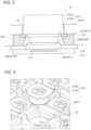
- FIG. 3 is a schematic view showing a structure of the key 21.
- FIG. 3 (similarly to FIG. 9C and FIG. 10A ) shows a cross-section of a pair of second protruding pieces 1A22 in order to show a relation between a flange 212b (to be described later) and the pair of second protruding pieces 1A22 (to be described later).
- the cross-section is a cross-section taken along a line A-A of FIG. 1 .
- the key 21 includes an operation button 212 and a key contact member 211.
- the key contact member 211 is disposed in a device case 1 including an upper case 1A and a lower case 1B.
- the operation button 212 is provided on the key contact member 211, and an upper portion of the operation button 212 protrudes upward from an opening 1C of the device case 1 and is exposed.
- the key contact member 211 includes a dome-shaped bulging portion 215 and a movable contact 216 provided inside the bulging portion 215.
- the bulging portion 215 is connected to a rubber sheet 214 disposed on a circuit board 213 provided below the upper case 1A. In the present embodiment, the bulging portion 215 and the rubber sheet 214 are integrally formed.
- the key contact member 211 is configured to correspond to a plurality of openings 1C (only one opening 1C is shown in FIG. 3 ) provided in the device case 1.
- the bulging portion 215 is connected to a lower portion of the operation button 212 by, for example, a method such as press fitting.
- the movable contact 216 is made of, for example, carbon.
- a fixed contact 217 is provided to face the movable contact 216 on an upper surface of the circuit board 213 so as to be able to come into contact with or separate from the movable contact 216. Accordingly, the key contact member 211 is configured such that when the bulging portion 215 is pressed down by the operation button 212, the bulging portion 215 is elastically deformed and the movable contact 216 comes into contact (makeup) with the fixed contact 217 (see FIG. 9C ), thereby outputting a key input signal.
- the operation button 212 is a synthetic resin member including a main body 212a and a flange 212b extending radially outward at a lower end of the main body 212a.
- the main body 212a has a cylindrical shape, but a shape of the main body 212a is not limited thereto.
- FIG. 4 is a view showing an aspect in which the operation button 212 is inserted into the opening 1C of the upper case 1A (the device case 1).
- the flange 212b has a generally rectangular shape in plan view, and is formed larger than an area of the opening 1C. Accordingly, as shown in FIG. 3 , an upper surface of the flange 212b (a surface on a main body 212a side) comes into contact with a lower surface of an edge portion in the opening 1C of the upper case 1A (a surface facing the rubber sheet 214) so that the flange 212b does not come out of the opening 1C.
- FIG. 5A is a view showing a state where the operation button 212 is inserted into the opening 1C of the upper case 1A in a correct orientation (an orientation).
- FIG. 5B is a view showing a state where the operation button 212 is inserted into the opening 1C of the upper case 1A in a wrong orientation (an orientation other than the above-described orientation).
- FIG. 5C is a view showing a state where the operation button 212 inserted into the opening 1C of the upper case 1A is rotated in a clockwise direction on the sheet.
- the flange 212b of the operation button 212 has a substantially rectangular shape in plan view as described above, and each corner of the lower left and the lower right is cut out. Therefore, a width W1 in a left-right direction of an extension portion (a first extension portion) 212b1 of the flange 212b extending upward on the sheet is larger than a width W2 in the left-right direction of an extension portion (a second extension portion) 212b2 extending downward on the sheet.
- a lower surface of the upper case 1A is provided with a frame portion 1A1 that defines a region R (a region) for receiving the flange 212b.
- the frame portion 1A1 serves as a spacer for providing the key contact member 211 (see FIG. 3 ) with a predetermined interval from the flange 212b.
- the lower surface of the upper case 1A is provided with a guide rib 1A2 that guides the reception of the flange 212b into the region R.
- the guide rib 1A2 is connected to the frame portion 1A1.
- the guide rib 1A2 and the frame portion 1A1 are integrally formed.
- the guide rib 1A2 includes a pair of first protruding pieces 1A21 provided at an upper left corner and an upper right corner of the region R, and a pair of second protruding pieces 1A22 provided at a lower left corner and a lower right corner of the region R.
- the pair of first protruding pieces 1A21 are provided at an interval wider than the width W1 of a first extension portion 212b1, and when the flange 212b is received in the region R, the first protruding pieces 1A21 sandwich the first extension portion 212b1 from lateral sides.
- the pair of second protruding pieces 1A22 are provided at an interval wider than the width W2 of a second extension portion 212b2 and narrower than the width W1 of the first extension portion 212b1, and when the flange 212b is received in the region R, the second protruding pieces 1A22 sandwich the second extension portion 212b2 from lateral sides.
- an interval G1 between a pair of outer surfaces 1A21a (see FIG. 6A ) facing each other of the pair of first protruding pieces 1A21 is larger than the width W1, and an interval G2 between a pair of outer surfaces 1A22a (see FIG.
- a length L3 of the flange 212b in an extending direction is longer than a distance D3 between the first protruding piece 1A21 and the second protruding piece 1A22 and longer than the interval G2.
- a length L4 of a diagonal line of the flange 212b (a straight line passing through a corner portion of the first extension portion 212b1 and a corner portion of the second extension portion 212b2 facing the corner portion of the first extension portion 212b1) is longer than a width D4 of the region R in an up-down direction (an extending direction of the flange 212b).
- the operation button 212 When the operation button 212 is inserted into the opening 1C of the upper case 1A in a wrong orientation (A predetermined orientation other than the correct orientation. For example, an angle of 10 degrees or more and less than 90 degrees, an angle of more than 90 degrees and 170 degrees or less, an angle of 190 degrees or more and less than 270 degrees, or an angle of more than 270 degrees and less than 350 degrees in a clockwise direction with reference to the correct orientation), the first extension portion 212b1 of the flange 212b is designed to have a length that engages (overlaps) with the frame portion 1A1.
- the opening 1C is formed such that, when the operation button 212 is inserted into the opening 1C in a vertically reversed orientation on the sheet of FIG. 5A (that is, when viewed from an insertion direction, the main body 212a is positioned inside the opening 1C and the operation button 212 faces an opposite side to the correct orientation), a part of the extension portion 212b1 overlaps the second protruding piece 1A22.
- the opening 1C is positioned at the center of the region R.
- the operation button 212 when the operation button 212 is inserted into the opening 1C of the upper case 1A in a wrong orientation (for example, a vertically reversed orientation), as shown in FIG. 5B , the first extension portion 212b1 of the flange 212b engages with the pair of second protruding pieces 1A22 (the first extension portion 212b1 of the flange 212b overlaps the second protruding piece 1A22), so that the operation button 212 can be prevented from being inserted (completely inserted) into the opening 1C.
- a wrong orientation for example, a vertically reversed orientation
- completely inserted means that the operation button 212 is inserted to such an extent that the operation button 212 can be used as a product, and does not include a state where only a tip end portion of the main body 212a is positioned inside the opening 1C in the process of insertion.
- the flange 212b does not engage with (does not overlap) the guide rib 1A2.
- the first protruding piece 1A21 is disposed close to the first extension portion 212b1
- the second protruding piece 1A22 is disposed close to the second extension portion 212b2.
- the flange 212b when the second extension portion 212b2 of the flange 212b engages with the pair of second protruding pieces 1A22 (engages with each other in the rotation direction), the flange 212b can be prevented from rotating beyond the above angle.
- the first extension portion 212b1 of the flange 212b may be engaged with the first protruding piece 1A21. Accordingly, the flange 212b can also be prevented from rotating beyond the above angle.
- a length L1 from an outer surface (a surface facing the frame portion 1A1) 1A21b of the first protruding piece 1A21 to a side surface (a surface facing the frame portion 1A1) 212b1b of the first extension portion 212b1 in an extending direction is longer than a distance D1 between a side surface (a surface facing the first protruding piece 1A21) 212b1a of the first extension portion 212b1 and the outer surface 1A21a.
- a length L2 from an outer surface (a surface facing the frame portion 1A1) 1A22b of the second protruding piece 1A22 to a side surface (a surface facing the frame portion 1A1) 212b2b of the second extension portion 212b2 in an extending direction is longer than a distance D2 between a side surface (a surface facing the second protruding piece 1A22) 212b2a of the second extension portion 212b2 and the outer surface 1A22a.
- the flange 212b can be prevented from rotating beyond the above angle.
- FIGS. 6A and 6B only one of the pair of first protruding pieces 1A21 (the same applies to the pair of second protruding pieces 1A22) is shown, but a distance between the extension portions 212b 1 and 212b2 and the other of the first protruding piece 1A21 and the second protruding piece 1A22 is the same as that in FIGS. 6A and 6B .
- FIG. 6A is an enlarged view of the upper left corner of FIG. 5A
- FIG. 6B is an enlarged view of the lower left corner of FIG. 5A .
- the same configuration is applied to the upper right corner of FIG. 5A and the lower right corner of FIG. 5A .
- a distance between one of the extension portions 212b 1 and 212b2 and the guide rib 1A2 is shorter than a distance between the other extension portion of the extension portions 212b1 and 212b2 and the guide rib 1A2.
- one of the lengths L1 and L2 is longer than the other length. Accordingly, the flange 212b can be more reliably prevented from rotating beyond the above angle.
- the length L1 and/or the length L2 may be set to be longer than the distances D1 and D2 by the clearance between the main body 212a and the opening 1C.
- the operation button 212 can be prevented from being erroneously inserted into the opening 1C in addition to a case where the operation button 212 is inserted in the vertically reversed orientation as shown in FIG. 5B .
- FIGS. 7A, 7B , 7D, 7E , 8A, 8B , 8D, and 8E for example, when the operation button 212 is inserted into the opening 1C in a state where the operation button 212 is rotated (rotated clockwise on the sheet) by any angle of 30 degrees, 60 degrees, 120 degrees, 150 degrees, 210 degrees, 240 degrees, 300 degrees, and 330 degrees from a correct orientation (see FIG.
- the length L4 of the diagonal line of the flange 212b is designed to be a predetermined length longer than the width D4 of the region R in the up-down direction (an extending direction of the flange 212b) as described above, so that the operation button 212 can be prevented from being inserted (completely inserted) into the opening 1C by engaging (overlapping) the first extension portion 212b1 of the flange 212b with the frame portion 1A1.
- FIGS. 7C and 8C when the operation button 212 is inserted into the opening 1C in a state where the operation button 212 is rotated by any angle of 90 degrees or 270 degrees from a correct orientation (see FIG.
- the length L3 of the flange 212b in an extending direction is longer than the interval G2 and the width W1 is longer than the distance D3, so that the operation button 212 can be prevented from being inserted (completely inserted) into the opening 1C by engaging (overlapping) the first extension portion 212b1 of the flange 212b with the pair of second protruding pieces 1A22.
- the opening 1C is formed such that, when the operation button 212 is inserted into the opening 1C in a state where the operation button 212 is rotated by any angle of 90 degrees or 270 degrees from a correct orientation (that is, when viewed from an insertion direction, the main body 212a is positioned inside the opening 1C and the operation button 212 is rotated by any angle of 90 degrees or 270 degrees from the correct orientation), at least a part of the second extension portion 212b1 overlaps the second protruding piece 1A22.
- the flange 212b when the second extension portion 212b2 of the flange 212b engages with the pair of second protruding pieces 1A22, the flange 212b can be prevented from rotating beyond the above angle.
- the first extension portion 212b1 of the flange 212b is engaged with the pair of first protruding pieces 1A21, the flange 212b can also be prevented from rotating beyond the above angle.
- a guide rib of the related art has such a shape that an outer surface (an outer surface facing the flange 212b with a gap therebetween) that can come into contact with the flange 212b is perpendicular to a lower surface of the upper case 1A, when an end of the operation button 212 is pressed to be in a so-called obliquely pressed state, as shown in FIG.
- At least a part of the pair of first protruding pieces 1A21 and the pair of second protruding pieces 1A22 is configured such that an interval between the flange 212b and the pair of first protruding pieces 1A21 and the pair of second protruding pieces 1A22 is widened when a pressing operation is performed toward a pressing direction of the operation button 212.
- outer surfaces that is, outer surfaces facing the flange 212b, specifically, outer surfaces 1A21a disposed close to and facing the flange 212b (with an interval therebetween)
- outer surfaces that is, outer surfaces facing the flange 212b, specifically, outer surfaces 1A22a disposed close to and facing the flange 212b (with a gap therebetween)
- outer surfaces that can come into contact with the flange 212b of the pair of second protruding pieces 1A22 are provided with a gradient that moves away from the flange 212b toward the pressing direction of the operation button 212.
- a taper for example, a taper angle; 8 to 10°
- the operation button 212 is less likely to interfere with the inner surface of the opening 1C. Therefore, it is possible to more effectively prevent occurrence of a failure in which the operation button 212 is not fully pressed or a failure in which the operation button 212 cannot be restored.
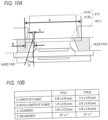
- a size of the flange 212b of the operation button 212 is made different between an upper half key group (type I; small key) and a lower half key group (type II; large key) of the input key group 2, and the gradient of the guide rib 1A2 is made different.
- type I small key
- type II large key
- a length (A) of the flange 212b is 8.95 ⁇ 0.05 (mm)
- a notch length (B) of the flange 212b is 1.47 ⁇ 0.05 (mm)
- a clearance (C) between the flange 212b and the guide rib 1A2 is 0.20 ⁇ 0.20 (mm)
- the above-described gradient (D) of the guide rib 1A2 is 20° ⁇ 1°.
- a length (A) of the flange 212b is 11.00 ⁇ 0.05 (mm)
- a notch length (B) of the flange 212b is 2.05 ⁇ 0.05 (mm)
- a clearance (C) between the flange 212b and the guide rib 1A2 is 0.20 ⁇ 0.20 (mm)
- the above-described gradient (D) of the guide rib 1A2 is 10° ⁇ 1°. That is, the key group of type II (the second operation button) whose length (A) of the flange 212b is longer than that of type I is designed to have the smaller gradient (D) of the guide rib 1A2. This is because an inclination of the operation button 212 when the key having the longer length (A) of the flange 212b presses the end of the operation button 212 is small.
- the scientific electronic calculator 100 includes the operation button 212 having the flange 212b and the device case 1 formed with the opening 1C into which the operation button 212 is inserted.
- the device case 1 is provided with a restricting portion (the frame portion 1A1 and the guide rib 1A2) that does not overlap the flange 212b when the operation button 212 is inserted into the opening 1C in a correct orientation (an orientation) and that overlaps the flange 212b when the operation button 212 is to be inserted into the opening 1C in an orientation other than the correct orientation.
- the operation button 212 when the operation button 212 is to be inserted into the opening 1C in an orientation other than the correct orientation, that is, when the operation button 212 is to be inserted into the opening 1C in a wrong orientation, the operation button 212 can be prevented from being inserted (completely inserted) into the opening 1C by engaging (overlapping) the flange 212b with the restricting portion (the frame portion 1A1 and the guide rib 1A2), so that the operation button 212 can be prevented from being assembled to the device case 1 in a wrong orientation.
- the device case 1 of the scientific electronic calculator 100 is provided with, as the restricting portion, the guide rib 1A2 that guides the reception of the flange 212b into the region R of the device case 1 when the operation button 212 is inserted into the opening 1C. Therefore, since the guide rib 1A2 can guide the reception of the flange 212b into the region R of the device case 1, and can function as the restricting portion, the operation button 212 can be suitably prevented from being inserted into the opening 1C without complicating a structure in the device case 1.
- the flange 212b includes the first extension portion 212b1 extending in one direction of upper, lower, left, and right directions and the second extension portion 212b2 extending in a direction opposite to the one direction.
- the width W1 of the first extension portion 212b1 in a direction orthogonal to the extending direction is larger than the width W2 of the second extension portion 212b2,
- the guide rib 1A2 includes the pair of first protruding pieces 1A21 provided at an interval wider than the width W1 of the first extension portion 212b 1, and the pair of second protruding pieces 1A22 provided at an interval wider than the width W2 of the second extension portion 212b2 and narrower than the width W1 of the first extension portion 212b 1,
- the pair of first protruding pieces 1A21 are provided at positions where the first extension portion 212b 1 is sandwiched from lateral sides when the flange 212b is received in the region R
- the pair of second protruding pieces 1A22 are provided at positions where the second extension portion 212b2 is sandwiched from lateral sides when the flange 212b is received in the region R.
- the operation button 212 when the operation button 212 is to be inserted into the opening 1C of the device case 1 in a vertically reversed orientation to the correct orientation, the operation button 212 can be prevented from being inserted (completely inserted) into the opening 1C by engaging the first extension portion 212b1 of the flange 212b with the pair of second protruding pieces 1A22 from the relation between the flange 212b and the guide rib 1A2 described above.
- the device case 1 of the scientific electronic calculator 100 is provided with, as the restricting portion, the frame portion 1A1 that defines the region R.
- the frame portion 1A1 that defines the region R.
- the operation button 212 when the operation button 212 is inserted into the opening 1C in a wrong orientation other than the vertically reversed orientation, the operation button 212 can be prevented from being inserted (completely inserted) into the opening 1C by engaging (overlapping) the flange 212b with the frame portion 1A1 from the relation between the flange 212b and the frame portion 1A1 described above, so that the operation button 212 can be more effectively prevented from being assembled to the device case 1 in a wrong orientation.
- the guide rib 1A2 is engaged with the flange 212b when the operation button 212 is rotated to an angle to prevent the operation button 212 from rotating beyond the above angle. Therefore, the guide rib 1A2 prevents the operation button 212 from rotating beyond an angle, so that the backlash of the operation button 212 can be prevented.
- the width W1 in the left-right direction of the extension portion (the first extension portion) 212b1 that extends upward on the sheet is set larger than a width W2 in the left-right direction of the extension portion (the second extension portion) 212b2 that extends downward on the sheet.
- the width W1 of the extension portion (the first extension portion) 212b 1 that extends upward on the sheet may be smaller than the width W2 of the extension portion (the second extension portion) 212b2 that extends downward on the sheet.
- the extension portion extends in the up-down direction.
- the extension portion may extend in the left-right direction instead of the up-down direction.
- the outer surfaces 1A21a that can come into contact with the flange 212b of the pair of first protruding pieces 1A21 and the outer surfaces 1A22a that can come into contact with the flange 212b of the pair of second protruding pieces 1A22 are provided with a gradient that moves away from the flange 212b toward the pressing direction of the operation button 212.
- the gradient is not limited to a case where the gradient is formed from an upper end to a lower end of each outer surface (from one end to the other end in the thickness direction of the device case 1).
- the gradient may be provided between the upper end of each of the outer surfaces 1A21a and 1A22a (a base end of the lower surface of the upper case 1A) and a predetermined height (for example, a height corresponding to a thickness of the flange 212b).
- At least a part of the first protruding piece 1A21 of any one of the pair of first protruding pieces 1A21 and at least a part of the second protruding piece 1A22 of any one of the pair of second protruding pieces 1A22 may be configured such that an interval between the flange 212b and the first protruding piece 1A21 or the second protruding piece 1A22 is widened when a pressing operation is performed toward the pressing direction of the operation button 212.
- the present invention can be applied to an electronic device capable of preventing an operation button from being assembled to a housing in a wrong orientation, and a method for manufacturing an electronic device.
Landscapes
- Engineering & Computer Science (AREA)
- Physics & Mathematics (AREA)
- General Physics & Mathematics (AREA)
- Automation & Control Theory (AREA)
- Push-Button Switches (AREA)
- Manufacture Of Switches (AREA)
- Mechanisms For Operating Contacts (AREA)
- Input From Keyboards Or The Like (AREA)
- Microelectronics & Electronic Packaging (AREA)
Abstract
Description
- The present invention relates to an electronic device and a method for manufacturing an electronic device.
- In the related art, an electronic desktop computer (calculator) is widely used for simple calculation. In particular, in the electronic desktop computer, a key arrangement is determined and a key touch is devised so that a quick and accurate input operation can be performed in office applications such as performing a large number of calculations (see, for example, Patent Literature 1).
- Patent Literature 1:
JPH05-128938A - In a key switch disclosed in
Patent Literature 1, a leg portion is provided to protrude around a keytop. The leg portion prevents the keytop from protruding from the housing by engagement with a peripheral portion of an opening of the housing. Since the leg portions are provided to protrude at four positions in a vertically and horizontally symmetrical manner, the keytop may be assembled upside down when the keytop is assembled to the housing. - The present invention has been made in view of the above circumstances, and an object thereof is to prevent an operation button from being assembled to a housing in a wrong orientation.
- In order to achieve the above problem, an electronic device according to the present invention includes:
- an operation button having a flange; and
- a device case formed with an opening into which the operation button is inserted, in which
- the device case is provided with a restricting portion that does not overlap the flange when the operation button is inserted into the opening in an orientation, and that overlaps the flange when the operation button is to be inserted into the opening in an orientation other than the orientation.
- According to the present invention, it is possible to prevent an operation button from being assembled to a housing in a wrong orientation.
-
- [
FIG. 1] FIG. 1 is a perspective view showing an overview of a scientific electronic calculator as an example of an electronic device. - [
FIG. 2] FIG. 2 is a block diagram showing a functional configuration of a scientific electronic calculator. - [
FIG. 3] FIG. 3 is a schematic view showing a structure of a key. - [
FIG. 4] FIG. 4 is a view showing an aspect in which an operation button is inserted into an opening of an upper case (device case). - [
FIG. 5A] FIG. 5A is a view showing a state where an operation button is inserted into the opening of the upper case in a correct orientation. - [
FIG. 5B] FIG. 5B is a view showing a state where an operation button is to be inserted into the opening of the upper case in a wrong orientation. - [
FIG. 5C] FIG. 5C is a view showing a state where an operation button inserted into the opening of the upper case is rotated in a clockwise direction in the drawing. - [
FIG. 6A] FIG. 6A is an enlarged view of an upper left corner ofFIG. 5A . - [
FIG. 6B] FIG. 6B is an enlarged view of a lower left corner ofFIG. 5A . - [
FIG. 7A] FIG. 7A is a view showing a state where an operation button is inserted into the opening of the upper case in a wrong orientation. - [
FIG. 7B] FIG. 7B is a view showing a state where an operation button is inserted into the opening of the upper case in a wrong orientation. - [
FIG. 7C] FIG. 7C is a view showing a state where an operation button is inserted into the opening of the upper case in a wrong orientation. - [
FIG. 7D] FIG. 7D is a view showing a state where an operation button is inserted into the opening of the upper case in a wrong orientation. - [
FIG. 7E] FIG. 7E is a view showing a state where an operation button is inserted into the opening of the upper case in a wrong orientation. - [
FIG. 8A] FIG. 8A is a view showing a state where an operation button is inserted into the opening of the upper case in a wrong orientation. - [
FIG. 8B] FIG. 8B is a view showing a state where an operation button is inserted into the opening of the upper case in a wrong orientation. - [
FIG. 8C] FIG. 8C is a view showing a state where an operation button is inserted into the opening of the upper case in a wrong orientation. - [
FIG. 8D] FIG. 8D is a view showing a state where an operation button is inserted into the opening of the upper case in a wrong orientation. - [
FIG. 8E] FIG. 8E is a view showing a state where an operation button is inserted into the opening of the upper case in a wrong orientation. - [
FIG. 9A] FIG. 9A is a view illustrating a guide rib of the related art. - [
FIG. 9B] FIG. 9B is a view showing a state of an operation button when a pressing operation of an end of the operation button is performed in a case where the guide rib of the related art is provided. - [
FIG. 9C] FIG. 9C is a view showing a state of an operation button when a pressing operation of an end of the operation button is performed in a case where a guide rib according to the present embodiment is provided. - [
FIG. 10A] FIG. 10A is a view showing measurement points of various dimensions for a flange and a guide rib. - [
FIG. 10B] FIG. 10B is a table showing the correspondence of the various dimensions between a key group of type I and a key group of type II. - Hereinafter, an embodiment of an electronic device according to the present invention will be described with reference to the drawings. Hereinafter, a case where the electronic device is a scientific electronic calculator will be described, but the present invention is not limited to a case where the electronic device is a scientific electronic calculator, and is applied to any electronic device as long as the electronic device is an electronic device including an operation button that is inserted into an opening of a device case so as to be pressed.
-
FIG. 1 is a perspective view of a scientific electronic calculator as an example of an electronic device according to the present embodiment. As shown inFIG. 1 , a scientificelectronic calculator 100 includes adisplay 10 and an inputkey group 2 including various key groups. - The input
key group 2 is a key group for receiving an input operation of a mathematical expression component such as a numerical value, a calculation symbol, or the like from a user or receiving instruction operations of various processes, and includes a plurality of keys (a numeric key, a cursor key, an AC key, a CODE key, a SHIFT key, and the like) to which specific functions are assigned. - The
display 10 is, for example, a liquid crystal display (LCD), and is a display unit that displays various data such as characters, codes, symbols, mathematical expressions, calculation results, and tables (referred to as mathematical expressions, tables, and the like) corresponding to operations of the inputkey group 2 and the like on a plurality of dots. - Next, a functional configuration of the scientific
electronic calculator 100 will be described.FIG. 2 is a block diagram showing the functional configuration of the scientificelectronic calculator 100. As shown inFIG. 2 , the scientificelectronic calculator 100 includes a central processing unit (CPU) 11, adisplay driving unit 12, akey input unit 13, and astorage unit 14. Although not shown, the scientificelectronic calculator 100 appropriately includes, for example, a random access memory (RAM) that temporarily stores data such as mathematical expressions and tables displayed on thedisplay 10. - The
display driving unit 12 performs driving control to display various kinds of information on thedisplay 10 under the control of theCPU 11. Thedisplay driving unit 12 adjusts a contrast ratio when displaying on thedisplay 10. - The
key input unit 13 includes the above-described inputkey group 2, and outputs, to theCPU 11, a key input signal corresponding to a key input by a user operation. Then, theCPU 11 receives a key input signal corresponding to a key input by a user operation, displays a corresponding mathematical expression, table, or the like on thedisplay 10, executes calculation, or performs various processes. - The
storage unit 14 is a memory that stores programs and the like. In the present embodiment, thestorage unit 14 includes various storage areas, and includes a storage area for storing programs for theCPU 11 to execute various functions of the scientificelectronic calculator 100 and data necessary for executing the programs. - The
CPU 11 centrally controls each unit of the scientificelectronic calculator 100. Specifically, theCPU 11 reads a program specified from the system program and the various application programs stored in the storage area of thestorage unit 14, develops the program in the work area of thestorage unit 14, and executes various processes in cooperation with the program developed in thestorage unit 14. TheCPU 11 controls thedisplay driving unit 12 to perform necessary display on thedisplay 10. - Next, a structure of each of the keys constituting the input
key group 2 will be described by using, as a representative example, a key 21 shown inFIG. 1 .FIG. 3 is a schematic view showing a structure of the key 21.FIG. 3 (similarly toFIG. 9C andFIG. 10A ) shows a cross-section of a pair of second protruding pieces 1A22 in order to show a relation between aflange 212b (to be described later) and the pair of second protruding pieces 1A22 (to be described later). The cross-section is a cross-section taken along a line A-A ofFIG. 1 . - As shown in
FIG. 3 , the key 21 includes anoperation button 212 and akey contact member 211. Thekey contact member 211 is disposed in adevice case 1 including anupper case 1A and alower case 1B. Theoperation button 212 is provided on thekey contact member 211, and an upper portion of theoperation button 212 protrudes upward from anopening 1C of thedevice case 1 and is exposed. Thekey contact member 211 includes a dome-shaped bulgingportion 215 and amovable contact 216 provided inside the bulgingportion 215. The bulgingportion 215 is connected to arubber sheet 214 disposed on acircuit board 213 provided below theupper case 1A. In the present embodiment, the bulgingportion 215 and therubber sheet 214 are integrally formed. Thekey contact member 211 is configured to correspond to a plurality ofopenings 1C (only one opening 1C is shown inFIG. 3 ) provided in thedevice case 1. The bulgingportion 215 is connected to a lower portion of theoperation button 212 by, for example, a method such as press fitting. Themovable contact 216 is made of, for example, carbon. - A
fixed contact 217 is provided to face themovable contact 216 on an upper surface of thecircuit board 213 so as to be able to come into contact with or separate from themovable contact 216. Accordingly, thekey contact member 211 is configured such that when the bulgingportion 215 is pressed down by theoperation button 212, the bulgingportion 215 is elastically deformed and themovable contact 216 comes into contact (makeup) with the fixed contact 217 (seeFIG. 9C ), thereby outputting a key input signal. - As shown in
FIGS. 3 and 4 , theoperation button 212 is a synthetic resin member including amain body 212a and aflange 212b extending radially outward at a lower end of themain body 212a. In the present embodiment, themain body 212a has a cylindrical shape, but a shape of themain body 212a is not limited thereto. Here,FIG. 4 is a view showing an aspect in which theoperation button 212 is inserted into theopening 1C of theupper case 1A (the device case 1). - As shown in
FIGS. 4 ,5A, 5B, and 5C , theflange 212b has a generally rectangular shape in plan view, and is formed larger than an area of theopening 1C. Accordingly, as shown inFIG. 3 , an upper surface of theflange 212b (a surface on amain body 212a side) comes into contact with a lower surface of an edge portion in theopening 1C of theupper case 1A (a surface facing the rubber sheet 214) so that theflange 212b does not come out of theopening 1C. - Next, a shape of the
flange 212b will be described in detail with reference toFIGS. 5A, 5B, and 5C. FIG. 5A is a view showing a state where theoperation button 212 is inserted into theopening 1C of theupper case 1A in a correct orientation (an orientation).FIG. 5B is a view showing a state where theoperation button 212 is inserted into theopening 1C of theupper case 1A in a wrong orientation (an orientation other than the above-described orientation).FIG. 5C is a view showing a state where theoperation button 212 inserted into theopening 1C of theupper case 1A is rotated in a clockwise direction on the sheet. - As shown in
FIG. 5A , theflange 212b of theoperation button 212 has a substantially rectangular shape in plan view as described above, and each corner of the lower left and the lower right is cut out. Therefore, a width W1 in a left-right direction of an extension portion (a first extension portion) 212b1 of theflange 212b extending upward on the sheet is larger than a width W2 in the left-right direction of an extension portion (a second extension portion) 212b2 extending downward on the sheet. - On the other hand, as shown in
FIG. 5A , a lower surface of theupper case 1A is provided with a frame portion 1A1 that defines a region R (a region) for receiving theflange 212b. Here, the frame portion 1A1 serves as a spacer for providing the key contact member 211 (seeFIG. 3 ) with a predetermined interval from theflange 212b. The lower surface of theupper case 1A is provided with a guide rib 1A2 that guides the reception of theflange 212b into the region R. The guide rib 1A2 is connected to the frame portion 1A1. In the present embodiment, the guide rib 1A2 and the frame portion 1A1 are integrally formed. - As shown in
FIG. 5A , the guide rib 1A2 includes a pair of first protruding pieces 1A21 provided at an upper left corner and an upper right corner of the region R, and a pair of second protruding pieces 1A22 provided at a lower left corner and a lower right corner of the region R. The pair of first protruding pieces 1A21 are provided at an interval wider than the width W1 of a first extension portion 212b1, and when theflange 212b is received in the region R, the first protruding pieces 1A21 sandwich the first extension portion 212b1 from lateral sides. In addition, the pair of second protruding pieces 1A22 are provided at an interval wider than the width W2 of a second extension portion 212b2 and narrower than the width W1 of the first extension portion 212b1, and when theflange 212b is received in the region R, the second protruding pieces 1A22 sandwich the second extension portion 212b2 from lateral sides. In other words, an interval G1 between a pair of outer surfaces 1A21a (seeFIG. 6A ) facing each other of the pair of first protruding pieces 1A21 is larger than the width W1, and an interval G2 between a pair of outer surfaces 1A22a (seeFIG. 6B ) facing each other of the pair of second protruding pieces 1A22 is larger than the width W2 and smaller than the width W1. InFIG. 5A , although the intervals G1 and G2 are shown at base ends of the outer surfaces 1A21a and 1A22a, the interval G1 is larger than the width W1 and the interval G2 is larger than the width W2 and smaller than the width W1 at any position of the pair of outer surfaces 1A21a and 1A22a. - A length L3 of the
flange 212b in an extending direction (a direction orthogonal to the widths W1 and W2) is longer than a distance D3 between the first protruding piece 1A21 and the second protruding piece 1A22 and longer than the interval G2. A length L4 of a diagonal line of theflange 212b (a straight line passing through a corner portion of the first extension portion 212b1 and a corner portion of the second extension portion 212b2 facing the corner portion of the first extension portion 212b1) is longer than a width D4 of the region R in an up-down direction (an extending direction of theflange 212b). When theoperation button 212 is inserted into theopening 1C of theupper case 1A in a wrong orientation (A predetermined orientation other than the correct orientation. For example, an angle of 10 degrees or more and less than 90 degrees, an angle of more than 90 degrees and 170 degrees or less, an angle of 190 degrees or more and less than 270 degrees, or an angle of more than 270 degrees and less than 350 degrees in a clockwise direction with reference to the correct orientation), the first extension portion 212b1 of theflange 212b is designed to have a length that engages (overlaps) with the frame portion 1A1. - More specifically, the opening 1C is formed such that, when the
operation button 212 is inserted into the opening 1C in a vertically reversed orientation on the sheet ofFIG. 5A (that is, when viewed from an insertion direction, themain body 212a is positioned inside the opening 1C and theoperation button 212 faces an opposite side to the correct orientation), a part of the extension portion 212b1 overlaps the second protruding piece 1A22. In the present embodiment, the opening 1C is positioned at the center of the region R. - Accordingly, when the
operation button 212 is inserted into theopening 1C of theupper case 1A in a wrong orientation (for example, a vertically reversed orientation), as shown inFIG. 5B , the first extension portion 212b1 of theflange 212b engages with the pair of second protruding pieces 1A22 (the first extension portion 212b1 of theflange 212b overlaps the second protruding piece 1A22), so that theoperation button 212 can be prevented from being inserted (completely inserted) into theopening 1C. In the present specification, "completely inserted" means that theoperation button 212 is inserted to such an extent that theoperation button 212 can be used as a product, and does not include a state where only a tip end portion of themain body 212a is positioned inside the opening 1C in the process of insertion. On the other hand, as shown inFIG. 5A , when theoperation button 212 is inserted into theopening 1C of theupper case 1A in a correct orientation, theflange 212b does not engage with (does not overlap) the guide rib 1A2. - In the present embodiment, the first protruding piece 1A21 is disposed close to the first extension portion 212b1, and the second protruding piece 1A22 is disposed close to the second extension portion 212b2. When the
operation button 212 correctly inserted into theopening 1C of theupper case 1A is rotated to an angle, as shown inFIG. 5C , theflange 212b engages with the guide rib 1A2 (engages with each other in a rotation direction), so that theflange 212b can be prevented from rotating beyond the above angle. In the present embodiment, when the second extension portion 212b2 of theflange 212b engages with the pair of second protruding pieces 1A22 (engages with each other in the rotation direction), theflange 212b can be prevented from rotating beyond the above angle. In addition, depending on a clearance between themain body 212a and theopening 1C and a manufacturing error, the first extension portion 212b1 of theflange 212b may be engaged with the first protruding piece 1A21. Accordingly, theflange 212b can also be prevented from rotating beyond the above angle. - Specifically, as shown in
FIG. 6A , in a state where theoperation button 212 is inserted in a correct orientation, a length L1 from an outer surface (a surface facing the frame portion 1A1) 1A21b of the first protruding piece 1A21 to a side surface (a surface facing the frame portion 1A1) 212b1b of the first extension portion 212b1 in an extending direction is longer than a distance D1 between a side surface (a surface facing the first protruding piece 1A21) 212b1a of the first extension portion 212b1 and the outer surface 1A21a. Similarly, as shown inFIG. 6B , in a state where theoperation button 212 is inserted in a correct orientation, a length L2 from an outer surface (a surface facing the frame portion 1A1) 1A22b of the second protruding piece 1A22 to a side surface (a surface facing the frame portion 1A1) 212b2b of the second extension portion 212b2 in an extending direction is longer than a distance D2 between a side surface (a surface facing the second protruding piece 1A22) 212b2a of the second extension portion 212b2 and the outer surface 1A22a. According to such a structure, theflange 212b can be prevented from rotating beyond the above angle. InFIGS. 6A and 6B , only one of the pair of first protruding pieces 1A21 (the same applies to the pair of second protruding pieces 1A22) is shown, but a distance between theextension portions 212bFIGS. 6A and 6B . Here,FIG. 6A is an enlarged view of the upper left corner ofFIG. 5A , andFIG. 6B is an enlarged view of the lower left corner ofFIG. 5A . The same configuration is applied to the upper right corner ofFIG. 5A and the lower right corner ofFIG. 5A . - More specifically, when the operation button is deviated in either a left or right direction on the sheet of
FIG. 5A , a distance between one of theextension portions 212bflange 212b can be more reliably prevented from rotating beyond the above angle. In one embodiment, the length L1 and/or the length L2 may be set to be longer than the distances D1 and D2 by the clearance between themain body 212a and theopening 1C. - In the present embodiment, since the lower surface of the
upper case 1A is provided with the frame portion 1A1 and the guide rib 1A2 (the pair of first protruding pieces 1A21 and the pair of second protruding pieces 1A22), theoperation button 212 can be prevented from being erroneously inserted into the opening 1C in addition to a case where theoperation button 212 is inserted in the vertically reversed orientation as shown inFIG. 5B . - Specifically, as shown in
FIGS. 7A, 7B ,7D, 7E ,8A, 8B ,8D, and 8E , for example, when theoperation button 212 is inserted into the opening 1C in a state where theoperation button 212 is rotated (rotated clockwise on the sheet) by any angle of 30 degrees, 60 degrees, 120 degrees, 150 degrees, 210 degrees, 240 degrees, 300 degrees, and 330 degrees from a correct orientation (seeFIG. 5A ), the length L4 of the diagonal line of theflange 212b is designed to be a predetermined length longer than the width D4 of the region R in the up-down direction (an extending direction of theflange 212b) as described above, so that theoperation button 212 can be prevented from being inserted (completely inserted) into the opening 1C by engaging (overlapping) the first extension portion 212b1 of theflange 212b with the frame portion 1A1. As shown inFIGS. 7C and8C , when theoperation button 212 is inserted into the opening 1C in a state where theoperation button 212 is rotated by any angle of 90 degrees or 270 degrees from a correct orientation (seeFIG. 5A ), the length L3 of theflange 212b in an extending direction (a direction orthogonal to the widths W1 and W2) is longer than the interval G2 and the width W1 is longer than the distance D3, so that theoperation button 212 can be prevented from being inserted (completely inserted) into the opening 1C by engaging (overlapping) the first extension portion 212b1 of theflange 212b with the pair of second protruding pieces 1A22. More specifically, the opening 1C is formed such that, when theoperation button 212 is inserted into the opening 1C in a state where theoperation button 212 is rotated by any angle of 90 degrees or 270 degrees from a correct orientation (that is, when viewed from an insertion direction, themain body 212a is positioned inside the opening 1C and theoperation button 212 is rotated by any angle of 90 degrees or 270 degrees from the correct orientation), at least a part of the second extension portion 212b1 overlaps the second protruding piece 1A22. - In the present embodiment, as described with reference to
FIG. 5C , when the second extension portion 212b2 of theflange 212b engages with the pair of second protruding pieces 1A22, theflange 212b can be prevented from rotating beyond the above angle. When the first extension portion 212b1 of theflange 212b is engaged with the pair of first protruding pieces 1A21, theflange 212b can also be prevented from rotating beyond the above angle. Therefore, by making the widths W1 and W2 of the first extension portion 212b1 and the second extension portion 212b2 as large as possible, that is, by making a clearance (gap) between the first extension portion 212b1 and the pair of first protruding pieces 1A21 or a clearance (gap) between the second extension portion 212b2 and the pair of second protruding pieces 1A22 as small as possible, a backlash of theoperation button 212 can be further prevented. - However, as shown in
FIG. 9A , since a guide rib of the related art has such a shape that an outer surface (an outer surface facing theflange 212b with a gap therebetween) that can come into contact with theflange 212b is perpendicular to a lower surface of theupper case 1A, when an end of theoperation button 212 is pressed to be in a so-called obliquely pressed state, as shown inFIG. 9B , a failure in which the first extension portion 212b1 and/or the second extension portion 212b2 (theflange 212b) interferes with the guide rib and themovable contact 216 does not come into contact with (makeup) the fixedcontact 217 or a failure in which theoperation button 212 is not restored occurs. - Here, in the present embodiment, as shown in
FIGS. 3 and 4 , at least a part of the pair of first protruding pieces 1A21 and the pair of second protruding pieces 1A22 is configured such that an interval between theflange 212b and the pair of first protruding pieces 1A21 and the pair of second protruding pieces 1A22 is widened when a pressing operation is performed toward a pressing direction of theoperation button 212. Specifically, outer surfaces (that is, outer surfaces facing theflange 212b, specifically, outer surfaces 1A21a disposed close to and facing theflange 212b (with an interval therebetween)) that can come into contact with theflange 212b of the pair of first protruding pieces 1A21, and outer surfaces (that is, outer surfaces facing theflange 212b, specifically, outer surfaces 1A22a disposed close to and facing theflange 212b (with a gap therebetween)) that can come into contact with theflange 212b of the pair of second protruding pieces 1A22 are provided with a gradient that moves away from theflange 212b toward the pressing direction of theoperation button 212. Accordingly, even when the end of theoperation button 212 is pressed to be in a so-called obliquely pressed state, as shown inFIG. 9C , it is possible to prevent theflange 212b (the second extension portion 212b2) from interfering with the guide rib 1A2 (the pair of second protruding pieces 1A22). As a result, it is possible to prevent occurrence of a failure in which themovable contact 216 does not come into contact (makeup) with the fixedcontact 217 or a failure in which theoperation button 212 is not restored. In the present embodiment, a taper (for example, a taper angle; 8 to 10°) widening toward the pressing direction of theoperation button 212 is provided on an inner surface of theopening 1C. Accordingly, even when the end of theoperation button 212 is pressed to be in a so-called obliquely pressed state, theoperation button 212 is less likely to interfere with the inner surface of theopening 1C. Therefore, it is possible to more effectively prevent occurrence of a failure in which theoperation button 212 is not fully pressed or a failure in which theoperation button 212 cannot be restored. - Further, in the present embodiment, as shown in
FIG. 1 , a size of theflange 212b of theoperation button 212 is made different between an upper half key group (type I; small key) and a lower half key group (type II; large key) of the inputkey group 2, and the gradient of the guide rib 1A2 is made different. Specifically, as shown inFIGS. 10A and 10B , for a key group of type I (a first operation button), a length (A) of theflange 212b is 8.95 ± 0.05 (mm), a notch length (B) of theflange 212b is 1.47 ± 0.05 (mm), a clearance (C) between theflange 212b and the guide rib 1A2 is 0.20 ± 0.20 (mm), and the above-described gradient (D) of the guide rib 1A2 is 20° ± 1°. On the other hand, for a key group of type II (a second operation button), a length (A) of theflange 212b is 11.00 ± 0.05 (mm), a notch length (B) of theflange 212b is 2.05 ± 0.05 (mm), a clearance (C) between theflange 212b and the guide rib 1A2 is 0.20 ± 0.20 (mm), and the above-described gradient (D) of the guide rib 1A2 is 10° ± 1°. That is, the key group of type II (the second operation button) whose length (A) of theflange 212b is longer than that of type I is designed to have the smaller gradient (D) of the guide rib 1A2. This is because an inclination of theoperation button 212 when the key having the longer length (A) of theflange 212b presses the end of theoperation button 212 is small. - As described above, the scientific
electronic calculator 100 according to the present embodiment includes theoperation button 212 having theflange 212b and thedevice case 1 formed with the opening 1C into which theoperation button 212 is inserted. Thedevice case 1 is provided with a restricting portion (the frame portion 1A1 and the guide rib 1A2) that does not overlap theflange 212b when theoperation button 212 is inserted into the opening 1C in a correct orientation (an orientation) and that overlaps theflange 212b when theoperation button 212 is to be inserted into the opening 1C in an orientation other than the correct orientation. Accordingly, when theoperation button 212 is to be inserted into the opening 1C in an orientation other than the correct orientation, that is, when theoperation button 212 is to be inserted into the opening 1C in a wrong orientation, theoperation button 212 can be prevented from being inserted (completely inserted) into the opening 1C by engaging (overlapping) theflange 212b with the restricting portion (the frame portion 1A1 and the guide rib 1A2), so that theoperation button 212 can be prevented from being assembled to thedevice case 1 in a wrong orientation. - The
device case 1 of the scientificelectronic calculator 100 according to the present embodiment is provided with, as the restricting portion, the guide rib 1A2 that guides the reception of theflange 212b into the region R of thedevice case 1 when theoperation button 212 is inserted into theopening 1C. Therefore, since the guide rib 1A2 can guide the reception of theflange 212b into the region R of thedevice case 1, and can function as the restricting portion, theoperation button 212 can be suitably prevented from being inserted into the opening 1C without complicating a structure in thedevice case 1. - In the scientific
electronic calculator 100 according to the present embodiment, theflange 212b includes the first extension portion 212b1 extending in one direction of upper, lower, left, and right directions and the second extension portion 212b2 extending in a direction opposite to the one direction. The width W1 of the first extension portion 212b1 in a direction orthogonal to the extending direction is larger than the width W2 of the second extension portion 212b2, the guide rib 1A2 includes the pair of first protruding pieces 1A21 provided at an interval wider than the width W1 of thefirst 1, and the pair of second protruding pieces 1A22 provided at an interval wider than the width W2 of the second extension portion 212b2 and narrower than the width W1 of theextension portion 212bfirst 1, the pair of first protruding pieces 1A21 are provided at positions where theextension portion 212bfirst 1 is sandwiched from lateral sides when theextension portion 212bflange 212b is received in the region R, and the pair of second protruding pieces 1A22 are provided at positions where the second extension portion 212b2 is sandwiched from lateral sides when theflange 212b is received in the region R. Accordingly, when theoperation button 212 is to be inserted into theopening 1C of thedevice case 1 in a vertically reversed orientation to the correct orientation, theoperation button 212 can be prevented from being inserted (completely inserted) into the opening 1C by engaging the first extension portion 212b1 of theflange 212b with the pair of second protruding pieces 1A22 from the relation between theflange 212b and the guide rib 1A2 described above. - Further, the
device case 1 of the scientificelectronic calculator 100 according to the present embodiment is provided with, as the restricting portion, the frame portion 1A1 that defines the region R. When theoperation button 212 is inserted into the opening 1C in a correct orientation (an orientation), the frame portion 1A1 does not engage with (does not overlap) theflange 212b, and when theoperation button 212 is inserted into the opening 1C in a wrong orientation (a predetermined orientation other than the orientation), the frame portion 1A1 engages with (overlaps) theflange 212b. Accordingly, when theoperation button 212 is inserted into the opening 1C in a wrong orientation other than the vertically reversed orientation, theoperation button 212 can be prevented from being inserted (completely inserted) into the opening 1C by engaging (overlapping) theflange 212b with the frame portion 1A1 from the relation between theflange 212b and the frame portion 1A1 described above, so that theoperation button 212 can be more effectively prevented from being assembled to thedevice case 1 in a wrong orientation. - In addition, in the scientific
electronic calculator 100 according to the present embodiment, the guide rib 1A2 is engaged with theflange 212b when theoperation button 212 is rotated to an angle to prevent theoperation button 212 from rotating beyond the above angle. Therefore, the guide rib 1A2 prevents theoperation button 212 from rotating beyond an angle, so that the backlash of theoperation button 212 can be prevented. - Although the embodiment of the present invention has been described above, the present invention is not limited to the embodiment, and various modifications can be made without departing from the gist thereof.
- In the above embodiment, as shown in
FIG. 5A , in theflange 212b of theoperation button 212, the width W1 in the left-right direction of the extension portion (the first extension portion) 212b1 that extends upward on the sheet is set larger than a width W2 in the left-right direction of the extension portion (the second extension portion) 212b2 that extends downward on the sheet. Alternatively, for example, the width W1 of the extension portion (the first extension portion)212b 1 that extends upward on the sheet may be smaller than the width W2 of the extension portion (the second extension portion) 212b2 that extends downward on the sheet. In this case, the arrangement of the pair of first protruding pieces 1A21 and the pair of second protruding pieces 1A22 in the above embodiment is interchanged. In the above embodiment, the extension portion extends in the up-down direction. Alternatively, the extension portion may extend in the left-right direction instead of the up-down direction. - In the above embodiment, the outer surfaces 1A21a that can come into contact with the
flange 212b of the pair of first protruding pieces 1A21 and the outer surfaces 1A22a that can come into contact with theflange 212b of the pair of second protruding pieces 1A22 are provided with a gradient that moves away from theflange 212b toward the pressing direction of theoperation button 212. The gradient is not limited to a case where the gradient is formed from an upper end to a lower end of each outer surface (from one end to the other end in the thickness direction of the device case 1). For example, the gradient may be provided between the upper end of each of the outer surfaces 1A21a and 1A22a (a base end of the lower surface of theupper case 1A) and a predetermined height (for example, a height corresponding to a thickness of theflange 212b). Further, in one embodiment, at least a part of the first protruding piece 1A21 of any one of the pair of first protruding pieces 1A21 and at least a part of the second protruding piece 1A22 of any one of the pair of second protruding pieces 1A22 may be configured such that an interval between theflange 212b and the first protruding piece 1A21 or the second protruding piece 1A22 is widened when a pressing operation is performed toward the pressing direction of theoperation button 212. - Although the embodiment of the present invention has been described above, the scope of the present invention is not limited to the above-described embodiment, and includes the scope of the invention defined by the claims and the equivalents thereof.
- The present application is based on a Japanese Patent Application (
JP2021-207076A) filed on December 21, 2021 - The present invention can be applied to an electronic device capable of preventing an operation button from being assembled to a housing in a wrong orientation, and a method for manufacturing an electronic device.
Claims (6)
- An electronic device comprising:an operation button having a flange; anda device case formed with an opening into which the operation button is inserted,wherein the device case is provided with a restricting portion that does not overlap the flange when the operation button is inserted into the opening in an orientation, and that overlaps the flange when the operation button is to be inserted into the opening in an orientation other than the orientation.
- The electronic device according to claim 1,
wherein the device case is provided with, as the restricting portion, a guide rib that guides the reception of the flange into a region of the device case when the operation button is inserted into the opening. - The electronic device according to claim 2,wherein the flange includes a first extension portion extending in one direction of upper, lower, left, and right directions and a second extension portion extending in a direction opposite to the one direction,wherein a width of the first extension portion in a direction orthogonal to the extending direction is larger than a width of the second extension portion in a direction orthogonal to the extending direction,wherein the guide rib includes a pair of first protruding pieces provided at an interval wider than the width of the first extension portion, and a pair of second protruding pieces provided at an interval wider than the width of the second extension portion and narrower than the width of the first extension portion,wherein the pair of first protruding pieces are provided at positions where the first extension portion is sandwiched from lateral sides when the flange is received in the region, andwherein the pair of second protruding pieces are provided at positions where the second extension portion is sandwiched from lateral sides when the flange is received in the region.
- The electronic device according to any one of claims 2 to 3,wherein the device case is provided with, as the restricting portion, a frame portion that defines the region, andwherein the frame portion does not overlap the flange when the operation button is inserted into the opening in the orientation, and overlaps the flange when the operation button is inserted into the opening in a predetermined orientation other than the orientation.
- The electronic device according to any one of claims 2 to 4,
wherein, when the operation button is rotated to an angle, the guide rib is engaged with the flange to prevent the operation button from rotating beyond the angle. - A method for manufacturing an electronic device, the method comprising:preparing a device case formed with an opening into which an operation button having a flange is inserted;preparing the operation button; andinserting the operation button into the opening in an orientation,wherein the device case is provided with a restricting portion that does not overlap the flange when the operation button is inserted into the opening in the orientation, and that overlaps the flange when the operation button is inserted into the opening in an orientation other than the orientation.
Applications Claiming Priority (2)
| Application Number | Priority Date | Filing Date | Title |
|---|---|---|---|
| JP2021207076A JP7501514B2 (en) | 2021-12-21 | 2021-12-21 | Electronic device and method for manufacturing said electronic device |
| PCT/JP2022/045511 WO2023120248A1 (en) | 2021-12-21 | 2022-12-09 | Electronic device and method for manufacturing electronic device |
Publications (2)
| Publication Number | Publication Date |
|---|---|
| EP4456102A1 true EP4456102A1 (en) | 2024-10-30 |
| EP4456102A4 EP4456102A4 (en) | 2025-12-17 |
Family
ID=86902332
Family Applications (1)
| Application Number | Title | Priority Date | Filing Date |
|---|---|---|---|
| EP22910958.2A Pending EP4456102A4 (en) | 2021-12-21 | 2022-12-09 | ELECTRONIC DEVICE, AND METHOD FOR MANUFACTURED THEREOF |
Country Status (6)
| Country | Link |
|---|---|
| US (1) | US20250063673A1 (en) |
| EP (1) | EP4456102A4 (en) |
| JP (3) | JP7501514B2 (en) |
| CN (1) | CN118435307A (en) |
| AU (1) | AU2022417901B2 (en) |
| WO (1) | WO2023120248A1 (en) |
Cited By (1)
| Publication number | Priority date | Publication date | Assignee | Title |
|---|---|---|---|---|
| EP4560433A1 (en) * | 2023-11-24 | 2025-05-28 | Casio Computer Co., Ltd. | Push button device |
Family Cites Families (11)
| Publication number | Priority date | Publication date | Assignee | Title |
|---|---|---|---|---|
| JPS5926976Y2 (en) * | 1980-01-29 | 1984-08-06 | 岩崎通信機株式会社 | Pushbutton switch button housing structure |
| JPS5851528U (en) * | 1981-10-05 | 1983-04-07 | パイオニア株式会社 | Push switch guide mechanism |
| JPS59132120U (en) * | 1983-02-23 | 1984-09-04 | ホシデン株式会社 | switch |
| JPS6168427U (en) * | 1984-10-12 | 1986-05-10 | ||
| JPH0743883Y2 (en) * | 1987-07-16 | 1995-10-09 | 日本電信電話株式会社 | Push button assembly structure |
| JPH0339218U (en) * | 1989-08-25 | 1991-04-16 | ||
| JPH06333459A (en) * | 1993-05-20 | 1994-12-02 | Canon Inc | Push button switch device |
| US6204462B1 (en) * | 2000-03-28 | 2001-03-20 | Silitek Corporation | Stable keyswitch |
| JP4021257B2 (en) | 2002-06-26 | 2007-12-12 | 松下電器産業株式会社 | Switch device |
| JP2004213969A (en) | 2002-12-27 | 2004-07-29 | Teikoku Tsushin Kogyo Co Ltd | Key top and manufacturing method thereof |
| JP6798751B2 (en) | 2017-01-30 | 2020-12-09 | リズム株式会社 | Button reverse assembly prevention structure |
-
2021
- 2021-12-21 JP JP2021207076A patent/JP7501514B2/en active Active
-
2022
- 2022-12-09 US US18/722,103 patent/US20250063673A1/en active Pending
- 2022-12-09 CN CN202280085071.9A patent/CN118435307A/en active Pending
- 2022-12-09 WO PCT/JP2022/045511 patent/WO2023120248A1/en not_active Ceased
- 2022-12-09 AU AU2022417901A patent/AU2022417901B2/en active Active
- 2022-12-09 EP EP22910958.2A patent/EP4456102A4/en active Pending
-
2024
- 2024-06-03 JP JP2024089610A patent/JP7775919B2/en active Active
-
2025
- 2025-11-04 JP JP2025185272A patent/JP2026009289A/en active Pending
Cited By (1)
| Publication number | Priority date | Publication date | Assignee | Title |
|---|---|---|---|---|
| EP4560433A1 (en) * | 2023-11-24 | 2025-05-28 | Casio Computer Co., Ltd. | Push button device |
Also Published As
| Publication number | Publication date |
|---|---|
| AU2022417901A1 (en) | 2024-07-04 |
| US20250063673A1 (en) | 2025-02-20 |
| WO2023120248A1 (en) | 2023-06-29 |
| JP2023092080A (en) | 2023-07-03 |
| JP7501514B2 (en) | 2024-06-18 |
| JP2026009289A (en) | 2026-01-19 |
| EP4456102A4 (en) | 2025-12-17 |
| AU2022417901B2 (en) | 2025-08-14 |
| JP2024103684A (en) | 2024-08-01 |
| CN118435307A (en) | 2024-08-02 |
| JP7775919B2 (en) | 2025-11-26 |
Similar Documents
| Publication | Publication Date | Title |
|---|---|---|
| JP2026009289A (en) | electronic equipment | |
| US6975305B2 (en) | Pressure-sensitive touch panel | |
| US8699214B2 (en) | Electronic device | |
| CN102906843B (en) | Key switch structure | |
| EP4456103A1 (en) | Electronic apparatus | |
| EP4560433A1 (en) | Push button device | |
| JP2012168869A (en) | Portable terminal and key operation device | |
| EP2916212A1 (en) | Character input device and information processing device | |
| KR101099030B1 (en) | Multi-Directional Slide Input Device of Portable Terminal | |
| US11880532B2 (en) | Electronic apparatus performing calibration process to define ranges of first and second areas in touch sensor | |
| JP2969188B2 (en) | Graph display control device and graph display control method | |
| JP5353152B2 (en) | Formula arithmetic processing apparatus and formula arithmetic processing program | |
| JP2000155646A (en) | Flat input device | |
| JP2005148848A (en) | Touch panel and screen input display device provided with the same | |
| JPH04308960A (en) | Computer | |
| JPH064198A (en) | Key arrangement sheet for keyboard and data input method | |
| JPS58127236A (en) | Keyboard device | |
| KR20030033735A (en) | Three Contact Point Keybutton Structure and Array System in Small Keypad | |
| JPH01133123A (en) | Keyboard | |
| JP2016051418A (en) | Handwritten input device and handwritten information correction method | |
| JP2008191771A (en) | Calculation function display method and electronic small calculator | |
| JP2000036054A (en) | Graph display control device and storage medium | |
| JPH029377B2 (en) | ||
| KR20030044432A (en) | Using Methode of Three Contact Point with One Keybutton in Small Keypad | |
| KR20100090231A (en) | Multi-directional input appratus |
Legal Events
| Date | Code | Title | Description |
|---|---|---|---|
| STAA | Information on the status of an ep patent application or granted ep patent |
Free format text: STATUS: THE INTERNATIONAL PUBLICATION HAS BEEN MADE |
|
| PUAI | Public reference made under article 153(3) epc to a published international application that has entered the european phase |
Free format text: ORIGINAL CODE: 0009012 |
|
| STAA | Information on the status of an ep patent application or granted ep patent |
Free format text: STATUS: REQUEST FOR EXAMINATION WAS MADE |
|
| 17P | Request for examination filed |
Effective date: 20240620 |
|
| AK | Designated contracting states |
Kind code of ref document: A1 Designated state(s): AL AT BE BG CH CY CZ DE DK EE ES FI FR GB GR HR HU IE IS IT LI LT LU LV MC ME MK MT NL NO PL PT RO RS SE SI SK SM TR |
|
| DAV | Request for validation of the european patent (deleted) | ||
| DAX | Request for extension of the european patent (deleted) | ||
| A4 | Supplementary search report drawn up and despatched |
Effective date: 20251118 |
|
| RIC1 | Information provided on ipc code assigned before grant |
Ipc: H01H 3/12 20060101AFI20251112BHEP Ipc: H01H 11/00 20060101ALI20251112BHEP Ipc: H01H 13/14 20060101ALI20251112BHEP Ipc: H01H 13/705 20060101ALI20251112BHEP |