EP4455998A1 - Avatar display device, avatar generation device, and program - Google Patents
Avatar display device, avatar generation device, and program Download PDFInfo
- Publication number
- EP4455998A1 EP4455998A1 EP21968992.4A EP21968992A EP4455998A1 EP 4455998 A1 EP4455998 A1 EP 4455998A1 EP 21968992 A EP21968992 A EP 21968992A EP 4455998 A1 EP4455998 A1 EP 4455998A1
- Authority
- EP
- European Patent Office
- Prior art keywords
- avatar
- person
- display
- data
- image
- Prior art date
- Legal status (The legal status is an assumption and is not a legal conclusion. Google has not performed a legal analysis and makes no representation as to the accuracy of the status listed.)
- Pending
Links
Images




Classifications
-
- G—PHYSICS
- G06—COMPUTING OR CALCULATING; COUNTING
- G06T—IMAGE DATA PROCESSING OR GENERATION, IN GENERAL
- G06T13/00—Animation
- G06T13/20—Three-dimensional [3D] animation
- G06T13/40—Three-dimensional [3D] animation of characters, e.g. humans, animals or virtual beings
-
- G—PHYSICS
- G06—COMPUTING OR CALCULATING; COUNTING
- G06T—IMAGE DATA PROCESSING OR GENERATION, IN GENERAL
- G06T11/00—Two-dimensional [2D] image generation
- G06T11/10—Texturing; Colouring; Generation of textures or colours
-
- G—PHYSICS
- G06—COMPUTING OR CALCULATING; COUNTING
- G06T—IMAGE DATA PROCESSING OR GENERATION, IN GENERAL
- G06T11/00—Two-dimensional [2D] image generation
- G06T11/40—Filling planar surfaces by adding surface attributes, e.g. adding colours or textures
-
- G—PHYSICS
- G06—COMPUTING OR CALCULATING; COUNTING
- G06T—IMAGE DATA PROCESSING OR GENERATION, IN GENERAL
- G06T15/00—Three-dimensional [3D] image rendering
- G06T15/04—Texture mapping
-
- G—PHYSICS
- G06—COMPUTING OR CALCULATING; COUNTING
- G06T—IMAGE DATA PROCESSING OR GENERATION, IN GENERAL
- G06T17/00—Three-dimensional [3D] modelling for computer graphics
-
- G—PHYSICS
- G06—COMPUTING OR CALCULATING; COUNTING
- G06T—IMAGE DATA PROCESSING OR GENERATION, IN GENERAL
- G06T19/00—Manipulating three-dimensional [3D] models or images for computer graphics
- G06T19/20—Editing of three-dimensional [3D] images, e.g. changing shapes or colours, aligning objects or positioning parts
-
- G—PHYSICS
- G06—COMPUTING OR CALCULATING; COUNTING
- G06T—IMAGE DATA PROCESSING OR GENERATION, IN GENERAL
- G06T7/00—Image analysis
- G06T7/20—Analysis of motion
- G06T7/246—Analysis of motion using feature-based methods, e.g. the tracking of corners or segments
Definitions
- the present invention relates to an avatar display device, an avatar generating device, and a program.
- Patent Literature 1 discloses a technique for generating a facial animation using a face mesh. Patent Literature 1 states that this technique can generate a realistic facial animation of a face image of a person.
- the conventional technique such as that described above can reproduce realistic facial expressions
- the facial expressions are merely an animation.
- such a technique is not a technique for generating an avatar.
- a lot of attraction is paid to an avatar, which is another body of a user in an image.
- an avatar display device in accordance with an aspect of the present invention includes: an obtaining part that obtains captured image data of a person; a second obtaining part that obtains, from the captured image data, depth data or image data of the person; a generating part that composes a three-dimensional model in accordance with the depth data or the image data to generate an avatar; and a display part that displays, in an image display area of an information communication device, the avatar that is caused to follow a motion of the person.
- an avatar generating device in accordance with an aspect of the present invention includes: an obtaining part that obtains captured image data of a person; a second obtaining part that obtains, from the captured image data, depth data or image data of the person; a generating part that composes a three-dimensional model in accordance with the depth data or the image data to generate an avatar; and an output part that outputs the avatar thus generated.
- the avatar display device and the avatar generating device in accordance with the above aspects of the present invention can be realized by a computer.
- the present invention encompasses: a control program for an avatar display device which control program causes a computer to operate as each part (software element) of the avatar display device so that the avatar display device can be realized by the computer; and a computer-readable storage medium in which the control program is stored.
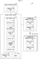
- Fig. 1 is a block diagram illustrating a configuration of an avatar display system 100 in accordance with Embodiment 1.
- the avatar display system 100 includes an image capturing device 10, an avatar display device 20, and an information communication device 30.
- the information communication device 30 is an information communication device used by a user, and is connected, via a network, with information communication devices 30a, 30b, 30c, ... used by other users.
- the information communication devices may be connected with each other via peer-to-peer (P2P) network or via a server (not illustrated).
- P2P peer-to-peer
- the avatar display system refers to a system that displays an avatar in an image display area of the information communication device
- the avatar display device refers to a device that displays an avatar in the image display area of the information communication device.
- the information communication device in which the avatar is to be displayed may be the information communication device 30 used by the user, any of the information communication devices 30a, 30b, 30c, ... used by the other users, or both of them.
- the image capturing device 10 is a device that captures an image of a person (user) whose avatar is to be generated.
- the image capturing device 10 can obtain a still image or a moving image, and includes a communication part 11 that transmits, to the avatar display device 20, the captured image data thus obtained.
- the image capturing device 10 may be a depth camera that is capable of not only capturing an image (e.g., an RGB image) but also measuring a distance (depth) to a subject.
- the distance may be measured by a known technique, for example, by three-dimensional light detection and ranging (Lidar), triangulation involving use of, e.g., an infrared ray, or a time-of-flight (TOF) method.
- the image capturing device 10 may be a stereo camera including two or more image-capturing parts.
- the captured image data obtained by the image capturing device 10 may include information indicating the depth.
- the captured image data including the information indicating the depth may also simply be referred to as "captured image data".
- the communication part 11 is a radio communication interface such as a Bluetooth (registered trademark) or Wi-Fi (registered trademark) communication interface, and is connectable with a network.
- the communication part 11 may be a wired connection interface.
- the image capturing device 10 may be a video camera having a communication function.
- the image capturing device 10 may be a personal computer, a mobile communication terminal, or the like each having a communication function and an image capturing device, for example.
- the mobile communication terminal may be a mobile phone or a tablet, for example.
- the avatar display device 20 may include a main control part 21, a communication part 22, and a memory 23.
- the main control part 21 may include an obtaining part 210, a second obtaining part 211, a generating part 212, a display part 213, and a texture generating part 214.
- the second obtaining part 211 may obtain (calculate) depth data from the captured image data. As will be described later, the second obtaining part 211 may obtain image data from the captured image data.
- the generating part 212 may compose a 3D model in accordance with the depth data to generate an avatar. In an aspect, the generating part 212 may combine, into the 3D model, texture data of the person generated by the texture generating part 214, so as to generate an avatar. A method for generating an avatar will be described in detail later.
- the display part 213 may use the avatar generated by the generating part 212 to generate avatar display data for use in displaying the avatar that is caused to follow a motion of the person, and may transmit the avatar display data to the information communication device 30 via the communication part 22.
- the information communication device 30 may transmit, as necessary, the avatar display data to the information communication devices 30a, 30b, 30c, .... Consequently, the display part 213 may display, in an image display area(s) 31 of all or part of the information communication devices 30, 30a, 30b, 30c, ... , the avatar that is caused to follow the motion of the person. Note that, in transmitting the avatar display data, the display part 213 may transmit only a difference between the avatar display data and the past avatar display data to the information communication device 30.
- the avatar display data may be a moving image of the avatar.
- the display part 213 may generate the avatar display data by replacing, with the avatar that is caused to follow the motion of the person, a person in each frame image in the moving image obtained by the image capturing device 10.
- the expression "replace” means any image processing with which a part of an image apparently seems to be replaced with another image.
- image processing encompass: processing with which, in the moving image, a roughly-taken area of the person is replaced with the avatar image; and processing with which an image of a person area and the avatar image are overlaid at a given transmittance.
- the display part 213 may generate the moving image of the avatar that is caused to follow the motion of the person. Specifically, by combining, into a given still image or a given moving image, the avatar that is caused to follow the motion of the person, the display part 213 may generate the moving image of the avatar that is caused to follow the motion of the person.
- the data for use in displaying the avatar that is caused to follow the motion of the person may be data of the avatar that is caused to follow the motion of the person.
- the display part 213 may transmit, to the information communication device 30 via the communication part 22, data indicating the avatar generated by the generating part 212 and motion data indicating a motion of the avatar that follows the motion of the person, thereby displaying, in the image display area(s) 31 of all or part of the information communication devices 30, 30a, 30b, 30c, ... , the avatar that is caused to follow the motion of the person.
- the texture generating part 214 may generate texture data of the person in accordance with the captured image data.
- the texture generating part 214 will be described in detail later.
- the main control part 21 of the avatar display device 20 may include at least one processor, and may be configured such that the at least one processor reads out an avatar display program stored in the memory 23 and executes the avatar display program so as to realize the functions of the generating part 212 and the display part 213.
- a program for realizing the function of the generating part 212 and a program for realizing the function of the display part 213 may be separated from each other and may be stored in memories in respective different devices. This configuration will be described later.
- the communication part 22 receives an image from the image capturing device 10, and transmits the avatar display data to the information communication device 30.
- the communication part 22 is a radio communication interface such as a Bluetooth (registered trademark) or Wi-Fi (registered trademark) communication interface, and is connectable with a network.
- the communication part 22 may be a wired connection interface.
- the main control part 21 records (stores), in the memory 23, the image obtained via the communication part 22.
- the memory 23 stores therein various programs to be executed by the main control part 21 and various data and/or the like to be referred to by the programs.
- the memory 23 also stores therein the avatar generated by the generating part 212.
- the memory 23 records therein a still image and a moving image obtained by the image capturing device 10.
- the information communication devices 30, 30a, 30b, 30c, ... are devices that can carry out wireless communication or radio communication with other information communication device(s).
- Examples of the information communication devices 30, 30a, 30b, 30c, ... encompass a personal computer, a mobile communication terminal, and a television and a 3D viewer each of which is for a video meeting and has a communication function.
- Examples of the 3D viewer encompass headsets and goggle type display devices each of which can display an xR (virtual reality (VR), augmented reality (AR), mixed reality (MR)) space and/or the like.
- VR virtual reality
- AR augmented reality
- MR mixed reality
- Each of the information communication devices 30, 30a, 30b, 30c, ... may include the image display area 31 and a communication part 32.
- the image display area 31 displays an image.
- the image display area 31 may be part or whole of a display included in the information communication device 30.
- the communication part 32 is a radio communication interface such as a Bluetooth (registered trademark) or Wi-Fi (registered trademark) communication interface, and is connectable with a network such as the Internet.
- the communication part 32 of the information communication device 30 may receive the avatar display data from the avatar display device 20 and transmit the avatar display data to the information communication devices 30, 30a, 30b, 30c, .... In this manner, each of the information communication devices may directly or indirectly receive the avatar display data from the avatar display device 20.
- the image display area(s) 31 of at least part of the information communication devices 30, 30a, 30b, 30c, ... may display, as a result of operation of an application(s) included in the at least part of the information communication devices, an avatar that follows a motion of a person in accordance with the avatar display data.
- the applications included in the information communication devices may be applications each of which realizes a communication system.
- the image display area 31 may be an area that is on a display or a viewer and that serves as a participant image display area for displaying a participant who participates in the communication system.
- An image displayed on the participant image display area may be a two-dimensional image or a three-dimensional image.
- a user of the avatar display system 100 can display, in the participant image display area, his/her avatar as a participant. Alternatively, the user may not display his/her avatar in the participant image display area of the information communication device 30 used by the user, and may display his/her avatar in the participant image display areas of the information communication devices 30a, 30b, 30c, ... used by other users.
- the communication system may be, for example, a communication system involving use of a moving image or a communication system involving use of a virtual space.
- the communication system involving use of a moving image is a system via which a user can communicate with another person while seeing a moving image or an avatar of the another person. Examples of the communication system encompass a teleconferencing system and a videotelephony system.
- the communication system involving use of a virtual space is a system via which a user can communicate with an avatar displayed in the virtual space.
- the virtual space may be the one that can be recognized with the VR, AR, or MR technique, and may be a VR space, for example. Examples of the system via which communication is carried out with the avatar displayed in the virtual space encompass metaverse and VRChat (registered trademark).
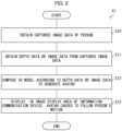
- Fig. 2 is a flowchart illustrating a flow of the avatar display method S 1.
- the avatar display method S 1 includes the following steps. First, in step S10, the image capturing device 10 may capture an image of a person and generate captured image data.
- the obtaining part 210 of the avatar display device 20 may obtain, via the communication part 22 and the communication part 11, the captured image data generated by the image capturing device 10, and may record the captured image data in the memory 23.
- the second obtaining part 211 may obtain (calculate), from the captured image data obtained by the obtaining part 210, depth data of the person.
- the second obtaining part 211 may obtain, as the depth data of the person, point group (three-dimensional) data.
- the second obtaining part 211 may analyze a correlation between multi-viewpoint images included in the captured image data to calculate the depth data.
- the second obtaining part 211 may calculate the depth data (e.g., point group (three-dimensional) data) of the person in accordance with the information indicating the depth included in the captured image data. In this process, the second obtaining part 211 may remove a background with reference to the depth data. In one example, the second obtaining part 211 can remove the background by removing, with reference to the depth data, an object(s) other than a largest object from among objects closest to the image capturing device 10. The removal is carried out in this manner since, at the time of capturing of an image for generating an avatar of a person, the person is often at a position closest to the image capturing device 10.
- the depth data e.g., point group (three-dimensional) data
- the generating part 212 composes a 3D model in accordance with the depth data calculated by the second obtaining part 211 so as to generate an avatar.
- the generating part 212 may record, in the memory 23, the avatar thus generated.
- the display part 213 generates avatar display data for use in displaying the avatar that is caused to follow a motion of the person, and transmits the avatar display data to the information communication device 30 via the communication part 22, thereby displaying, in the image display area(s) 31 of at least one of the information communication devices 30, 30a, 30b, 30c, ... , the avatar that is caused to follow the motion of the person.
- the display part 213 may generate the avatar that follows the motion of the person, by reading out the avatar stored in the memory 23 and causing the avatar to follow the motion of the person.
- the display part 213 may generate the avatar that follows the motion of the person, by changing an orientation of the avatar so as to follow motions (orientations) of various parts of the person and positioning the avatar so as to follow the position of the person. A method for determining the position and orientation of the person will be described later.
- the display part 213 may generate the avatar display data by (i) replacing, with the avatar that is caused to follow the motion of the person, a person in each image frame in the captured image data recorded in the memory 23 or (ii) combining the avatar that is caused to follow the motion of the person into each frame in a given still image or a given moving image. Then, the display part 213 may transmit the avatar display data to the information communication device 30 via the communication part 22.
- the display part 213 may generate motion data indicating a motion of the avatar that follows a motion of the person, and may transmit, as avatar display data, the motion data and the data of the avatar read out from the memory 23 to the information communication device 30 via the communication part 22.
- the display part 213 may generate motion data that gives, on a time-series basis, instructions as to motions (orientations) and positions of various parts of the avatar that respectively correspond to motions (orientations) and positions of various parts of the person.
- the generating part 212 composes, in accordance with depth data indicating a depth to a face of a person which depth data is obtained by the image capturing device 10, a 3D model of a head part of the person to generate an avatar of the person.
- depth data indicating a depth to a face of a person which depth data is obtained by the image capturing device 10.
- a 3D model of a head part of the person to generate an avatar of the person.
- a specific method therefor will be described below.
- the method described below is a method for generating an avatar of a head part of a person and displaying the avatar.
- a part of which avatar is to be generated and displayed is not limited to the head part (the part above the neck), but may be an upper-half body (a part including shoulders and a chest) or the whole body.
- the generating part 212 may generate, for example, an avatar of the head part of the person, an avatar of the upper-half body of the person, or an avatar of the whole body of the person.
- the generating part 212 may generate an avatar constituted by separate parts, for example, an avatar constituted by a head part and arms.
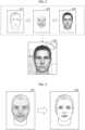
- Fig. 3 is a conceptual view illustrating an example of a procedure for generating an avatar of a head part.
- the obtaining part 210 obtains, from the image capturing device 10, captured image data for use in generation of an avatar.
- An image 331 in Fig. 3 is captured image data, obtained from the image capturing device 10, of a front face of a person whose avatar is to be generated.
- the second obtaining part 211 calculates, as depth data of the person, point group (three-dimensional) data 332.
- the point group (three-dimensional) data 332 is depth data representing the depth (three-dimensional shape) of the face by discrete point group data.
- the generating part 212 generates a face model in accordance with the point group data 332, and merges the face model with a head part model, so as to generate a head part avatar 333.
- the head part model will be described later.
- the generating part 212 may attach texture to the point group data 332 to generate a face model.
- the generating part 212 may construct, from the point group data 332, a 3D (three-dimensional) model with use of triangular meshes and attach texture thereto. The texture will be described later.
- the generating part 212 does not need to generate the face model with use of all pieces of depth data of the face.
- the generating part 212 may generate the avatar with use of, from among the pieces of depth data of the face, at least one of depth data corresponding to eyes, depth data corresponding to a nose, and depth data corresponding to a mouth.
- depth data corresponding to the eyes depth data of one or more feature points of the eyes and/or a part(s) around the eyes can be employed.
- the number of feature points is not particularly limited.
- the one or more feature points of the eyes and/or the part(s) around the eyes may include a feature point corresponding to an eyebrow.
- depth data corresponding to the nose depth data of one or more feature points of the nose and/or a part(s) around the nose can be employed.
- the number of feature points is not particularly limited.
- depth data corresponding to the mouth depth data of one or more feature points of the mouth and/or a part(s) around the mouth can be employed.
- the number of feature points is not particularly limited.
- the one or more feature points of the mouth and/or the part(s) around the mouth may include a feature point corresponding to a jaw.
- Fig. 4 is a view illustrating extracting, from point group data of a face, feature points corresponding to three parts, i.e., eyes, a nose, and a mouth.
- an image 341 is an image showing point group data of the whole face
- an image 342 is an image including only feature points corresponding to eyes, a nose, and a mouth extracted from the point group data. This shows that the position and orientation of a face can be determined only from arrangement of the eyes, nose, and mouth, and further shows that the image 342 has a smaller quantity of data than in the image 341.
- a method for generating a 3D model of a face in accordance with at least one of depth data corresponding to eyes, depth data corresponding to a nose, and depth data corresponding to a mouth is not limited to any particular one.
- the generating part 212 may generate a 3D model of a face with use of a learning model constructed by machine learning carried out using, as teaching data, combinations of (i) 3D models of various faces and (ii) at least one of depth data corresponding to eyes, depth data corresponding to noses, and depth data corresponding to mouths of these 3D models.
- Fig. 5 is a conceptual view illustrating a process for connecting a face model of a person with a head part model to generate the head part avatar 333.
- An image 352 is an image in which a boundary between the face and the hair in the head part model is determined by the generating part 212.
- An image 362 is an image in which a boundary between the face and the both sides of the face in the head part model is determined by the generating part 212.
- the generating part 212 can smoothly merges the face model and the head part model with each other by a known algorithm such as a blend shape technique, so as to generate the head part avatar 333.
- the avatar generated by the generating part 212 is in a dedicated file format for a three-dimensional avatar, for example, and is recorded in the memory 23.
- the data format may be, for example, a VRM format. However, this is not limitative. Note that some platforms or some applications for displaying an avatar cannot display the avatar recorded in the VRM format. In such a case, the avatar recorded in the VRM format may be converted into a data format that can be handled by the application. That is, the generating part 212 may generate an avatar in a data format compatible with the application or system in which the avatar is to be used.
- the display part 213 can replace, with the head part avatar 333 generated by the generating part 212, a person in the captured image data to generate avatar display data 334 including a background.
- the display part 213 may merge, with a given background image, the head part avatar 333 generated by the generating part 212 to generate avatar display data 334.
- the display part 213 may generate motion data indicating a motion of the avatar in the later-described manner, and then may merge the motion data with the head part avatar 333 generated by the generating part 212 to generate avatar display data 334.
- a face model and an upper-half body model may be combined.
- a face model and another body part model may be combined.
- the head part model, the upper-half body model, the whole body model, and the another body part model to be combined may be prepared in any of the following manners. That is, the existing models may be used after the sizes thereof are adjusted. Alternatively, new models may be generated in accordance with a result of a measurement of the person and may be stored in the memory 23. Further alternatively, from many existing models prepared in advance, a user may select one(s) or the generating part 212 may select a model similar to the image of the user captured by the image capturing device 10.
- the generating part 212 may combine the face model of the person with (i) a head part model, an upper-half body model, a whole body model, or another body part model of a character who is not the person or (ii) a head part model, an upper-half body model, a whole body model, or another body part of a different sex of himself/herself. With this, it is possible to generator an avatar different in character and/or sex from the person, while maintaining the feature(s) of the person's face.
- the following will explain a method for detecting an orientation of a head part of a person in a moving image.
- the orientation of the face can be expressed with use of a vector on a spherical coordinate system using, as an origin, a certain position preliminarily determined.
- the display part 213 detects at least one of the eyes, nose, and mouth of the person from the captured image of the person which captured image is captured by the image capturing device 10.
- the display part 213 refers to the orientation of the face determined in accordance with the position of at least one of the eyes, nose, and mouth having been detected, and replaces the image with another one so that the avatar faces that orientation.
- the position of the head part can be determined as coordinates representing a part that is a predetermined reference head part.
- the generating part 212 may generate the face model with use of generally-used skin color texture, for example.
- the generating part 212 may use texture that is generated in accordance with the captured image data.
- the texture generating part 214 may first generate texture data of the face of the person from the captured image data obtained by the obtaining part 210.
- Fig. 6 is a conceptual view illustrating a process for generating an avatar with use of the texture data generated by the texture generating part 214.
- the generating part 212 generates a face model 1521, such as the one shown in an image 152, in accordance with depth data calculated by the second obtaining part 211, such as the one shown in an image 151. Then, the generating part 212 combines, with the face model 1521 thus generated, the texture data generated by the texture generating part 214, so as to generate a face model such as that shown in the image 153. Consequently, it is possible to generate an avatar looking more like the actual one.
- the texture generating part 214 may fail to generate texture data of a part of the face of the person which part is not included in the captured image data, since the texture generating part 214 generates the texture data in accordance with the captured image data. For example, in some cases, texture data of both side ends of the face may be generated in accordance with the background of the person, as shown in the part indicated by an ellipse 1541 in an image 154. In order to deal with this, as shown in an image 155, the texture generating part 214 may compensate, with texture data of a part in the vicinity of the part of the face of the person which part is not included in the captured image data, the texture data of the part of the face of the person which part is not included in the captured image data.
- texture data prepared in advance for the character and/or the different sex may be used to generate an avatar.
- the avatar display system 100 and the avatar display method S1 configured as above, it is possible to generate an avatar of a user in accordance with an image of the user captured by the image capturing device 10 and to display the avatar in the image display area(s) 31 of the information communication device(s) 30, 30a, 30b, 30c, .... That is, it is possible to provide a technique for generating, from an image, an avatar of a user in accordance with the image and displaying the avatar.
- the generating part 212 generates an avatar with use of texture data generated by the texture generating part 214, it is possible to generate an avatar looking more like the actual one.
- an avatar to be generated is an avatar generated so that at least a face thereof corresponds to (looks like) a subject person, and a person who sees the avatar can immediately identify the subject person represented by the avatar.
- Such an avatar is useful in a situation in which the subject person needs to be reliably identified from the avatar but the person does not want to show his/her complete real face.
- the person can use, as necessary, an avatar generated from an image of the person captured after he/she has adjusted his/her appearance by shaving the beard or making up his/her face.
- FIG. 7 is a block diagram of a mobile terminal 40 in accordance with Variation 1 of Embodiment 1.
- the mobile terminal 40 is an example of the information communication device, and is communicable with the information communication devices 30a, 30b, 30c, ....
- the mobile terminal 40 may be a mobile phone or a tablet terminal that includes, e.g., an image capturing device 10 and that has a communication function.
- the mobile terminal 40 may include the image capturing device 10, a main control part 21, a memory 23, and a display 41.
- the image capturing device 10 has the functions described in Embodiment 1, and may be incorporated in the mobile terminal 40.
- the display 41 is a display screen of the mobile terminal 40, and the display 41 may have an image display area 411.
- the image display area 411 is, for example, an area in which an image is to be displayed by an application included in the mobile terminal 40.
- the main control part 21 may include an obtaining part 210, a second obtaining part 211, a generating part 212, a display part 213, and a texture generating part 214.
- the second obtaining part 211 may calculate depth data from captured image data.
- the generating part 212 may compose a 3D model in accordance with the depth data to generate an avatar, and may record the avatar in the memory 23.
- the display part 213 causes the avatar recorded in the memory 23 to follow an orientation of the person in a moving image, and may display, in the image display area 411 of the display 41 and the image display areas 31 of the information communication devices 30a, 30b, 30c, ... , the avatar that is cause to follow a motion of the person.
- the display part 213 may (i) replace, with the avatar that is caused to follow the motion of the person, a person in each frame image in a moving image captured by the image capturing device 10, (ii) combine the avatar that is caused to follow the motion of the person with a given still image or a given moving image, or (iii) generate data of the avatar that is caused to follow the motion of the person.
- the texture generating part 214 may generate texture data of the person in accordance with the captured image data.
- the function of the texture generating part 214 is as described in Embodiment 1.
- the main control part 21 may display, in the display 41, the data generated by the display part 213. Alternatively, the main control part 21 may transmit the data to the information communication devices 30a, 30b, 30c, ... to display, in the image display areas 31 of the information communication devices 30a, 30b, 30c, ... , the avatar that is caused to follow the motion of the person.
- the memory 23 is as described in Embodiment 1.
- the mobile terminal 40 in accordance with Variation 1 realizes, by a single device, the image capturing device 10, the avatar display device 20, and the information communication device 30 in accordance with Embodiment 1.
- the mobile terminal 40 has the functions of the image capturing device 10, the avatar display device 20, and the information communication device 30 in accordance with Embodiment 1.
- the entity that has these functions is not limited to the mobile terminal 40.
- a desktop personal computer (PC) may have these functions.
- the mobile terminal 40 includes the image capturing device 10 therein, and serves also as the information communication device having the image display area 411. Recently, mobile terminals have enhanced performance, and various applications are available therewith. Thus, also with the mobile terminal having all the above-described functions, it is possible to attain effects similar to those given by the avatar display system 100 described in Embodiment 1. In addition, the user can easily display his/her avatar in a moving image with use of a mobile terminal.
- FIG. 8 is a block diagram of an avatar display system 200 in accordance with Variation 2 of Embodiment 1.
- the avatar display system 200 may include a mobile terminal 40A and a desktop personal computer 50.
- the mobile terminal 40A may include an image capturing device 10, a main control part 21, a communication part 22, and a memory 23.
- the main control part 21 may include an obtaining part 210, a second obtaining part 211, a generating part 212, a display part 213, and a texture generating part 214.
- the main control part 21 may transmit, to the desktop personal computer 50 via the communication part 22, avatar display data for use in displaying an avatar that is caused to follow a motion of a person.
- a configuration of the mobile terminal 40A is identical to the configuration of the mobile terminal 40 described in Variation 1, except that the mobile terminal 40A includes the communication part 22 and does not include the display 41.
- the desktop personal computer 50 includes a display 51 and a communication part 52.
- the display 51 may include an image display area 511.
- the communication part 52 may receive avatar display data from the mobile terminal 40A.
- the desktop personal computer 50 may use the avatar display data received from the mobile terminal 40A to display, in the image display area 511 of the display 51, an avatar that is cased to follow a motion of the person.
- the desktop personal computer 50 is an embodiment of the information communication device 30 described in Embodiment 1.
- the mobile terminal 40A may include the image capturing device 10, the obtaining part 210, the second obtaining part 211, the generating part 212, the display part 213, and the texture generating part 214. However, unlike the mobile terminal 40 in accordance with Variation 1, the mobile terminal 40A may display, in the display 51 of the desktop personal computer 50, an avatar that is caused to follow a motion of a person, instead of displaying that avatar in its own display.
- the mobile terminal 40A may (i) generate the avatar display data for use in displaying of the avatar that is caused to follow the motion of the person and (ii) display, in the desktop personal computer 50, the avatar display data thus generated.
- the display part 213 may be included in the desktop personal computer 50, rather than in the mobile terminal 40A (not illustrated).
- Fig. 9 is a block diagram illustrating a configuration of a mobile terminal 40B in accordance with Embodiment 2 of the present invention.
- the mobile terminal 40B may include an image capturing device 10, a main control part 21, a memory 23, and a display 41.
- the main control part 21 may include an obtaining part 210, a second obtaining part 211, a generating part 212, a display part 213, a converting part 215, and a texture generating part 214.
- the image capturing device 10, the obtaining part 210, the second obtaining part 211, the generating part 212, the display part 213, the texture generating part 214, and the memory 23 are similar to those described in Embodiment 1.
- the mobile terminal 40B also serves as the information communication device 30 described in Embodiment 1.
- the mobile terminal 40B may include an application for a communication system involving use of a moving image.
- the moving image used in the communication system may be a two-dimensional image or a three-dimensional image.
- the communication system involving use of a moving image may be, for example, a teleconferencing system or a communication system in a virtual space (VR space) such as metaverse.
- VR space virtual space
- the teleconferencing system is a system in which two or more persons carry out a meeting, a conference, a conversation, chatting, or the like via a mobile phone(s), a personal computer(s), a video-telephone(s), and/or the like over the Internet or a dedicated line, and may also be called a web meeting system or a video meeting system.
- the communication system involving use of a moving image used in Embodiment 2 can be carried out with use of a known application of any kind.
- the display 41 displays a communication system 411 (e.g., a meeting room in a teleconferencing system) involving use of a moving image, and a participant image display area 4111 is displayed therein.
- the participant image display area 4111 displays a participant(s) who participate(s) in the communication system involving use of a moving image.
- the participant image display area 4111 displays images of users of the mobile terminal 40B and information communication devices 30a, 30b, 30c, ....
- the participant image display area 4111 corresponds to the image display area 31 described in Embodiment 1.
- the display part 213 may display, in the participant image display area 4111, an avatar(s) that is/are caused to follow a motion(s) of the participant(s).
- the user of the mobile terminal 40B may capture an image of himself/herself with the mobile terminal 40B. Then, the user may select a favorite one from among the images thus captured, and may cause the generating part 212 to generate an avatar. In one example, the user may select a head part or a head part area in the favorite image and tap an avatar generating button. In response to this, the generating part 212 generates, from the image of the selected area, an avatar of an upper-half body or a head part, and records the avatar in the memory 23.
- the user may designate, in the communication system involving use of a moving image, the participant image display area 4111 in which the user's image is to be displayed. Specifically, for example, the user may enter or select his/her name or ID to be displayed in the image. Note that entry or selection of the other participant's name or ID is prohibited.
- the display part 213 may replace the upper-half body, the whole body, or the head part of a user in a moving image captured by the image capturing device 10 with an avatar that is caused to follow a motion of the upper-half body, the whole body, or the head part of the user.
- the main control part 21 may display, in the participant image display area 4111, the moving image in which the user's image is replaced with avatar.
- the main control part 21 may transmit the image in which the user's image is replaced with the avatar to the information communication device(s) used by the other participant(s) via the application for the communication system involving use of a moving image.
- the converting part 215 may convert a data format of the avatar generated by the generating part 212. Specifically, the converting part 215 may convert the data format of the avatar so that the data format is compatible with an image data format of the application used by the mobile terminal 40B.
- An image data format available in an application for the teleconferencing system may vary depending on the application.
- the converting part 215 may convert the data format (e.g., VRM format) of the avatar into a data format available in the application. With this, it is possible to display the avatar, regardless of the kind of the communication system involving use of a moving image.
- an avatar display method S2 for converting a data format of an avatar.
- Fig. 10 is a flowchart illustrating a flow of the avatar display method S2 to be executed by the mobile terminal 40B.
- the avatar display method S2 includes the following steps.
- the image capturing device 10 may capture an image of a person and generate captured image data.
- the obtaining part 210 of the avatar display device 20 may obtain, via the communication part 22 and the communication part 11, the captured image data generated by the image capturing device 10.
- the second obtaining part 211 may obtain (calculate) depth data of the person from the captured image data obtained by the obtaining part 210. As will be described later, the second obtaining part 211 may obtain image data of the person from the captured image data. Then, in step S22, the generating part 212 composes a 3D model in accordance with the depth data calculated by the second obtaining part 211 so as to generate an avatar. The generating part 212 may record, in the memory 23, the avatar thus generated.
- the converting part 215 may convert the data format of the avatar in accordance with the application of the communication system involving use of a moving image and that is used by the mobile terminal 40B.
- the display part 213 may display, in the participant image display area 4111 of the display 41 of the mobile terminal 40B (information communication device), the avatar that is caused to follow a motion of the person.
- the display part 213 may transmit the avatar in the converted data format to the information communication devices 30a, 30b, 30c, ... via the communication part 22, and may display the avatar in the image display areas 31 (participant image display areas) of the information communication devices 30a, 30b, 30c, ...
- Embodiment 2 With the mobile terminal 40B and the avatar display method S2 in accordance with Embodiment 2 configured as above, it is possible to display an avatar of a user in the communication system involving use of a moving image (e.g., a teleconferencing system). With this, it is possible to achieve effects similar to those given by Embodiment 1. Particularly, in a case of using the teleconferencing system, in which the person who is speaking needs to be clearly identified, the following merits can be achieved. That is, since an avatar in accordance with Embodiment 2 is generated in accordance with a user's image, it is possible to clearly identify a user represented by the avatar.
- a moving image e.g., a teleconferencing system
- Embodiment 2 Note that the converting part 215 described in Embodiment 2 can be combined with Embodiment 1.
- Fig. 11 is a block diagram illustrating a configuration of an avatar display system 300 in accordance with Embodiment 3 of the present invention.
- the avatar display system 300 includes an image capturing device 10, an avatar display device 20, and an information communication device 30.
- the image capturing device 10 and the information communication device 30 are similar to the devices described in Embodiment 1. Therefore, descriptions of the image capturing device 10 and the information communication device 30 are omitted.
- the avatar display device 20 may include a main control part 21, a communication part 22, and a memory 23.
- the main control part 21 may include an obtaining part 210, a second obtaining part 211, a generating part 212, a display part 213, a texture generating part 214, and a tracking part 216.
- the obtaining part 210, the second obtaining part 211, the generating part 212, the display part 213, and the texture generating part 214 are similar to those described in Embodiment 1.
- the tracking part 216 may track a face of a person in an image obtained by the image capturing device 10. Furthermore, the tracking part 216 may track a neck of the person in the image. The tracking refers to detection of a position.
- the display part 213 may cause, with reference to an orientation of the face tracked, an avatar to follow a motion of the person.
- the display part 213 may cause, with reference to the orientation of the neck tracked, the avatar to follow a motion of a body part of the person which body part includes the neck and a part lower than the neck. A specific operation therefor will be described below.
- the generating part 212 may generate, from the image obtained by the image capturing device 10, not only a head part model of the person but also a model of a body part including a neck of the person and a part lower than the neck.
- the body part including the neck of the person and the part lower than the neck is, for example, an upper-half body not including the head part.
- the body part including the neck of the person and the part lower than the neck may simply be referred to as a "body part".
- the body part does not need to be made to look like the person as the face model is.
- the body part model may an existing body part model.
- the body part model may be the one generated by excluding a head part from an existing upper-half body model.
- the tracking part 216 may track (pursue), e.g., eyes of the face of the person.
- the tracking of a certain subject in an image can be carried out with use of a known program or a known application.
- a subject to be tracked may be any of eyes, a nose, and a mouth.
- the tracking part 216 may work out an orientation of the face from the shapes and arrangement of the two eyes tracked.
- a method for working out the orientation of the face is similar to the method for determining the orientation of the face described in Embodiment 1.
- the tracking part 216 may track the face of the person as well as the neck of the person.
- the neck is recognized as, for example, a cylindrical area extending downward from the face.
- the tracking part 216 may work out the orientation of the neck tracked.
- the orientation of the neck refers to any of directions (front, rear, left, and right) toward which the neck is bent. In other words, the orientation of the neck refers to a direction toward which the neck is inclined.
- the orientation of the neck is determined in the following manner. That is, when the neck is inclined toward the left or right, it is determined that the body part is inclined toward the left or right at an angle of that time. Meanwhile, when a ratio in width between an upper part of the neck and a lower part of the neck changes, it is determined that the body part is inclined toward the front or rear at a given angle in accordance with the ratio.
- the purpose of tracking the neck is to process the head part and the body part of the avatar individually.
- the generating part 212 may separately generate the model of the head part of the person and the model of the body part including the neck of the person and the part lower than the neck.
- the head part moves independently of the body part.
- the orientation of the neck changes in conjunction with the orientation of the body part. For example, in a case where the neck is inclined toward the right, the body part is considered to be inclined toward the right.
- the display part 213 may move the head part of the avatar in accordance with a result of tracking of the eyes, nose, and mouth of the person, and may move the body part of the avatar with reference to the orientation of the neck of the person. With this, it is possible to display the avatar in a motion more looking like an actual one.
- Moving the head part of the avatar means the following operation: the display part 213 changes the orientation of the head part model generated by the generating part 212 so that the head part model follows the orientation of the face worked out by the tracking part 216 and displays the head part model in the image display area(s) 31 of at least one of the information communication devices 30, 30a, 30b, 30c, ... .
- Moving the body part of the avatar means the following operation: the display part 213 changes the orientation of the body part model generated by the generating part 212 so that the body part model follows the orientation of the neck worked out by the tracking part 216 and displays the body part model in the image display area(s) 31 of at least one of the information communication devices 30, 30a, 30b, 30c, ....
- the display part 213 may generate a head part model or a body model whose orientation has been changed. Alternatively, the display part 213 may generate motion data that gives an instruction to change the orientation of the head part model or the body model.
- the shoulder part may be tracked so that the position and orientation thereof are detected, and accordingly the body part model may be twisted.
- the arms and legs move independently of the body part.
- the positions and orientations of the arms and legs may be tracked in the image, and orientations of models of arms and legs additionally generated may be changed.
- FIG. 12 is a flowchart illustrating a flow of the avatar display method S3 to be executed by the avatar display system 300. Note that, in an example described here, the avatar display method S3 displays an avatar including both a head part and a body part.
- the avatar display method S3 includes the following steps.
- the obtaining part 210 may obtain captured image data of a person which captured image data is obtained by the image capturing device 10.
- the tracking part 216 may track eyes, a nose, and a mouth of the person on the basis of the captured image data obtained by the obtaining part 210.
- the tracking of the eyes, nose, and mouth of the person may be carried out in accordance with depth data or image data obtained from the captured image data.
- the display part 213 may move the head part of the avatar in accordance with a result of tracking of the eyes, nose, and mouth of the person.
- the display part 213 may move the body part of the avatar with reference to an orientation of a neck of the person tracked.
- the display part 213 may move the avatar by generating avatar display data for use in displaying the avatar that is caused to follow motions of a head part and a body part of the person in the moving image.
- the moving image in which the avatar moves is displayed in the image display area 31.
- a head part model and a body part model of a person may be separately generated, the head part of an avatar may be moved in accordance with a result of tracking of eyes, a nose, and a mouth, and the body part of the avatar may be moved with reference to an orientation of a neck of the person.
- Embodiment 3 can be combined with Embodiment 1 or 2.
- An avatar generating device in accordance with Embodiment 4 includes: an obtaining part that obtains captured image data of a person; a second obtaining part that calculates depth data of the person from the captured image data; a generating part that composes a 3D model in accordance with the depth data to generate to generate an avatar; and an output part that outputs the avatar thus generated.
- the generating part is similar to the generating part 212 described in Embodiments 1 to 3 described above.
- the output part is similar to the communication part 22 described in Embodiments 1 to 3 described above.
- the avatar generating device may include a memory that records therein an avatar generated by the generating part.
- the memory is similar to the memory 23 described in Embodiments 1 to 3 described above.
- An avatar generated by the avatar generating device in accordance with Embodiment 4 can be output externally via the output part.
- the avatar generating device may output the avatar to a virtual space.
- the virtual space encompass: a virtual reality space (e.g., VRChat (registered trademark)) a whole of which is constituted by a computer graphics image and which is called “virtual reality (VR)"; an augmented reality space which is a combination of a real space and a computer graphics image and which is called “augmented reality (AR)”; and a mixed reality space which is made of a real space and virtual information and/or the like that are overlaid and which is called “mixed reality (MR)".
- VRChat registered trademark
- VR virtual reality
- AR augmented reality
- MR mixed reality
- a virtual space in which a user can participate via the Internet.
- a virtual space displayed by a given display device e.g., a display, a viewer.
- Outputting an avatar to a virtual space means displaying an avatar in a virtual space such as that listed above.
- the avatar generating device may include the above-described converting part 215.
- a user can generate his/her avatar and display the avatar in various virtual spaces.
- the image capturing device 10 described in Embodiments 1 to 4 may employ a color film to obtain color data of a person.
- the generating part 212 can use depth data and color data to generate an avatar. That is, the generating part 212 can add, to the avatar, hue of the face, hair, clothing, and/or the like of the person.
- the avatar described in each of Embodiments 1 to 5 can be caused to follow not only an orientation of a person but also a facial expression of the person.
- the display part 213 may detect a feature point in a face of a person from captured image of the person which captured image is captured by the image capturing device 10.
- the display part 213 may detect, for example, one or more feature points of eyes and/or a part(s) around the eyes, one or more feature points of a nose and/or a part(s) around the nose, and one or more feature points of a mouth and/or a part(s) around the mouth.
- the one or more feature points of the eyes and/or the part(s) around the eyes may include a feature point corresponding to an eyebrow.
- the one or more feature points of the mouth and/or the part(s) around the mouth may include a feature point corresponding to a jaw.
- the number of feature points in the face of the person that are to be detected to follow a facial expression may be smaller than the number of feature points in the face of the person that are to be detected to generate an avatar.
- the number of feature points to be detected increases, it is possible to express a facial expression of the person more accurately.
- information processing takes longer. This may cause delay in generation of a facial expression of the avatar, thereby making it difficult to display the avatar on a real-time basis.
- the number of feature points for expressing the facial expression is reduced. This enables quick information processing, thereby making it possible to generate an avatar with a lot of facial expressions on a real-time basis.
- the feature points in the face of the person that are to be detected to follow the facial expression may be, for example, the ones illustrated in Fig. 16 .
- the display part 213 can deform a face model of the avatar so as to cause a facial expression of the avatar to follow a facial expression of the person.
- Carrying out this process in accordance with the change in the coordinates of the feature points of the eyes and/or the part(s) around the eyes, the nose and/or the part(s) around the nose, and the mouth and/or the part(s) around the mouth makes it possible to deform the shapes of the eyes, nose, and mouth of the avatar in accordance with the facial expression of the person, thereby making it possible to cause the facial expression of the avatar to follow the facial expression of the person.
- the generating part 212 may carry out the following. That is, the generating part 212 may record, from among the feature points in the face of the person that are detected to generate the avatar, the coordinates of the feature points in the face of the person that are detected to follow the facial expression so that the coordinates of the feature points in the face of the person that are detected to follow the facial expression are associated with a face model. Then, in accordance with a difference between (i) the coordinates of the feature points associated with the face model and (ii) coordinates of detected feature points, the display part 213 may deform the face model with use of a known algorithm such as a blend shape technique. With this, the display part 213 can cause a facial expression of the avatar to follow a facial expression of the person on a real-time basis.
- a known algorithm such as a blend shape technique
- the generating part 212 may prepare a 3D model part(s) and combine the 3D model part(s) into the avatar, for example.
- the display part 213 may reflect, in a facial expression of the avatar, a facial expression designated by the user.
- the avatar may be made to have a smile expression.
- the display part 213 fixes (does not deform) only the feature points for making smile (e.g., the feature points of the mouth and/or the part(s) around the mouth) and changes the other feature points in accordance with the coordinates of the detected feature points. This makes it possible to express a smile expression even when the person is angry.
- a character other than a human is used as an avatar.
- feature points in a face of the character may be associated with feature points in a face of a person in advance. Consequently, a facial expression of the person can be reflected in a facial expression of the character. In this manner, a facial expression of a user can be reflected even in a character other than a human.
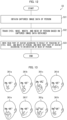
- the display part 213 may use, e.g., templates such as images 361a to 361h shown in Fig. 13 to cause a facial expression of an avatar to follow a facial expression of a person.
- the display part 213 may carry out image analysis on a facial expression of the person in the captured image. Then, if it is determined that the facial expression looks like one of the images 361a to 361h, the facial expression of the avatar may be caused to follow the one image.
- Fig. 14 shows a procedure for this case.
- An image 371 shown in Fig. 14 is an original image.
- a part of the background is cut away along an outline of a person, as shown in the image 372.
- the outline of the part to be cut away may be a rough outline that is slightly separated outwardly from the actual outline of the person.
- an avatar of the person is put into the cut area, and the avatar and the background are smoothly blended in a gap therebetween. This procedure enables the replacement that yields an image including the desired background and the avatar, as in an image 373.
- the face of the avatar is made to look like the face of the person as much as possible.
- parts other than the face do not need to be made to look like corresponding parts of the person.
- the hairstyle of the avatar may be changed.
- an accessory e.g., a necklace, eye glasses
- an avatar of a person may be generated so that a body part other than a head part may be replaced with a body part of a body shape different from that of the person.
- Embodiments 1 to 8 have dealt with the example in which the avatar display device 20 calculates depth data from captured image data of a person (user), and composes a 3D model of the person in accordance with the depth data to generate an avatar.
- the data for use in generation of the avatar is not limited to the depth data.
- an avatar may be generated from image data.
- the description in Embodiment 9 will discuss a configuration in which a second obtaining part 211 obtains image data from captured image data, and a generating part 212 composes a 3D model in accordance with the image data to generate an avatar.
- the image data may be, for example, an RGB image data. However, this is not limitative.
- the second obtaining part 211 may extract image data of a person from captured image data.
- the second obtaining part 211 may use a known edge detection algorithm to extract an outline from captured image data, and accordingly discriminate a person from a background in the captured image data. Then, the second obtaining part 211 extracts image data of the person.
- Fig. 15 is a conceptual view illustrating an example of a result of extracting an outline of a person from captured image data.
- a left image 151 in Fig. 15 shows one example of captured image data, and includes a person 153 and a background 154.
- a right image 152 in Fig. 15 shows one example of an image including an outline that the second obtaining part 211 has extracted from the image 151.
- the second obtaining part 211 removes, in accordance with the image 152, a part outside an outline of a largest object, thereby removing the background 154 from the image 151. Consequently, the second obtaining part 211 can obtain image data of the person 153.
- the generating part 212 may obtain a feature point(s) from the image data of the person.
- the generating part 212 may use a known feature point detection algorithm to detect the feature point(s) in the face of the person.
- Fig. 16 is a conceptual view illustrating an example of a result of detecting, from image data of a person 161, feature points P in a face of the person 161.
- the generating part 212 can detect, from the detected feature points P in the face of the person 161, arrangement of eyes, a nose, and a mouth in the face of the person 161 as well as a size of the face.
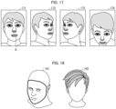
- FIG. 17 is a conceptual view illustrating an example of a result of extracting, from various pieces of image data including the person in different orientations, feature points Q of eyes, a nose, and a mouth of a person.
- the generating part 212 can extract the feature points Q of the eyes, nose, and mouth in the face of the person not only from an image 171 of the person facing forward but also from images 172 to 274 of the person facing various directions in a similar manner to that described above.
- the tracking template is a template used to pursue (track) an orientation of a face of a person.
- the tracking template indicates various kinds of reference arrangement of feature points Q of eyes, a nose, and a mouth in a face of a person, and the various kinds of reference arrangement are respectively associated with various orientations of the face of the person.
- the tracking template can be generated by the following manner involving use of images of various persons (persons of various races may be included) in various orientations. That is, feature points Q of eyes, noses, and mouths of the various persons in these images are detected in the above-described manner, and machine learning is carried out with use of the feature points Q thus detected. From an image of a person whose orientation is to be tracked, feature points of eyes, a nose, and a mouth may be detected and the detected feature points may be compared with the tracking template. With this, it is possible to estimate an orientation of the face of the person.
- the generating part 212 may use any of the references in the tracking template to obtain information of feature points Q of eyes, a nose, and a mouth in a face of the person. For example, when the feature points Q of the eyes, nose, and mouth are detected from the images 171 to 174, the feature points Q thus detected may be compared to arrangement indicated as a reference by the tracking template generated in advance, so that differences in arrangement and size between the feature points Q of the eyes, nose, and mouth of the person and the reference can be obtained.
- the generating part 212 may generate a 3D model of a front side part of the face of the person.
- a method for generating a 3D model of the face in accordance with the information (the differences in arrangement and size from the reference) of the feature points Q of the eyes, nose, and mouth is not limited to any particular one.
- the generating part 212 may generate a 3D model of the face with use of a learning model constructed by machine learning that uses, as teaching data, combinations of (i) 3D models of various faces and (ii) pieces of information (differences in arrangement and size from the reference) of feature points Q of eyes, noses, and mouths of these 3D models.
- Fig. 18 is a conceptual view illustrating (i) an example of a 3D model of a front side part of a face and (ii) an example of a 3D model of a head part not including the front side part of the face.
- the generating part 212 may generate the 3D model of the head part by merging, with a 3D model 181 of a front side part of a face generated in accordance with feature points Q of eyes, a nose, and a mouth of a person, a 3D model 182 of a head part including hair stored in a memory 23 in advance, for example.
- the generating part 212 may merge the two 3D models with each other together with, e.g., adjustment of the sizes of the 3D models, calibration (correction of distortion in an image caused by an angle), and/or morphing (image processing for smoothing a seam between the two 3D models).
- the generating part 212 may merge, with the head part model, an upper-half body model or a another body part model and/or texture that is generated in accordance with captured image data.
- An avatar generated by the generating part 212 in this manner may be displayed by a display part 213, similarly to Embodiment 1.
- the display part 213 may use the above-described tracking template to detect an orientation of a face of a person, and may cause an orientation of the face of the avatar to follow the orientation of the face of the person.
- the display part 213 may detect a given feature point(s) in the face of the person, and may cause a facial expression of the avatar to follow a facial expression of the person.
- the avatar display device 20 may use, in place of or in addition to depth data of a person, image data of the person to generate an avatar of the person. That is, the second obtaining part 211 may obtain the depth data or image data of the person. This also applies to any of the avatar display devices and avatar generating devices in accordance with Embodiments 1 to 5 described above.
- Control blocks of the avatar display device 20 and the mobile terminals 40, 40A, and 40B can be realized by a logic circuit (hardware) provided in an integrated circuit (IC chip) or the like or can be alternatively realized by software as executed by a central processing unit (CPU).
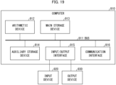
- the avatar display device and the like may be made of a computer (electronic computer) such as that illustrated in Fig. 19 .
- Fig. 19 is a block diagram illustrating an example of a configuration of a computer 910 usable as an avatar display device.
- the computer 910 includes an arithmetic device 912, a main storage device 913, an auxiliary storage device 914, an input/output interface 915, and a communication interface 916 which are connected to each other via a bus 911.
- Each of the arithmetic device 912, the main storage device 913, and the auxiliary storage device 914 can be, for example, a central processing unit (CPU), a random access memory (RAM), a solid state drive, or a hard disk drive.
- the input/output interface 915 is connected with (i) an input device 920 via which a user inputs various information to the computer 910 and (ii) an output device 930 via which the computer 910 outputs various information to the user.
- the input device 920 and the output device 930 can be incorporated into the computer 910 or can be devices which are (externally) connected to the computer 910.
- the input device 920 can be a button, a keyboard, a mouse, a touch sensor, or the like
- the output device 930 can be a lamp, a display, a printer, a speaker, or the like.
- the communication interface 916 is an interface via which the computer 910 communicates with an external device.
- the auxiliary storage device 914 stores an information processing program for causing the computer 910 to function as the avatar display device and the like.
- the arithmetic device 912 loads, on the main storage device 913, the information processing program stored in the auxiliary storage device 914, and executes a command included in the information processing program so that the computer 910 functions as each part of the avatar display device and the like.
- a storage medium which is included in the auxiliary storage device 914 for recording information such as the information processing program only needs to be a computer-readable "non-transitory tangible medium" and can be, for example, a tape, a disk, a card, a semiconductor memory, a programmable logic circuit, or the like.
- a program recorded in a storage medium outside the computer 910 or a program supplied to the computer 910 via any transmission medium can be used to function the computer 910 in the above-described way.
- the present invention can also be achieved in the form of a computer data signal in which the above-described program is embodied via electronic transmission and which is embedded in a carrier wave.
- An avatar display device includes: an obtaining part that obtains captured image data of a person; a second obtaining part that obtains, from the captured image data, depth data or image data of the person; a generating part that composes a 3D model in accordance with the depth data or image data to generate an avatar; and a display part that displays, in an image display area of an information communication device, the avatar that is caused to follow a motion of the person.
- An avatar generating device includes: an obtaining part that obtains captured image data of a person; a second obtaining part that obtains, from the captured image data, depth data or image data of the person; a generating part that composes a 3D model in accordance with the depth data or image data to generate an avatar; and an output part that outputs the avatar thus generated.
- a program causes at least one processor to execute: an obtaining process for obtaining captured image data of a person; a second obtaining process for obtaining, from the captured image data, depth data or image data of the person; a generating process for composing a 3D model in accordance with the depth data or the image data to generate an avatar; and a display process for displaying, in an image display area of an information communication device, the avatar that is caused to follow a motion of the person.
- the present invention is not limited to the embodiments, but can be altered by a skilled person in the art within the scope of the claims.
- the present invention also encompasses, in its technical scope, any embodiment derived by combining technical means disclosed in differing embodiments.
Landscapes
- Engineering & Computer Science (AREA)
- Physics & Mathematics (AREA)
- General Physics & Mathematics (AREA)
- Theoretical Computer Science (AREA)
- Computer Graphics (AREA)
- Software Systems (AREA)
- Architecture (AREA)
- Computer Hardware Design (AREA)
- General Engineering & Computer Science (AREA)
- Multimedia (AREA)
- Computer Vision & Pattern Recognition (AREA)
- Geometry (AREA)
- Processing Or Creating Images (AREA)
- Image Processing (AREA)
- Two-Way Televisions, Distribution Of Moving Picture Or The Like (AREA)
Abstract
Description
- The present invention relates to an avatar display device, an avatar generating device, and a program.
- There have been known conventional techniques for expressing a person by computer graphics. For example, Patent Literature 1 discloses a technique for generating a facial animation using a face mesh. Patent Literature 1 states that this technique can generate a realistic facial animation of a face image of a person.
- Published
Japanese Translation of PCT International Application, Tokuhyo, No. 2009-523288 - Although the conventional technique such as that described above can reproduce realistic facial expressions, the facial expressions are merely an animation. Thus, such a technique is not a technique for generating an avatar. Recently, a lot of attraction is paid to an avatar, which is another body of a user in an image. There is a demand for a technique for generating an avatar that expresses a user in an effective way.
- In order to attain the above object, an avatar display device in accordance with an aspect of the present invention includes: an obtaining part that obtains captured image data of a person; a second obtaining part that obtains, from the captured image data, depth data or image data of the person; a generating part that composes a three-dimensional model in accordance with the depth data or the image data to generate an avatar; and a display part that displays, in an image display area of an information communication device, the avatar that is caused to follow a motion of the person.
- In order to attain the above object, an avatar generating device in accordance with an aspect of the present invention includes: an obtaining part that obtains captured image data of a person; a second obtaining part that obtains, from the captured image data, depth data or image data of the person; a generating part that composes a three-dimensional model in accordance with the depth data or the image data to generate an avatar; and an output part that outputs the avatar thus generated.
- The avatar display device and the avatar generating device in accordance with the above aspects of the present invention can be realized by a computer. In this case, the present invention encompasses: a control program for an avatar display device which control program causes a computer to operate as each part (software element) of the avatar display device so that the avatar display device can be realized by the computer; and a computer-readable storage medium in which the control program is stored.
-
-
Fig. 1 is a block diagram illustrating an avatar display system in accordance with Embodiment 1 of the present invention. -
Fig. 2 is a flowchart illustrating a flow of an avatar display method in accordance with Embodiment 1. -
Fig. 3 is a conceptual view illustrating an example of a procedure for generating an avatar of an upper-half body and displaying the avatar. -
Fig. 4 is a view illustrating extracting, from point group data of a face, only data corresponding to eyes, a nose, and a mouth. -
Fig. 5 is a conceptual view illustrating a process for jointing a face model of a person to an upper-half body model to generate an avatar. -
Fig. 6 is a conceptual view illustrating a process for generating an avatar with use of texture data. -
Fig. 7 is a block diagram of a mobile terminal in accordance with Variation 1 of Embodiment 1. -
Fig. 8 is a block diagram of an avatar display system in accordance withVariation 2 of Embodiment 1. -
Fig. 9 is a block diagram illustrating a configuration of a mobile terminal in accordance withEmbodiment 2 of the present invention. -
Fig. 10 is a flowchart illustrating a flow of an avatar display method in accordance withEmbodiment 2. -
Fig. 11 is a block diagram illustrating a configuration of an avatar display system in accordance with Embodiment 3 of the present invention. -
Fig. 12 is a flowchart illustrating a flow of an avatar display method in accordance with Embodiment 3. -
Fig. 13 shows examples of facial expressions to be followed by an avatar. -
Fig. 14 is a conceptual view illustrating a procedure for replacing a background and a person in a moving image with other ones. -
Fig. 15 is a conceptual view illustrating an example of a result of extracting an outline of a person from captured image data. -
Fig. 16 is a conceptual view illustrating an example of a result of extracting, from image data, feature points in a face of a person. -
Fig. 17 is a conceptual view illustrating an example of a result of extracting, from image data, feature points corresponding to eyes, a nose, and a mouth in a face of a person. -
Fig. 18 is a conceptual view illustrating (i) an example of a 3D model of a front side part of a face and (ii) an example of a 3D model of a head part not including the front side part of the face. -
Fig. 19 shows an example of a configuration in which each part of an avatar display device and the like is realized by a computer. - The following description will discuss, in detail, an embodiment of the present invention.
Fig. 1 is a block diagram illustrating a configuration of an avatar display system 100 in accordance with Embodiment 1. The avatar display system 100 includes an image capturingdevice 10, anavatar display device 20, and aninformation communication device 30. Theinformation communication device 30 is an information communication device used by a user, and is connected, via a network, withinformation communication devices - In Embodiment 1, the avatar display system refers to a system that displays an avatar in an image display area of the information communication device, and the avatar display device refers to a device that displays an avatar in the image display area of the information communication device. The information communication device in which the avatar is to be displayed may be the
information communication device 30 used by the user, any of theinformation communication devices - The image capturing
device 10 is a device that captures an image of a person (user) whose avatar is to be generated. The image capturingdevice 10 can obtain a still image or a moving image, and includes acommunication part 11 that transmits, to theavatar display device 20, the captured image data thus obtained. - In an aspect, the
image capturing device 10 may be a depth camera that is capable of not only capturing an image (e.g., an RGB image) but also measuring a distance (depth) to a subject. The distance may be measured by a known technique, for example, by three-dimensional light detection and ranging (Lidar), triangulation involving use of, e.g., an infrared ray, or a time-of-flight (TOF) method. In an aspect, theimage capturing device 10 may be a stereo camera including two or more image-capturing parts. The captured image data obtained by theimage capturing device 10 may include information indicating the depth. The captured image data including the information indicating the depth may also simply be referred to as "captured image data". - For example, the
communication part 11 is a radio communication interface such as a Bluetooth (registered trademark) or Wi-Fi (registered trademark) communication interface, and is connectable with a network. For another example, thecommunication part 11 may be a wired connection interface. The image capturingdevice 10 may be a video camera having a communication function. Alternatively, theimage capturing device 10 may be a personal computer, a mobile communication terminal, or the like each having a communication function and an image capturing device, for example. The mobile communication terminal may be a mobile phone or a tablet, for example. - The
avatar display device 20 may include amain control part 21, acommunication part 22, and amemory 23. Themain control part 21 may include an obtainingpart 210, a second obtainingpart 211, a generatingpart 212, adisplay part 213, and atexture generating part 214. - The second obtaining
part 211 may obtain (calculate) depth data from the captured image data. As will be described later, the second obtainingpart 211 may obtain image data from the captured image data. The generatingpart 212 may compose a 3D model in accordance with the depth data to generate an avatar. In an aspect, the generatingpart 212 may combine, into the 3D model, texture data of the person generated by thetexture generating part 214, so as to generate an avatar. A method for generating an avatar will be described in detail later. - The
display part 213 may use the avatar generated by the generatingpart 212 to generate avatar display data for use in displaying the avatar that is caused to follow a motion of the person, and may transmit the avatar display data to theinformation communication device 30 via thecommunication part 22. Theinformation communication device 30 may transmit, as necessary, the avatar display data to theinformation communication devices display part 213 may display, in an image display area(s) 31 of all or part of theinformation communication devices display part 213 may transmit only a difference between the avatar display data and the past avatar display data to theinformation communication device 30. - In an aspect, the avatar display data may be a moving image of the avatar. In one example, the
display part 213 may generate the avatar display data by replacing, with the avatar that is caused to follow the motion of the person, a person in each frame image in the moving image obtained by theimage capturing device 10. - In Embodiment 1, the expression "replace" means any image processing with which a part of an image apparently seems to be replaced with another image. Examples of such image processing encompass: processing with which, in the moving image, a roughly-taken area of the person is replaced with the avatar image; and processing with which an image of a person area and the avatar image are overlaid at a given transmittance.
- In another example, by a method other than the method with which a person in another moving image is replaced with the avatar that follows the motion of the person, the
display part 213 may generate the moving image of the avatar that is caused to follow the motion of the person. Specifically, by combining, into a given still image or a given moving image, the avatar that is caused to follow the motion of the person, thedisplay part 213 may generate the moving image of the avatar that is caused to follow the motion of the person. - In an aspect, the data for use in displaying the avatar that is caused to follow the motion of the person may be data of the avatar that is caused to follow the motion of the person. In one example, the
display part 213 may transmit, to theinformation communication device 30 via thecommunication part 22, data indicating the avatar generated by the generatingpart 212 and motion data indicating a motion of the avatar that follows the motion of the person, thereby displaying, in the image display area(s) 31 of all or part of theinformation communication devices - The
texture generating part 214 may generate texture data of the person in accordance with the captured image data. Thetexture generating part 214 will be described in detail later. - The
main control part 21 of theavatar display device 20 may include at least one processor, and may be configured such that the at least one processor reads out an avatar display program stored in thememory 23 and executes the avatar display program so as to realize the functions of the generatingpart 212 and thedisplay part 213. A program for realizing the function of the generatingpart 212 and a program for realizing the function of thedisplay part 213 may be separated from each other and may be stored in memories in respective different devices. This configuration will be described later. - The
communication part 22 receives an image from theimage capturing device 10, and transmits the avatar display data to theinformation communication device 30. For example, thecommunication part 22 is a radio communication interface such as a Bluetooth (registered trademark) or Wi-Fi (registered trademark) communication interface, and is connectable with a network. For another example, thecommunication part 22 may be a wired connection interface. Themain control part 21 records (stores), in thememory 23, the image obtained via thecommunication part 22. - The
memory 23 stores therein various programs to be executed by themain control part 21 and various data and/or the like to be referred to by the programs. Thememory 23 also stores therein the avatar generated by the generatingpart 212. In addition, thememory 23 records therein a still image and a moving image obtained by theimage capturing device 10. - The
information communication devices information communication devices - Each of the
information communication devices image display area 31 and acommunication part 32. Theimage display area 31 displays an image. Theimage display area 31 may be part or whole of a display included in theinformation communication device 30. For example, thecommunication part 32 is a radio communication interface such as a Bluetooth (registered trademark) or Wi-Fi (registered trademark) communication interface, and is connectable with a network such as the Internet. - The
communication part 32 of theinformation communication device 30 may receive the avatar display data from theavatar display device 20 and transmit the avatar display data to theinformation communication devices avatar display device 20. The image display area(s) 31 of at least part of theinformation communication devices - More specifically, for example, the applications included in the information communication devices may be applications each of which realizes a communication system. The
image display area 31 may be an area that is on a display or a viewer and that serves as a participant image display area for displaying a participant who participates in the communication system. An image displayed on the participant image display area may be a two-dimensional image or a three-dimensional image. A user of the avatar display system 100 can display, in the participant image display area, his/her avatar as a participant. Alternatively, the user may not display his/her avatar in the participant image display area of theinformation communication device 30 used by the user, and may display his/her avatar in the participant image display areas of theinformation communication devices - The communication system may be, for example, a communication system involving use of a moving image or a communication system involving use of a virtual space. The communication system involving use of a moving image is a system via which a user can communicate with another person while seeing a moving image or an avatar of the another person. Examples of the communication system encompass a teleconferencing system and a videotelephony system. The communication system involving use of a virtual space is a system via which a user can communicate with an avatar displayed in the virtual space. The virtual space may be the one that can be recognized with the VR, AR, or MR technique, and may be a VR space, for example. Examples of the system via which communication is carried out with the avatar displayed in the virtual space encompass metaverse and VRChat (registered trademark).
- Next, the following description will discuss an avatar display method S1 to be executed by the
avatar display device 20 in accordance with Embodiment 1.Fig. 2 is a flowchart illustrating a flow of the avatar display method S 1. The avatar display method S 1 includes the following steps. First, in step S10, theimage capturing device 10 may capture an image of a person and generate captured image data. The obtainingpart 210 of theavatar display device 20 may obtain, via thecommunication part 22 and thecommunication part 11, the captured image data generated by theimage capturing device 10, and may record the captured image data in thememory 23. - Then, in step S11, the second obtaining
part 211 may obtain (calculate), from the captured image data obtained by the obtainingpart 210, depth data of the person. In one example, the second obtainingpart 211 may obtain, as the depth data of the person, point group (three-dimensional) data. In a case where the captured image data includes multi-viewpoint image data captured by a stereo camera, the second obtainingpart 211 may analyze a correlation between multi-viewpoint images included in the captured image data to calculate the depth data. In a case where the captured image data includes information indicating the depth (e.g., in a case where the captured image data includes a depth image), the second obtainingpart 211 may calculate the depth data (e.g., point group (three-dimensional) data) of the person in accordance with the information indicating the depth included in the captured image data. In this process, the second obtainingpart 211 may remove a background with reference to the depth data. In one example, the second obtainingpart 211 can remove the background by removing, with reference to the depth data, an object(s) other than a largest object from among objects closest to theimage capturing device 10. The removal is carried out in this manner since, at the time of capturing of an image for generating an avatar of a person, the person is often at a position closest to theimage capturing device 10. - Subsequently, in step S12, the generating
part 212 composes a 3D model in accordance with the depth data calculated by the second obtainingpart 211 so as to generate an avatar. The generatingpart 212 may record, in thememory 23, the avatar thus generated. Then, in step S13, thedisplay part 213 generates avatar display data for use in displaying the avatar that is caused to follow a motion of the person, and transmits the avatar display data to theinformation communication device 30 via thecommunication part 22, thereby displaying, in the image display area(s) 31 of at least one of theinformation communication devices - In an aspect, the
display part 213 may generate the avatar that follows the motion of the person, by reading out the avatar stored in thememory 23 and causing the avatar to follow the motion of the person. For example, thedisplay part 213 may generate the avatar that follows the motion of the person, by changing an orientation of the avatar so as to follow motions (orientations) of various parts of the person and positioning the avatar so as to follow the position of the person. A method for determining the position and orientation of the person will be described later. - Subsequently, the
display part 213 may generate the avatar display data by (i) replacing, with the avatar that is caused to follow the motion of the person, a person in each image frame in the captured image data recorded in thememory 23 or (ii) combining the avatar that is caused to follow the motion of the person into each frame in a given still image or a given moving image. Then, thedisplay part 213 may transmit the avatar display data to theinformation communication device 30 via thecommunication part 22. - In another aspect, the
display part 213 may generate motion data indicating a motion of the avatar that follows a motion of the person, and may transmit, as avatar display data, the motion data and the data of the avatar read out from thememory 23 to theinformation communication device 30 via thecommunication part 22. For example, thedisplay part 213 may generate motion data that gives, on a time-series basis, instructions as to motions (orientations) and positions of various parts of the avatar that respectively correspond to motions (orientations) and positions of various parts of the person. - Next, the following description will discuss, with reference to the drawings, generating an avatar and avatar's following person's motion. The generating
part 212 composes, in accordance with depth data indicating a depth to a face of a person which depth data is obtained by theimage capturing device 10, a 3D model of a head part of the person to generate an avatar of the person. A specific method therefor will be described below. The method described below is a method for generating an avatar of a head part of a person and displaying the avatar. However, a part of which avatar is to be generated and displayed is not limited to the head part (the part above the neck), but may be an upper-half body (a part including shoulders and a chest) or the whole body. That is, the generatingpart 212 may generate, for example, an avatar of the head part of the person, an avatar of the upper-half body of the person, or an avatar of the whole body of the person. Alternatively, the generatingpart 212 may generate an avatar constituted by separate parts, for example, an avatar constituted by a head part and arms. -
Fig. 3 is a conceptual view illustrating an example of a procedure for generating an avatar of a head part. The obtainingpart 210 obtains, from theimage capturing device 10, captured image data for use in generation of an avatar. Animage 331 inFig. 3 is captured image data, obtained from theimage capturing device 10, of a front face of a person whose avatar is to be generated. The second obtainingpart 211 calculates, as depth data of the person, point group (three-dimensional)data 332. The point group (three-dimensional)data 332 is depth data representing the depth (three-dimensional shape) of the face by discrete point group data. - Next, the generating
part 212 generates a face model in accordance with thepoint group data 332, and merges the face model with a head part model, so as to generate ahead part avatar 333. The head part model will be described later. The generatingpart 212 may attach texture to thepoint group data 332 to generate a face model. Alternatively, the generatingpart 212 may construct, from thepoint group data 332, a 3D (three-dimensional) model with use of triangular meshes and attach texture thereto. The texture will be described later. - Note that the generating
part 212 does not need to generate the face model with use of all pieces of depth data of the face. The generatingpart 212 may generate the avatar with use of, from among the pieces of depth data of the face, at least one of depth data corresponding to eyes, depth data corresponding to a nose, and depth data corresponding to a mouth. As the depth data corresponding to the eyes, depth data of one or more feature points of the eyes and/or a part(s) around the eyes can be employed. The number of feature points is not particularly limited. The one or more feature points of the eyes and/or the part(s) around the eyes may include a feature point corresponding to an eyebrow. As the depth data corresponding to the nose, depth data of one or more feature points of the nose and/or a part(s) around the nose can be employed. The number of feature points is not particularly limited. As the depth data corresponding to the mouth, depth data of one or more feature points of the mouth and/or a part(s) around the mouth can be employed. The number of feature points is not particularly limited. The one or more feature points of the mouth and/or the part(s) around the mouth may include a feature point corresponding to a jaw. -
Fig. 4 is a view illustrating extracting, from point group data of a face, feature points corresponding to three parts, i.e., eyes, a nose, and a mouth. InFig. 4 , animage 341 is an image showing point group data of the whole face, and animage 342 is an image including only feature points corresponding to eyes, a nose, and a mouth extracted from the point group data. This shows that the position and orientation of a face can be determined only from arrangement of the eyes, nose, and mouth, and further shows that theimage 342 has a smaller quantity of data than in theimage 341. Thus, by generating an avatar with use of at least one of the data corresponding to the eyes, the data corresponding to the nose, and the data corresponding to the mouth, with each of which the position and orientation of the face can easily be acknowledged and the features of the face can easily be represented, it is possible to reduce the quantity of data of the avatar than in a configuration in which an avatar is generated with use of data of the whole face, while maintaining the features of the person. This can lead to a speedup in the image processing. - A method for generating a 3D model of a face in accordance with at least one of depth data corresponding to eyes, depth data corresponding to a nose, and depth data corresponding to a mouth is not limited to any particular one. For example, the generating
part 212 may generate a 3D model of a face with use of a learning model constructed by machine learning carried out using, as teaching data, combinations of (i) 3D models of various faces and (ii) at least one of depth data corresponding to eyes, depth data corresponding to noses, and depth data corresponding to mouths of these 3D models. -
Fig. 5 is a conceptual view illustrating a process for connecting a face model of a person with a head part model to generate thehead part avatar 333. Animage 352 is an image in which a boundary between the face and the hair in the head part model is determined by the generatingpart 212. Animage 362 is an image in which a boundary between the face and the both sides of the face in the head part model is determined by the generatingpart 212. In the parts of theimages part 212 can smoothly merges the face model and the head part model with each other by a known algorithm such as a blend shape technique, so as to generate thehead part avatar 333. - The avatar generated by the generating
part 212 is in a dedicated file format for a three-dimensional avatar, for example, and is recorded in thememory 23. The data format may be, for example, a VRM format. However, this is not limitative. Note that some platforms or some applications for displaying an avatar cannot display the avatar recorded in the VRM format. In such a case, the avatar recorded in the VRM format may be converted into a data format that can be handled by the application. That is, the generatingpart 212 may generate an avatar in a data format compatible with the application or system in which the avatar is to be used. - In an aspect, the
display part 213 can replace, with thehead part avatar 333 generated by the generatingpart 212, a person in the captured image data to generateavatar display data 334 including a background. In another aspect, thedisplay part 213 may merge, with a given background image, thehead part avatar 333 generated by the generatingpart 212 to generateavatar display data 334. In further another aspect, thedisplay part 213 may generate motion data indicating a motion of the avatar in the later-described manner, and then may merge the motion data with thehead part avatar 333 generated by the generatingpart 212 to generateavatar display data 334. - The foregoing has discussed the example in which the face model and the head part model are combined. However, the present invention is not limited to this method. Alternatively, a face model and an upper-half body model may be combined. Further alternatively, a face model and another body part model may be combined. The head part model, the upper-half body model, the whole body model, and the another body part model to be combined may be prepared in any of the following manners. That is, the existing models may be used after the sizes thereof are adjusted. Alternatively, new models may be generated in accordance with a result of a measurement of the person and may be stored in the
memory 23. Further alternatively, from many existing models prepared in advance, a user may select one(s) or the generatingpart 212 may select a model similar to the image of the user captured by theimage capturing device 10. - The generating
part 212 may combine the face model of the person with (i) a head part model, an upper-half body model, a whole body model, or another body part model of a character who is not the person or (ii) a head part model, an upper-half body model, a whole body model, or another body part of a different sex of himself/herself. With this, it is possible to generator an avatar different in character and/or sex from the person, while maintaining the feature(s) of the person's face. - Next, the following will explain a method for detecting an orientation of a head part of a person in a moving image. As described above, it is possible to determine the orientation of the face from at least one of eyes, a nose, and a mouth. For example, since the shapes and arrangement of the two eyes of a person are substantially fixed, it is possible to determine the orientation of the face in accordance with the shapes of the eyes and the positional relation between the eyes. The orientation of the face can be expressed with use of a vector on a spherical coordinate system using, as an origin, a certain position preliminarily determined. The
display part 213 detects at least one of the eyes, nose, and mouth of the person from the captured image of the person which captured image is captured by theimage capturing device 10. Then, thedisplay part 213 refers to the orientation of the face determined in accordance with the position of at least one of the eyes, nose, and mouth having been detected, and replaces the image with another one so that the avatar faces that orientation. Note that the position of the head part can be determined as coordinates representing a part that is a predetermined reference head part. By determining the position and orientation of the head part of the person in the image in this manner and causing the position and orientation of thehead part avatar 333 to follow the position and orientation of the head part of the person, it is possible to obtain the avatar that follows a motion of the person. - The following will explain the texture. The generating
part 212 may generate the face model with use of generally-used skin color texture, for example. In order to make the avatar to look more like the face of the actual person (user), the generatingpart 212 may use texture that is generated in accordance with the captured image data. Thetexture generating part 214 may first generate texture data of the face of the person from the captured image data obtained by the obtainingpart 210.Fig. 6 is a conceptual view illustrating a process for generating an avatar with use of the texture data generated by thetexture generating part 214. - The generating
part 212 generates aface model 1521, such as the one shown in animage 152, in accordance with depth data calculated by the second obtainingpart 211, such as the one shown in animage 151. Then, the generatingpart 212 combines, with theface model 1521 thus generated, the texture data generated by thetexture generating part 214, so as to generate a face model such as that shown in theimage 153. Consequently, it is possible to generate an avatar looking more like the actual one. - Note that the
texture generating part 214 may fail to generate texture data of a part of the face of the person which part is not included in the captured image data, since thetexture generating part 214 generates the texture data in accordance with the captured image data. For example, in some cases, texture data of both side ends of the face may be generated in accordance with the background of the person, as shown in the part indicated by anellipse 1541 in animage 154. In order to deal with this, as shown in animage 155, thetexture generating part 214 may compensate, with texture data of a part in the vicinity of the part of the face of the person which part is not included in the captured image data, the texture data of the part of the face of the person which part is not included in the captured image data. - As described above, in a case where the generating
part 212 combines the face model of the person with a model of a body of a character who is not the person or a model of a body of a different sex of himself/herself, texture data prepared in advance for the character and/or the different sex may be used to generate an avatar. - With the avatar display system 100 and the avatar display method S1 configured as above, it is possible to generate an avatar of a user in accordance with an image of the user captured by the
image capturing device 10 and to display the avatar in the image display area(s) 31 of the information communication device(s) 30, 30a, 30b, 30c, .... That is, it is possible to provide a technique for generating, from an image, an avatar of a user in accordance with the image and displaying the avatar. In addition, with the configuration in which the generatingpart 212 generates an avatar with use of texture data generated by thetexture generating part 214, it is possible to generate an avatar looking more like the actual one. - As is understood from the foregoing description, an avatar to be generated is an avatar generated so that at least a face thereof corresponds to (looks like) a subject person, and a person who sees the avatar can immediately identify the subject person represented by the avatar. Such an avatar is useful in a situation in which the subject person needs to be reliably identified from the avatar but the person does not want to show his/her complete real face. For example, the person can use, as necessary, an avatar generated from an image of the person captured after he/she has adjusted his/her appearance by shaving the beard or making up his/her face.
- The above description of Embodiment 1 has dealt with the avatar display system 100 including the
image capturing device 10, theavatar display device 20, and theinformation communication device 30, which are independent from each other. However, the present invention is not limited to such an arrangement.Fig. 7 is a block diagram of amobile terminal 40 in accordance with Variation 1 of Embodiment 1. Themobile terminal 40 is an example of the information communication device, and is communicable with theinformation communication devices - The
mobile terminal 40 may be a mobile phone or a tablet terminal that includes, e.g., animage capturing device 10 and that has a communication function. Themobile terminal 40 may include theimage capturing device 10, amain control part 21, amemory 23, and adisplay 41. Theimage capturing device 10 has the functions described in Embodiment 1, and may be incorporated in themobile terminal 40. - The
display 41 is a display screen of themobile terminal 40, and thedisplay 41 may have animage display area 411. Theimage display area 411 is, for example, an area in which an image is to be displayed by an application included in themobile terminal 40. - The
main control part 21 may include an obtainingpart 210, a second obtainingpart 211, a generatingpart 212, adisplay part 213, and atexture generating part 214. The second obtainingpart 211 may calculate depth data from captured image data. The generatingpart 212 may compose a 3D model in accordance with the depth data to generate an avatar, and may record the avatar in thememory 23. Thedisplay part 213 causes the avatar recorded in thememory 23 to follow an orientation of the person in a moving image, and may display, in theimage display area 411 of thedisplay 41 and theimage display areas 31 of theinformation communication devices display part 213 may (i) replace, with the avatar that is caused to follow the motion of the person, a person in each frame image in a moving image captured by theimage capturing device 10, (ii) combine the avatar that is caused to follow the motion of the person with a given still image or a given moving image, or (iii) generate data of the avatar that is caused to follow the motion of the person. Thetexture generating part 214 may generate texture data of the person in accordance with the captured image data. The function of thetexture generating part 214 is as described in Embodiment 1. Themain control part 21 may display, in thedisplay 41, the data generated by thedisplay part 213. Alternatively, themain control part 21 may transmit the data to theinformation communication devices image display areas 31 of theinformation communication devices memory 23 is as described in Embodiment 1. - The
mobile terminal 40 in accordance with Variation 1 realizes, by a single device, theimage capturing device 10, theavatar display device 20, and theinformation communication device 30 in accordance with Embodiment 1. - In Variation 1, the
mobile terminal 40 has the functions of theimage capturing device 10, theavatar display device 20, and theinformation communication device 30 in accordance with Embodiment 1. However, the entity that has these functions is not limited to themobile terminal 40. Alternatively, a desktop personal computer (PC) may have these functions. - As described above, in Variation 1, the
mobile terminal 40 includes theimage capturing device 10 therein, and serves also as the information communication device having theimage display area 411. Recently, mobile terminals have enhanced performance, and various applications are available therewith. Thus, also with the mobile terminal having all the above-described functions, it is possible to attain effects similar to those given by the avatar display system 100 described in Embodiment 1. In addition, the user can easily display his/her avatar in a moving image with use of a mobile terminal. - The following will describe
Variation 2 of Embodiment 1.Fig. 8 is a block diagram of anavatar display system 200 in accordance withVariation 2 of Embodiment 1. Theavatar display system 200 may include amobile terminal 40A and a desktoppersonal computer 50. - The
mobile terminal 40A may include animage capturing device 10, amain control part 21, acommunication part 22, and amemory 23. Themain control part 21 may include an obtainingpart 210, a second obtainingpart 211, a generatingpart 212, adisplay part 213, and atexture generating part 214. Themain control part 21 may transmit, to the desktoppersonal computer 50 via thecommunication part 22, avatar display data for use in displaying an avatar that is caused to follow a motion of a person. A configuration of themobile terminal 40A is identical to the configuration of themobile terminal 40 described in Variation 1, except that themobile terminal 40A includes thecommunication part 22 and does not include thedisplay 41. - The desktop
personal computer 50 includes adisplay 51 and acommunication part 52. Thedisplay 51 may include animage display area 511. Thecommunication part 52 may receive avatar display data from themobile terminal 40A. The desktoppersonal computer 50 may use the avatar display data received from themobile terminal 40A to display, in theimage display area 511 of thedisplay 51, an avatar that is cased to follow a motion of the person. The desktoppersonal computer 50 is an embodiment of theinformation communication device 30 described in Embodiment 1. - Similarly to the
mobile terminal 40 in accordance with Variation 1, themobile terminal 40A may include theimage capturing device 10, the obtainingpart 210, the second obtainingpart 211, the generatingpart 212, thedisplay part 213, and thetexture generating part 214. However, unlike themobile terminal 40 in accordance with Variation 1, themobile terminal 40A may display, in thedisplay 51 of the desktoppersonal computer 50, an avatar that is caused to follow a motion of a person, instead of displaying that avatar in its own display. - As described above, the
mobile terminal 40A may (i) generate the avatar display data for use in displaying of the avatar that is caused to follow the motion of the person and (ii) display, in the desktoppersonal computer 50, the avatar display data thus generated. Alternatively, thedisplay part 213 may be included in the desktoppersonal computer 50, rather than in themobile terminal 40A (not illustrated). With the above configuration, it is possible to achieve effects similar to those given by the avatar display system 100 described in Embodiment 1. In addition, the user can easily display, on a moving image in the desktop personal computer, his/her avatar with use of the mobile terminal. - The following description will discuss another embodiment of the present invention. For convenience of description, any members of
Embodiment 2 that are identical in function to the members described for Embodiment 1 are assigned the same reference signs, and are not described again here. -
Fig. 9 is a block diagram illustrating a configuration of amobile terminal 40B in accordance withEmbodiment 2 of the present invention. Themobile terminal 40B may include animage capturing device 10, amain control part 21, amemory 23, and adisplay 41. Themain control part 21 may include an obtainingpart 210, a second obtainingpart 211, a generatingpart 212, adisplay part 213, a convertingpart 215, and atexture generating part 214. Theimage capturing device 10, the obtainingpart 210, the second obtainingpart 211, the generatingpart 212, thedisplay part 213, thetexture generating part 214, and thememory 23 are similar to those described in Embodiment 1. - Similarly to the
mobile terminal 40, themobile terminal 40B also serves as theinformation communication device 30 described in Embodiment 1. Themobile terminal 40B may include an application for a communication system involving use of a moving image. As described above, the moving image used in the communication system may be a two-dimensional image or a three-dimensional image. The communication system involving use of a moving image may be, for example, a teleconferencing system or a communication system in a virtual space (VR space) such as metaverse. The teleconferencing system is a system in which two or more persons carry out a meeting, a conference, a conversation, chatting, or the like via a mobile phone(s), a personal computer(s), a video-telephone(s), and/or the like over the Internet or a dedicated line, and may also be called a web meeting system or a video meeting system. The communication system involving use of a moving image used inEmbodiment 2 can be carried out with use of a known application of any kind. - When the application for the communication system involving use of a moving image is started, the
display 41 displays a communication system 411 (e.g., a meeting room in a teleconferencing system) involving use of a moving image, and a participantimage display area 4111 is displayed therein. The participantimage display area 4111 displays a participant(s) who participate(s) in the communication system involving use of a moving image. InEmbodiment 2, the participantimage display area 4111 displays images of users of themobile terminal 40B andinformation communication devices image display area 4111 corresponds to theimage display area 31 described in Embodiment 1. Thedisplay part 213 may display, in the participantimage display area 4111, an avatar(s) that is/are caused to follow a motion(s) of the participant(s). - Before start of a meeting, the user of the
mobile terminal 40B may capture an image of himself/herself with themobile terminal 40B. Then, the user may select a favorite one from among the images thus captured, and may cause the generatingpart 212 to generate an avatar. In one example, the user may select a head part or a head part area in the favorite image and tap an avatar generating button. In response to this, the generatingpart 212 generates, from the image of the selected area, an avatar of an upper-half body or a head part, and records the avatar in thememory 23. - Next, the user may designate, in the communication system involving use of a moving image, the participant
image display area 4111 in which the user's image is to be displayed. Specifically, for example, the user may enter or select his/her name or ID to be displayed in the image. Note that entry or selection of the other participant's name or ID is prohibited. - In an aspect, the
display part 213 may replace the upper-half body, the whole body, or the head part of a user in a moving image captured by theimage capturing device 10 with an avatar that is caused to follow a motion of the upper-half body, the whole body, or the head part of the user. Themain control part 21 may display, in the participantimage display area 4111, the moving image in which the user's image is replaced with avatar. In addition, themain control part 21 may transmit the image in which the user's image is replaced with the avatar to the information communication device(s) used by the other participant(s) via the application for the communication system involving use of a moving image. - In another aspect, the converting
part 215 may convert a data format of the avatar generated by the generatingpart 212. Specifically, the convertingpart 215 may convert the data format of the avatar so that the data format is compatible with an image data format of the application used by themobile terminal 40B. An image data format available in an application for the teleconferencing system may vary depending on the application. In such a case, the convertingpart 215 may convert the data format (e.g., VRM format) of the avatar into a data format available in the application. With this, it is possible to display the avatar, regardless of the kind of the communication system involving use of a moving image. The following description will discuss, with reference to the drawings, an avatar display method S2 for converting a data format of an avatar. -
Fig. 10 is a flowchart illustrating a flow of the avatar display method S2 to be executed by themobile terminal 40B. The avatar display method S2 includes the following steps. First, in step S20, theimage capturing device 10 may capture an image of a person and generate captured image data. The obtainingpart 210 of theavatar display device 20 may obtain, via thecommunication part 22 and thecommunication part 11, the captured image data generated by theimage capturing device 10. - Then, in step S21, the second obtaining
part 211 may obtain (calculate) depth data of the person from the captured image data obtained by the obtainingpart 210. As will be described later, the second obtainingpart 211 may obtain image data of the person from the captured image data. Then, in step S22, the generatingpart 212 composes a 3D model in accordance with the depth data calculated by the second obtainingpart 211 so as to generate an avatar. The generatingpart 212 may record, in thememory 23, the avatar thus generated. - Then, in step S23, the converting
part 215 may convert the data format of the avatar in accordance with the application of the communication system involving use of a moving image and that is used by themobile terminal 40B. Subsequently, in step S24, thedisplay part 213 may display, in the participantimage display area 4111 of thedisplay 41 of themobile terminal 40B (information communication device), the avatar that is caused to follow a motion of the person. In addition, thedisplay part 213 may transmit the avatar in the converted data format to theinformation communication devices communication part 22, and may display the avatar in the image display areas 31 (participant image display areas) of theinformation communication devices - With the
mobile terminal 40B and the avatar display method S2 in accordance withEmbodiment 2 configured as above, it is possible to display an avatar of a user in the communication system involving use of a moving image (e.g., a teleconferencing system). With this, it is possible to achieve effects similar to those given by Embodiment 1. Particularly, in a case of using the teleconferencing system, in which the person who is speaking needs to be clearly identified, the following merits can be achieved. That is, since an avatar in accordance withEmbodiment 2 is generated in accordance with a user's image, it is possible to clearly identify a user represented by the avatar. In addition, since an avatar in accordance withEmbodiment 2 is made to look like the user, the other participant(s) would not have a great strange feeling even if the user's real face is not shown. Furthermore, thanks to the convertingpart 215 included in the configuration ofEmbodiment 2, even an application that requires a different data format can be made available. - Note that the converting
part 215 described inEmbodiment 2 can be combined with Embodiment 1. - The following description will discuss another embodiment of the present invention. For convenience of description, any members of Embodiment 3 that are identical in function to the members described for
Embodiments 1 and 2 are assigned the same reference signs, and are not described again here. -
Fig. 11 is a block diagram illustrating a configuration of anavatar display system 300 in accordance with Embodiment 3 of the present invention. Theavatar display system 300 includes animage capturing device 10, anavatar display device 20, and aninformation communication device 30. Theimage capturing device 10 and theinformation communication device 30 are similar to the devices described in Embodiment 1. Therefore, descriptions of theimage capturing device 10 and theinformation communication device 30 are omitted. - The
avatar display device 20 may include amain control part 21, acommunication part 22, and amemory 23. Themain control part 21 may include an obtainingpart 210, a second obtainingpart 211, a generatingpart 212, adisplay part 213, atexture generating part 214, and atracking part 216. The obtainingpart 210, the second obtainingpart 211, the generatingpart 212, thedisplay part 213, and thetexture generating part 214 are similar to those described in Embodiment 1. The trackingpart 216 may track a face of a person in an image obtained by theimage capturing device 10. Furthermore, the trackingpart 216 may track a neck of the person in the image. The tracking refers to detection of a position. Thedisplay part 213 may cause, with reference to an orientation of the face tracked, an avatar to follow a motion of the person. In a case where thetracking part 216 tracks the neck of the person, thedisplay part 213 may cause, with reference to the orientation of the neck tracked, the avatar to follow a motion of a body part of the person which body part includes the neck and a part lower than the neck. A specific operation therefor will be described below. - The generating
part 212 may generate, from the image obtained by theimage capturing device 10, not only a head part model of the person but also a model of a body part including a neck of the person and a part lower than the neck. The body part including the neck of the person and the part lower than the neck is, for example, an upper-half body not including the head part. Hereinafter, in Embodiment 3, the body part including the neck of the person and the part lower than the neck may simply be referred to as a "body part". The body part does not need to be made to look like the person as the face model is. For example, the body part model may an existing body part model. For example, the body part model may be the one generated by excluding a head part from an existing upper-half body model. - The tracking
part 216 may track (pursue), e.g., eyes of the face of the person. The tracking of a certain subject in an image can be carried out with use of a known program or a known application. A subject to be tracked may be any of eyes, a nose, and a mouth. The trackingpart 216 may work out an orientation of the face from the shapes and arrangement of the two eyes tracked. A method for working out the orientation of the face is similar to the method for determining the orientation of the face described in Embodiment 1. - The tracking
part 216 may track the face of the person as well as the neck of the person. The neck is recognized as, for example, a cylindrical area extending downward from the face. The trackingpart 216 may work out the orientation of the neck tracked. The orientation of the neck refers to any of directions (front, rear, left, and right) toward which the neck is bent. In other words, the orientation of the neck refers to a direction toward which the neck is inclined. The orientation of the neck is determined in the following manner. That is, when the neck is inclined toward the left or right, it is determined that the body part is inclined toward the left or right at an angle of that time. Meanwhile, when a ratio in width between an upper part of the neck and a lower part of the neck changes, it is determined that the body part is inclined toward the front or rear at a given angle in accordance with the ratio. - The purpose of tracking the neck is to process the head part and the body part of the avatar individually. Specifically, the generating
part 212 may separately generate the model of the head part of the person and the model of the body part including the neck of the person and the part lower than the neck. The head part moves independently of the body part. Meanwhile, the orientation of the neck changes in conjunction with the orientation of the body part. For example, in a case where the neck is inclined toward the right, the body part is considered to be inclined toward the right. Thus, thedisplay part 213 may move the head part of the avatar in accordance with a result of tracking of the eyes, nose, and mouth of the person, and may move the body part of the avatar with reference to the orientation of the neck of the person. With this, it is possible to display the avatar in a motion more looking like an actual one. - Moving the head part of the avatar means the following operation: the
display part 213 changes the orientation of the head part model generated by the generatingpart 212 so that the head part model follows the orientation of the face worked out by the trackingpart 216 and displays the head part model in the image display area(s) 31 of at least one of theinformation communication devices display part 213 changes the orientation of the body part model generated by the generatingpart 212 so that the body part model follows the orientation of the neck worked out by the trackingpart 216 and displays the body part model in the image display area(s) 31 of at least one of theinformation communication devices display part 213 may generate a head part model or a body model whose orientation has been changed. Alternatively, thedisplay part 213 may generate motion data that gives an instruction to change the orientation of the head part model or the body model. - In order to display twisting of the body part of the avatar, for example, the shoulder part may be tracked so that the position and orientation thereof are detected, and accordingly the body part model may be twisted. The arms and legs move independently of the body part. Thus, in order to generate an avatar including the arms and legs, the positions and orientations of the arms and legs may be tracked in the image, and orientations of models of arms and legs additionally generated may be changed.
- Next, the following description will discuss, with reference to the drawings, an avatar display method S3 to be executed by the
avatar display system 300 in accordance with Embodiment 3.Fig. 12 is a flowchart illustrating a flow of the avatar display method S3 to be executed by theavatar display system 300. Note that, in an example described here, the avatar display method S3 displays an avatar including both a head part and a body part. - The avatar display method S3 includes the following steps. First, in step S31, the obtaining
part 210 may obtain captured image data of a person which captured image data is obtained by theimage capturing device 10. In step S32, the trackingpart 216 may track eyes, a nose, and a mouth of the person on the basis of the captured image data obtained by the obtainingpart 210. The tracking of the eyes, nose, and mouth of the person may be carried out in accordance with depth data or image data obtained from the captured image data. - In step S33, the
display part 213 may move the head part of the avatar in accordance with a result of tracking of the eyes, nose, and mouth of the person. Thedisplay part 213 may move the body part of the avatar with reference to an orientation of a neck of the person tracked. In other words, thedisplay part 213 may move the avatar by generating avatar display data for use in displaying the avatar that is caused to follow motions of a head part and a body part of the person in the moving image. The moving image in which the avatar moves is displayed in theimage display area 31. - With the
avatar display device 20 and the avatar display method S3 in accordance with Embodiment 3 configured as above, a head part model and a body part model of a person may be separately generated, the head part of an avatar may be moved in accordance with a result of tracking of eyes, a nose, and a mouth, and the body part of the avatar may be moved with reference to an orientation of a neck of the person. With this, it is possible to independently move the head part and the body part of the avatar. Thus, it is possible to achieve the effects given byEmbodiment 1 or 2 as well as an effect of being capable of displaying an avatar that more faithfully reflects a motion of a person. - Note that the
tracking part 216 described in Embodiment 3 can be combined withEmbodiment 1 or 2. - The following description will discuss another embodiment of the present invention. For convenience of description, any members of Embodiment 4 that are identical in function to the members described for Embodiments 1 to 3 are assigned the same reference signs, and are not described again here.
- An avatar generating device in accordance with Embodiment 4 includes: an obtaining part that obtains captured image data of a person; a second obtaining part that calculates depth data of the person from the captured image data; a generating part that composes a 3D model in accordance with the depth data to generate to generate an avatar; and an output part that outputs the avatar thus generated. The generating part is similar to the generating
part 212 described in Embodiments 1 to 3 described above. The output part is similar to thecommunication part 22 described in Embodiments 1 to 3 described above. Note that the avatar generating device may include a memory that records therein an avatar generated by the generating part. The memory is similar to thememory 23 described in Embodiments 1 to 3 described above. - An avatar generated by the avatar generating device in accordance with Embodiment 4 can be output externally via the output part. For example, the avatar generating device may output the avatar to a virtual space. Examples of the virtual space encompass: a virtual reality space (e.g., VRChat (registered trademark)) a whole of which is constituted by a computer graphics image and which is called "virtual reality (VR)"; an augmented reality space which is a combination of a real space and a computer graphics image and which is called "augmented reality (AR)"; and a mixed reality space which is made of a real space and virtual information and/or the like that are overlaid and which is called "mixed reality (MR)". For example, there is a virtual space in which a user can participate via the Internet. For another example, there is a virtual space displayed by a given display device (e.g., a display, a viewer). Outputting an avatar to a virtual space means displaying an avatar in a virtual space such as that listed above.
- In order to output an avatar to a virtual space, a data format of the avatar may need to be changed in accordance with the format of the virtual space in some cases. For this purpose, the avatar generating device may include the above-described converting
part 215. - With the avatar generating device configured as above, a user can generate his/her avatar and display the avatar in various virtual spaces.
- The following description will discuss another embodiment of the present invention. For convenience of description, any members of Embodiment 5 that are identical in function to the members described for Embodiments 1 to 4 are assigned the same reference signs, and are not described again here. Each of the embodiments described below is applicable to each of Embodiments 1 to 4 described above.
- The
image capturing device 10 described in Embodiments 1 to 4 may employ a color film to obtain color data of a person. In this case, the generatingpart 212 can use depth data and color data to generate an avatar. That is, the generatingpart 212 can add, to the avatar, hue of the face, hair, clothing, and/or the like of the person. - The following description will discuss another embodiment of the present invention. For convenience of description, any members of Embodiment 6 that are identical in function to the members described for Embodiments 1 to 5 are assigned the same reference signs, and are not described again here. Each of the embodiments described below is applicable to each of Embodiments 1 to 5 described above.
- The avatar described in each of Embodiments 1 to 5 can be caused to follow not only an orientation of a person but also a facial expression of the person.
- In an aspect, the
display part 213 may detect a feature point in a face of a person from captured image of the person which captured image is captured by theimage capturing device 10. Thedisplay part 213 may detect, for example, one or more feature points of eyes and/or a part(s) around the eyes, one or more feature points of a nose and/or a part(s) around the nose, and one or more feature points of a mouth and/or a part(s) around the mouth. The one or more feature points of the eyes and/or the part(s) around the eyes may include a feature point corresponding to an eyebrow. The one or more feature points of the mouth and/or the part(s) around the mouth may include a feature point corresponding to a jaw. - The number of feature points in the face of the person that are to be detected to follow a facial expression may be smaller than the number of feature points in the face of the person that are to be detected to generate an avatar. As the number of feature points to be detected increases, it is possible to express a facial expression of the person more accurately. However, as the number of feature points increases, information processing takes longer. This may cause delay in generation of a facial expression of the avatar, thereby making it difficult to display the avatar on a real-time basis. In order to deal with this, the number of feature points for expressing the facial expression is reduced. This enables quick information processing, thereby making it possible to generate an avatar with a lot of facial expressions on a real-time basis. The feature points in the face of the person that are to be detected to follow the facial expression may be, for example, the ones illustrated in
Fig. 16 . - In accordance with how the coordinates of the detected feature points have been changed from those at the time of generation of the avatar, the
display part 213 can deform a face model of the avatar so as to cause a facial expression of the avatar to follow a facial expression of the person. Carrying out this process in accordance with the change in the coordinates of the feature points of the eyes and/or the part(s) around the eyes, the nose and/or the part(s) around the nose, and the mouth and/or the part(s) around the mouth makes it possible to deform the shapes of the eyes, nose, and mouth of the avatar in accordance with the facial expression of the person, thereby making it possible to cause the facial expression of the avatar to follow the facial expression of the person. For example, in the process for generating the face model of the avatar, the generatingpart 212 may carry out the following. That is, the generatingpart 212 may record, from among the feature points in the face of the person that are detected to generate the avatar, the coordinates of the feature points in the face of the person that are detected to follow the facial expression so that the coordinates of the feature points in the face of the person that are detected to follow the facial expression are associated with a face model. Then, in accordance with a difference between (i) the coordinates of the feature points associated with the face model and (ii) coordinates of detected feature points, thedisplay part 213 may deform the face model with use of a known algorithm such as a blend shape technique. With this, thedisplay part 213 can cause a facial expression of the avatar to follow a facial expression of the person on a real-time basis. - Some facial expressions of the person show a part(s) (e.g., a tongue, a tooth) of the face which part(s) did not appear at the time of generation of the avatar. In order to deal with this, for a part(s) (e.g., a tongue, a tooth) of a face not appearing in a general situation, the generating
part 212 may prepare a 3D model part(s) and combine the 3D model part(s) into the avatar, for example. - In an aspect, the
display part 213 may reflect, in a facial expression of the avatar, a facial expression designated by the user. For example, in a case where the person has an angry expression, the avatar may be made to have a smile expression. In this case, thedisplay part 213 fixes (does not deform) only the feature points for making smile (e.g., the feature points of the mouth and/or the part(s) around the mouth) and changes the other feature points in accordance with the coordinates of the detected feature points. This makes it possible to express a smile expression even when the person is angry. - There may be a case where a character other than a human is used as an avatar. In such a case, feature points in a face of the character may be associated with feature points in a face of a person in advance. Consequently, a facial expression of the person can be reflected in a facial expression of the character. In this manner, a facial expression of a user can be reflected even in a character other than a human.
- In another aspect, the
display part 213 may use, e.g., templates such asimages 361a to 361h shown inFig. 13 to cause a facial expression of an avatar to follow a facial expression of a person. For example, thedisplay part 213 may carry out image analysis on a facial expression of the person in the captured image. Then, if it is determined that the facial expression looks like one of theimages 361a to 361h, the facial expression of the avatar may be caused to follow the one image. - The following description will discuss another embodiment of the present invention. For convenience of description, any members of Embodiment 7 that are identical in function to the members described for Embodiments 1 to 6 are assigned the same reference signs, and are not described again here. Each of the embodiments described below is applicable to each of Embodiments 1 to 6 described above.
- In each of Embodiments 1 to 6 described above, only the upper-half body or the head part of the person in the moving image is displayed in the avatar, and the background is displayed without any modification. Alternatively, however, the background in the moving image may be replaced with another image and the moving image including the replaced background may be displayed.
Fig. 14 shows a procedure for this case. Animage 371 shown inFig. 14 is an original image. In order to replace the background in this image with a desired background shown in animage 372, a part of the background is cut away along an outline of a person, as shown in theimage 372. The outline of the part to be cut away may be a rough outline that is slightly separated outwardly from the actual outline of the person. Then, an avatar of the person is put into the cut area, and the avatar and the background are smoothly blended in a gap therebetween. This procedure enables the replacement that yields an image including the desired background and the avatar, as in animage 373. - The following description will discuss another embodiment of the present invention. For convenience of description, any members of Embodiment 8 that are identical in function to the members described for Embodiments 1 to 7 are assigned the same reference signs, and are not described again here. Each of the embodiments described below is applicable to each of Embodiments 1 to 7 described above.
- In each of Embodiments 1 to 7 described above, the face of the avatar is made to look like the face of the person as much as possible. However, parts other than the face do not need to be made to look like corresponding parts of the person. For example, the hairstyle of the avatar may be changed. For another example, an accessory (e.g., a necklace, eye glasses) may be added to the avatar. For still another example, an avatar of a person may be generated so that a body part other than a head part may be replaced with a body part of a body shape different from that of the person.
- The following description will discuss another embodiment of the present invention. For convenience of description, any members of Embodiment 9 that are identical in function to the members described for Embodiments 1 to 8 are assigned the same reference signs, and are not described again here. Each of the embodiments described below is applicable to each of Embodiments 1 to 8 described above.
- Each of the descriptions in Embodiments 1 to 8 has dealt with the example in which the
avatar display device 20 calculates depth data from captured image data of a person (user), and composes a 3D model of the person in accordance with the depth data to generate an avatar. However, the data for use in generation of the avatar is not limited to the depth data. For example, an avatar may be generated from image data. The description in Embodiment 9 will discuss a configuration in which a second obtainingpart 211 obtains image data from captured image data, and a generatingpart 212 composes a 3D model in accordance with the image data to generate an avatar. - The image data may be, for example, an RGB image data. However, this is not limitative.
- First, the second obtaining
part 211 may extract image data of a person from captured image data. In one example, the second obtainingpart 211 may use a known edge detection algorithm to extract an outline from captured image data, and accordingly discriminate a person from a background in the captured image data. Then, the second obtainingpart 211 extracts image data of the person.Fig. 15 is a conceptual view illustrating an example of a result of extracting an outline of a person from captured image data. Aleft image 151 inFig. 15 shows one example of captured image data, and includes aperson 153 and abackground 154. Aright image 152 inFig. 15 shows one example of an image including an outline that the second obtainingpart 211 has extracted from theimage 151. The second obtainingpart 211 removes, in accordance with theimage 152, a part outside an outline of a largest object, thereby removing thebackground 154 from theimage 151. Consequently, the second obtainingpart 211 can obtain image data of theperson 153. - Then, the generating
part 212 may obtain a feature point(s) from the image data of the person. In one example, the generatingpart 212 may use a known feature point detection algorithm to detect the feature point(s) in the face of the person.Fig. 16 is a conceptual view illustrating an example of a result of detecting, from image data of aperson 161, feature points P in a face of theperson 161. In one example, the generatingpart 212 can detect, from the detected feature points P in the face of theperson 161, arrangement of eyes, a nose, and a mouth in the face of theperson 161 as well as a size of the face.Fig. 17 is a conceptual view illustrating an example of a result of extracting, from various pieces of image data including the person in different orientations, feature points Q of eyes, a nose, and a mouth of a person. The generatingpart 212 can extract the feature points Q of the eyes, nose, and mouth in the face of the person not only from animage 171 of the person facing forward but also fromimages 172 to 274 of the person facing various directions in a similar manner to that described above. - Here, the following will describe a tracking template. The tracking template is a template used to pursue (track) an orientation of a face of a person. The tracking template indicates various kinds of reference arrangement of feature points Q of eyes, a nose, and a mouth in a face of a person, and the various kinds of reference arrangement are respectively associated with various orientations of the face of the person. For example, the tracking template can be generated by the following manner involving use of images of various persons (persons of various races may be included) in various orientations. That is, feature points Q of eyes, noses, and mouths of the various persons in these images are detected in the above-described manner, and machine learning is carried out with use of the feature points Q thus detected. From an image of a person whose orientation is to be tracked, feature points of eyes, a nose, and a mouth may be detected and the detected feature points may be compared with the tracking template. With this, it is possible to estimate an orientation of the face of the person.
- Here, in order to generate an avatar of a person, the generating
part 212 may use any of the references in the tracking template to obtain information of feature points Q of eyes, a nose, and a mouth in a face of the person. For example, when the feature points Q of the eyes, nose, and mouth are detected from theimages 171 to 174, the feature points Q thus detected may be compared to arrangement indicated as a reference by the tracking template generated in advance, so that differences in arrangement and size between the feature points Q of the eyes, nose, and mouth of the person and the reference can be obtained. Then, in accordance with the information (differences in arrangement and size from the reference) of the feature points Q of the eyes, nose, and mouth thus obtained, the generatingpart 212 may generate a 3D model of a front side part of the face of the person. - A method for generating a 3D model of the face in accordance with the information (the differences in arrangement and size from the reference) of the feature points Q of the eyes, nose, and mouth is not limited to any particular one. For example, the generating
part 212 may generate a 3D model of the face with use of a learning model constructed by machine learning that uses, as teaching data, combinations of (i) 3D models of various faces and (ii) pieces of information (differences in arrangement and size from the reference) of feature points Q of eyes, noses, and mouths of these 3D models. -
Fig. 18 is a conceptual view illustrating (i) an example of a 3D model of a front side part of a face and (ii) an example of a 3D model of a head part not including the front side part of the face. The generatingpart 212 may generate the 3D model of the head part by merging, with a3D model 181 of a front side part of a face generated in accordance with feature points Q of eyes, a nose, and a mouth of a person, a3D model 182 of a head part including hair stored in amemory 23 in advance, for example. The generatingpart 212 may merge the two 3D models with each other together with, e.g., adjustment of the sizes of the 3D models, calibration (correction of distortion in an image caused by an angle), and/or morphing (image processing for smoothing a seam between the two 3D models). - Furthermore, similarly to Embodiment 1, the generating
part 212 may merge, with the head part model, an upper-half body model or a another body part model and/or texture that is generated in accordance with captured image data. An avatar generated by the generatingpart 212 in this manner may be displayed by adisplay part 213, similarly to Embodiment 1. Thedisplay part 213 may use the above-described tracking template to detect an orientation of a face of a person, and may cause an orientation of the face of the avatar to follow the orientation of the face of the person. Thedisplay part 213 may detect a given feature point(s) in the face of the person, and may cause a facial expression of the avatar to follow a facial expression of the person. - As described above, the
avatar display device 20 may use, in place of or in addition to depth data of a person, image data of the person to generate an avatar of the person. That is, the second obtainingpart 211 may obtain the depth data or image data of the person. This also applies to any of the avatar display devices and avatar generating devices in accordance with Embodiments 1 to 5 described above. - [Hardware configuration and software implementation example]
- Control blocks of the
avatar display device 20 and themobile terminals main control part 21 and the like; hereinafter, referred to as "avatar display device and the like") can be realized by a logic circuit (hardware) provided in an integrated circuit (IC chip) or the like or can be alternatively realized by software as executed by a central processing unit (CPU). In the latter case, the avatar display device and the like may be made of a computer (electronic computer) such as that illustrated inFig. 19 . -
Fig. 19 is a block diagram illustrating an example of a configuration of acomputer 910 usable as an avatar display device. Thecomputer 910 includes anarithmetic device 912, amain storage device 913, anauxiliary storage device 914, an input/output interface 915, and acommunication interface 916 which are connected to each other via a bus 911. Each of thearithmetic device 912, themain storage device 913, and theauxiliary storage device 914 can be, for example, a central processing unit (CPU), a random access memory (RAM), a solid state drive, or a hard disk drive. The input/output interface 915 is connected with (i) aninput device 920 via which a user inputs various information to thecomputer 910 and (ii) anoutput device 930 via which thecomputer 910 outputs various information to the user. Theinput device 920 and theoutput device 930 can be incorporated into thecomputer 910 or can be devices which are (externally) connected to thecomputer 910. For example, theinput device 920 can be a button, a keyboard, a mouse, a touch sensor, or the like, and theoutput device 930 can be a lamp, a display, a printer, a speaker, or the like. Alternatively, it is possible to employ a device having functions of both theinput device 920 and theoutput device 930, such as a touch panel in which a touch sensor and a display are integrated. Thecommunication interface 916 is an interface via which thecomputer 910 communicates with an external device. - The
auxiliary storage device 914 stores an information processing program for causing thecomputer 910 to function as the avatar display device and the like. Thearithmetic device 912 loads, on themain storage device 913, the information processing program stored in theauxiliary storage device 914, and executes a command included in the information processing program so that thecomputer 910 functions as each part of the avatar display device and the like. Note that a storage medium which is included in theauxiliary storage device 914 for recording information such as the information processing program only needs to be a computer-readable "non-transitory tangible medium" and can be, for example, a tape, a disk, a card, a semiconductor memory, a programmable logic circuit, or the like. - Alternatively, a program recorded in a storage medium outside the
computer 910 or a program supplied to thecomputer 910 via any transmission medium (e.g., a communication network or a broadcast wave) can be used to function thecomputer 910 in the above-described way. The present invention can also be achieved in the form of a computer data signal in which the above-described program is embodied via electronic transmission and which is embedded in a carrier wave. - Parts of the invention described herein can be described as in the additional remarks below. However, the present invention is not limited to the followings.
- An avatar display device includes: an obtaining part that obtains captured image data of a person; a second obtaining part that obtains, from the captured image data, depth data or image data of the person; a generating part that composes a 3D model in accordance with the depth data or image data to generate an avatar; and a display part that displays, in an image display area of an information communication device, the avatar that is caused to follow a motion of the person.
- An avatar generating device includes: an obtaining part that obtains captured image data of a person; a second obtaining part that obtains, from the captured image data, depth data or image data of the person; a generating part that composes a 3D model in accordance with the depth data or image data to generate an avatar; and an output part that outputs the avatar thus generated.
- A program causes at least one processor to execute: an obtaining process for obtaining captured image data of a person; a second obtaining process for obtaining, from the captured image data, depth data or image data of the person; a generating process for composing a 3D model in accordance with the depth data or the image data to generate an avatar; and a display process for displaying, in an image display area of an information communication device, the avatar that is caused to follow a motion of the person.
- The present invention is not limited to the embodiments, but can be altered by a skilled person in the art within the scope of the claims. The present invention also encompasses, in its technical scope, any embodiment derived by combining technical means disclosed in differing embodiments.
-
- 10: Image capturing device
- 11, 22, 32, 52: Communication part
- 20: Avatar display device
- 21: Main control part
- 211: Second obtaining part
- 212: Generating part
- 213: Display part
- 215: Converting part
- 216: Tracking part
- 23: Memory
- 30: Information communication device
- 31, 411, 511: Image display area
- 40, 40A, 40B: Mobile terminal
- 41, 51: Display
- 4111: Participant image display area
- 50: Desktop personal computer
Claims (11)
- An avatar display device comprising:an obtaining part configured to obtain captured image data of a person;a second obtaining part configured to obtain, from the captured image data, depth data or image data of the person;a generating part configured to compose a three-dimensional model in accordance with the depth data or the image data to generate an avatar; anda display part configured to display, in an image display area of an information communication device, the avatar that is caused to follow a motion of the person.
- The avatar display device as set forth in claim 1, further comprising:a texture generating part configured to generate, from the captured image data, texture data of the person, whereinthe generating part is further configured to combine the texture data into the three-dimensional model.
- The avatar display device as set forth in claim 1 or 2, whereinthe image display area is a participant image display area that displays a participant who participates in a communication system, andthe display part is further configured to display, in the participant image display area, the avatar that is caused to follow the motion of the person.
- The avatar display device as set forth in claim 1 or 2, whereinthe image display area is a participant image display area that displays a participant who participates in a communication system involving use of a moving image, andthe display part is further configured to replace the person displayed in the participant image display area with the avatar that is caused to follow the motion of the person.
- The avatar display device as set forth in any one of claims 1 to 4, further comprising:
a converting part configured to convert a data format of the avatar generated by the generating part, the converting part carrying out the conversion of the data format of the avatar so that the data format of the avatar is compatible with an image data format of an application used by the information communication device. - The avatar display device as set forth in any one of claims 1 to 5, wherein
the generating part is further configured to generate the avatar with use of at least one of data of eyes, data of a nose, and data of a mouth that are included in the depth data or the image data. - The avatar display device as set forth in any one of claims 1 to 6, further comprising:a tracking part configured to track a face of the person in the captured image data, whereinthe display part is further configured to cause, with reference to an orientation of the face that is tracked, the avatar to follow the motion of the person.
- The avatar display device as set forth in any one of claims 1 to 7, wherein
the generating part is further configured to separately generate a model of a head part of the person and a model of a body part including a neck of the person and a part lower than the neck. - The avatar display device as set forth in claim 8, wherein
the display part is further configured to (i) move the head part of the avatar in accordance with a result of tracking of eyes, a nose, and a mouth of the person and to (ii) move the body part of the avatar with reference to an orientation of the neck of the person. - An avatar generating device comprising:an obtaining part configured to obtain captured image data of a person;a second obtaining part configured to obtain, from the captured image data, depth data or image data of the person;a generating part configured to compose a three-dimensional model in accordance with the depth data or the image data to generate an avatar; andan output part configured to output the avatar thus generated.
- A program causing at least one processor to execute:an obtaining process for obtaining captured image data of a person;a second obtaining process for obtaining, from the captured image data, depth data or image data of the person;a generating process for composing a three-dimensional model in accordance with the depth data or the image data to generate an avatar; anda display process for displaying, in an image display area of an information communication device, the avatar that is caused to follow a motion of the person.
Applications Claiming Priority (1)
| Application Number | Priority Date | Filing Date | Title |
|---|---|---|---|
| PCT/JP2021/047876 WO2023119557A1 (en) | 2021-12-23 | 2021-12-23 | Avatar display device, avatar generation device, and program |
Publications (2)
| Publication Number | Publication Date |
|---|---|
| EP4455998A1 true EP4455998A1 (en) | 2024-10-30 |
| EP4455998A4 EP4455998A4 (en) | 2025-10-22 |
Family
ID=84797002
Family Applications (1)
| Application Number | Title | Priority Date | Filing Date |
|---|---|---|---|
| EP21968992.4A Pending EP4455998A4 (en) | 2021-12-23 | 2021-12-23 | AVATAR DISPLAY DEVICE, AVATAR GENERATION DEVICE AND PROGRAM |
Country Status (8)
| Country | Link |
|---|---|
| US (1) | US11887234B2 (en) |
| EP (1) | EP4455998A4 (en) |
| JP (2) | JP7200439B1 (en) |
| KR (1) | KR102728245B1 (en) |
| CN (1) | CN116648729A (en) |
| AU (1) | AU2021480445B2 (en) |
| CA (1) | CA3229535A1 (en) |
| WO (1) | WO2023119557A1 (en) |
Families Citing this family (27)
| Publication number | Priority date | Publication date | Assignee | Title |
|---|---|---|---|---|
| JP7235153B2 (en) * | 2017-12-29 | 2023-03-08 | 株式会社三洋物産 | game machine |
| JP7235154B2 (en) * | 2018-02-15 | 2023-03-08 | 株式会社三洋物産 | game machine |
| JP7231076B2 (en) * | 2018-03-08 | 2023-03-01 | 株式会社三洋物産 | game machine |
| JP2020130466A (en) * | 2019-02-15 | 2020-08-31 | 株式会社三洋物産 | Game machine |
| JP7234740B2 (en) * | 2019-03-28 | 2023-03-08 | 株式会社三洋物産 | game machine |
| JP7234741B2 (en) * | 2019-03-28 | 2023-03-08 | 株式会社三洋物産 | game machine |
| JP7234761B2 (en) * | 2019-04-11 | 2023-03-08 | 株式会社三洋物産 | game machine |
| JP7234760B2 (en) * | 2019-04-11 | 2023-03-08 | 株式会社三洋物産 | game machine |
| JP2023063369A (en) * | 2022-01-07 | 2023-05-09 | 株式会社三洋物産 | game machine |
| JP2023053387A (en) * | 2022-02-04 | 2023-04-12 | 株式会社三洋物産 | game machine |
| JP2023060269A (en) * | 2022-04-01 | 2023-04-27 | 株式会社三洋物産 | game machine |
| JP2023060270A (en) * | 2022-04-01 | 2023-04-27 | 株式会社三洋物産 | game machine |
| JP2023105195A (en) * | 2022-05-19 | 2023-07-28 | 株式会社三洋物産 | game machine |
| JP2023105194A (en) * | 2022-05-19 | 2023-07-28 | 株式会社三洋物産 | game machine |
| US12192257B2 (en) * | 2022-05-25 | 2025-01-07 | Microsoft Technology Licensing, Llc | 2D and 3D transitions for renderings of users participating in communication sessions |
| US12477016B2 (en) | 2022-05-27 | 2025-11-18 | Microsoft Technology Licensing, Llc | Automation of visual indicators for distinguishing active speakers of users displayed as three-dimensional representations |
| US12374054B2 (en) | 2022-05-27 | 2025-07-29 | Microsoft Technology Licensing, Llc | Automation of audio and viewing perspectives for bringing focus to relevant activity of a communication session |
| JP2024008596A (en) * | 2022-07-08 | 2024-01-19 | キヤノン株式会社 | Image processing device, control method, program and image processing system |
| US12608917B2 (en) * | 2023-02-01 | 2026-04-21 | Htc Corporation | Face tracking system and method |
| JP2025001590A (en) * | 2023-06-20 | 2025-01-08 | ソフトバンクグループ株式会社 | Information processing system and information processing method |
| US20250124662A1 (en) * | 2023-10-17 | 2025-04-17 | Kyndryl, Inc. | Preventing harassment on metaverse environments |
| JP2025076885A (en) * | 2023-11-02 | 2025-05-16 | 株式会社アシックス | Foot shape model presentation device, foot shape model presentation method and program |
| JP7717211B1 (en) * | 2024-03-14 | 2025-08-01 | ソフトバンク株式会社 | Image processing device, program, and image processing method |
| JP7717879B1 (en) * | 2024-03-14 | 2025-08-04 | ソフトバンク株式会社 | Image processing device, program, and image processing method |
| JP7634919B1 (en) | 2024-05-15 | 2025-02-25 | 株式会社Berry | 3D head model generating system, program, and 3D head model generating method |
| WO2025249460A1 (en) * | 2024-05-28 | 2025-12-04 | 大日本印刷株式会社 | Program, information processing method, information processing device, and manufacturing method |
| WO2026043226A1 (en) * | 2024-08-21 | 2026-02-26 | 삼성전자주식회사 | Electronic device, method, and non-transitory computer-readable storage medium for displaying avatar |
Family Cites Families (9)
| Publication number | Priority date | Publication date | Assignee | Title |
|---|---|---|---|---|
| US7567251B2 (en) | 2006-01-10 | 2009-07-28 | Sony Corporation | Techniques for creating facial animation using a face mesh |
| US9646340B2 (en) | 2010-04-01 | 2017-05-09 | Microsoft Technology Licensing, Llc | Avatar-based virtual dressing room |
| JP6018707B2 (en) | 2012-06-21 | 2016-11-02 | マイクロソフト コーポレーション | Building an avatar using a depth camera |
| US8976224B2 (en) | 2012-10-10 | 2015-03-10 | Microsoft Technology Licensing, Llc | Controlled three-dimensional communication endpoint |
| AU2017335736B2 (en) * | 2016-09-28 | 2022-08-11 | Magic Leap, Inc. | Face model capture by a wearable device |
| KR101866407B1 (en) | 2017-03-15 | 2018-06-12 | 주식회사 한글과컴퓨터 | Avatar creation system and creation method using the same |
| EP3570251A1 (en) * | 2017-05-16 | 2019-11-20 | Apple Inc. | Emoji recording and sending |
| US10467793B2 (en) * | 2018-02-08 | 2019-11-05 | King.Com Ltd. | Computer implemented method and device |
| US11218668B2 (en) * | 2019-05-09 | 2022-01-04 | Present Communications, Inc. | Video conferencing method |
-
2021
- 2021-12-23 EP EP21968992.4A patent/EP4455998A4/en active Pending
- 2021-12-23 AU AU2021480445A patent/AU2021480445B2/en active Active
- 2021-12-23 CN CN202180005532.2A patent/CN116648729A/en active Pending
- 2021-12-23 WO PCT/JP2021/047876 patent/WO2023119557A1/en not_active Ceased
- 2021-12-23 CA CA3229535A patent/CA3229535A1/en active Pending
- 2021-12-23 US US17/764,149 patent/US11887234B2/en active Active
- 2021-12-23 JP JP2022517911A patent/JP7200439B1/en active Active
- 2021-12-23 KR KR1020227009844A patent/KR102728245B1/en active Active
-
2022
- 2022-11-14 JP JP2022182125A patent/JP7504968B2/en active Active
Also Published As
| Publication number | Publication date |
|---|---|
| US11887234B2 (en) | 2024-01-30 |
| CA3229535A1 (en) | 2023-06-29 |
| JP2023094549A (en) | 2023-07-05 |
| JP7504968B2 (en) | 2024-06-24 |
| EP4455998A4 (en) | 2025-10-22 |
| AU2021480445A1 (en) | 2024-03-07 |
| KR20230098089A (en) | 2023-07-03 |
| WO2023119557A1 (en) | 2023-06-29 |
| JP7200439B1 (en) | 2023-01-06 |
| KR102728245B1 (en) | 2024-11-07 |
| CN116648729A (en) | 2023-08-25 |
| JPWO2023119557A1 (en) | 2023-06-29 |
| US20230206531A1 (en) | 2023-06-29 |
| AU2021480445B2 (en) | 2025-04-10 |
Similar Documents
| Publication | Publication Date | Title |
|---|---|---|
| AU2021480445B2 (en) | Avatar display device, avatar generation device, and program | |
| US11423556B2 (en) | Methods and systems to modify two dimensional facial images in a video to generate, in real-time, facial images that appear three dimensional | |
| KR102069964B1 (en) | Virtual reality-based apparatus and method to generate a three dimensional(3d) human face model using image and depth data | |
| US11736756B2 (en) | Producing realistic body movement using body images | |
| KR102491140B1 (en) | Method and apparatus for generating virtual avatar | |
| KR101190686B1 (en) | Image processing apparatus, image processing method, and computer readable recording medium | |
| US20230164304A1 (en) | Communication terminal device, communication method, and software program | |
| JP2014233045A (en) | Video display system and video display method | |
| US12073527B2 (en) | Three-dimensional (3D) human modeling under specific body-fitting of clothes | |
| CN108702482A (en) | Information processing equipment, information processing system, information processing method and program | |
| WO2023275781A1 (en) | Method for sensing and communicating visual focus of attention in a video conference | |
| US20240404160A1 (en) | Method and System for Generating Digital Avatars | |
| US20240377918A1 (en) | Information processing system | |
| JP5759439B2 (en) | Video communication system and video communication method | |
| JP5894505B2 (en) | Image communication system, image generation apparatus, and program | |
| JP7760355B2 (en) | Information processing device, information processing method, and program | |
| JP2015184986A (en) | Mixed reality sharing device | |
| JP2001216531A (en) | Three-dimensional virtual space participant display method and three-dimensional virtual space display device | |
| WO2024220073A1 (en) | Hybrid sensor fusion for avatar generation | |
| CN116579915A (en) | Image processing method and image processing device | |
| Sun et al. | Construction and compression of face models for multi-party videoconferencing with multi-camera |
Legal Events
| Date | Code | Title | Description |
|---|---|---|---|
| STAA | Information on the status of an ep patent application or granted ep patent |
Free format text: STATUS: THE INTERNATIONAL PUBLICATION HAS BEEN MADE |
|
| PUAI | Public reference made under article 153(3) epc to a published international application that has entered the european phase |
Free format text: ORIGINAL CODE: 0009012 |
|
| STAA | Information on the status of an ep patent application or granted ep patent |
Free format text: STATUS: REQUEST FOR EXAMINATION WAS MADE |
|
| 17P | Request for examination filed |
Effective date: 20240221 |
|
| AK | Designated contracting states |
Kind code of ref document: A1 Designated state(s): AL AT BE BG CH CY CZ DE DK EE ES FI FR GB GR HR HU IE IS IT LI LT LU LV MC MK MT NL NO PL PT RO RS SE SI SK SM TR |
|
| DAV | Request for validation of the european patent (deleted) | ||
| DAX | Request for extension of the european patent (deleted) | ||
| A4 | Supplementary search report drawn up and despatched |
Effective date: 20250923 |
|
| RIC1 | Information provided on ipc code assigned before grant |
Ipc: G06T 13/40 20110101AFI20250917BHEP Ipc: G06T 11/00 20060101ALI20250917BHEP Ipc: G06T 11/40 20060101ALI20250917BHEP Ipc: G06T 17/00 20060101ALI20250917BHEP |