EP4455929A2 - Verfahren zur erzeugung einer physischen implementierungsführung während der synthese eines netzwerks auf einem chip - Google Patents
Verfahren zur erzeugung einer physischen implementierungsführung während der synthese eines netzwerks auf einem chip Download PDFInfo
- Publication number
- EP4455929A2 EP4455929A2 EP24172264.4A EP24172264A EP4455929A2 EP 4455929 A2 EP4455929 A2 EP 4455929A2 EP 24172264 A EP24172264 A EP 24172264A EP 4455929 A2 EP4455929 A2 EP 4455929A2
- Authority
- EP
- European Patent Office
- Prior art keywords
- noc
- physical
- tool
- floorplan
- accordance
- Prior art date
- Legal status (The legal status is an assumption and is not a legal conclusion. Google has not performed a legal analysis and makes no representation as to the accuracy of the status listed.)
- Pending
Links
Images






Classifications
-
- G—PHYSICS
- G06—COMPUTING OR CALCULATING; COUNTING
- G06F—ELECTRIC DIGITAL DATA PROCESSING
- G06F30/00—Computer-aided design [CAD]
- G06F30/30—Circuit design
- G06F30/39—Circuit design at the physical level
- G06F30/398—Design verification or optimisation, e.g. using design rule check [DRC], layout versus schematics [LVS] or finite element methods [FEM]
-
- G—PHYSICS
- G06—COMPUTING OR CALCULATING; COUNTING
- G06F—ELECTRIC DIGITAL DATA PROCESSING
- G06F30/00—Computer-aided design [CAD]
- G06F30/30—Circuit design
- G06F30/39—Circuit design at the physical level
- G06F30/392—Floor-planning or layout, e.g. partitioning or placement
-
- G—PHYSICS
- G05—CONTROLLING; REGULATING
- G05B—CONTROL OR REGULATING SYSTEMS IN GENERAL; FUNCTIONAL ELEMENTS OF SUCH SYSTEMS; MONITORING OR TESTING ARRANGEMENTS FOR SUCH SYSTEMS OR ELEMENTS
- G05B19/00—Program-control systems
- G05B19/02—Program-control systems electric
- G05B19/18—Numerical control [NC], i.e. automatically operating machines, in particular machine tools, e.g. in a manufacturing environment, so as to execute positioning, movement or co-ordinated operations by means of program data in numerical form
- G05B19/4097—Numerical control [NC], i.e. automatically operating machines, in particular machine tools, e.g. in a manufacturing environment, so as to execute positioning, movement or co-ordinated operations by means of program data in numerical form characterised by using design data to control NC machines, e.g. CAD/CAM
-
- G—PHYSICS
- G06—COMPUTING OR CALCULATING; COUNTING
- G06F—ELECTRIC DIGITAL DATA PROCESSING
- G06F15/00—Digital computers in general; Data processing equipment in general
- G06F15/76—Architectures of general purpose stored program computers
- G06F15/78—Architectures of general purpose stored program computers comprising a single central processing unit
- G06F15/7807—System on chip, i.e. computer system on a single chip; System in package, i.e. computer system on one or more chips in a single package
- G06F15/7825—Globally asynchronous, locally synchronous, e.g. network on chip
-
- G—PHYSICS
- G06—COMPUTING OR CALCULATING; COUNTING
- G06F—ELECTRIC DIGITAL DATA PROCESSING
- G06F30/00—Computer-aided design [CAD]
- G06F30/30—Circuit design
- G06F30/32—Circuit design at the digital level
- G06F30/33—Design verification, e.g. functional simulation or model checking
- G06F30/3308—Design verification, e.g. functional simulation or model checking using simulation
- G06F30/3312—Timing analysis
-
- G—PHYSICS
- G06—COMPUTING OR CALCULATING; COUNTING
- G06F—ELECTRIC DIGITAL DATA PROCESSING
- G06F30/00—Computer-aided design [CAD]
- G06F30/30—Circuit design
- G06F30/39—Circuit design at the physical level
- G06F30/394—Routing
-
- G—PHYSICS
- G05—CONTROLLING; REGULATING
- G05B—CONTROL OR REGULATING SYSTEMS IN GENERAL; FUNCTIONAL ELEMENTS OF SUCH SYSTEMS; MONITORING OR TESTING ARRANGEMENTS FOR SUCH SYSTEMS OR ELEMENTS
- G05B2219/00—Program-control systems
- G05B2219/30—Nc systems
- G05B2219/45—Nc applications
- G05B2219/45026—Circuit board, pcb
-
- G—PHYSICS
- G06—COMPUTING OR CALCULATING; COUNTING
- G06F—ELECTRIC DIGITAL DATA PROCESSING
- G06F2111/00—Details relating to CAD techniques
- G06F2111/04—Constraint-based CAD
-
- G—PHYSICS
- G06—COMPUTING OR CALCULATING; COUNTING
- G06F—ELECTRIC DIGITAL DATA PROCESSING
- G06F2115/00—Details relating to the type of the circuit
- G06F2115/02—System on chip [SoC] design
-
- G—PHYSICS
- G06—COMPUTING OR CALCULATING; COUNTING
- G06F—ELECTRIC DIGITAL DATA PROCESSING
- G06F2115/00—Details relating to the type of the circuit
- G06F2115/08—Intellectual property [IP] blocks or IP cores
-
- G—PHYSICS
- G06—COMPUTING OR CALCULATING; COUNTING
- G06F—ELECTRIC DIGITAL DATA PROCESSING
- G06F2117/00—Details relating to the type or aim of the circuit design
- G06F2117/04—Clock gating
-
- G—PHYSICS
- G06—COMPUTING OR CALCULATING; COUNTING
- G06F—ELECTRIC DIGITAL DATA PROCESSING
- G06F2119/00—Details relating to the type or aim of the analysis or the optimisation
- G06F2119/06—Power analysis or power optimisation
-
- G—PHYSICS
- G06—COMPUTING OR CALCULATING; COUNTING
- G06F—ELECTRIC DIGITAL DATA PROCESSING
- G06F2119/00—Details relating to the type or aim of the analysis or the optimisation
- G06F2119/12—Timing analysis or timing optimisation
Definitions
- the present technology is in the field of electronic system design and, more specifically, related to physical implementation guidance during generation of a network-on-chip (NoC).
- NoC network-on-chip
- Multiprocessor systems have been implemented in systems-on-chips (SoCs) that communicate through NoCs.
- SoCs include instances of initiator intellectual properties (IPs) and target IPs.
- Transactions in the form of packets, are sent from an initiator to one or more targets using industry-standard protocols.
- the initiator connected to the NoC, sends a request transaction to a target, using an address to select the target.
- the NoC decodes the address and transports the request from the initiator to the target.
- the target handles the transaction and sends a response transaction, which is transported back by the NoC to the initiator.
- a current technical problem with creating a NoC is that physical floorplan information is not available. For example, if two components that are logically plugged into the network in an adjacent configuration, or logically next to each other, they may go through a single switch to implement communication between the two components. However, on the physical floorplan, the two components may be far away from each other. As a result, it may be difficult and/or even impossible to meet the timing requirements once the NoC is being implemented in the body of the actual floor plan.
- the timing requirements are passed to a downstream tool. Timing requirements set forth parameters, for example, between Component A and Component B. For example, the timing between Component A and Component B must be a value within a range.
- a process for generating implementation guidance during the synthesis of a NoC is described.
- Systems and methods are disclosed that generate a NoC using constraints and steps with inputs to produce or generate the NoC with all its elements.
- the elements of the NoC are placed on a floorplan of a chip.
- An advantage of the invention is simplification of the design process and the work of the chip architect or designer.
- technical solutions that provide a technical effect enabling creating a NoC in a manner that by virtue of having an indication of the physical floorplan, it is easier to automate a mechanism such as including, but not limited to, the addition of a distance pipe component, as compared to current techniques.
- creating a synthesized NoC is configured to: augment the NoC with information to ensure that as it is implemented in the downstream tools and that it meets the performance criteria that was supplied in the specification for the NoC; and to provide an indication of the floorplan so that timing estimation may be implemented to determine the how far apart a first component is from a second component.
- the timing estimation may provide data indicating that, for example, the first component of a NoC is too far apart from the second component of a NoC and exceeds the timing requirement.
- at least one distance pipeline or link may be inserted into the floorplan. An addition of a distance pipe into the floorplan solves many of the problems associated with two components of the NoC exceeding the timing requirement.
- the addition of a distance pipe to the floorplan of a NoC contributes to added latency in that it adds a clock cycle for data to traverse through the distance pipe. It is more desirable to simultaneously add a distance pipe and create NoC topology that does not require distance pipes as much as possible. As a result, the overall performance, bandwidth and latency may be optimized given the constraints of a floorplan.
- a transaction may be a request transaction or a response transaction.
- request transactions include write request and read request.
- a node is defined as a distribution point or a communication endpoint that is capable of creating, receiving, and/or transmitting information over a communication path or channel.
- a node may refer to any one of the following: switches, splitters, mergers, buffers, and adapters.
- splitters and mergers are switches; not all switches are splitters or mergers.
- the term "splitter” describes a switch that has a single ingress port and multiple egress ports.
- the term “merger” describes a switch that has a single egress port and multiple ingress ports.
- a NoC 100 is shown in accordance with various aspects and embodiments of the invention.
- the NoC 100 is one example of a network.
- a network includes a set of nodes and set of edges, each of these has a model and can be used at the heart of the synthesis to perform and implement transformation over the network and converge to the best solution fitting the specified requirements.
- the NoC 100 includes nodes and endpoints and uses elementary network functions that are assembled, such as: network interface units (NIUs, also called AIUs or Agent Interface Units) 102,104,106,108, 110, 112, 130, 132, and 134, nodes/switches 114, 116, 118,120, and 122; adapters, such as adapter 126; and buffers, such as buffer 124.
- NIUs network interface units
- AIUs Agent Interface Units
- Agent Interface Units Agent Interface Units
- the NoC elementary network functions use an internal transport protocol, which is specific to the NoC 100, to communicate with each other, typically based on the transmission of packets.
- the NIUs convert the protocol used by the attached SoC unit (not shown), into the transport protocol used inside the NoC 100.
- the switches are configured to route flows of traffic between source and destinations.
- the buffer 124 is used to insert pipelining elements to span long distances, or to store packets to deal with rate adaptation between fast senders and slow receivers or vice-versa.
- the adapter 126 handles various conversions between data width, clock and power domains. It is within the scope of this invention for the transport protocol to include, but not be limited to, a proprietary and/or an industry-standard protocol.
- a NoC 150 is shown with various elements, such as NIUs, switches, and blockage areas in the floorplan.
- the NoC 150 includes various connectivity elements through various switches.
- a set of constraints are used as input to the tool, which is discussed in greater detail below.
- the tool executes a set of sub-steps and produces the description (synthesis) of a resulting NoC, such as the NoC 150, with its configured elements and the position of each element on the floor plan.
- the generated description is used to actually implement the NoC hardware, using the physical information produced to provide guidance to the back-end implementation flow.
- NoC components are abstractions of what will become a much larger number of semiconductor gates in the SoC. It is also an important aspect for a component to have a location such as a center of mass for the individual gates.
- the individual gates may comprise the component and which will be placed and routed by the downstream tools.
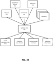
- a set of constraints (210, 212, 214, 216, and Scenarios) are provided to a synthesis tool 220.
- the performance and function of the tool 220 may include third-party ASIC implementation tools such as logic synthesis, place and route back end tools, and so on.
- a designer and/or user builds the set of constraints that are provided to the tool 220.
- the constraints are captured in machine-readable form, such as computer files using a defined format to capture information that is understood and processed by the tool.
- the format is XML.
- the format is JSON. The scope of the invention is not limited by the specific format used.
- the tool reads the files containing the description of the constraints and executes the synthesis process.
- the synthesis process is broken down into multiple steps.
- a sequencer 250 is responsible for executing each step of the process.
- a set of steps are executed by the sequencer 250 of the tool 220 in light of the constraints set forth by the user/designer. The scope of the invention is not limited by the number and kind of steps the sequencer 250 may call and execute.
- a sequencer 250 receives various inputs, including: input 251 that includes global consolidation roadmaps with connectivity between initiators and targets including roadmap creation and information between each initiator and target; input 252 that includes traffic classification and main switch creation; input 254 that includes main switch decomposition into mergers and splitters; input 258 that includes information about physical distribution of splitters and mergers in the roadmap; input 259 that includes information about edge clustering; and input 260 that includes information about performance aware node clustering.
- the sequencer 250 also receives input 262 that includes information about optimization and network restructuring. In accordance with one aspect of the invention, the sequencer 250 receives 264 that includes information about routing and legalization. In accordance with various aspects and embodiments of the invention, the sequencer 250 uses all the inputs 251-264 to generate the network. In accordance with various aspects and embodiments of the invention, the sequencer 250 uses a combination of the inputs 251-264 to generate the network.
- input 251 includes input about the global consolidation roadmap.
- the global consolidation roadmap includes a consolidation model that captures the global physical view of the connectivity of the floorplan's free space, as well as the connectivity across/between the initiators and targets.
- the global consolidation roadmap is modeled by a graph of physical nodes and canonical segments that are used to position the nodes (splitters, mergers, switches, adapters) of the network under construction.
- the global consolidation roadmap is used to fasten computation.
- the global consolidation roadmap is persistent, which means that it is data the system exports and re-consumes in incremental synthesis and subsequent runs.
- input 259 includes information about edge clustering.
- Edge clustering aims to minimize resources and enhance performance goals through proper algorithms and techniques.
- edge clustering is applied in conjunction and in cooperation with input 260, node clustering.
- Edge clustering and node clustering can be used in combination by mixing, by being applied concurrently, or by being applied in sequence. The advantage and goal is to expand the spectrum of synthesis and span a larger solution space for the network.
- input 262 includes information about restructuring.
- Re-structuring includes a variety of transformations and capabilities.
- the transformations are logical in that there is a change in structure of the network.
- the transformation is physical because there is a physical change in the network, such as moving a node to a new location.
- Other examples of restructuring include: breaking a node into smaller nodes; reparenting between nodes; network subpart duplication to avoid deadlocks and to deal with congestion; and physically re-routing links to avoid congestion areas or to meet timing constraints.
- another constraint includes extension of the clock domain and power domain 212 can also be provided.
- the domain 212 includes areas of the chip where logic belonging to a particular domain is allowed to be placed.
- a floorplan 300 of the chip onto which the NoC is implemented is shown, with positions for various initiator interfaces and target interfaces.
- the physical constraint 210 provides physical information about the design that includes: the size of the chip onto which the NoC will be implemented; the various blockages areas on the floor plan, which are rectangles representing area of the chip onto which the NoC logic cannot exist or be placed; the free space, which is area of the chip where the NoC logic can exist and is defined by area not covered by a blockage; and the position of the interfaces between the SoC units and the NoC, which is the position of the initiator interfaces and the targets interfaces, such as NIUs.
- the blockages may be represented at the top level of the floorplan, or they may be contained in a hierarchical representation of the physical/logical blocks within the design and are then used at the top level in the same fashion.
- the information includes the size of a reference logic gate, and the time it takes for a signal to cover a 1 mm distance.
- a SoC includes multiple clock domains and multiple power domains.
- a clock domain is defined by all the logic fed by a given clock input.
- the clock input is characterized by the frequency of the clock, which is its most important parameter.
- a power domain is defined by all the logic getting power supply from the same power source.
- the power source is gated, thus, the power domain can be on or off or isolated from other power domains.
- the designer provides the set of clock domain and power domain constraints 212 as part of the initial design.
- initiators and targets are communicatively connected to the NoC.
- An initiator is a unit that sends requests.
- An initiator typically is configured to read and write commands.
- a target is a unit that serves or responds to the requests.
- a target typically is configured to read and write commands.
- Each initiator is attached to or connected to the NoC through a NIU.
- the NIU that is attached to an initiator is called an Initiator Network Interface Unit (INIU).
- IIU Initiator Network Interface Unit
- each target is attached to the NoC through an NIU.
- the NIU that is attached to a target is called a Target Network Interface Unit (TNIU).
- TNIU Target Network Interface Unit
- the primary functionality of the NoC is to carry each request from an initiator to the desired destination target, and if the request demands or needs a response, then the NoC carries each target's response to the corresponding requesting initiator.
- Initiators and targets have many different parameters that characterize them.
- the clock domain and power domain they belong to are defined for each initiator and target.
- the width of the data bus they use to send, write, and receive read payloads is a number of bits.
- the width of the data bus for the connection (the communication path to/from a target) used to send, write requests, and receive write responses are also defined.
- the clock and power domain definition are a reference to the previously described clock and power domains existing in the SoC, as described herein.
- a connectivity table 400 is shown.
- the table 400 allows for traffic to be defined by classification.
- the tool permits using a traffic class label for each connection between an initiator and a target.
- a traffic class label is an arbitrary label, chosen by the user or designer. Any number of labels can be defined and the scope of the invention is not limited by the number of labels.
- Each label represents the need for independent network resources.
- Each label will be given a distinct sub-network by the invention, which can be physically different, or use virtual networks, if supported by the underlying NoC technology.
- initiators are not required to be able to send requests to all targets or targets that are connected to the NoC.
- the precise definition of the target that can receive requests from an initiator is outlined or set forth in the connectivity table, such as table 400.
- the connectivity and traffic class labeling information can be represented as an explicit or conceptual matrix. Each initiator has a row and each target has a column. If an initiator must be able to send traffic to a target, a traffic class label must be present at the intersection between the initiator row and the target column. If no label is present at an intersection, then the tool does not need connectivity between that initiator and that target.
- initiator 1 is connectively communicating with target 1 (S1) using a defined label 1 (L1) while M1 does not communicate with S2 and hence there is no label in the intersection of M1 and S2.
- the actual format used to represent connectivity can be different, as long as each pair of initiator-target combination has a precise definition of its traffic class, or no classification label if there is no connection. It is within the scope of this invention for an initiator/target connection to support a plurality of traffic classes.
- a table 500 is shown in accordance with the various aspects of the invention, that includes various scenarios (shown in FIG. 2A ) for read (RD) and write (WR) transactions.
- the table 500 includes information that define the various throughput rates provided to the tool.
- a scenario defines the expected performance in terms of throughput of data between an initiator and a target.
- Each scenario describes the expected required read bandwidth and the expected required write bandwidth between each initiator and each target.
- Throughput is defined in bytes-per-second (B/s).
- a typical SoC will have multiple modes of operations.
- a SoC for a smartphone might have a gaming mode of operation, an audio call mode of operation, an idle mode of operation and so on.
- a set of scenarios represents the different modes of operation the SoC supports and, correspondingly, the expected NoC minimum performance in terms of throughput between initiators and targets.
- a scenario can be represented as 2 matrixes, one defining read throughputs and one defining write throughputs.
- read throughput requirements will be used to size the response network, which handles data returning from targets back to the initiator.
- Write throughput requirements will be used to size the request network, which is data going from initiator to target, in accordance with the various aspects of the invention.
- An example, in accordance with the various aspects of the invention, of the throughput requirements for the various scenarios is shown in table 500.
- the actual format used to represent a scenario can be different, as long as each pair of (initiator, target) has a precise definition of its minimum required throughput for read and for write.
- read transaction from M1 to S1 has a minimum performance throughput of 100MB/s.
- a write transaction from M1 to S1 has a minimum throughput of 50 MB/s.
- latency refers to the number of clock cycles it takes for data to make its way through the network. Latency causes problems in transport networks despite having a high-bandwidth (frequency).
- An example of a "real-time traffic class" would be video data from a camera in a self-driving car. It isn't acceptable to have long latency in the propagation of the data. If some data were lost it would make the vehicle unsafe. A still real-time but less vital traffic class would be for audio and/or video in the entertainment system. It would not be desirable to have a gap in that data, but not unsafe.
- An example of non-real-time data would be data from a gas gauge sensor in a car. If the data is delayed for several seconds, it is of no matter since the rate of change of the data is quite slow compared to the operating speed of an SoC.
- scenarios are not defined for the tool, in which case the tool optimizes the NoC synthesis process for physical cost, such as lowest gate cost and/or lowest wire cost.
- an initial network 600 is created in accordance with the various aspects of the invention.
- the network 600 implements the connectivity matrix with the following defined parameter or components:
- each switch, and the clock domain it belongs to is computed using the data width of each attached interface, and their clock domain, as inputs to the tool.
- each step that transforms the network, which is part of the NoC also performs the computation of the data width and the clock domain of the newly created network elements.
- the network 600 of FIG. 6 is shown wherein the tool's process transforms the network 600 in accordance with the various aspects of the invention.
- the sequencer 250 has an input 254 representing the main switch decomposition into mergers and splitters.
- the tool decomposes each main switch of the network 600 into its equivalent implementation with splitters and mergers.
- some switches have a single ingress port and multiple egress ports.
- some switches have multiple ingress ports and a single egress port.
- Each main switch ingress port is connected to a splitter, each main switch egress port is connected to a merger.
- splitters and mergers are connected together according to the connectivity table.
- the sequencer 250 has an input 256 representing a roadmap creation between each initiator and target.
- the floorplan 800 includes a physical path 802 that is computed between an initiator interface (M0) on the floor plan, and each of its connected targets, such as target S0, target S1, target S2, and target S3.
- the path 802 is called the splitter roadmap of the initiator M0; while not shown, every initiator will have a splitter roadmap.
- the tool uses any algorithm suitable for finding a path between a source point and multiple destination points, including algorithms that minimize the length of the paths.
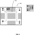
- the floorplan 800 has computed a physical path 902 between a target interface for the target S0 on the floorplan and each of its connected initiators.
- the path 902 is a merger roadmap of the target S0.
- every target will have a merger roadmap.
- the tool uses any algorithm suitable to finding a path between multiple source points and a destination point can be used, including algorithms that minimize the length of the paths.
- the tool transforms the network in a way that maintains its functionality and adds location information to the network elements.
- the sequencer 250 has an input 258 that provides physical distribution of splitters and mergers on the roadmap.
- each switch is decomposed into mergers and splitters.
- each splitter in the main switch is decomposed further into a cascade of splitters and each splitter of the cascade being placed on a branching point of the splitter roadmap of the attached initiator.
- the branching point of the roadmap is defined by the fact that the path is being split into two or more branches.
- each switch for each of the mergers in the main switch is decomposed further into a cascade of mergers, each merger of the cascade being placed on a branching point of the merger roadmap of the attached target.
- the branching point of the roadmap is defined by the fact that the path is being split into two or more branches.
- the process of decomposing a merger in a cascade of mergers preserves the original merger functionality, as the number of outputs of the cascade is still one, and the number of inputs to the cascade is identical to the number of inputs to the original merger.
- the effect of the process is to obtain a set of elementary switches, which are represented by the mergers and the splitters, that are physically placed close to where the actual connections between switches need to be.
- the tool transforms the network in order to reduce the number of wires used between switches achievable, while keeping the performance as defined in the scenarios, which are a set of required minimum throughput between initiator and target.
- switches are clustered for performance aware switching, mergers and splitters that have been distributed on the roadmaps are treated like ordinary switches.
- the tool uses a process that is iterative and will merge switches under the condition that performances are still met, until no further switch merge can occur.
- the tool uses a process that is described as follows:
- the process it is possible for the process to ensure the switches do not grow above a certain size (maximum number of ingress ports, maximum number of egress ports). If a combined switch is above the set threshold, then the merge is prevented.
- candidate switch SW3 is shown next to switch SW4 for the merger, in accordance with the various aspects of the invention.
- the sequencer 250 has an input 260 that provides performance aware switching clustering.
- the tool executes a process for merging two switches. When the switches are merged, the wires that were going from different switches are simplified into one wire from each connected switch to the combined switch.
- switches SW3 and SW4 are merged.
- the connections between SW1 and SW4 and SW3 are combined and replaced by a single connection between SW1 and SW3_4.
- an input 262 to the sequencer 250 includes various optimizations that can be performed to further reduce the number of wires used by the network, the area of the network elements, and the power consumed by network elements.
- optimizations include: detection of links that can be removed because they are not used, or their traffic can be re-routed; reducing the width of a link if the link is wider than required by the scenarios; and performing wire length optimization through finding an optimal placement of all the switch elements that minimizes the total wire length of the network, wherein the total wire length of the network is the sum of the distance spanned by each connection between network elements times the width of that connection.
- an input 264 to the sequencer 250 includes producing a legal NoC by modifying the location of the network elements so that the network elements fit in the allocated free space and do not overlap, and they exist in the corresponding clock and power domain limits.
- the area occupied on the die by each network element is computed using the information provided regarding the capabilities of the technology, such as the area of a reference logic gate. Then each element is tested for correctness of its placement (enough free space exists for the element, no other element overlaps). If the test fails, the element is moved until a suitable location is found where the test passes.
- extension of clock and power domains on the floorplan are provided and each element is tested to ensure it is located within the bounds of the specified clock and power domain. If the test fails, the element is moved until a suitable location is found where the test is passing. Once a suitable placement has been found for each element, a routing is done of each connection between elements. The routing process will find a suitable path for the set of wires making the connections between elements. After routing is done, distance-spanning pipeline elements are inserted on the links if required, using the information provided regarding the capabilities of the technology, based on how long it takes for a signal to cover a 1 mm distance.
- the tool generates one or more computer files describing the generated NoC that includes:
- the tool is used to generate metrics about the generated NoC, such as: histograms of wire length distribution, number of switches, histogram of switch by size.
- the tool automatically inserts in the network various adapters and buffers.
- the tool inserts the adapters based on the adaptation required between two elements that have different data width, different clock and power domains.
- the tool inserts the buffers based on the scenarios and the detected rate mismatch.
- the tool can be used to ensure multiple iterations of the synthesis are done for incremental optimization of the NoC, which includes a situation when one constraint provided to the tool is information about the previous run.
- the results are produced in a machine-readable form, such as computer files using a well-defined format to capture information.
- a machine-readable form such as computer files using a well-defined format to capture information.
- An example of such a format is XML, another example of such a format is JSON.
- the scope of the invention is not limited by the specific format.
- FIG. 13 shows a method 1300 executed by a tool that enhances a synthesized NoC with data that acts as guidance for the physical implementation of the synthesized NoC.
- a constraint parameter for the network is received at the tool, wherein the constraint parameter is selected from a group of constraints, which at least includes physical constraints and performance constraints.
- the physical floor plan of the NoC is augmented with additional information to help guide the physical implementation. For example, information may be related to placeholders for potential pipelines in the physical floorplan.
- the tool constraints based on the augment information added to or for the physical floorplan, a physical implementation of a connection to a location on the physical floorplan within the constraint parameter.
- a gate of the connection is oriented, using the tool, at a shortest routing distance from the connection compared to a listing of routing distances between the gate and the connection detected by the tool.
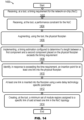
- FIG. 14 shows a flow chart illustrating an alternate method 1400 used by a tool for creating a synthesized NoC with data indicating potential guidance for the physical implementation.
- the tool receives a timing requirement for the NoC.
- the tool receives performance constraints for the NoC.
- the tool augments the NoC's physical floorplan with information that can be used to guide the implementation of the synthesized NoC.
- the tool implements a timing estimation configured to determine if a length between a first component and a second component placed on the physical floorplan exceeds the timing requirement (timing constraints).
- the tool in response to exceeding the time requirement, identifies a physical insertion point for at least one link into the physical floorplan.
- At step 1412 at least one link is inserted into the floorplan using a wire delay technology specific parameter in accordance with some aspects and embodiments of the invention.
- the tool identifies a minimum set of module regions that can be assigned to a specific link of said at least one link of the NoC topology.
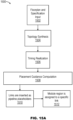
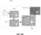
- FIGS. 15A and 15B show the process used by the tool of FIG. 13 and FIG. 14 for physically implementing the synthesized NoC's topology in accordance with various aspects of the invention.
- Providing any physical implementation tool including, but not limited to, a Synopsys SNPS Design Compiler, with NoC topology information 1502 including, but not limited to, a physical floorplan, location of components, and/or specification input.
- Routes are produced by topology synthesis (also called NoC generation) 1504 and are configured to traverse through a set of floor plan regions or checkpoints.
- Mechanism 1506, includes, but is not limited to, a timing realization such as, a distance pipe insertion configured to improve timing between two components.
- the insertion 1510 of distance pipeline placeholders may use the wire delay technology-specific parameter to insert placeholders for potential pipelines. Using the method, many segments in the network will fall within the legal length for timing closure. In other words, the length between two components is within parameters established in the timing constraints.
- the placeholder is a regular component of the topology known as a link.
- automatic module region creation 1512 facilitates the creation of a minimum set of module regions that are assigned specific links of the topology.
- the links that were inserted as pipeline placeholders may be reused as checkpoints.
- a new link and corresponding module region is inserted into the physical path when placement guidance computation 1508 detects, based on information 1502, a problem to be avoided.
- a new link and corresponding module region are inserted 1510 and 1512 into the physical topology when a predetermined wire distance is traversed between two hops along both X and Y. In other words, the timing requirement is exceeded because the distance between the two components is too great. This process ensures the downstream tool will route the topology wires approximately following the path of the topology synthesis. Further, since the routing is similar, the pipeline placeholders that the topology synthesis process generated have a high probability of reducing timing violations in the final design.
- a mechanism for accommodating timing realization between a first component and a second component within a NoC includes, but is not limited to, distance pipe insertion, adding buffer stages, switching buffers to higher drive or faster buffers, adjustments to wire widths, and/or indication to which wire layer(s) are being used.
- connection includes, but not be limited to, a physical placement of an object, a component and/or a gate around the NoC topology so that a downstream tool does not place a first connection at a great enough distance away from a second connection, so as to exceed a time restraint. It is more desirable to synthesize a network for all of the connections capable of satisfying connectivity requirements and to minimize the number of gates in the synthesized network.
- components of the driving side are replaced with components having greater drive strength to increase speed.
- a distance pipe may be placed in between the first switch and the second switch or the drive strength may be increased to make the signal faster by using larger wires having a lower resistance to reduce the parasitic elements on the particular line.
- a floorplan region is a mechanism capable of including, but not limited to; constraining a component, such as a switch and/or a distance pipe stage to a physical location and/or an approximate physical location; and/or dividing a logical interconnect into a plurality of portions that are tuned to the size of the downstream tools for proper synthesis.
- the physical and logical configuration of the interconnects are configured together to form a logical interconnect.
- the floorplan regions are used to constrain a component to a particular location.
- the need for a floorplan region is a response to the increasing size of the network or interconnect of SoCs that are being developed. In other words, the network or interconnect of SoCs have grown larger than downstream implementation tools capacity including, but not limited to, the addition of wider interconnects and/or more components being interconnected.
- an additional constraint may be utilized to place, for example, gates of a component for a switch or a pipe stage, as close together as possible within each individual component.
- a current problem in existing placement programs is their tendency to place components too far away from each other. It is within the scope of this invention for a switch being a single component having a plurality of gates, with each gate having a need to be placed.
- the netlist facilitates the interconnection of these components, the downstream tools physically place the components and make the routes to connect the logical connectivity specified.
- the two separate constraints of the first aspect and the second aspect may be used simultaneously. For example, if a switch that is specified to have a particular performance has the components of that switch distributed over a larger area than specified, the switch will have a lower performance than originally specified. Thus, it would be more desirable to keep components of this switch close together, to each other. Further, based on a larger network, it is more desirable to keep components within a particular region or area of the floorplan free space so that the overall network will perform as specified or analyzed.
- a maximum length of a single wire is established to ensure that the overall timing of that particular path can be met. Further, it is an important aspect to move from a first component to a second component within a given amount of time. Due to an excessive length between a first component and a second component it may not be achievable to move a signal from the first component to the second component within the given amount of time. As a result, the need for the technical solution of an insertion of distance pipe stages would solve this technical problem, as compared to current techniques.
- a method for guiding physical generation of a NoC from a synthesized representation. The includes receiving, at a tool, at least one constraint parameter for the NoC, the at least one constraint parameter is selected from a group of constraint parameters including at least one physical constraint and at least one performance constraint; augmenting, using the tool, a physical floorplan for the NoC with information that guides a physical implementation of the NoC; and constraining, using the physical floorplan, the physical implementation of a connection to a location on the physical floorplan based on the at least one constraint parameter.
- a method is disclosed wherein a gate of the connection is oriented, using the tool, at a shortest routing distance from the connection compared to a listing of routing distances between the gate and the connection detected by the tool.
- a method includes dividing, using the tool, a logical interconnect into a plurality of portions, whereby, the plurality of portions of the logical interconnect are calibrated to a size of the tool.
- a method for guiding a physical implementation of a synthesized topology of a NoC.
- the method includes receiving, at a tool, at least one timing requirement for the NoC; receiving, at the tool, at least one performance constraint for the NoC; augmenting, using the tool, a physical floorplan for the NoC with information to guide the physical implementation; implementing a timing estimation configured to determine if a length between a first component and a second component placed on the physical floorplan exceeds the at least one timing requirement; and inserting, in response to exceeding the at least one timing requirement, at least one link in the physical floorplan.
- a method is disclosed, wherein the at least one link is inserted using a wire delay technology-specific parameter. In accordance with some aspects and embodiments of the invention, a method is disclosed further comprising creating, at the tool, at least one module region, wherein the at least one link of the NoC is assigned to the at least one module region.
- a method includes receiving an area-estimation for the first component and the second component.
- a method includes performing a balance to the at least one timing requirement in an optimization of the NoC to identify that at least one gate of the NoC can be placeable into at least a portion of the physical floorplan.
- a method includes performing a balance to the at least one performance constraint in an optimization of the NoC to identify that at least one gate of the NoC can be placeable into at least a portion of the physical floorplan.
- a method includes receiving a power requirement for the NoC.
- a method includes performing a balance to the at least one timing requirement in an optimization of the NoC to identify that the NoC will not exceed the power requirement specified in the at least one timing requirement.
- a method includes performing a balance to the at least one performance constraint in an optimization of the NoC to identify that the NoC will not exceed the power requirement specified in the at least one performance constraint.
- a method is disclosed that includes providing physical routing congestion data.
- a method includes performing a balance to the at least one timing requirement in an optimization of the NoC to identify that the NoC can be routable into at least a portion of the physical floorplan.
- a method includes performing a balance to the at least one performance constraint in an optimization of the NoC to identify that at least one gate of the NoC can be routable into at least a portion of the physical floorplan.
- Non-transitory computer readable medium stores code including instructions that, if executed by one or more processors, would cause a system or computer to perform steps of the method described herein.
- the non-transitory computer readable medium includes: a rotating magnetic disk, a rotating optical disk, a flash random access memory (RAM) chip, and other mechanically moving or solid-state storage media. Any type of computer-readable medium is appropriate for storing code comprising instructions according to various examples.
- IP elements or units include: processors (e.g., CPUs or GPUs), RAM - e.g., off-chip dynamic RAM or DRAM, a network interface for wired or wireless connections such as ethernet, Wi-Fi, 3G, 4G long-term evolution (LTE), 5G, and other wireless interface standard radios.
- the IP may also include various I/O interface devices, as needed for different peripheral devices such as touch screen sensors, geolocation receivers, microphones, speakers, Bluetooth peripherals, and USB devices, such as keyboards and mice, among others.
- processors e.g., CPUs or GPUs
- RAM - e.g., off-chip dynamic RAM or DRAM
- the IP may also include various I/O interface devices, as needed for different peripheral devices such as touch screen sensors, geolocation receivers, microphones, speakers, Bluetooth peripherals, and USB devices, such as keyboards and mice, among others.
- Some examples are one or more non-transitory computer readable media arranged to store such instructions for methods described herein. Whatever machine holds non-transitory computer readable media comprising any of the necessary code may implement an example. Some examples may be implemented as: physical devices such as semiconductor chips; hardware description language representations of the logical or functional behavior of such devices; and one or more non-transitory computer readable media arranged to store such hardware description language representations. Descriptions herein reciting principles, aspects, and embodiments encompass both structural and functional equivalents thereof. Elements described herein as coupled have an effectual relationship realizable by a direct connection or indirectly with one or more other intervening elements.
Landscapes
- Engineering & Computer Science (AREA)
- Computer Hardware Design (AREA)
- Theoretical Computer Science (AREA)
- Physics & Mathematics (AREA)
- General Engineering & Computer Science (AREA)
- General Physics & Mathematics (AREA)
- Evolutionary Computation (AREA)
- Geometry (AREA)
- Microelectronics & Electronic Packaging (AREA)
- Computing Systems (AREA)
- Computer Networks & Wireless Communication (AREA)
- Human Computer Interaction (AREA)
- Manufacturing & Machinery (AREA)
- Automation & Control Theory (AREA)
- Architecture (AREA)
- Data Exchanges In Wide-Area Networks (AREA)
- Design And Manufacture Of Integrated Circuits (AREA)
- Information Retrieval, Db Structures And Fs Structures Therefor (AREA)
Applications Claiming Priority (1)
| Application Number | Priority Date | Filing Date | Title |
|---|---|---|---|
| US18/305,382 US20240353813A1 (en) | 2023-04-24 | 2023-04-24 | Process for generating physical implementation guidance during the synthesis of a network-on-chip |
Publications (2)
| Publication Number | Publication Date |
|---|---|
| EP4455929A2 true EP4455929A2 (de) | 2024-10-30 |
| EP4455929A3 EP4455929A3 (de) | 2024-12-04 |
Family
ID=90880605
Family Applications (1)
| Application Number | Title | Priority Date | Filing Date |
|---|---|---|---|
| EP24172264.4A Pending EP4455929A3 (de) | 2023-04-24 | 2024-04-24 | Verfahren zur erzeugung einer physischen implementierungsführung während der synthese eines netzwerks auf einem chip |
Country Status (5)
| Country | Link |
|---|---|
| US (1) | US20240353813A1 (de) |
| EP (1) | EP4455929A3 (de) |
| JP (1) | JP2024156647A (de) |
| KR (1) | KR20240156976A (de) |
| CN (1) | CN118838864A (de) |
Family Cites Families (3)
| Publication number | Priority date | Publication date | Assignee | Title |
|---|---|---|---|---|
| US11121933B2 (en) * | 2019-12-27 | 2021-09-14 | Arteris, Inc. | Physically aware topology synthesis of a network |
| EP4013014A1 (de) * | 2020-12-09 | 2022-06-15 | Arteris, Inc. | Mehrphasige topologiesynthese eines netzwerks auf einem chip (noc) |
| US12524590B2 (en) * | 2021-09-29 | 2026-01-13 | Arteris, Inc. | Synthesis of a network-on-chip (NoC) for insertion of pipeline stages |
-
2023
- 2023-04-24 US US18/305,382 patent/US20240353813A1/en active Pending
-
2024
- 2024-04-24 EP EP24172264.4A patent/EP4455929A3/de active Pending
- 2024-04-24 KR KR1020240054719A patent/KR20240156976A/ko active Pending
- 2024-04-24 CN CN202410500666.7A patent/CN118838864A/zh active Pending
- 2024-04-24 JP JP2024070717A patent/JP2024156647A/ja active Pending
Also Published As
| Publication number | Publication date |
|---|---|
| JP2024156647A (ja) | 2024-11-06 |
| US20240353813A1 (en) | 2024-10-24 |
| KR20240156976A (ko) | 2024-10-31 |
| CN118838864A (zh) | 2024-10-25 |
| EP4455929A3 (de) | 2024-12-04 |
Similar Documents
| Publication | Publication Date | Title |
|---|---|---|
| US12237980B2 (en) | Topology synthesis of a network-on-chip (NoC) | |
| US11784909B2 (en) | Quality metrics for optimization tasks in generation of a network | |
| US20250174294A1 (en) | TOOL FOR FAULT DETECTION AND CLASSIFICATION IN DESIGN AND GENERATION OF NETWORK-ON-CHIP (NoCs) | |
| US20240427978A1 (en) | Tool for supporting use of regular network topologies in generating a network-on-chip topology | |
| EP4404097B1 (de) | System und verfahren zur deterministischen und inkrementellen physikalisch bewussten netzwerk-on-chip-erzeugung | |
| EP4455929A2 (de) | Verfahren zur erzeugung einer physischen implementierungsführung während der synthese eines netzwerks auf einem chip | |
| US20250117355A1 (en) | SYSTEM AND METHOD FOR GENERATION OF NETWORKS-ON-CHIP (NoCs) | |
| EP4471653A1 (de) | Entwurfswerkzeug zur inkrementellen platzierung von elementen auf einem grundriss eines noc | |
| EP4535223A1 (de) | Werkzeug zur fehlererkennung und -klassifizierung beim entwurf und bei der erzeugung von netzwerken auf einem chip (nocs) | |
| US20250117566A1 (en) | SYSTEM AND METHOD FOR GENERATION OF NETWORKS-ON-CHIP (NoCs) USING INCREMENTAL TOPOLOGY SYNTHESIS FOR OPTIMIZATION OF SWITCHES | |
| US20250335690A1 (en) | Design tool using machine learning models for interactive route determination in a network-on-chip | |
| US20260004044A1 (en) | Design tool for generation of a network-on-chip (noc) including insertion of adapters in a path | |
| EP4535222A1 (de) | System und verfahren zur erzeugung von netzwerken auf einem chip (nocs) unter verwendung inkrementeller topologiesynthese zur optimierung von schaltern | |
| EP4492278A1 (de) | Werkzeug zur unterstützung der verwendung regulärer netzwerktopologien bei der erzeugung einer netzwerk-on-chip-topologie | |
| JP2024173806A (ja) | フロアプラン上の要素の対話的な増加配置のための設計ツール | |
| JP2024173814A (ja) | 自動配置制約生成、自動アダプタ挿入処理、局所的および大域的な輻輳捕捉のための設計ツール | |
| JP2024173785A (ja) | フロアプランにおける対話的ワイヤルーティング |
Legal Events
| Date | Code | Title | Description |
|---|---|---|---|
| PUAI | Public reference made under article 153(3) epc to a published international application that has entered the european phase |
Free format text: ORIGINAL CODE: 0009012 |
|
| STAA | Information on the status of an ep patent application or granted ep patent |
Free format text: STATUS: THE APPLICATION HAS BEEN PUBLISHED |
|
| AK | Designated contracting states |
Kind code of ref document: A2 Designated state(s): AL AT BE BG CH CY CZ DE DK EE ES FI FR GB GR HR HU IE IS IT LI LT LU LV MC ME MK MT NL NO PL PT RO RS SE SI SK SM TR |
|
| PUAL | Search report despatched |
Free format text: ORIGINAL CODE: 0009013 |
|
| AK | Designated contracting states |
Kind code of ref document: A3 Designated state(s): AL AT BE BG CH CY CZ DE DK EE ES FI FR GB GR HR HU IE IS IT LI LT LU LV MC ME MK MT NL NO PL PT RO RS SE SI SK SM TR |
|
| RIC1 | Information provided on ipc code assigned before grant |
Ipc: G06F 119/06 20200101ALN20241031BHEP Ipc: G06F 119/12 20200101ALN20241031BHEP Ipc: G06F 115/08 20200101ALN20241031BHEP Ipc: G06F 115/02 20200101ALN20241031BHEP Ipc: G06F 30/398 20200101ALI20241031BHEP Ipc: G06F 30/394 20200101ALI20241031BHEP Ipc: G06F 30/392 20200101AFI20241031BHEP |
|
| STAA | Information on the status of an ep patent application or granted ep patent |
Free format text: STATUS: REQUEST FOR EXAMINATION WAS MADE |
|
| RAP3 | Party data changed (applicant data changed or rights of an application transferred) |
Owner name: ARTERIS, INC. |
|
| 17P | Request for examination filed |
Effective date: 20250604 |