EP4455889A1 - Debugging system and a driver adaptable thereto - Google Patents
Debugging system and a driver adaptable thereto Download PDFInfo
- Publication number
- EP4455889A1 EP4455889A1 EP24150854.8A EP24150854A EP4455889A1 EP 4455889 A1 EP4455889 A1 EP 4455889A1 EP 24150854 A EP24150854 A EP 24150854A EP 4455889 A1 EP4455889 A1 EP 4455889A1
- Authority
- EP
- European Patent Office
- Prior art keywords
- driver
- host
- controller
- general
- output
- Prior art date
- Legal status (The legal status is an assumption and is not a legal conclusion. Google has not performed a legal analysis and makes no representation as to the accuracy of the status listed.)
- Pending
Links
Images


Classifications
-
- G—PHYSICS
- G06—COMPUTING OR CALCULATING; COUNTING
- G06F—ELECTRIC DIGITAL DATA PROCESSING
- G06F11/00—Error detection; Error correction; Monitoring
- G06F11/36—Prevention of errors by analysis, debugging or testing of software
- G06F11/3698—Environments for analysis, debugging or testing of software
-
- B—PERFORMING OPERATIONS; TRANSPORTING
- B60—VEHICLES IN GENERAL
- B60K—ARRANGEMENT OR MOUNTING OF PROPULSION UNITS OR OF TRANSMISSIONS IN VEHICLES; ARRANGEMENT OR MOUNTING OF PLURAL DIVERSE PRIME-MOVERS IN VEHICLES; AUXILIARY DRIVES FOR VEHICLES; INSTRUMENTATION OR DASHBOARDS FOR VEHICLES; ARRANGEMENTS IN CONNECTION WITH COOLING, AIR INTAKE, GAS EXHAUST OR FUEL SUPPLY OF PROPULSION UNITS IN VEHICLES
- B60K35/00—Instruments specially adapted for vehicles; Arrangement of instruments in or on vehicles
-
- G—PHYSICS
- G06—COMPUTING OR CALCULATING; COUNTING
- G06F—ELECTRIC DIGITAL DATA PROCESSING
- G06F13/00—Interconnection of, or transfer of information or other signals between, memories, input/output devices or central processing units
- G06F13/14—Handling requests for interconnection or transfer
- G06F13/20—Handling requests for interconnection or transfer for access to input/output bus
-
- G—PHYSICS
- G06—COMPUTING OR CALCULATING; COUNTING
- G06F—ELECTRIC DIGITAL DATA PROCESSING
- G06F11/00—Error detection; Error correction; Monitoring
- G06F11/22—Detection or location of defective computer hardware by testing during standby operation or during idle time, e.g. start-up testing
- G06F11/2205—Detection or location of defective computer hardware by testing during standby operation or during idle time, e.g. start-up testing using arrangements specific to the hardware being tested
-
- G—PHYSICS
- G06—COMPUTING OR CALCULATING; COUNTING
- G06F—ELECTRIC DIGITAL DATA PROCESSING
- G06F11/00—Error detection; Error correction; Monitoring
- G06F11/22—Detection or location of defective computer hardware by testing during standby operation or during idle time, e.g. start-up testing
- G06F11/26—Functional testing
- G06F11/273—Tester hardware, i.e. output processing circuits
- G06F11/2733—Test interface between tester and unit under test
-
- G—PHYSICS
- G06—COMPUTING OR CALCULATING; COUNTING
- G06F—ELECTRIC DIGITAL DATA PROCESSING
- G06F11/00—Error detection; Error correction; Monitoring
- G06F11/30—Monitoring
- G06F11/34—Recording or statistical evaluation of computer activity, e.g. of down time, of input/output operation ; Recording or statistical evaluation of user activity, e.g. usability assessment
- G06F11/3409—Recording or statistical evaluation of computer activity, e.g. of down time, of input/output operation ; Recording or statistical evaluation of user activity, e.g. usability assessment for performance assessment
- G06F11/3419—Recording or statistical evaluation of computer activity, e.g. of down time, of input/output operation ; Recording or statistical evaluation of user activity, e.g. usability assessment for performance assessment by assessing time
-
- G—PHYSICS
- G06—COMPUTING OR CALCULATING; COUNTING
- G06F—ELECTRIC DIGITAL DATA PROCESSING
- G06F11/00—Error detection; Error correction; Monitoring
- G06F11/36—Prevention of errors by analysis, debugging or testing of software
- G06F11/362—Debugging of software
- G06F11/3636—Debugging of software by tracing the execution of the program
-
- G—PHYSICS
- G06—COMPUTING OR CALCULATING; COUNTING
- G06F—ELECTRIC DIGITAL DATA PROCESSING
- G06F11/00—Error detection; Error correction; Monitoring
- G06F11/36—Prevention of errors by analysis, debugging or testing of software
- G06F11/362—Debugging of software
- G06F11/3644—Debugging of software by instrumenting at runtime
-
- G—PHYSICS
- G06—COMPUTING OR CALCULATING; COUNTING
- G06F—ELECTRIC DIGITAL DATA PROCESSING
- G06F11/00—Error detection; Error correction; Monitoring
- G06F11/36—Prevention of errors by analysis, debugging or testing of software
- G06F11/362—Debugging of software
- G06F11/3648—Debugging of software using additional hardware
- G06F11/3656—Debugging of software using additional hardware using a specific debug interface
-
- G—PHYSICS
- G06—COMPUTING OR CALCULATING; COUNTING
- G06F—ELECTRIC DIGITAL DATA PROCESSING
- G06F11/00—Error detection; Error correction; Monitoring
- G06F11/36—Prevention of errors by analysis, debugging or testing of software
- G06F11/3668—Testing of software
- G06F11/3672—Test management
- G06F11/3688—Test management for test execution, e.g. scheduling of test suites
-
- G—PHYSICS
- G06—COMPUTING OR CALCULATING; COUNTING
- G06F—ELECTRIC DIGITAL DATA PROCESSING
- G06F11/00—Error detection; Error correction; Monitoring
- G06F11/36—Prevention of errors by analysis, debugging or testing of software
- G06F11/3668—Testing of software
- G06F11/3672—Test management
- G06F11/3692—Test management for test results analysis
-
- G—PHYSICS
- G06—COMPUTING OR CALCULATING; COUNTING
- G06F—ELECTRIC DIGITAL DATA PROCESSING
- G06F13/00—Interconnection of, or transfer of information or other signals between, memories, input/output devices or central processing units
- G06F13/38—Information transfer, e.g. on bus
- G06F13/42—Bus transfer protocol, e.g. handshake; Synchronisation
- G06F13/4282—Bus transfer protocol, e.g. handshake; Synchronisation on a serial bus, e.g. I2C bus, SPI bus
-
- G—PHYSICS
- G06—COMPUTING OR CALCULATING; COUNTING
- G06F—ELECTRIC DIGITAL DATA PROCESSING
- G06F2213/00—Indexing scheme relating to interconnection of, or transfer of information or other signals between, memories, input/output devices or central processing units
- G06F2213/40—Bus coupling
Definitions
- the present invention generally relates to a debugging system, and more particularly to a debugging system that is adaptable for use with an automotive touchscreen.
- Automotive touchscreens have become increasingly popular as they replace traditional physical buttons in motor vehicles and allow users to control various functions in a car such as navigation, radio, climate and settings in more flexible and versatile manners.
- TDDI touch and display driver integration
- a debugging system includes a driver and a host.
- the driver controls a touchscreen and includes a driver general-purpose input and output (GPIO).
- the host receives a debug log of status messages from the driver and includes a host general-purpose input and output (GPIO).
- the driver GPIO directly transfers the debug log to the host GPIO without handshaking between the driver and the host.
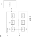
- FIG. 1 shows a block diagram illustrating a debugging system 100 according to one embodiment of the present invention.
- the debugging system 100 of the embodiment may be adaptable for use with an automotive touchscreen that allows users to control various functions in a car such as navigation, radio, climate and settings in automotive applications.
- the debugging system 100 may include a driver 11 configured to control an (automotive) touchscreen 12.
- the driver 11 may include a touch and display driver integration (TDDI) circuit that combines a touch driver and a display driver into one chip for controlling the touchscreen 12, such as an automotive touchscreen in the embodiment.
- TDDI touch and display driver integration
- the driver 11 of the embodiment may include a driver controller 111, such as a microcontroller unit (MCU), designed for embedded applications.
- the driver 11 may include a driver memory device 112, such as a static random-access memory (SRAM), configured to store data received from the driver controller 111 or to be transmitted to the driver controller 111.
- the driver 11 may include a driver general-purpose input and output (GPIO) 113 controlled by the driver controller 111.
- GPIO is a (digital) signal pin on the driver controller 111, and may be controllably used as an input or output.
- the debugging system 100 may include a host 13 (for example, a personal computer) configured to receive a debug log containing status (or error) messages (from the driver 11) that help developers identify and fix errors.
- a host 13 for example, a personal computer
- the host 13 may be adopted as an automotive system (or application processor, AP) in automotive applications.
- the host 13 of the embodiment may include a host controller 131, such as a microcontroller unit (MCU), designed for embedded applications.
- the host 13 may include a host memory device 132, such as a dynamic random-access memory (DRAM), configured to store data received from the host controller 131 or to be transmitted to the host controller 131.
- the host 13 may include a host general-purpose input and output (GPIO) 133 controlled by the host controller 131.
- GPIO is a (digital) signal pin on the host controller 131, and may be controllably used as an input or output
- the driver GPIO 113 (of the driver 11) may be configured to directly transfer the debug log of status messages to the host GPIO 133 (of the host 13) via a bus in a unidirectional manner (for example, without (prior) handshaking between the driver 11 and the host 13).
- the status messages may be encoded by American Standard Code for Information Interchange (ASCII) encoding that uses eight bits to represent alphabetic characters, numerical digits and symbols.
- ASCII American Standard Code for Information Interchange
- alphabetic character "A” may be represented in ASCII encoding by binary 01000001 (or hexadecimal 41 or decimal 65).
- the driver GPIO 113 and the host GPIO 133 may adopt asynchronous serial communication (without requiring a clock signal for synchronization), such as universal asynchronous receiver-transmitter (UART) protocol, to transfer the status messages from the driver GPIO 113 to the host GPIO 133 one bit by one bit, framed by a start bit and a stop bit. Subsequently, the status messages may then be displayed on the touchscreen 12.
- FIG. 2A shows an exemplary UART data format
- FIG. 2B shows an exemplary waveform for transferring alphabetic character "A" by using UART protocol.
- the status messages may be transferred in UART protocol with different transmission speeds.
- FIG. 2C shows some transmission speeds in baud rate (or bits per second) and associated duration times.
- FIG. 3 shows a block diagram illustrating a debugging system 300 without adopting the scheme of FIG. 1 .
- the inter-integrated circuit (I2C) 331 of the automotive system 33 sends an access command to the inter-integrated circuit (I2C) 311 of the TDDI circuit 31.
- the access command is parsed (or analyzed) by the I2C 311, and is then executed by the microcontroller unit (MCU) 312 of the TDDI circuit 31, thereby transferring a status message to the I2C 331 of the automotive system 33.
- the status message may then be displayed on the touchscreen 32. Accordingly, communication link between the TDDI circuit 31 and the automotive system 33 need be established through exchanging the handshaking signal (or the access command) before transferring each status message.
- the debugging system 100 ( FIG. 1 ) of the embodiment can obtain the debug log of status messages in real time, while the debugging system 300 can only obtain the status messages in a passive manner due to handshaking between the TDDI circuit 31 and the automotive system 33. Further, upon receiving the debug log, the debugging system 100 of the embodiment can remotely detect the bug, if any, and update firmware of the driver 11 if required, thereby accomplishing remote debugging, while the debugging system 300 can only perform on-site debugging.
Landscapes
- Engineering & Computer Science (AREA)
- Theoretical Computer Science (AREA)
- General Engineering & Computer Science (AREA)
- Physics & Mathematics (AREA)
- General Physics & Mathematics (AREA)
- Computer Hardware Design (AREA)
- Quality & Reliability (AREA)
- Chemical & Material Sciences (AREA)
- Combustion & Propulsion (AREA)
- Transportation (AREA)
- Mechanical Engineering (AREA)
- Debugging And Monitoring (AREA)
Abstract
A driver adaptable to a debugging system includes a driver controller, and a driver general-purpose input and output (GPIO) controlled by the driver controller. The driver GPIO directly transfers a debug log of status messages of a touchscreen to a host general-purpose input and output (GPIO) of a host without handshaking between the driver and the host.
Description
- The present invention generally relates to a debugging system, and more particularly to a debugging system that is adaptable for use with an automotive touchscreen.
- Automotive touchscreens have become increasingly popular as they replace traditional physical buttons in motor vehicles and allow users to control various functions in a car such as navigation, radio, climate and settings in more flexible and versatile manners.
- However, electronic systems are more prone to errors and failures than physical buttons and thus require debugging (i.e., finding and resolving bugs or problems that prevent correct operation) to ensure that they are functioning properly and meeting the needs of users. Unfortunately, conventional debugging techniques cannot solve problems in real-time or remotely, especially with respect to the driver such as the touch and display driver integration (TDDI). TDDI is a technology that integrates display drivers and touch controllers into a single chip. In addition to TDDI, there are other technologies that require new debugging approaches. For example, system-on-chip (SoC) devices have become more complex, making it difficult to debug them using traditional methods.
- Therefore, there is a need for a novel scheme that can overcome the drawbacks of conventional debugging techniques that are adaptable for use with an automotive touchscreen.
- In light of the above, it is an objective of the present invention to provide a debugging system that can remotely obtain debug logs of status messages in real-time and remotely perform debugging.
- According to one embodiment, a debugging system includes a driver and a host. The driver controls a touchscreen and includes a driver general-purpose input and output (GPIO). The host receives a debug log of status messages from the driver and includes a host general-purpose input and output (GPIO). The driver GPIO directly transfers the debug log to the host GPIO without handshaking between the driver and the host.
-
-
FIG. 1 shows a block diagram illustrating a debugging system according to one embodiment of the present invention; -
FIG. 2A shows an exemplary UART data format; -
FIG. 2B shows an exemplary waveform for transferring alphabetic character "A" by using UART protocol; -
FIG. 2C shows some transmission speeds in baud rate and associated duration times; and -
FIG. 3 shows a block diagram illustrating a debugging system without adopting the scheme ofFIG. 1 . -
FIG. 1 shows a block diagram illustrating adebugging system 100 according to one embodiment of the present invention. Thedebugging system 100 of the embodiment may be adaptable for use with an automotive touchscreen that allows users to control various functions in a car such as navigation, radio, climate and settings in automotive applications. - The
debugging system 100 may include adriver 11 configured to control an (automotive)touchscreen 12. In the embodiment, thedriver 11 may include a touch and display driver integration (TDDI) circuit that combines a touch driver and a display driver into one chip for controlling thetouchscreen 12, such as an automotive touchscreen in the embodiment. - Specifically, the
driver 11 of the embodiment may include adriver controller 111, such as a microcontroller unit (MCU), designed for embedded applications. Thedriver 11 may include adriver memory device 112, such as a static random-access memory (SRAM), configured to store data received from thedriver controller 111 or to be transmitted to thedriver controller 111. Thedriver 11 may include a driver general-purpose input and output (GPIO) 113 controlled by thedriver controller 111. GPIO is a (digital) signal pin on thedriver controller 111, and may be controllably used as an input or output. - The
debugging system 100 may include a host 13 (for example, a personal computer) configured to receive a debug log containing status (or error) messages (from the driver 11) that help developers identify and fix errors. In the embodiment, thehost 13 may be adopted as an automotive system (or application processor, AP) in automotive applications. - Specifically, the
host 13 of the embodiment may include ahost controller 131, such as a microcontroller unit (MCU), designed for embedded applications. Thehost 13 may include ahost memory device 132, such as a dynamic random-access memory (DRAM), configured to store data received from thehost controller 131 or to be transmitted to thehost controller 131. Thehost 13 may include a host general-purpose input and output (GPIO) 133 controlled by thehost controller 131. GPIO is a (digital) signal pin on thehost controller 131, and may be controllably used as an input or output - According to one aspect of the embodiment, the driver GPIO 113 (of the driver 11) may be configured to directly transfer the debug log of status messages to the host GPIO 133 (of the host 13) via a bus in a unidirectional manner (for example, without (prior) handshaking between the
driver 11 and the host 13). - In one embodiment, the status messages may be encoded by American Standard Code for Information Interchange (ASCII) encoding that uses eight bits to represent alphabetic characters, numerical digits and symbols. For example, alphabetic character "A" may be represented in ASCII encoding by binary 01000001 (or hexadecimal 41 or decimal 65).
- In the embodiment, the
driver GPIO 113 and thehost GPIO 133 may adopt asynchronous serial communication (without requiring a clock signal for synchronization), such as universal asynchronous receiver-transmitter (UART) protocol, to transfer the status messages from thedriver GPIO 113 to thehost GPIO 133 one bit by one bit, framed by a start bit and a stop bit. Subsequently, the status messages may then be displayed on thetouchscreen 12.FIG. 2A shows an exemplary UART data format, andFIG. 2B shows an exemplary waveform for transferring alphabetic character "A" by using UART protocol. - In the embodiment, the status messages may be transferred in UART protocol with different transmission speeds.
FIG. 2C shows some transmission speeds in baud rate (or bits per second) and associated duration times. -
FIG. 3 shows a block diagram illustrating adebugging system 300 without adopting the scheme ofFIG. 1 . In operation, the inter-integrated circuit (I2C) 331 of theautomotive system 33 sends an access command to the inter-integrated circuit (I2C) 311 of theTDDI circuit 31. Next, the access command is parsed (or analyzed) by theI2C 311, and is then executed by the microcontroller unit (MCU) 312 of theTDDI circuit 31, thereby transferring a status message to theI2C 331 of theautomotive system 33. The status message may then be displayed on thetouchscreen 32. Accordingly, communication link between theTDDI circuit 31 and theautomotive system 33 need be established through exchanging the handshaking signal (or the access command) before transferring each status message. - Compared to the debugging system 300 (
FIG. 3 ), the debugging system 100 (FIG. 1 ) of the embodiment can obtain the debug log of status messages in real time, while thedebugging system 300 can only obtain the status messages in a passive manner due to handshaking between theTDDI circuit 31 and theautomotive system 33. Further, upon receiving the debug log, thedebugging system 100 of the embodiment can remotely detect the bug, if any, and update firmware of thedriver 11 if required, thereby accomplishing remote debugging, while thedebugging system 300 can only perform on-site debugging.
Claims (15)
- A driver (11) adaptable to a debugging system (100), the driver comprising:a driver controller (111); anda driver general-purpose input and output (113) controlled by the driver controller;wherein the driver general-purpose input and output directly transfers a debug log of status messages of a touchscreen (12) to a host general-purpose input and output (133) of a host (13) without handshaking between the driver and the host.
- The driver of claim 1, further comprising a touch and display driver integration circuit.
- The driver of claim 1, wherein the touchscreen comprises an automotive touchscreen.
- The driver of claim 1, further comprising:
a driver memory device (112) that stores data received from the driver controller or to be transmitted to the driver controller. - The driver of claim 1, wherein the host comprises:a host controller (131); anda host memory device (132) that stores data received from the host controller or to be transmitted to the host controller.
- The driver of claim 1, wherein the status messages are encoded by American Standard Code for Information Interchange encoding.
- The driver of claim 1, wherein the driver general-purpose input and output and the host general-purpose input and output adopt asynchronous serial communication.
- The driver of claim 7, wherein the asynchronous serial communication adopts universal asynchronous receiver-transmitter protocol.
- A debugging system (100), comprising:a driver (11) that controls a touchscreen (12), the driver including a driver general-purpose input and output (113); anda host (13) that receives a debug log of status messages from the driver, the host including a host general-purpose input and output (133);wherein the driver general-purpose input and output directly transfers the debug log to the host general-purpose input and output without handshaking between the driver and the host.
- The debugging system of claim 9, wherein the driver comprises a touch and display driver integration circuit.
- The debugging system of claim 9, wherein the touchscreen comprises an automotive touchscreen.
- The debugging system of claim 9, wherein the driver comprises:a driver controller (111); anda driver memory device (112) that stores data received from the driver controller or to be transmitted to the driver controller.
- The debugging system of claim 9, wherein the host comprises:a host controller (131); anda host memory device (132) that stores data received from the host controller or to be transmitted to the host controller.
- The debugging system of claim 9, wherein the status messages are encoded by American Standard Code for Information Interchange encoding.
- The debugging system of claim 9, wherein the driver general-purpose input and output and the host general-purpose input and output adopt asynchronous serial communication.
Applications Claiming Priority (1)
| Application Number | Priority Date | Filing Date | Title |
|---|---|---|---|
| US18/141,367 US20240362174A1 (en) | 2023-04-29 | 2023-04-29 | Debugging system and a driver adaptable thereto |
Publications (1)
| Publication Number | Publication Date |
|---|---|
| EP4455889A1 true EP4455889A1 (en) | 2024-10-30 |
Family
ID=89542005
Family Applications (1)
| Application Number | Title | Priority Date | Filing Date |
|---|---|---|---|
| EP24150854.8A Pending EP4455889A1 (en) | 2023-04-29 | 2024-01-09 | Debugging system and a driver adaptable thereto |
Country Status (6)
| Country | Link |
|---|---|
| US (1) | US20240362174A1 (en) |
| EP (1) | EP4455889A1 (en) |
| JP (1) | JP7702002B2 (en) |
| KR (1) | KR20240159653A (en) |
| CN (1) | CN118849770A (en) |
| TW (1) | TW202443395A (en) |
Citations (2)
| Publication number | Priority date | Publication date | Assignee | Title |
|---|---|---|---|---|
| US6145093A (en) * | 1997-06-25 | 2000-11-07 | Digital Electronics Corporation | Debugging method and method of displaying information for data processing for use in programmable display device |
| US20200225296A1 (en) * | 2018-09-19 | 2020-07-16 | Kunshan Go-Visionox Opto-Electronics Co., Ltd. | Display module test platform |
Family Cites Families (8)
| Publication number | Priority date | Publication date | Assignee | Title |
|---|---|---|---|---|
| US6011920A (en) * | 1995-04-05 | 2000-01-04 | International Business Machines Corporation | Method and apparatus for debugging applications on a personality neutral debugger |
| US5978902A (en) * | 1997-04-08 | 1999-11-02 | Advanced Micro Devices, Inc. | Debug interface including operating system access of a serial/parallel debug port |
| JP3562783B2 (en) * | 1997-06-25 | 2004-09-08 | 株式会社デジタル | How to debug a programmable display device |
| US7669186B2 (en) * | 2005-11-16 | 2010-02-23 | Sun Microsystems, Inc. | Debugging applications at resource constrained virtual machines using dynamically installable lightweight agents |
| KR101730781B1 (en) * | 2013-12-12 | 2017-04-26 | 인텔 코포레이션 | Techniques for detecting race conditions |
| US11933843B2 (en) * | 2020-07-17 | 2024-03-19 | Intel Corporation | Techniques to enable integrated circuit debug across low power states |
| CN114327699A (en) * | 2020-10-09 | 2022-04-12 | 艾锐势企业有限责任公司 | Embedded product, method of displaying embedded product information, and computer-readable medium |
| US11841398B2 (en) * | 2021-06-28 | 2023-12-12 | Silicon Motion, Inc. | Method and apparatus and non-transitory computer-readable storage medium for debugging solid-state disk (SSD) device |
-
2023
- 2023-04-29 US US18/141,367 patent/US20240362174A1/en active Pending
-
2024
- 2024-01-08 TW TW113100760A patent/TW202443395A/en unknown
- 2024-01-09 EP EP24150854.8A patent/EP4455889A1/en active Pending
- 2024-01-16 CN CN202410061976.3A patent/CN118849770A/en active Pending
- 2024-02-06 KR KR1020240018304A patent/KR20240159653A/en active Pending
- 2024-02-06 JP JP2024016332A patent/JP7702002B2/en active Active
Patent Citations (2)
| Publication number | Priority date | Publication date | Assignee | Title |
|---|---|---|---|---|
| US6145093A (en) * | 1997-06-25 | 2000-11-07 | Digital Electronics Corporation | Debugging method and method of displaying information for data processing for use in programmable display device |
| US20200225296A1 (en) * | 2018-09-19 | 2020-07-16 | Kunshan Go-Visionox Opto-Electronics Co., Ltd. | Display module test platform |
Non-Patent Citations (2)
| Title |
|---|
| ANONYMOUS: "Press Release | Synaptics Launches New TD7850 Automotive TDDI Solution for Touchscreens up to 15 inches | Synaptics", 6 January 2020 (2020-01-06), pages 1 - 4, XP093173211, Retrieved from the Internet <URL:https://www.synaptics.com/company/news/TD7850> [retrieved on 20240613] * |
| ANONYMOUS: "RFC 8304 - Transport Features of the User Datagram Protocol (UDP) and Lightweight UDP (UDP-Lite)", 28 February 2018 (2018-02-28), pages 1 - 20, XP093174729, Retrieved from the Internet <URL:https://datatracker.ietf.org/doc/html/rfc8304> [retrieved on 20240613] * |
Also Published As
| Publication number | Publication date |
|---|---|
| CN118849770A (en) | 2024-10-29 |
| JP2024160042A (en) | 2024-11-11 |
| TW202443395A (en) | 2024-11-01 |
| KR20240159653A (en) | 2024-11-05 |
| US20240362174A1 (en) | 2024-10-31 |
| JP7702002B2 (en) | 2025-07-02 |
Similar Documents
| Publication | Publication Date | Title |
|---|---|---|
| CN102023954B (en) | Device with multiple I2C buses, processor, system main board and industrial controlled computer | |
| US7529862B2 (en) | System for providing access of multiple data buffers to a data retaining and processing device | |
| EP0196911A2 (en) | Local area networks | |
| EP1877911B1 (en) | I2c slave/master interface enhancement using state machines | |
| CN107066746B (en) | Method for realizing PCA9555 function through CPLD based on I2C interface | |
| WO2022161244A1 (en) | Multi-host arbitration method and apparatus, and readable storage medium | |
| US20040010773A1 (en) | Method and apparatus for displaying debug codes of a baisc input/output system | |
| CN114416453B (en) | Chip hardware debugging method and device based on peripheral interface | |
| CN112639755A (en) | Slave-to-slave direct communication | |
| EP4455889A1 (en) | Debugging system and a driver adaptable thereto | |
| JP2008539644A (en) | I2C slave device with programmable write transaction cycle | |
| CN114124609B (en) | A communication device and communication method based on 1553B bus | |
| CN115129552A (en) | Method, device, equipment and storage medium for monitoring transmission state of I2C bus | |
| CN113867787A (en) | Switching system and method between server network cards | |
| CN112445744A (en) | I2C communication | |
| CN101561663A (en) | Motion control system and control method thereof | |
| CN113656250B (en) | Method for implementing lower computer board card state monitoring technology | |
| EP0303288B1 (en) | Peripheral repeater box | |
| CN110795373A (en) | Method for converting I2C bus into parallel bus, terminal and storage medium | |
| CN222281218U (en) | High-speed communication interface circuit, high-speed SWD communication device | |
| JP7784162B2 (en) | Method for associating panel controls for calibration signals, storage medium, and electronic device | |
| CN119739665B (en) | Server main board, control method and equipment | |
| CN110750471A (en) | Method and terminal for realizing I2S slave computer function based on GPIO | |
| KR100349669B1 (en) | Device having I2C bus for interfacing LCD-button and peripheral system and interfacing method of it | |
| CN119829506A (en) | Single-wire communication method, single-wire communication device, electronic equipment and storage medium |
Legal Events
| Date | Code | Title | Description |
|---|---|---|---|
| PUAI | Public reference made under article 153(3) epc to a published international application that has entered the european phase |
Free format text: ORIGINAL CODE: 0009012 |
|
| STAA | Information on the status of an ep patent application or granted ep patent |
Free format text: STATUS: REQUEST FOR EXAMINATION WAS MADE |
|
| 17P | Request for examination filed |
Effective date: 20240109 |
|
| AK | Designated contracting states |
Kind code of ref document: A1 Designated state(s): AL AT BE BG CH CY CZ DE DK EE ES FI FR GB GR HR HU IE IS IT LI LT LU LV MC ME MK MT NL NO PL PT RO RS SE SI SK SM TR |
|
| STAA | Information on the status of an ep patent application or granted ep patent |
Free format text: STATUS: EXAMINATION IS IN PROGRESS |