EP4455847A1 - Touch sensing apparatus and touch sensing method - Google Patents
Touch sensing apparatus and touch sensing method Download PDFInfo
- Publication number
- EP4455847A1 EP4455847A1 EP22911667.8A EP22911667A EP4455847A1 EP 4455847 A1 EP4455847 A1 EP 4455847A1 EP 22911667 A EP22911667 A EP 22911667A EP 4455847 A1 EP4455847 A1 EP 4455847A1
- Authority
- EP
- European Patent Office
- Prior art keywords
- touch
- group
- line
- touch sensing
- valid
- Prior art date
- Legal status (The legal status is an assumption and is not a legal conclusion. Google has not performed a legal analysis and makes no representation as to the accuracy of the status listed.)
- Pending
Links
Images






Classifications
-
- G—PHYSICS
- G06—COMPUTING OR CALCULATING; COUNTING
- G06F—ELECTRIC DIGITAL DATA PROCESSING
- G06F3/00—Input arrangements for transferring data to be processed into a form capable of being handled by the computer; Output arrangements for transferring data from processing unit to output unit, e.g. interface arrangements
- G06F3/01—Input arrangements or combined input and output arrangements for interaction between user and computer
- G06F3/03—Arrangements for converting the position or the displacement of a member into a coded form
- G06F3/041—Digitisers, e.g. for touch screens or touch pads, characterised by the transducing means
-
- G—PHYSICS
- G06—COMPUTING OR CALCULATING; COUNTING
- G06F—ELECTRIC DIGITAL DATA PROCESSING
- G06F3/00—Input arrangements for transferring data to be processed into a form capable of being handled by the computer; Output arrangements for transferring data from processing unit to output unit, e.g. interface arrangements
- G06F3/01—Input arrangements or combined input and output arrangements for interaction between user and computer
- G06F3/03—Arrangements for converting the position or the displacement of a member into a coded form
- G06F3/041—Digitisers, e.g. for touch screens or touch pads, characterised by the transducing means
- G06F3/0416—Control or interface arrangements specially adapted for digitisers
- G06F3/04166—Details of scanning methods, e.g. sampling time, grouping of sub areas or time sharing with display driving
-
- G—PHYSICS
- G06—COMPUTING OR CALCULATING; COUNTING
- G06F—ELECTRIC DIGITAL DATA PROCESSING
- G06F3/00—Input arrangements for transferring data to be processed into a form capable of being handled by the computer; Output arrangements for transferring data from processing unit to output unit, e.g. interface arrangements
- G06F3/01—Input arrangements or combined input and output arrangements for interaction between user and computer
- G06F3/03—Arrangements for converting the position or the displacement of a member into a coded form
- G06F3/041—Digitisers, e.g. for touch screens or touch pads, characterised by the transducing means
- G06F3/0416—Control or interface arrangements specially adapted for digitisers
-
- G—PHYSICS
- G06—COMPUTING OR CALCULATING; COUNTING
- G06F—ELECTRIC DIGITAL DATA PROCESSING
- G06F3/00—Input arrangements for transferring data to be processed into a form capable of being handled by the computer; Output arrangements for transferring data from processing unit to output unit, e.g. interface arrangements
- G06F3/01—Input arrangements or combined input and output arrangements for interaction between user and computer
- G06F3/03—Arrangements for converting the position or the displacement of a member into a coded form
- G06F3/041—Digitisers, e.g. for touch screens or touch pads, characterised by the transducing means
- G06F3/0416—Control or interface arrangements specially adapted for digitisers
- G06F3/0418—Control or interface arrangements specially adapted for digitisers for error correction or compensation, e.g. based on parallax, calibration or alignment
- G06F3/04186—Touch location disambiguation
-
- G—PHYSICS
- G06—COMPUTING OR CALCULATING; COUNTING
- G06F—ELECTRIC DIGITAL DATA PROCESSING
- G06F3/00—Input arrangements for transferring data to be processed into a form capable of being handled by the computer; Output arrangements for transferring data from processing unit to output unit, e.g. interface arrangements
- G06F3/01—Input arrangements or combined input and output arrangements for interaction between user and computer
- G06F3/03—Arrangements for converting the position or the displacement of a member into a coded form
- G06F3/041—Digitisers, e.g. for touch screens or touch pads, characterised by the transducing means
- G06F3/044—Digitisers, e.g. for touch screens or touch pads, characterised by the transducing means by capacitive means
- G06F3/0446—Digitisers, e.g. for touch screens or touch pads, characterised by the transducing means by capacitive means using a grid-like structure of electrodes in at least two directions, e.g. using row and column electrodes
-
- G—PHYSICS
- G06—COMPUTING OR CALCULATING; COUNTING
- G06F—ELECTRIC DIGITAL DATA PROCESSING
- G06F2203/00—Indexing scheme relating to G06F3/00 - G06F3/048
- G06F2203/041—Indexing scheme relating to G06F3/041 - G06F3/045
- G06F2203/04104—Multi-touch detection in digitiser, i.e. details about the simultaneous detection of a plurality of touching locations, e.g. multiple fingers or pen and finger
Definitions
- the present embodiment relates to a touch sensing apparatus and a touch sensing method.
- a multi-touch may be input in display devices including touch panels so as to increase user convenience and recognize various gestures.
- a display device may determine the two touch areas corresponding to the multi-touch as one touch group. In this case, an error in which the multi-touch is recognized as a single touch may occur in the display device.
- an object of the present embodiment is to provide a technology for quickly and accurately separating a multi-touch in which touch areas are adjacent to each other.
- the present embodiment provides touch sensing apparatus including a touch coordinate calculation circuit that selects a valid touch group including two or more valid touch nodes, of which a touch sensing value is greater than or equal to a first reference value from among a plurality of touch nodes that are areas where the plurality of touch sensors are arranged, classifies the valid touch group into three or more line units in one direction, sums touch sensing values for each of the three or more lines, determines a separation line for separating the valid touch group into a first group and a second group from among the three or more lines by using a sum of each of the three or more lines, separates the valid touch group into the first group and the second group based on the separation line, and calculates touch coordinates of the first group and touch coordinates of the second group.
- the present embodiment provides a touch sensing method of a touch sensing apparatus, the touch sensing method including: selecting a valid touch group including two or more valid touch nodes, of which a touch sensing value is greater than or equal to a first reference value from among a plurality of touch nodes; setting a rectangular analysis area including the valid touch group from among the plurality of touch nodes; classifying the analysis area into three or more line units in one direction; summing touch sensing values for each of the three or more lines; determining a separation line for separating the valid touch group into a first group and a second group from among the three or more lines by using a sum of each of the three or more lines; separating the valid touch group into the first group and the second group, based on the separation line; and calculating touch coordinates of the first group and touch coordinates of the second group.
- a multi-touch may be separated quickly and accurately because valid touch groups are classified into line units and a separation line is determined by summing touch sensing values of each line.
- FIG. 1 is a configuration diagram of a display device according to an embodiment.
- a display device 100 may include a panel 110, a data driver (SDIC: Source Driver Integrated Circuit) 120, a gate driver (GDIC: Gate Driver Integrated Circuit) 130, and a data processor (T -CON: Timing Controller) 140, a touch driver (ROIC: ReadOut Integrated Circuit) 150, and a touch controller (T-MCU: Touch Micro Controller Unit) 160.
- SDIC Source Driver Integrated Circuit
- GDIC Gate Driver Integrated Circuit
- T -CON Timing Controller
- ROIC ReadOut Integrated Circuit
- T-MCU Touch Micro Controller Unit
- one or more of the data driver 120, the gate driver 130, and the data processor 140 may be included in a single integrated circuit. These integrated circuits may be referred to as a display driver IC (DDI).
- DPI display driver IC
- touch driver 150 and the touch controller 160 may be included in a single integrated circuit. These integrated circuits may be referred to as a touch integrated circuit (T-IC).
- T-IC touch integrated circuit
- FIG. 1 illustrates that the data driver 120 and the touch driver 150 are separate from each other, the data driver 120 and the touch driver 150 may be included in a single integrated circuit. These integrated circuits may be referred to as a source read integrated circuit (SRIC).
- SRIC source read integrated circuit
- the touch controller 160 may be referred to as a touch sensing apparatus.
- the T-IC including the touch driver 150 and the touch controller 160 may be referred to as a touch sensing apparatus.
- the data driver 120 may drive a data line DL connected to a pixel P
- the gate driver 130 may drive a gate line GL connected to the pixel P
- the touch driver 150 may drive a touch sensor TS arranged on the panel 110.
- a plurality of data lines DL and a plurality of gate lines GL may be arranged on the panel 110, and a plurality of pixels P may be arranged on the panel 110.
- a plurality of touch sensors TS may be arranged on the panel 110.
- the panel 110 may include a display panel and may further include a touch screen panel (TSP).
- TSP touch screen panel
- the display panel and the touch panel may share some components.
- the touch sensors TS of the touch panel may be used as a common electrode to which a common electrode voltage is supplied from the display panel.
- the data driver 120 may supply a data voltage to the data line DL so as to display an image on each pixel P of the panel 110.
- the data driver 120 may include at least one data driver integrated circuit.
- the at least one data driver integrated circuit may be connected to a bonding pad of the panel 110 by a tape automated bonding (TAB) method or a chip on glass (COG) method, or may be directly formed on the panel 110.
- TAB tape automated bonding
- COG chip on glass
- the data driver 120 may be integrated into the panel 110.
- the data driver 120 may be implemented by a chip on film (COF) method.
- the data driver 120 may receive image data IMG' and a data control signal DCS from the data processor 140.
- the data driver 120 may generate a data voltage and drive each pixel according to a grayscale value of each pixel indicated in the image data.
- the data control signal DCS may include at least one synchronization signal.
- the data control signal DCS may include a vertical synchronization signal VSYNC, a horizontal synchronization signal HSYNC, a time division signal, etc.
- the data driver 120 may divide frames according to the vertical synchronization signal VSYNC and may drive each pixel in sections other than a vertical blank section indicated by the vertical synchronization signal VSYNC.
- the data driver 120 may identify image data for each horizontal line according to the horizontal synchronization signal HSYNC and may supply a data voltage for each horizontal line.
- the data driver 120 may divide a display driving period DP and a touch driving period TP according to the time division signal and may drive each pixel within the display driving period DP.
- a period corresponding to one frame may include one display driving period DP and one touch driving period TP.
- a first frame period may include a first display driving period DP1 and a first touch driving period TP1
- a second frame period may include a second display driving period DP2 and a second touch driving period TP2.
- a third frame period may include a third display driving period DP3 and a third touch driving period TP3.
- the gate driver 130 may supply a scan signal to the gate line GL so as to turn on and off a transistor located in each pixel P.
- the gate driver 130 may be located on only one side of the panel 110 as illustrated in FIG. 1 , or the gate driver 130 may be divided into two parts and located on both sides of the panel 110.
- the gate driver 130 may include at least one gate driver integrated circuit, and the at least one gate driver integrated circuit may be connected to the bonding pad of the panel 110 by a tape automated bonding (TAB) method or a chip on glass (COG) method, or the at least one gate driver integrated circuit may be implemented as a gate in panel (GIP) type and directly formed on the panel 110.
- TAB tape automated bonding
- COG chip on glass
- the gate driver 130 may be integrated into the panel 110.
- the gate driver 130 may be implemented by a chip on film (COF) method.
- the gate driver 130 may receive a gate control signal GCS from the data processor 140.
- the gate control signal GCS may include a plurality of clock signals.
- the gate driver 130 may generate a scan signal by using the clock signals and supply the scan signal to the gate line GL.
- the data processor 140 receives timing signals input from the host 30, such as a vertical synchronization signal Vsync, a horizontal synchronization signal Hsync, a data enable signal, and a main clock MCLK, and may synchronize operation timings of the data driver 120 and the gate driver 130.
- timing signals input from the host 30 such as a vertical synchronization signal Vsync, a horizontal synchronization signal Hsync, a data enable signal, and a main clock MCLK, and may synchronize operation timings of the data driver 120 and the gate driver 130.
- the data processor 140 may receive image data IMG from the host 30 and may convert the image data IMG into image data IMG' in the form that may be processed by the data driver 120. The data processor 140 may output the converted image data IMG' to the data driver 120.
- the touch driver 150 may supply a touch driving signal Tx to the touch sensors TS in the touch driving period (TP in FIG. 2 ) and may receive a response signal Rx from the touch sensors TS.
- the touch driver 150 may generate raw data based on the received response signal Rx.
- the raw data may be transmitted to the touch controller 160.
- the touch controller 160 may define, as a plurality of touch nodes, an area of the panel 110 where the plurality of touch sensors TS are arranged.
- the touch controller 160 may calculate touch coordinates based on the raw data.
- the touch controller 160 may calculate touch coordinates for touch input detected from the touch sensors TS.
- the touch controller 160 may track a relationship between the touch coordinates by assigning a touch ID (IDentity) to the calculated touch coordinates.
- IDentity a touch ID
- the touch controller 160 may quickly and accurately separate the multi-touch even when two touch areas for the multi-touch of the user are adjacent to each other as illustrated in FIG. 6 or 11 .
- FIG. 3 is a configuration diagram of a touch sensing apparatus according to an embodiment.
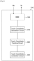
- the touch sensing apparatus may be a touch controller 160, and the touch sensing apparatus, that is, the touch controller 160, may include a touch coordinate calculation circuit 310 and a touch coordinate tracking circuit 320.
- the touch controller 160 may further include a touch coordinate correction circuit 330.
- the touch sensing apparatus may be a T-IC, and the touch sensing apparatus, that is, the T-IC, may further include the touch driver 150 as illustrated in FIG. 4 .
- the touch coordinate calculation circuit 310 may calculate touch coordinates for touch input detected from the touch sensors TS, based on the raw data generated by the touch driver 150.
- the raw data may include touch sensing values detected from each of the plurality of touch sensors TS.
- the raw data may include a touch sensing value for each of a plurality of touch nodes.
- the touch sensing value may be a capacitance value of each touch node.
- the touch coordinate calculation circuit 310 may select a valid touch node, of which a touch sensing value is greater than or equal to a first reference value (e.g., 10) from among the plurality of touch nodes, based on the raw data.
- a first reference value e.g. 10
- the first reference value may be a reference value for determining whether the touch sensing value of the touch node is valid or invalid. For example, when the first reference value is smaller than or equal to the touch sensing value detected at the touch node, an actual touch of the user may have been detected at the touch node, and when the first reference value is greater than the touch sensing value detected at the touch node, noise components, etc. may have been detected at the touch node.
- the touch coordinate calculation circuit 310 may select a valid touch group including the two or more valid touch nodes.
- the touch coordinate calculation circuit 310 may select the valid touch group, of which the touch sensing value is greater than or equal to the first reference value (e.g., 10) from among the plurality of touch nodes, as illustrated in FIG. 6 .
- the first reference value e.g. 10
- two touch areas corresponding to the multi-touch are adjacent to each other.
- an overlapping area is present between a first touch area and a second touch area.
- the touch coordinate calculation circuit 310 has to separate the two touch areas corresponding to the multi-touch from each other and may individually calculate touch coordinates for the first touch area and touch coordinates for the second touch area.
- the touch coordinate calculation circuit 310 may classify the valid touch group into three or more line units in one direction, as illustrated in FIG. 8 .
- the touch coordinate calculation circuit 310 may classify the valid touch group into three or more lines when the number of valid touch nodes included in the valid touch group is greater than or equal to a preset reference number.
- the number of valid touch nodes in the valid touch group corresponding to the multi-touch is greater than the number of valid touch nodes in the valid touch group corresponding to a single touch.
- the valid touch group need not be separated. Therefore, in an embodiment, a reference number may be set so as to determine whether the valid touch group is the multi-touch or the single touch. When the number of valid touch nodes in the valid touch group is greater than or equal to the reference number, the valid touch group is determined to be the multi-touch and is classified into three or more lines.
- the touch coordinate calculation circuit 310 may calculate single touch coordinates for the valid touch group.
- the touch coordinate calculation circuit 310 may set a rectangular analysis area including the valid touch group as illustrated in FIG. 7 .
- the touch coordinate calculation circuit 310 may set the analysis area by using horizontal side start/end information (e.g., c2/c8 in FIG. 7 ) and vertical side start/end information (e.g., r4/r7 in FIG. 7 ) of the valid touch group.
- the touch coordinate calculation circuit 310 may compare the horizontal side length with the vertical side length of the analysis area and may determine a direction corresponding to the shorter side as one direction.
- the touch coordinate calculation circuit 310 may determine the vertical direction of the panel 110 as one direction.
- the touch coordinate calculation circuit 310 which has determined one direction, may classify the valid touch groups into three or more lines in one direction and may sum touch sensing values for each of the three or more lines.
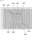
- the touch coordinate calculation circuit 310 may divide the valid touch group into seven lines (LINE1 to LINE7 in FIG. 8 ) corresponding to the vertical direction of the panel 110, as illustrated in FIG. 8 .
- the touch coordinate calculation circuit 310 may sum touch sensing values of (r5,c2) and (r6,c2), which are valid touch nodes included in a first line (LINE1 in FIG. 8 ), and may sum touch sensing values of (r4,c3), (r5,c3), (r6,c3), and (r7,c3), which are valid touch nodes included in a second line (LINE2 in FIG. 8 ).
- the touch coordinate calculation circuit 310 may calculate the sums of a third line (LINE3 in FIG. 8 ) to a seventh line (LINE7 in FIG. 8 ) in the same manner as described above and may calculate the sums (e.g., 47, 131, 96, 51, 98, 150, and 77) of the respective lines.
- the touch coordinate calculation circuit 310 which has calculated the sum of each line, may use the sum of each of the three or more lines to determine a separation line (e.g., the overlapping area in FIG. 6 ) for dividing the valid touch group into a first group (e.g., the first touch area in FIG. 6 ) and a second group (e.g., the second touch area in FIG. 6 ) from among the three or more lines.
- a separation line e.g., the overlapping area in FIG. 6
- a second group e.g., the second touch area in FIG. 6
- the touch coordinate calculation circuit 310 may determine a first highest line with the highest sum on the first group side and a second highest line with the highest sum on the second group side from among the sums of the respective lines as illustrated in FIG. 9 .
- high touch sensing values may be present on both sides (the first group side and the second group side) of the valid touch group.
- the highest lines with the highest sum may be respectively determined on both sides of the valid touch group.
- the touch coordinate calculation circuit 310 may prestore a highest line reference value for determining the highest line and may determine the highest line by comparing the prestored sums of the respective lines with the highest line reference value.
- the first highest line may be the second line LINE2, and the second highest line may be the sixth line LINE6.
- the sum of the first highest line and the sum of the second highest line may correspond to a first crest and a second crest in a sum graph as illustrated in FIG. 9 .
- the separation line corresponding to the overlapping area of the multi-touch may be located between the first highest line and the second highest line, and the sum of the touch sensing values may be smaller than the sum of the first highest line and the sum of the second highest line.
- the touch coordinate calculation circuit 310 may determine a separation line from among one or more lines located between the first highest line and the second highest line.
- the touch coordinate calculation circuit 310 may determine, as the separation line, a line of which the sum is smaller than the sum of the first highest line by a second reference value or more and smaller than the sum of the second highest line by the second reference value or more from among the one or more lines.
- one or more lines may be the third line LINE3 to the fifth line LINES, and when the second reference value is 70, the separation line may be determined to be the fourth line LINE4.
- the touch coordinate calculation circuit 310 may determine, as the separation line, the line with the smallest sum from among the two or more lines.
- the sum of the separation line described above may correspond to a valley in the sum graph as illustrated in FIG. 9 .
- the touch coordinate calculation circuit 310 determines, as the separation line, the line corresponding to the valley from among the respective lines of the valid touch group.
- the touch coordinate calculation circuit 310 which has determined the separation line, may separate the valid touch group into the first group and the second group, based on the separation line.
- the touch coordinate calculation circuit 310 may calculate touch coordinates of the first group and touch coordinates of the second group.
- the touch coordinate calculation circuit 310 may change the touch sensing values of the valid touch nodes corresponding to the separation line to a touch sensing value smaller than the first reference value.
- the touch coordinate calculation circuit 310 may change the valid touch nodes corresponding to the separation line to invalid touch nodes.
- the touch coordinate calculation circuit 310 may select a valid touch group, of which a touch sensing value is greater than or equal to a first reference value from among a plurality of touch nodes, as illustrated in FIG. 11 .
- two touch areas corresponding to the multi-touch are adjacent to each other, and an overlapping area is present between a first touch area and a second touch area.
- the overlapping area may be present in the same diagonal direction as an multi-touch input direction.
- the touch coordinate calculation circuit 310 has to determine, as the diagonal direction of the panel 110, one direction for classifying three or more lines.
- the touch coordinate calculation circuit 310 may set a rectangular analysis area including the valid touch group as illustrated in FIG. 12 and may determine one direction by using touch sensing values of touch nodes ((r3,c4), (r3,c7), (r8,c4), and (r8,c7) in FIG. 12 ) respectively located at four corners of the analysis area.
- the touch coordinate calculation circuit 310 may calculate a first comparison value by summing a touch sensing value of a first touch node ((r3,c4) in FIG. 12 , indicated by a dashed rhombus) located at a first corner and a touch sensing value of a second touch node ((r8,c7) in FIG. 12 , indicated by a dashed rhombus) located at a second corner facing the first corner in a first diagonal direction.
- the touch coordinate calculation circuit 310 may calculate a second comparison value by summing a touch sensing value of a third touch node ((r3,c7) in FIG. 12 , indicated by a dashed circle) located at a third corner and a touch sensing value of a fourth touch node ((r8,c4) in FIG. 12 , indicated by a dashed circle) located at a fourth corner facing the second corner in a second diagonal direction.
- the touch coordinate calculation circuit 310 may compare the first comparison value with the second comparison value and may determine the diagonal direction with the smaller value as one direction.
- the touch coordinate calculation circuit 310 may determine the first diagonal direction, which is an upper left-lower right direction, as one direction.
- the touch coordinate calculation circuit 310 may determine, as one direction, a diagonal direction opposite to the diagonal direction in which the multi-touch is input.
- the touch coordinate calculation circuit 310 may determine the first diagonal direction, which is the diagonal direction opposite to the second diagonal direction, as one direction.
- the touch coordinate calculation circuit 310 which has determined one direction, may classify the valid touch groups into three or more lines in one direction and may sum touch sensing values for each of the three or more lines.
- the touch coordinate calculation circuit 310 may divide the valid touch group into nine lines (LINE1 to LINE9 in FIG. 13 ) corresponding to the first diagonal direction of the panel 110, as illustrated in FIG. 13 .
- the touch coordinate calculation circuit 310 may sum touch a sensing value of (r3,c7), which is a valid touch node included in a first line (LINE1 in FIG. 13 ), and may sum touch sensing values of (r3,c6) and (r4,c7), which are valid touch nodes included in a second line (LINE2 in FIG. 13 ).
- the touch coordinate calculation circuit 310 may calculate the sums of a third line (LINE3 in FIG. 13 ) to a ninth line (LINE9 in FIG. 13 ) in the same manner as described above and may calculate the sums (e.g., 26, 86, 161, 106, 63, 104, 161, 85, and 24) of the respective lines.
- the touch coordinate calculation circuit 310 which has calculated the sum of each line, may use the sum of each of the three or more lines to determine a separation line (e.g., the overlapping area in FIG. 11 ) for dividing the valid touch group into a first group (e.g., the first touch area in FIG. 11 ) and a second group (e.g., the second touch area in FIG. 11 ) from among the three or more lines.
- the sum of each line may form a graph as illustrated in FIG. 14
- the touch coordinate calculation circuit 310 may determine the third line (LINE3 in FIG. 13 ) as the first highest line and may determine the seventh line (LINE7 in FIG. 13 ) as the second highest line.
- the touch coordinate calculation circuit 310 may determine a separation line from among one or more lines located between the first highest line and the second highest line.
- the touch coordinate calculation circuit 310 may determine, as the separation line, a line of which the sum is smaller than the sum of the first highest line by a second reference value or more and smaller than the sum of the second highest line by the second reference value or more from among the one or more lines.
- the touch coordinate calculation circuit 310 may determine, as the separation line, the line with the smallest sum from among the two or more lines.
- the touch coordinate calculation circuit 310 may determine the fifth line (LINES in FIG. 13 ), which is a line corresponding to a valley in FIG. 14 , as the separation line.
- the touch coordinate calculation circuit 310 which has determined the separation line, may separate the valid touch group into the first group and the second group, based on the separation line.
- the touch coordinate calculation circuit 310 may calculate touch coordinates of the first group and touch coordinates of the second group.
- the touch coordinate tracking circuit 320 assigns a touch ID to the touch coordinates calculated by the touch coordinate calculation circuit 310.
- the touch ID may be information for associating the touch coordinates calculated by the touch coordinate calculation circuit 310.
- the touch coordinate tracking circuit 320 may assign, to the touch coordinates of the first group and the touch coordinates of the second group, touch IDs corresponding to the multi-touch.
- the touch coordinate tracking circuit 320 may output the touch coordinates and the touch ID of the first group and the touch coordinates and the touch ID of the second group to the touch coordinate correction circuit 330.
- the touch coordinate correction circuit 330 may correct the touch coordinates output from the touch coordinate tracking circuit 320 by using a smoothing technique.
- the smoothing technique may refer to a technique for reducing noise in touch coordinates.
- the touch coordinates corrected by the touch coordinate correction circuit 330 and the touch ID assigned to the touch coordinates may be output to the host 30.
- the touch coordinates of the first group and the touch ID corresponding to the multi-touch, and the touch coordinates of the second group and the touch ID corresponding to the multi-touch may be output to the host 30.
- the touch sensing apparatus including the touch coordinate calculation circuit 310 classifies the valid touch groups into line units and sums the touch sensing values of the respective lines to determine the separation line, the multi-touch may be separated quickly and accurately.
- a process by which the touch sensing apparatus separates a multi-touch and calculates touch coordinates is described below.
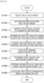
- FIG. 15 is a flowchart showing a process of calculating touch coordinates for a multi-touch in a touch sensing apparatus according to an embodiment.
- the touch sensing apparatus may be the touch controller 160 or may be the T-IC including the touch driver 150 and the touch controller 160.
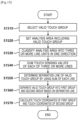
- the touch sensing apparatus may select a valid touch group including two or more valid touch nodes, of which the touch sensing values are greater than or equal to a first reference value from among a plurality of touch nodes, based on raw data (S1510).
- the first reference value may be a reference value for determining whether the touch sensing value of the touch node is valid or invalid.
- the touch sensing apparatus may set a rectangular analysis area including the valid touch group from among the plurality of touch nodes and classify the analysis area into three or more lines in one direction (S1520, S1530).
- the touch sensing apparatus may sum the touch sensing values for each of the three or more lines and then use the sum of each of the three or more lines to determine a separation line for separating the valid touch group into a first group and a second group from among the three or more lines (S1540, S1550).
- the touch sensing apparatus may separate the valid touch group into the first group and the second group, based on the separation line, and may calculate touch coordinates of the first group and touch coordinates of the second group (S1560, S1570).
- the process described above may be more specific depending on the direction of the multi-touch input by the user.
- FIG. 16 is a flowchart showing a process of calculating touch coordinates for a horizontal or vertical multi-touch in a touch sensing apparatus according to an embodiment.
- the touch sensing apparatus may select a valid touch group including two or more valid touch nodes, of which the touch sensing values are greater than or equal to a first reference value from among a plurality of touch nodes, based on raw data (S1610).
- the touch sensing apparatus may set a rectangular analysis area including the valid touch group from among the plurality of touch nodes (S1620).
- the touch sensing apparatus may compare the horizontal side length of the analysis area with the vertical side length of the analysis area and may determine the direction corresponding to the shorter side as one direction (S1630, S1640).
- the touch sensing apparatus may classify the touch sensing values of the valid touch group included in the analysis area into three or more line units in one direction (S1650).
- the touch sensing apparatus may determine the first highest line with the highest sum on the first group side and the second highest line with the highest sum on the second group side from among the three or more lines (S1660, S1670).
- the touch sensing apparatus may determine the separation line by using the first highest line and the second highest line (S1680). In operation S1680, the touch sensing apparatus may determine, as the separation line, a line of which the sum is smaller than the sum of the first highest line by the second reference value or more and smaller than the sum of the second highest line by the second reference value or more from among one or more lines located between the first highest line and the second highest line.
- the touch sensing apparatus may separate the valid touch group into the first group and the second group, based on the separation line, and may calculate touch coordinates of the first group and touch coordinates of the second group (S 1690).
- the touch sensing apparatus may assign, to the touch coordinates of the first group and the touch coordinates of the second group, touch IDs corresponding to the multi-touch.
- the touch sensing apparatus may output, to the host 30, the touch coordinates of the first group, the touch coordinates of the second group, and the touch IDs corresponding to the multi-touch.
- FIG. 17 is a flowchart showing a process of calculating touch coordinates for a diagonal multi-touch in a touch sensing apparatus according to an embodiment.
- the touch sensing apparatus may select a valid touch group including two or more valid touch nodes, of which the touch sensing values are greater than or equal to a first reference value from among a plurality of touch nodes, based on raw data (S1710).
- the touch sensing apparatus may set a rectangular analysis area including the valid touch group from among the plurality of touch nodes (S1720).
- the touch sensing apparatus identify touch nodes located at corners of the analysis area and may determine one direction by using the touch sensing values of the respective touch nodes located at the corners (S1730, S1740).
- the touch sensing apparatus may calculate a first comparison value by summing a touch sensing value of a first touch node located at a first corner of the analysis area and a touch sensing value of a second touch node located at a second corner of the analysis area facing the first corner in a first diagonal direction.
- the touch sensing apparatus may calculate a second comparison value by summing a touch sensing value of a third touch node located at a third corner of the analysis area and a touch sensing value of a fourth touch node located at a fourth corner of the analysis area facing the third corner in a second diagonal direction. Thereafter, the touch sensing apparatus may compare the first comparison value with the second comparison value and may determine the diagonal direction with the smaller value as one direction.
- the touch sensing apparatus may classify the touch sensing values of the valid touch group included in the analysis area into three or more line units in one direction (S1750).
- the touch sensing apparatus may determine the first highest line with the highest sum on the first group side and the second highest line with the highest sum on the second group side from among the three or more lines (S1760, S1770).
- the touch sensing apparatus may determine the separation line by using the first highest line and the second highest line (S1780). In operation S1780, the touch sensing apparatus may determine, as the separation line, a line of which the sum is smaller than the sum of the first highest line by the second reference value or more and smaller than the sum of the second highest line by the second reference value or more from among one or more lines located between the first highest line and the second highest line.
- the touch sensing apparatus may separate the valid touch group into the first group and the second group, based on the separation line, and may calculate touch coordinates of the first group and touch coordinates of the second group (S 1790).
- the touch sensing apparatus may assign, to the touch coordinates of the first group and the touch coordinates of the second group, touch IDs corresponding to the multi-touch.
- the touch sensing apparatus may output, to the host 30, the touch coordinates of the first group, the touch coordinates of the second group, and the touch IDs corresponding to the multi-touch.
- the touch sensing apparatus when the touch sensing apparatus fails to determine the separation line through operations S1630 to S1680 of FIG. 16 , the touch sensing apparatus may determine the separation line through operations S1740 to S 1780 of FIG. 17 .
- the touch sensing apparatus may determine the separation line through operations S1630 to S 1680 of FIG. 16 .
Landscapes
- Engineering & Computer Science (AREA)
- General Engineering & Computer Science (AREA)
- Theoretical Computer Science (AREA)
- Human Computer Interaction (AREA)
- Physics & Mathematics (AREA)
- General Physics & Mathematics (AREA)
- Position Input By Displaying (AREA)
Abstract
Description
- The present embodiment relates to a touch sensing apparatus and a touch sensing method.
- Recently, a multi-touch may be input in display devices including touch panels so as to increase user convenience and recognize various gestures.
- In general, when two touch areas corresponding to a multi-touch are adjacent to each other, a display device may determine the two touch areas corresponding to the multi-touch as one touch group. In this case, an error in which the multi-touch is recognized as a single touch may occur in the display device.
- Therefore, there is a need for technology that is capable of quickly and accurately separating a multi-touch so that two touch areas are determined as one touch group.
- Against this background, in one aspect, an object of the present embodiment is to provide a technology for quickly and accurately separating a multi-touch in which touch areas are adjacent to each other.
- To achieve the above-described objects, in an aspect, the present embodiment provides touch sensing apparatus including a touch coordinate calculation circuit that selects a valid touch group including two or more valid touch nodes, of which a touch sensing value is greater than or equal to a first reference value from among a plurality of touch nodes that are areas where the plurality of touch sensors are arranged, classifies the valid touch group into three or more line units in one direction, sums touch sensing values for each of the three or more lines, determines a separation line for separating the valid touch group into a first group and a second group from among the three or more lines by using a sum of each of the three or more lines, separates the valid touch group into the first group and the second group based on the separation line, and calculates touch coordinates of the first group and touch coordinates of the second group.
- In another aspect, the present embodiment provides a touch sensing method of a touch sensing apparatus, the touch sensing method including: selecting a valid touch group including two or more valid touch nodes, of which a touch sensing value is greater than or equal to a first reference value from among a plurality of touch nodes; setting a rectangular analysis area including the valid touch group from among the plurality of touch nodes; classifying the analysis area into three or more line units in one direction; summing touch sensing values for each of the three or more lines; determining a separation line for separating the valid touch group into a first group and a second group from among the three or more lines by using a sum of each of the three or more lines; separating the valid touch group into the first group and the second group, based on the separation line; and calculating touch coordinates of the first group and touch coordinates of the second group.
- As described above, according to the present embodiment, a multi-touch may be separated quickly and accurately because valid touch groups are classified into line units and a separation line is determined by summing touch sensing values of each line.
-
-
FIG. 1 is a configuration diagram of a display device according to an embodiment. -
FIG. 2 is a diagram for describing a time division driving method of a display device according to an embodiment. -
FIGS. 3 and4 are configuration diagrams of a touch sensing apparatus according to an embodiment. -
FIG. 5 is a diagram illustrating a situation in which a user inputs a horizontal or vertical multi-touch on a panel. -
FIG. 6 is a diagram for describing a configuration for selecting a horizontal or vertical multi-touch as one valid touch group in a touch coordinate calculation circuit according to an embodiment. -
FIGS. 7 to 9 are diagrams for describing a configuration for separating a valid touch group for a horizontal or vertical multi-touch into two groups in a touch coordinate calculation circuit according to an embodiment. -
FIG. 10 is a diagram illustrating an example of a situation in which a user inputs a diagonal multi-touch on a panel. -
FIG. 11 is a diagram for describing a configuration for selecting a diagonal multi-touch as one valid touch group in a touch coordinate calculation circuit according to an embodiment. -
FIGS. 12 to 14 are diagrams for describing a configuration for separating a valid touch group for a diagonal multi-touch into two groups in a touch coordinate calculation circuit according to an embodiment. -
FIG. 15 is a flowchart showing a process of calculating touch coordinates for a multi-touch in a touch sensing apparatus according to an embodiment. -
FIG. 16 is a flowchart showing a process of calculating touch coordinates for a horizontal or vertical multi-touch in a touch sensing apparatus according to an embodiment. -
FIG. 17 is a flowchart showing a process of calculating touch coordinates for a diagonal multi-touch in a touch sensing apparatus according to an embodiment. -
FIG. 1 is a configuration diagram of a display device according to an embodiment. - Referring to
FIG. 1 , adisplay device 100 may include apanel 110, a data driver (SDIC: Source Driver Integrated Circuit) 120, a gate driver (GDIC: Gate Driver Integrated Circuit) 130, and a data processor (T -CON: Timing Controller) 140, a touch driver (ROIC: ReadOut Integrated Circuit) 150, and a touch controller (T-MCU: Touch Micro Controller Unit) 160. - Here, one or more of the
data driver 120, thegate driver 130, and thedata processor 140 may be included in a single integrated circuit. These integrated circuits may be referred to as a display driver IC (DDI). - In addition, the
touch driver 150 and thetouch controller 160 may be included in a single integrated circuit. These integrated circuits may be referred to as a touch integrated circuit (T-IC). - Although
FIG. 1 illustrates that thedata driver 120 and thetouch driver 150 are separate from each other, thedata driver 120 and thetouch driver 150 may be included in a single integrated circuit. These integrated circuits may be referred to as a source read integrated circuit (SRIC). - In an embodiment, the
touch controller 160 may be referred to as a touch sensing apparatus. The T-IC including thetouch driver 150 and thetouch controller 160 may be referred to as a touch sensing apparatus. - The
data driver 120 may drive a data line DL connected to a pixel P, and thegate driver 130 may drive a gate line GL connected to the pixel P. Thetouch driver 150 may drive a touch sensor TS arranged on thepanel 110. - A plurality of data lines DL and a plurality of gate lines GL may be arranged on the
panel 110, and a plurality of pixels P may be arranged on thepanel 110. - A plurality of touch sensors TS may be arranged on the
panel 110. - In other words, the
panel 110 may include a display panel and may further include a touch screen panel (TSP). Here, the display panel and the touch panel may share some components. For example, the touch sensors TS of the touch panel may be used as a common electrode to which a common electrode voltage is supplied from the display panel. - The
data driver 120 may supply a data voltage to the data line DL so as to display an image on each pixel P of thepanel 110. Thedata driver 120 may include at least one data driver integrated circuit. The at least one data driver integrated circuit may be connected to a bonding pad of thepanel 110 by a tape automated bonding (TAB) method or a chip on glass (COG) method, or may be directly formed on thepanel 110. In some cases, thedata driver 120 may be integrated into thepanel 110. In addition, thedata driver 120 may be implemented by a chip on film (COF) method. - The
data driver 120 may receive image data IMG' and a data control signal DCS from thedata processor 140. Thedata driver 120 may generate a data voltage and drive each pixel according to a grayscale value of each pixel indicated in the image data. - The data control signal DCS may include at least one synchronization signal. For example, the data control signal DCS may include a vertical synchronization signal VSYNC, a horizontal synchronization signal HSYNC, a time division signal, etc.
- The
data driver 120 may divide frames according to the vertical synchronization signal VSYNC and may drive each pixel in sections other than a vertical blank section indicated by the vertical synchronization signal VSYNC. Thedata driver 120 may identify image data for each horizontal line according to the horizontal synchronization signal HSYNC and may supply a data voltage for each horizontal line. - As illustrated in
FIG. 2 , thedata driver 120 may divide a display driving period DP and a touch driving period TP according to the time division signal and may drive each pixel within the display driving period DP. - Here, a period corresponding to one frame may include one display driving period DP and one touch driving period TP. In other words, a first frame period may include a first display driving period DP1 and a first touch driving period TP1, and a second frame period may include a second display driving period DP2 and a second touch driving period TP2. A third frame period may include a third display driving period DP3 and a third touch driving period TP3.
- The
gate driver 130 may supply a scan signal to the gate line GL so as to turn on and off a transistor located in each pixel P. Depending on the driving method, thegate driver 130 may be located on only one side of thepanel 110 as illustrated inFIG. 1 , or thegate driver 130 may be divided into two parts and located on both sides of thepanel 110. In addition, thegate driver 130 may include at least one gate driver integrated circuit, and the at least one gate driver integrated circuit may be connected to the bonding pad of thepanel 110 by a tape automated bonding (TAB) method or a chip on glass (COG) method, or the at least one gate driver integrated circuit may be implemented as a gate in panel (GIP) type and directly formed on thepanel 110. In some cases, thegate driver 130 may be integrated into thepanel 110. In addition, thegate driver 130 may be implemented by a chip on film (COF) method. - The
gate driver 130 may receive a gate control signal GCS from thedata processor 140. The gate control signal GCS may include a plurality of clock signals. Thegate driver 130 may generate a scan signal by using the clock signals and supply the scan signal to the gate line GL. - The
data processor 140 receives timing signals input from thehost 30, such as a vertical synchronization signal Vsync, a horizontal synchronization signal Hsync, a data enable signal, and a main clock MCLK, and may synchronize operation timings of thedata driver 120 and thegate driver 130. - In addition, the
data processor 140 may receive image data IMG from thehost 30 and may convert the image data IMG into image data IMG' in the form that may be processed by thedata driver 120. Thedata processor 140 may output the converted image data IMG' to thedata driver 120. - The
touch driver 150 may supply a touch driving signal Tx to the touch sensors TS in the touch driving period (TP inFIG. 2 ) and may receive a response signal Rx from the touch sensors TS. - The
touch driver 150 may generate raw data based on the received response signal Rx. The raw data may be transmitted to thetouch controller 160. - The
touch controller 160 may define, as a plurality of touch nodes, an area of thepanel 110 where the plurality of touch sensors TS are arranged. - The
touch controller 160 may calculate touch coordinates based on the raw data. - In other words, the
touch controller 160 may calculate touch coordinates for touch input detected from the touch sensors TS. - The
touch controller 160 may track a relationship between the touch coordinates by assigning a touch ID (IDentity) to the calculated touch coordinates. - In an embodiment, the
touch controller 160 may quickly and accurately separate the multi-touch even when two touch areas for the multi-touch of the user are adjacent to each other as illustrated inFIG. 6 or11 . - A detailed description thereof is as follows.
-
FIG. 3 is a configuration diagram of a touch sensing apparatus according to an embodiment. - Referring to
FIG. 3 , the touch sensing apparatus may be atouch controller 160, and the touch sensing apparatus, that is, thetouch controller 160, may include a touch coordinatecalculation circuit 310 and a touch coordinate trackingcircuit 320. Thetouch controller 160 may further include a touch coordinatecorrection circuit 330. - When the touch sensing apparatus includes the
touch driver 150 and thetouch controller 160, the touch sensing apparatus may be a T-IC, and the touch sensing apparatus, that is, the T-IC, may further include thetouch driver 150 as illustrated inFIG. 4 . - The touch coordinate
calculation circuit 310 may calculate touch coordinates for touch input detected from the touch sensors TS, based on the raw data generated by thetouch driver 150. Here, the raw data may include touch sensing values detected from each of the plurality of touch sensors TS. In other words, the raw data may include a touch sensing value for each of a plurality of touch nodes. - In an embodiment, when the touch sensor TS is a capacitive touch sensor, the touch sensing value may be a capacitance value of each touch node.
- In an embodiment, the touch coordinate
calculation circuit 310 may select a valid touch node, of which a touch sensing value is greater than or equal to a first reference value (e.g., 10) from among the plurality of touch nodes, based on the raw data. Here, the first reference value may be a reference value for determining whether the touch sensing value of the touch node is valid or invalid. For example, when the first reference value is smaller than or equal to the touch sensing value detected at the touch node, an actual touch of the user may have been detected at the touch node, and when the first reference value is greater than the touch sensing value detected at the touch node, noise components, etc. may have been detected at the touch node. - When two or more valid touch nodes are connected consecutively at the plurality of touch nodes, the touch coordinate
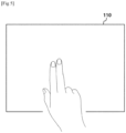
calculation circuit 310 may select a valid touch group including the two or more valid touch nodes. - When the user inputs a horizontal or vertical multi-touch on the
panel 110 as illustrated inFIG. 5 , the touch coordinatecalculation circuit 310 may select the valid touch group, of which the touch sensing value is greater than or equal to the first reference value (e.g., 10) from among the plurality of touch nodes, as illustrated inFIG. 6 . - In the valid touch group of
FIG. 6 , two touch areas corresponding to the multi-touch are adjacent to each other. In other words, an overlapping area is present between a first touch area and a second touch area. - In this case, the touch coordinate
calculation circuit 310 has to separate the two touch areas corresponding to the multi-touch from each other and may individually calculate touch coordinates for the first touch area and touch coordinates for the second touch area. - In an embodiment, in order to separate the two touch areas, the touch coordinate
calculation circuit 310 may classify the valid touch group into three or more line units in one direction, as illustrated inFIG. 8 . Here, the touch coordinatecalculation circuit 310 may classify the valid touch group into three or more lines when the number of valid touch nodes included in the valid touch group is greater than or equal to a preset reference number. - In other words, the number of valid touch nodes in the valid touch group corresponding to the multi-touch is greater than the number of valid touch nodes in the valid touch group corresponding to a single touch. For the single touch, the valid touch group need not be separated. Therefore, in an embodiment, a reference number may be set so as to determine whether the valid touch group is the multi-touch or the single touch. When the number of valid touch nodes in the valid touch group is greater than or equal to the reference number, the valid touch group is determined to be the multi-touch and is classified into three or more lines.
- When the number of valid touch nodes in the valid touch group is smaller than the reference number, the touch coordinate
calculation circuit 310 may calculate single touch coordinates for the valid touch group. - Meanwhile, before classifying the valid touch group into three or more line units in one direction, the touch coordinate
calculation circuit 310 may set a rectangular analysis area including the valid touch group as illustrated inFIG. 7 . Here, the touch coordinatecalculation circuit 310 may set the analysis area by using horizontal side start/end information (e.g., c2/c8 inFIG. 7 ) and vertical side start/end information (e.g., r4/r7 inFIG. 7 ) of the valid touch group. - The touch coordinate
calculation circuit 310 may compare the horizontal side length with the vertical side length of the analysis area and may determine a direction corresponding to the shorter side as one direction. - For example, since the vertical side length L2 is shorter than the horizontal side length L1 in the analysis area as illustrated in
FIG. 7 , the touch coordinatecalculation circuit 310 may determine the vertical direction of thepanel 110 as one direction. - The touch coordinate
calculation circuit 310, which has determined one direction, may classify the valid touch groups into three or more lines in one direction and may sum touch sensing values for each of the three or more lines. - For example, when the vertical direction of the panel is one direction, the touch coordinate
calculation circuit 310 may divide the valid touch group into seven lines (LINE1 to LINE7 inFIG. 8 ) corresponding to the vertical direction of thepanel 110, as illustrated inFIG. 8 . The touch coordinatecalculation circuit 310 may sum touch sensing values of (r5,c2) and (r6,c2), which are valid touch nodes included in a first line (LINE1 inFIG. 8 ), and may sum touch sensing values of (r4,c3), (r5,c3), (r6,c3), and (r7,c3), which are valid touch nodes included in a second line (LINE2 inFIG. 8 ). - The touch coordinate
calculation circuit 310 may calculate the sums of a third line (LINE3 inFIG. 8 ) to a seventh line (LINE7 inFIG. 8 ) in the same manner as described above and may calculate the sums (e.g., 47, 131, 96, 51, 98, 150, and 77) of the respective lines. - The touch coordinate
calculation circuit 310, which has calculated the sum of each line, may use the sum of each of the three or more lines to determine a separation line (e.g., the overlapping area inFIG. 6 ) for dividing the valid touch group into a first group (e.g., the first touch area inFIG. 6 ) and a second group (e.g., the second touch area inFIG. 6 ) from among the three or more lines. - Specifically, the touch coordinate
calculation circuit 310 may determine a first highest line with the highest sum on the first group side and a second highest line with the highest sum on the second group side from among the sums of the respective lines as illustrated inFIG. 9 . Here, since the multi-touch involves multiple touch nodes simultaneously sensing two touch inputs, high touch sensing values may be present on both sides (the first group side and the second group side) of the valid touch group. The highest lines with the highest sum may be respectively determined on both sides of the valid touch group. Here, the touch coordinatecalculation circuit 310 may prestore a highest line reference value for determining the highest line and may determine the highest line by comparing the prestored sums of the respective lines with the highest line reference value. - In
FIG. 8 , the first highest line may be the second line LINE2, and the second highest line may be the sixth line LINE6. The sum of the first highest line and the sum of the second highest line may correspond to a first crest and a second crest in a sum graph as illustrated inFIG. 9 . - Here, the separation line corresponding to the overlapping area of the multi-touch may be located between the first highest line and the second highest line, and the sum of the touch sensing values may be smaller than the sum of the first highest line and the sum of the second highest line.
- Accordingly, the touch coordinate
calculation circuit 310 may determine a separation line from among one or more lines located between the first highest line and the second highest line. - The touch coordinate
calculation circuit 310 may determine, as the separation line, a line of which the sum is smaller than the sum of the first highest line by a second reference value or more and smaller than the sum of the second highest line by the second reference value or more from among the one or more lines. - For example, in
FIG. 8 , one or more lines may be the third line LINE3 to the fifth line LINES, and when the second reference value is 70, the separation line may be determined to be the fourth line LINE4. - In an embodiment, when there are two or more lines of which the sum is smaller than the sum of the first highest line by the second reference value or more and smaller than the sum of the second highest line by the second reference value or more, the touch coordinate
calculation circuit 310 may determine, as the separation line, the line with the smallest sum from among the two or more lines. - The sum of the separation line described above may correspond to a valley in the sum graph as illustrated in
FIG. 9 . - In other words, the touch coordinate
calculation circuit 310 determines, as the separation line, the line corresponding to the valley from among the respective lines of the valid touch group. - The touch coordinate
calculation circuit 310, which has determined the separation line, may separate the valid touch group into the first group and the second group, based on the separation line. - The touch coordinate
calculation circuit 310 may calculate touch coordinates of the first group and touch coordinates of the second group. Here, the touch coordinatecalculation circuit 310 may change the touch sensing values of the valid touch nodes corresponding to the separation line to a touch sensing value smaller than the first reference value. In other words, the touch coordinatecalculation circuit 310 may change the valid touch nodes corresponding to the separation line to invalid touch nodes. - The configuration in which the touch coordinate
calculation circuit 310 separates the multi-touch input in the horizontal or vertical direction of thepanel 110 has been described above. - Hereinafter, a configuration in which the touch coordinate
calculation circuit 310 separates the multi-touch the user inputs on thepanel 110 in a diagonal direction, as illustrated inFIG. 10 , is described. - First, when the user inputs a diagonal multi-touch on the
panel 110 as illustrated inFIG. 10 , the touch coordinatecalculation circuit 310 may select a valid touch group, of which a touch sensing value is greater than or equal to a first reference value from among a plurality of touch nodes, as illustrated inFIG. 11 . - In
FIG. 11 , in the valid touch group, two touch areas corresponding to the multi-touch are adjacent to each other, and an overlapping area is present between a first touch area and a second touch area. Here, the overlapping area may be present in the same diagonal direction as an multi-touch input direction. - In this case, the touch coordinate
calculation circuit 310 has to determine, as the diagonal direction of thepanel 110, one direction for classifying three or more lines. - In order to determine the diagonal direction of the
panel 110 as one direction, the touch coordinatecalculation circuit 310 may set a rectangular analysis area including the valid touch group as illustrated inFIG. 12 and may determine one direction by using touch sensing values of touch nodes ((r3,c4), (r3,c7), (r8,c4), and (r8,c7) inFIG. 12 ) respectively located at four corners of the analysis area. - Specifically, the touch coordinate
calculation circuit 310 may calculate a first comparison value by summing a touch sensing value of a first touch node ((r3,c4) inFIG. 12 , indicated by a dashed rhombus) located at a first corner and a touch sensing value of a second touch node ((r8,c7) inFIG. 12 , indicated by a dashed rhombus) located at a second corner facing the first corner in a first diagonal direction. - The touch coordinate
calculation circuit 310 may calculate a second comparison value by summing a touch sensing value of a third touch node ((r3,c7) inFIG. 12 , indicated by a dashed circle) located at a third corner and a touch sensing value of a fourth touch node ((r8,c4) inFIG. 12 , indicated by a dashed circle) located at a fourth corner facing the second corner in a second diagonal direction. - The touch coordinate
calculation circuit 310 may compare the first comparison value with the second comparison value and may determine the diagonal direction with the smaller value as one direction. - In
FIG. 12 , since the first comparison value is 4 and the second comparison value is 50, the touch coordinatecalculation circuit 310 may determine the first diagonal direction, which is an upper left-lower right direction, as one direction. - In other words, the touch coordinate
calculation circuit 310 may determine, as one direction, a diagonal direction opposite to the diagonal direction in which the multi-touch is input. - For example, when the multi-touch is input in the second diagonal direction, which is an upper right-lower left direction, the valid touch nodes are present in the third corner and the fourth corner corresponding to the second diagonal direction, and the valid touch nodes are not present in the first corner and the second corner corresponding to the first diagonal direction. Therefore, the first comparison value may be smaller than the second comparison value. In this manner, the touch coordinate
calculation circuit 310 may determine the first diagonal direction, which is the diagonal direction opposite to the second diagonal direction, as one direction. - The touch coordinate
calculation circuit 310, which has determined one direction, may classify the valid touch groups into three or more lines in one direction and may sum touch sensing values for each of the three or more lines. - For example, when the first diagonal direction of the panel is one direction, the touch coordinate
calculation circuit 310 may divide the valid touch group into nine lines (LINE1 to LINE9 inFIG. 13 ) corresponding to the first diagonal direction of thepanel 110, as illustrated inFIG. 13 . The touch coordinatecalculation circuit 310 may sum touch a sensing value of (r3,c7), which is a valid touch node included in a first line (LINE1 inFIG. 13 ), and may sum touch sensing values of (r3,c6) and (r4,c7), which are valid touch nodes included in a second line (LINE2 inFIG. 13 ). - The touch coordinate
calculation circuit 310 may calculate the sums of a third line (LINE3 inFIG. 13 ) to a ninth line (LINE9 inFIG. 13 ) in the same manner as described above and may calculate the sums (e.g., 26, 86, 161, 106, 63, 104, 161, 85, and 24) of the respective lines. - The touch coordinate
calculation circuit 310, which has calculated the sum of each line, may use the sum of each of the three or more lines to determine a separation line (e.g., the overlapping area inFIG. 11 ) for dividing the valid touch group into a first group (e.g., the first touch area inFIG. 11 ) and a second group (e.g., the second touch area inFIG. 11 ) from among the three or more lines. Here, the sum of each line may form a graph as illustrated inFIG. 14 , and the touch coordinatecalculation circuit 310 may determine the third line (LINE3 inFIG. 13 ) as the first highest line and may determine the seventh line (LINE7 inFIG. 13 ) as the second highest line. - The touch coordinate
calculation circuit 310 may determine a separation line from among one or more lines located between the first highest line and the second highest line. - The touch coordinate
calculation circuit 310 may determine, as the separation line, a line of which the sum is smaller than the sum of the first highest line by a second reference value or more and smaller than the sum of the second highest line by the second reference value or more from among the one or more lines. - When there are two or more lines of which the sum is smaller than the sum of the first highest line by the second reference value or more and smaller than the sum of the second highest line by the second reference value or more, the touch coordinate
calculation circuit 310 may determine, as the separation line, the line with the smallest sum from among the two or more lines. - For example, the touch coordinate
calculation circuit 310 may determine the fifth line (LINES inFIG. 13 ), which is a line corresponding to a valley inFIG. 14 , as the separation line. - The touch coordinate
calculation circuit 310, which has determined the separation line, may separate the valid touch group into the first group and the second group, based on the separation line. - The touch coordinate
calculation circuit 310 may calculate touch coordinates of the first group and touch coordinates of the second group. - The touch coordinate tracking
circuit 320 assigns a touch ID to the touch coordinates calculated by the touch coordinatecalculation circuit 310. Here, the touch ID may be information for associating the touch coordinates calculated by the touch coordinatecalculation circuit 310. - In an embodiment, the touch coordinate tracking
circuit 320 may assign, to the touch coordinates of the first group and the touch coordinates of the second group, touch IDs corresponding to the multi-touch. - The touch coordinate tracking
circuit 320 may output the touch coordinates and the touch ID of the first group and the touch coordinates and the touch ID of the second group to the touch coordinatecorrection circuit 330. - The touch coordinate
correction circuit 330 may correct the touch coordinates output from the touch coordinate trackingcircuit 320 by using a smoothing technique. Here, the smoothing technique may refer to a technique for reducing noise in touch coordinates. - The touch coordinates corrected by the touch coordinate
correction circuit 330 and the touch ID assigned to the touch coordinates may be output to thehost 30. - In other words, the touch coordinates of the first group and the touch ID corresponding to the multi-touch, and the touch coordinates of the second group and the touch ID corresponding to the multi-touch may be output to the
host 30. - As described above, since the touch sensing apparatus including the touch coordinate
calculation circuit 310 classifies the valid touch groups into line units and sums the touch sensing values of the respective lines to determine the separation line, the multi-touch may be separated quickly and accurately. - A process by which the touch sensing apparatus separates a multi-touch and calculates touch coordinates is described below.
-
FIG. 15 is a flowchart showing a process of calculating touch coordinates for a multi-touch in a touch sensing apparatus according to an embodiment. Here, the touch sensing apparatus may be thetouch controller 160 or may be the T-IC including thetouch driver 150 and thetouch controller 160. - Referring to
FIG. 15 , the touch sensing apparatus may select a valid touch group including two or more valid touch nodes, of which the touch sensing values are greater than or equal to a first reference value from among a plurality of touch nodes, based on raw data (S1510). Here, the first reference value may be a reference value for determining whether the touch sensing value of the touch node is valid or invalid. - The touch sensing apparatus may set a rectangular analysis area including the valid touch group from among the plurality of touch nodes and classify the analysis area into three or more lines in one direction (S1520, S1530).
- The touch sensing apparatus may sum the touch sensing values for each of the three or more lines and then use the sum of each of the three or more lines to determine a separation line for separating the valid touch group into a first group and a second group from among the three or more lines (S1540, S1550).
- The touch sensing apparatus may separate the valid touch group into the first group and the second group, based on the separation line, and may calculate touch coordinates of the first group and touch coordinates of the second group (S1560, S1570).
- The process described above may be more specific depending on the direction of the multi-touch input by the user.
-
FIG. 16 is a flowchart showing a process of calculating touch coordinates for a horizontal or vertical multi-touch in a touch sensing apparatus according to an embodiment. - Referring to
FIG. 16 , the touch sensing apparatus may select a valid touch group including two or more valid touch nodes, of which the touch sensing values are greater than or equal to a first reference value from among a plurality of touch nodes, based on raw data (S1610). - The touch sensing apparatus may set a rectangular analysis area including the valid touch group from among the plurality of touch nodes (S1620).
- The touch sensing apparatus may compare the horizontal side length of the analysis area with the vertical side length of the analysis area and may determine the direction corresponding to the shorter side as one direction (S1630, S1640).
- The touch sensing apparatus may classify the touch sensing values of the valid touch group included in the analysis area into three or more line units in one direction (S1650).
- After summing the touch sensing values for each of the three or more lines, the touch sensing apparatus may determine the first highest line with the highest sum on the first group side and the second highest line with the highest sum on the second group side from among the three or more lines (S1660, S1670).
- The touch sensing apparatus may determine the separation line by using the first highest line and the second highest line (S1680). In operation S1680, the touch sensing apparatus may determine, as the separation line, a line of which the sum is smaller than the sum of the first highest line by the second reference value or more and smaller than the sum of the second highest line by the second reference value or more from among one or more lines located between the first highest line and the second highest line.
- The touch sensing apparatus may separate the valid touch group into the first group and the second group, based on the separation line, and may calculate touch coordinates of the first group and touch coordinates of the second group (S 1690).
- After
operation S 1690, the touch sensing apparatus may assign, to the touch coordinates of the first group and the touch coordinates of the second group, touch IDs corresponding to the multi-touch. - The touch sensing apparatus may output, to the
host 30, the touch coordinates of the first group, the touch coordinates of the second group, and the touch IDs corresponding to the multi-touch. -
FIG. 17 is a flowchart showing a process of calculating touch coordinates for a diagonal multi-touch in a touch sensing apparatus according to an embodiment. - Referring to
FIG. 17 , the touch sensing apparatus may select a valid touch group including two or more valid touch nodes, of which the touch sensing values are greater than or equal to a first reference value from among a plurality of touch nodes, based on raw data (S1710). - The touch sensing apparatus may set a rectangular analysis area including the valid touch group from among the plurality of touch nodes (S1720).
- The touch sensing apparatus identify touch nodes located at corners of the analysis area and may determine one direction by using the touch sensing values of the respective touch nodes located at the corners (S1730, S1740). In operation S1740, the touch sensing apparatus may calculate a first comparison value by summing a touch sensing value of a first touch node located at a first corner of the analysis area and a touch sensing value of a second touch node located at a second corner of the analysis area facing the first corner in a first diagonal direction. The touch sensing apparatus may calculate a second comparison value by summing a touch sensing value of a third touch node located at a third corner of the analysis area and a touch sensing value of a fourth touch node located at a fourth corner of the analysis area facing the third corner in a second diagonal direction. Thereafter, the touch sensing apparatus may compare the first comparison value with the second comparison value and may determine the diagonal direction with the smaller value as one direction.
- After
operation S 1740, the touch sensing apparatus may classify the touch sensing values of the valid touch group included in the analysis area into three or more line units in one direction (S1750). - After summing the touch sensing values for each of the three or more lines, the touch sensing apparatus may determine the first highest line with the highest sum on the first group side and the second highest line with the highest sum on the second group side from among the three or more lines (S1760, S1770).
- The touch sensing apparatus may determine the separation line by using the first highest line and the second highest line (S1780). In operation S1780, the touch sensing apparatus may determine, as the separation line, a line of which the sum is smaller than the sum of the first highest line by the second reference value or more and smaller than the sum of the second highest line by the second reference value or more from among one or more lines located between the first highest line and the second highest line.
- The touch sensing apparatus may separate the valid touch group into the first group and the second group, based on the separation line, and may calculate touch coordinates of the first group and touch coordinates of the second group (S 1790).
- After operation S1790, the touch sensing apparatus may assign, to the touch coordinates of the first group and the touch coordinates of the second group, touch IDs corresponding to the multi-touch.
- The touch sensing apparatus may output, to the
host 30, the touch coordinates of the first group, the touch coordinates of the second group, and the touch IDs corresponding to the multi-touch. - In an embodiment, when the touch sensing apparatus fails to determine the separation line through operations S1630 to S1680 of
FIG. 16 , the touch sensing apparatus may determine the separation line through operations S1740 to S 1780 ofFIG. 17 . - In contrast, when the touch sensing apparatus fails to determine the separation line through operations S1740 to S 1780 of
FIG. 17 , the touch sensing apparatus may determine the separation line through operations S1630 toS 1680 ofFIG. 16 .
Claims (15)
- A touch sensing apparatus comprising a touch coordinate calculation circuit that:selects a valid touch group including two or more valid touch nodes, of which a touch sensing value is greater than or equal to a first reference value from among a plurality of touch nodes,classifies the valid touch group into three or more line units in one direction,sums touch sensing values for each of the three or more lines,determines a separation line for separating the valid touch group into a first group and a second group from among the three or more lines by using a sum of each of the three or more lines,separates the valid touch group into the first group and the second group based on the separation line, andcalculates touch coordinates of the first group and touch coordinates of the second group.
- The touch sensing apparatus of claim 1, wherein the touch coordinate calculation circuit classifies the valid touch group into the three or more lines when a number of valid touch nodes included in the valid touch group is greater than or equal to a preset reference number.
- The touch sensing apparatus of claim 1, wherein the touch coordinate calculation circuit:sets a rectangular analysis area including the valid touch group,compares a horizontal side length with a vertical side length of the analysis area, anddetermines a direction corresponding to a side with a shorter length as the one direction.
- The touch sensing apparatus claim 1, wherein the touch coordinate calculation circuit:determines a first highest line with a highest sum on a first group side and a second highest line with a highest sum on a second group side from among the three or more lines, anddetermines the separation line from among one or more lines located between the first highest line and the second highest line.
- The touch sensing apparatus of claim 4, wherein the touch coordinate calculation circuit determines, as the separation line, a line of which a sum is smaller than a sum of the first highest line by a second reference value or more and smaller than a sum of the second highest line by the second reference value or more from among the one or more lines.
- The touch sensing apparatus of claim 5, wherein, when there are two or more lines of which sum is smaller than the sum of the first highest line by the second reference value or more and smaller than the sum of the second highest line by the second reference value or more, the touch coordinate calculation circuit determines, as the separation line, a line with a smallest sum from among the two or more lines.
- The touch sensing apparatus of claim 1, wherein the touch coordinate calculation circuit:sets a rectangular analysis area including the valid touch group anddetermines the one direction by using touch sensing values of touch nodes respectively located at four corners of the analysis area.
- The touch sensing apparatus of claim 7, wherein the touch coordinate calculation circuit:calculates a first comparison value by summing a touch sensing value of a first touch node located at a first corner and a touch sensing value of a second touch node located at a second corner facing the first corner in a first diagonal direction,calculates a second comparison value by summing a touch sensing value of a third touch node located at a third corner and a touch sensing value of a fourth touch node located at a fourth corner facing the third corner in a second diagonal direction,compares the first comparative value with the second comparison value, anddetermines a diagonal direction with a smaller value as the one direction.
- The touch sensing apparatus claim 1, further comprising a touch coordinate tracking circuit that assigns, to the touch coordinates of the first group and the touch coordinates of the second group, touch identities (IDs) corresponding to a multi-touch.
- The touch sensing apparatus claim 1, wherein one line includes one or more valid touch nodes included in the valid touch group, and the touch coordinate calculation circuit calculates a sum of the one line by summing touch sensing values of each of the one or more valid touch nodes included in the one line.
- A touch sensing method of a touch sensing apparatus, the touch sensing method comprising:selecting a valid touch group including two or more valid touch nodes, of which a touch sensing value is greater than or equal to a first reference value from among a plurality of touch nodes;setting a rectangular analysis area including the valid touch group from among the plurality of touch nodes;classifying the analysis area into three or more line units in one direction;summing touch sensing values for each of the three or more lines;determining a separation line for separating the valid touch group into a first group and a second group from among the three or more lines by using a sum of each of the three or more lines;separating the valid touch group into the first group and the second group, based on the separation line; andcalculating touch coordinates of the first group and touch coordinates of the second group.
- The touch sensing method of claim 11, wherein the classifying comprises:comparing a horizontal side length of the analysis area with a vertical side length of the analysis area and determining, as the one direction, a direction corresponding to a side with a shorter length; andclassifying touch sensing values of the valid touch group included in the analysis area into three or more line units in the one direction.
- The touch sensing method of claim 11, wherein the classifying comprises:calculating a first comparison value by summing a touch sensing value of a first touch node located at a first corner of the analysis area and a touch sensing value of a second touch node located at a second corner of the analysis area facing the first corner in a first diagonal direction;calculating a second comparison value by summing a touch sensing value of a third touch node located at a third corner of the analysis area and a touch sensing value of a fourth touch node located at a fourth corner of the analysis area facing the third corner in a second diagonal direction;comparing the first comparison value with the second comparison value and determining a diagonal direction with a smaller value as the one direction; andclassifying touch sensing values of the valid touch group included in the analysis area into three or more line units in the one direction.
- The touch sensing method claims 11, wherein the determining comprises:determining a first highest line with a highest sum on a first group side and a second highest line with a highest sum on a second group side from among the three or more lines; anddetermining, as the separation line, a line of which a sum is smaller than a sum of the first highest line by a second reference value or more and smaller than a sum of the second highest line by the second reference value or more from among one or more lines located between the first highest line and the second highest line.
- The touch sensing method claim 11, further comprising:assigning, to the touch coordinates of the first group and the touch coordinates of the second group, touch identities (IDs) corresponding to a multi-touch; andoutputting, to a host, the touch coordinates of the first group, the touch coordinates of the second group, and the touch IDs.
Applications Claiming Priority (2)
| Application Number | Priority Date | Filing Date | Title |
|---|---|---|---|
| KR1020210187176A KR20230097555A (en) | 2021-12-24 | 2021-12-24 | Touch sensing device and touch sensing method |
| PCT/KR2022/019230 WO2023121034A1 (en) | 2021-12-24 | 2022-11-30 | Touch sensing apparatus and touch sensing method |
Publications (2)
| Publication Number | Publication Date |
|---|---|
| EP4455847A1 true EP4455847A1 (en) | 2024-10-30 |
| EP4455847A4 EP4455847A4 (en) | 2025-12-17 |
Family
ID=86902981
Family Applications (1)
| Application Number | Title | Priority Date | Filing Date |
|---|---|---|---|
| EP22911667.8A Pending EP4455847A4 (en) | 2021-12-24 | 2022-11-30 | TOUCH DETECTION DEVICE AND TOUCH DETECTION METHOD |
Country Status (5)
| Country | Link |
|---|---|
| US (1) | US12632143B2 (en) |
| EP (1) | EP4455847A4 (en) |
| KR (1) | KR20230097555A (en) |
| CN (1) | CN118401918A (en) |
| WO (1) | WO2023121034A1 (en) |
Family Cites Families (11)
| Publication number | Priority date | Publication date | Assignee | Title |
|---|---|---|---|---|
| JP5451181B2 (en) * | 2009-05-25 | 2014-03-26 | 株式会社ジャパンディスプレイ | Sensor device for detecting contact or proximity of an object |
| WO2011161673A2 (en) | 2010-06-21 | 2011-12-29 | N-Trig Ltd. | System and method for finger resolution in touch screens |
| KR20120089101A (en) * | 2011-02-01 | 2012-08-09 | 삼성전자주식회사 | Methods of detecting multi-touches on a touch panel and methods of operating a touch screen device using the same |
| US8913019B2 (en) | 2011-07-14 | 2014-12-16 | Microsoft Corporation | Multi-finger detection and component resolution |
| KR101493557B1 (en) * | 2011-12-09 | 2015-02-16 | 엘지디스플레이 주식회사 | Display having touch sensor and touch data processing method thereof |
| KR101885216B1 (en) * | 2011-12-30 | 2018-08-30 | 삼성전자주식회사 | Multi touch segmentation method in a touch sensing system |
| KR101964845B1 (en) * | 2013-01-30 | 2019-04-04 | 삼성디스플레이 주식회사 | Touch screen display device |
| KR102259238B1 (en) * | 2014-09-12 | 2021-06-01 | 엘지디스플레이 주식회사 | Driving Apparatus Of Touch Panel |
| KR102558004B1 (en) | 2016-05-17 | 2023-07-20 | 삼성전자주식회사 | Touch screen apparatus capable of touch sensing and fingerprint sensing and method of driving the touch screen apparatus, and electronic apparatus including the same |
| KR20190007148A (en) * | 2017-07-12 | 2019-01-22 | 주식회사 지2터치 | Touch screen for separating multi touch points |
| KR20190009033A (en) * | 2017-07-18 | 2019-01-28 | 주식회사 지2터치 | Touch screen for separating multi touch points |
-
2021
- 2021-12-24 KR KR1020210187176A patent/KR20230097555A/en active Pending
-
2022
- 2022-11-30 US US18/723,195 patent/US12632143B2/en active Active
- 2022-11-30 EP EP22911667.8A patent/EP4455847A4/en active Pending
- 2022-11-30 WO PCT/KR2022/019230 patent/WO2023121034A1/en not_active Ceased
- 2022-11-30 CN CN202280083095.0A patent/CN118401918A/en active Pending
Also Published As
| Publication number | Publication date |
|---|---|
| US20250068279A1 (en) | 2025-02-27 |
| EP4455847A4 (en) | 2025-12-17 |
| KR20230097555A (en) | 2023-07-03 |
| US12632143B2 (en) | 2026-05-19 |
| CN118401918A (en) | 2024-07-26 |
| WO2023121034A1 (en) | 2023-06-29 |
Similar Documents
| Publication | Publication Date | Title |
|---|---|---|
| KR102804945B1 (en) | Touch sensing device for avoiding noise and display device including the same | |
| US10452180B2 (en) | Driving circuit and sensing unit thereof | |
| CN109471551B (en) | Touch display device, gate driving circuit and driving method thereof | |
| KR102378398B1 (en) | Display with touch screen and driving circuit | |
| CN107305445B (en) | Touch noise filtering method and touch device | |
| CN110383219B (en) | Touch controller, touch display system and touch display synchronization method | |
| CN111381718B (en) | Touch sensing device, touch sensing system and touch panel driving method | |
| CN113031789B (en) | Touch sensing device | |
| US11294508B2 (en) | Integrated circuit for driving panel and display device including the same | |
| KR20140076054A (en) | Display device having touch sensors and control method of gate driving circuit thereof | |
| US20150277607A1 (en) | Input device and display device | |
| KR20180132499A (en) | Device and method for driving touch screen including fingerprint sensing array, and driving integrated circuit for driving touch screen including fingerprint sensing array | |
| KR20190029028A (en) | Touch Device And Method Of Driving The Same | |
| CN103164095B (en) | There is display device and the touch data disposal route thereof of touch sensor | |
| US9811190B2 (en) | Display driving method and apparatus for in-cell touch display screen, and display apparatus | |
| US12632143B2 (en) | Touch sensing apparatus for separation of a multi-touch and touch sensing method therefor | |
| CN113010032B (en) | Touch sensing device | |
| US12001632B2 (en) | Touch sensing device and touch sensing method | |
| KR20130078068A (en) | A method for setting sensing period and the touch screen panel driving system using the method | |
| KR20190009033A (en) | Touch screen for separating multi touch points | |
| US11256351B2 (en) | Display system | |
| CN116360618A (en) | touch sensing device | |
| US20220129135A1 (en) | Touch device and driving method thereof | |
| KR101688428B1 (en) | Display driver ic, display device with integrated touch screen and method for driving the same | |
| US11334188B2 (en) | Touch driving device, relay device and method for implementing touch of multi-vision |
Legal Events
| Date | Code | Title | Description |
|---|---|---|---|
| STAA | Information on the status of an ep patent application or granted ep patent |
Free format text: STATUS: THE INTERNATIONAL PUBLICATION HAS BEEN MADE |
|
| PUAI | Public reference made under article 153(3) epc to a published international application that has entered the european phase |
Free format text: ORIGINAL CODE: 0009012 |
|
| STAA | Information on the status of an ep patent application or granted ep patent |
Free format text: STATUS: REQUEST FOR EXAMINATION WAS MADE |
|
| 17P | Request for examination filed |
Effective date: 20240709 |
|
| AK | Designated contracting states |
Kind code of ref document: A1 Designated state(s): AL AT BE BG CH CY CZ DE DK EE ES FI FR GB GR HR HU IE IS IT LI LT LU LV MC ME MK MT NL NO PL PT RO RS SE SI SK SM TR |
|
| DAV | Request for validation of the european patent (deleted) | ||
| DAX | Request for extension of the european patent (deleted) | ||
| A4 | Supplementary search report drawn up and despatched |
Effective date: 20251113 |
|
| RIC1 | Information provided on ipc code assigned before grant |
Ipc: G06F 3/041 20060101AFI20251107BHEP Ipc: G06F 3/044 20060101ALI20251107BHEP |