EP4455827A1 - Operation amount detection device - Google Patents
Operation amount detection device Download PDFInfo
- Publication number
- EP4455827A1 EP4455827A1 EP22910451.8A EP22910451A EP4455827A1 EP 4455827 A1 EP4455827 A1 EP 4455827A1 EP 22910451 A EP22910451 A EP 22910451A EP 4455827 A1 EP4455827 A1 EP 4455827A1
- Authority
- EP
- European Patent Office
- Prior art keywords
- center axis
- axial direction
- elastic body
- rotation center
- wall portions
- Prior art date
- Legal status (The legal status is an assumption and is not a legal conclusion. Google has not performed a legal analysis and makes no representation as to the accuracy of the status listed.)
- Granted
Links
Images





Classifications
-
- G—PHYSICS
- G05—CONTROLLING; REGULATING
- G05G—CONTROL DEVICES OR SYSTEMS INSOFAR AS CHARACTERISED BY MECHANICAL FEATURES ONLY
- G05G1/00—Controlling members, e.g. knobs or handles; Assemblies or arrangements thereof; Indicating position of controlling members
- G05G1/30—Controlling members actuated by foot
- G05G1/38—Controlling members actuated by foot comprising means to continuously detect pedal position
-
- B—PERFORMING OPERATIONS; TRANSPORTING
- B60—VEHICLES IN GENERAL
- B60T—VEHICLE BRAKE CONTROL SYSTEMS OR PARTS THEREOF; BRAKE CONTROL SYSTEMS OR PARTS THEREOF, IN GENERAL; ARRANGEMENT OF BRAKING ELEMENTS ON VEHICLES IN GENERAL; PORTABLE DEVICES FOR PREVENTING UNWANTED MOVEMENT OF VEHICLES; VEHICLE MODIFICATIONS TO FACILITATE COOLING OF BRAKES
- B60T11/00—Transmitting braking action from initiating means to ultimate brake actuator without power assistance or drive or where such assistance or drive is irrelevant
- B60T11/10—Transmitting braking action from initiating means to ultimate brake actuator without power assistance or drive or where such assistance or drive is irrelevant transmitting by fluid means, e.g. hydraulic
- B60T11/16—Master control, e.g. master cylinders
- B60T11/18—Connection thereof to initiating means
-
- B—PERFORMING OPERATIONS; TRANSPORTING
- B60—VEHICLES IN GENERAL
- B60T—VEHICLE BRAKE CONTROL SYSTEMS OR PARTS THEREOF; BRAKE CONTROL SYSTEMS OR PARTS THEREOF, IN GENERAL; ARRANGEMENT OF BRAKING ELEMENTS ON VEHICLES IN GENERAL; PORTABLE DEVICES FOR PREVENTING UNWANTED MOVEMENT OF VEHICLES; VEHICLE MODIFICATIONS TO FACILITATE COOLING OF BRAKES
- B60T7/00—Brake-action initiating means
- B60T7/02—Brake-action initiating means for personal initiation
- B60T7/04—Brake-action initiating means for personal initiation foot actuated
- B60T7/042—Brake-action initiating means for personal initiation foot actuated by electrical means, e.g. using travel or force sensors
-
- B—PERFORMING OPERATIONS; TRANSPORTING
- B60—VEHICLES IN GENERAL
- B60T—VEHICLE BRAKE CONTROL SYSTEMS OR PARTS THEREOF; BRAKE CONTROL SYSTEMS OR PARTS THEREOF, IN GENERAL; ARRANGEMENT OF BRAKING ELEMENTS ON VEHICLES IN GENERAL; PORTABLE DEVICES FOR PREVENTING UNWANTED MOVEMENT OF VEHICLES; VEHICLE MODIFICATIONS TO FACILITATE COOLING OF BRAKES
- B60T7/00—Brake-action initiating means
- B60T7/02—Brake-action initiating means for personal initiation
- B60T7/04—Brake-action initiating means for personal initiation foot actuated
- B60T7/06—Disposition of pedal
-
- B—PERFORMING OPERATIONS; TRANSPORTING
- B60—VEHICLES IN GENERAL
- B60T—VEHICLE BRAKE CONTROL SYSTEMS OR PARTS THEREOF; BRAKE CONTROL SYSTEMS OR PARTS THEREOF, IN GENERAL; ARRANGEMENT OF BRAKING ELEMENTS ON VEHICLES IN GENERAL; PORTABLE DEVICES FOR PREVENTING UNWANTED MOVEMENT OF VEHICLES; VEHICLE MODIFICATIONS TO FACILITATE COOLING OF BRAKES
- B60T8/00—Arrangements for adjusting wheel-braking force to meet varying vehicular or ground-surface conditions, e.g. limiting or varying distribution of braking force
- B60T8/17—Using electrical or electronic regulation means to control braking
-
- B—PERFORMING OPERATIONS; TRANSPORTING
- B60—VEHICLES IN GENERAL
- B60T—VEHICLE BRAKE CONTROL SYSTEMS OR PARTS THEREOF; BRAKE CONTROL SYSTEMS OR PARTS THEREOF, IN GENERAL; ARRANGEMENT OF BRAKING ELEMENTS ON VEHICLES IN GENERAL; PORTABLE DEVICES FOR PREVENTING UNWANTED MOVEMENT OF VEHICLES; VEHICLE MODIFICATIONS TO FACILITATE COOLING OF BRAKES
- B60T8/00—Arrangements for adjusting wheel-braking force to meet varying vehicular or ground-surface conditions, e.g. limiting or varying distribution of braking force
- B60T8/32—Arrangements for adjusting wheel-braking force to meet varying vehicular or ground-surface conditions, e.g. limiting or varying distribution of braking force responsive to a speed condition, e.g. acceleration or deceleration
- B60T8/321—Arrangements for adjusting wheel-braking force to meet varying vehicular or ground-surface conditions, e.g. limiting or varying distribution of braking force responsive to a speed condition, e.g. acceleration or deceleration deceleration
- B60T8/3255—Systems in which the braking action is dependent on brake pedal data
-
- B—PERFORMING OPERATIONS; TRANSPORTING
- B60—VEHICLES IN GENERAL
- B60T—VEHICLE BRAKE CONTROL SYSTEMS OR PARTS THEREOF; BRAKE CONTROL SYSTEMS OR PARTS THEREOF, IN GENERAL; ARRANGEMENT OF BRAKING ELEMENTS ON VEHICLES IN GENERAL; PORTABLE DEVICES FOR PREVENTING UNWANTED MOVEMENT OF VEHICLES; VEHICLE MODIFICATIONS TO FACILITATE COOLING OF BRAKES
- B60T8/00—Arrangements for adjusting wheel-braking force to meet varying vehicular or ground-surface conditions, e.g. limiting or varying distribution of braking force
- B60T8/32—Arrangements for adjusting wheel-braking force to meet varying vehicular or ground-surface conditions, e.g. limiting or varying distribution of braking force responsive to a speed condition, e.g. acceleration or deceleration
- B60T8/34—Arrangements for adjusting wheel-braking force to meet varying vehicular or ground-surface conditions, e.g. limiting or varying distribution of braking force responsive to a speed condition, e.g. acceleration or deceleration having a fluid pressure regulator responsive to a speed condition
- B60T8/40—Arrangements for adjusting wheel-braking force to meet varying vehicular or ground-surface conditions, e.g. limiting or varying distribution of braking force responsive to a speed condition, e.g. acceleration or deceleration having a fluid pressure regulator responsive to a speed condition comprising an additional fluid circuit including fluid pressurising means for modifying the pressure of the braking fluid, e.g. including wheel driven pumps for detecting a speed condition, or pumps which are controlled by means independent of the braking system
- B60T8/4072—Systems in which a driver input signal is used as a control signal for the additional fluid circuit which is normally used for braking
- B60T8/4081—Systems with stroke simulating devices for driver input
- B60T8/4086—Systems with stroke simulating devices for driver input the stroke simulating device being connected to, or integrated in the driver input device
-
- B—PERFORMING OPERATIONS; TRANSPORTING
- B60—VEHICLES IN GENERAL
- B60T—VEHICLE BRAKE CONTROL SYSTEMS OR PARTS THEREOF; BRAKE CONTROL SYSTEMS OR PARTS THEREOF, IN GENERAL; ARRANGEMENT OF BRAKING ELEMENTS ON VEHICLES IN GENERAL; PORTABLE DEVICES FOR PREVENTING UNWANTED MOVEMENT OF VEHICLES; VEHICLE MODIFICATIONS TO FACILITATE COOLING OF BRAKES
- B60T8/00—Arrangements for adjusting wheel-braking force to meet varying vehicular or ground-surface conditions, e.g. limiting or varying distribution of braking force
- B60T8/32—Arrangements for adjusting wheel-braking force to meet varying vehicular or ground-surface conditions, e.g. limiting or varying distribution of braking force responsive to a speed condition, e.g. acceleration or deceleration
- B60T8/34—Arrangements for adjusting wheel-braking force to meet varying vehicular or ground-surface conditions, e.g. limiting or varying distribution of braking force responsive to a speed condition, e.g. acceleration or deceleration having a fluid pressure regulator responsive to a speed condition
- B60T8/40—Arrangements for adjusting wheel-braking force to meet varying vehicular or ground-surface conditions, e.g. limiting or varying distribution of braking force responsive to a speed condition, e.g. acceleration or deceleration having a fluid pressure regulator responsive to a speed condition comprising an additional fluid circuit including fluid pressurising means for modifying the pressure of the braking fluid, e.g. including wheel driven pumps for detecting a speed condition, or pumps which are controlled by means independent of the braking system
- B60T8/4072—Systems in which a driver input signal is used as a control signal for the additional fluid circuit which is normally used for braking
- B60T8/4081—Systems with stroke simulating devices for driver input
- B60T8/409—Systems with stroke simulating devices for driver input characterised by details of the stroke simulating device
-
- G—PHYSICS
- G01—MEASURING; TESTING
- G01L—MEASURING FORCE, STRESS, TORQUE, WORK, MECHANICAL POWER, MECHANICAL EFFICIENCY, OR FLUID PRESSURE
- G01L5/00—Apparatus for, or methods of, measuring force, work, mechanical power, or torque, specially adapted for specific purposes
- G01L5/22—Apparatus for, or methods of, measuring force, work, mechanical power, or torque, specially adapted for specific purposes for measuring the force applied to control members, e.g. control members of vehicles, triggers
- G01L5/225—Apparatus for, or methods of, measuring force, work, mechanical power, or torque, specially adapted for specific purposes for measuring the force applied to control members, e.g. control members of vehicles, triggers to foot actuated controls, e.g. brake pedals
-
- G—PHYSICS
- G05—CONTROLLING; REGULATING
- G05G—CONTROL DEVICES OR SYSTEMS INSOFAR AS CHARACTERISED BY MECHANICAL FEATURES ONLY
- G05G1/00—Controlling members, e.g. knobs or handles; Assemblies or arrangements thereof; Indicating position of controlling members
- G05G1/30—Controlling members actuated by foot
-
- G—PHYSICS
- G05—CONTROLLING; REGULATING
- G05G—CONTROL DEVICES OR SYSTEMS INSOFAR AS CHARACTERISED BY MECHANICAL FEATURES ONLY
- G05G1/00—Controlling members, e.g. knobs or handles; Assemblies or arrangements thereof; Indicating position of controlling members
- G05G1/30—Controlling members actuated by foot
- G05G1/44—Controlling members actuated by foot pivoting
-
- G—PHYSICS
- G05—CONTROLLING; REGULATING
- G05G—CONTROL DEVICES OR SYSTEMS INSOFAR AS CHARACTERISED BY MECHANICAL FEATURES ONLY
- G05G1/00—Controlling members, e.g. knobs or handles; Assemblies or arrangements thereof; Indicating position of controlling members
- G05G1/30—Controlling members actuated by foot
- G05G1/46—Means, e.g. links, for connecting the pedal to the controlled unit
-
- G—PHYSICS
- G05—CONTROLLING; REGULATING
- G05G—CONTROL DEVICES OR SYSTEMS INSOFAR AS CHARACTERISED BY MECHANICAL FEATURES ONLY
- G05G5/00—Means for preventing, limiting or returning the movements of parts of a control mechanism, e.g. locking controlling member
- G05G5/03—Means for enhancing the operator's awareness of arrival of the controlling member at a command or datum position; Providing feel, e.g. means for creating a counterforce
-
- G—PHYSICS
- G05—CONTROLLING; REGULATING
- G05G—CONTROL DEVICES OR SYSTEMS INSOFAR AS CHARACTERISED BY MECHANICAL FEATURES ONLY
- G05G5/00—Means for preventing, limiting or returning the movements of parts of a control mechanism, e.g. locking controlling member
- G05G5/05—Means for returning or tending to return controlling members to an inoperative or neutral position, e.g. by providing return springs or resilient end-stops
-
- B—PERFORMING OPERATIONS; TRANSPORTING
- B60—VEHICLES IN GENERAL
- B60T—VEHICLE BRAKE CONTROL SYSTEMS OR PARTS THEREOF; BRAKE CONTROL SYSTEMS OR PARTS THEREOF, IN GENERAL; ARRANGEMENT OF BRAKING ELEMENTS ON VEHICLES IN GENERAL; PORTABLE DEVICES FOR PREVENTING UNWANTED MOVEMENT OF VEHICLES; VEHICLE MODIFICATIONS TO FACILITATE COOLING OF BRAKES
- B60T2220/00—Monitoring, detecting driver behaviour; Signalling thereof; Counteracting thereof
- B60T2220/04—Pedal travel sensor, stroke sensor; Sensing brake request
-
- B—PERFORMING OPERATIONS; TRANSPORTING
- B60—VEHICLES IN GENERAL
- B60T—VEHICLE BRAKE CONTROL SYSTEMS OR PARTS THEREOF; BRAKE CONTROL SYSTEMS OR PARTS THEREOF, IN GENERAL; ARRANGEMENT OF BRAKING ELEMENTS ON VEHICLES IN GENERAL; PORTABLE DEVICES FOR PREVENTING UNWANTED MOVEMENT OF VEHICLES; VEHICLE MODIFICATIONS TO FACILITATE COOLING OF BRAKES
- B60T2270/00—Further aspects of brake control systems not otherwise provided for
- B60T2270/82—Brake-by-Wire, EHB
-
- F—MECHANICAL ENGINEERING; LIGHTING; HEATING; WEAPONS; BLASTING
- F16—ENGINEERING ELEMENTS AND UNITS; GENERAL MEASURES FOR PRODUCING AND MAINTAINING EFFECTIVE FUNCTIONING OF MACHINES OR INSTALLATIONS; THERMAL INSULATION IN GENERAL
- F16D—COUPLINGS FOR TRANSMITTING ROTATION; CLUTCHES; BRAKES
- F16D66/00—Arrangements for monitoring working conditions, e.g. wear, temperature
- F16D2066/005—Force, torque, stress or strain
-
- G—PHYSICS
- G05—CONTROLLING; REGULATING
- G05G—CONTROL DEVICES OR SYSTEMS INSOFAR AS CHARACTERISED BY MECHANICAL FEATURES ONLY
- G05G2505/00—Means for preventing, limiting or returning the movements of parts of a control mechanism, e.g. locking controlling member
Definitions
- This disclosure relates to an operation amount detection device.
- an operation amount detection device that detects an operation amount of a pedal of a pedal device
- a device in which a strain body serving as a detection element is provided on a reaction force member that is connected to the pedal device and that transmits a reaction force against an operation force of the pedal to the pedal device, and a strain amount of the strain body is detected.
- An object of this disclosure is to provide an operation amount detection device in which an arrangement of a detection element is less likely to be restricted by a reaction force member.
- An operation amount detection device includes: a first member configured to rotate about a rotation center axis by an operation force input to a pedal and transmit a rotation torque; a second member configured to receive, from a reaction force member, a reaction force of the rotation torque transmitted from the first member, the second member being rotatable about the rotation center axis and movable relative to the first member in an axial direction of the rotation center axis, and being interposed between the first member and the reaction force member; a conversion mechanism configured to convert rotation of the first member into a relative movement of the first member and the second member in the axial direction to convert the rotation torque into a thrust force which is a force in the axial direction; an elastic body provided apart from the reaction force member and configured to be elastically deformed by the thrust force; and a detection element fixed to the elastic body and configured to detect a deformation amount of the elastic body.
- the elastic body and the detection element are positioned between the first member and the second member in the axial direction and rotate about the rotation center axis integrally with the first member or the second member.
- the operation amount detection device includes, for example, a support member including two wall portions that are apart from each other in the axial direction and that support the first member and the second member such that the first member and the second member are rotatable about the rotation center axis.
- the first member and the second member are positioned between the two wall portions, and relatively move in directions apart from each other in the axial direction by the operation force, and the first member is pressed against one of the wall portions.
- the elastic body and the detection element are positioned between the two wall portions and fixed to the other one of the wall portions.
- the operation amount detection device includes a support member including two wall portions that are apart from each other in the axial direction and that support the first member and the second member such that the first member and the second member are rotatable about the rotation center axis.
- the first member and the second member relatively move in directions approaching each other in the axial direction by the operation force and sandwich one of the wall portions.
- the elastic body and the detection element are positioned outside the two wall portions and fixed to the one of the wall portions.
- the wiring routing and the assembling workability of the detection element are improved.
- the first member constitutes a link of a parallel link.
- the following plurality of embodiments include the same components.
- the same components are denoted by the same reference signs, and redundant description thereof is omitted.
- the drawings are schematic, and dimensional relationships of elements, ratios of elements, and the like may be different from actual ones.
- the drawings also include portions having different dimensional relationships and ratios from each other.
- an initial number is used only for distinguishing parts, members, portions, positions, directions, and the like, and does not indicate an order or priority.
- Fig. 1 is a side view showing a pedal device 1 according to a first embodiment.
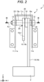
- Fig. 2 is a front view showing the pedal device 1 according to the first embodiment.
- the pedal device 1 shown in Figs. 1 and 2 is a brake pedal device mounted on a vehicle. It should be noted that the pedal device 1 may be an accelerator pedal device.
- An X direction corresponds to a front in a front-rear direction of the vehicle.
- AY direction corresponds to one side in a width direction of the vehicle.
- a Z direction corresponds to an upward direction in a vertical direction of the vehicle.
- the pedal device 1 includes a pedal 2 and an operation amount detection device 3.
- the pedal 2 has, for example, a plate shape, and is subjected to a depression operation by an operator.
- the operation amount detection device 3 detects and outputs an operation amount of the pedal 2.
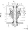
- Fig. 3 is a cross-sectional view taken along a line III-III in Fig. 2 .
- the operation amount detection device 3 includes a support member 11, a bolt 12, a nut 13, lever members 14 and 15, a support member 16, an elastic body 17, a detection element 18, a pressing member 19, and a conversion mechanism 20.
- the support member 11 includes two wall portions 11a and 11b and a connection wall portion 11c.
- the two wall portions 11a and 11b are apart from each other in the Y direction. In other words, the two wall portions 11a and 11b are apart from each other in an axial direction of a rotation center axis Ax1 extending in the Y direction.
- the wall portions 11a and 11b are provided with through holes 11a1 and 11b1, respectively.
- the wall portions 11a and 11b are fixed to a vehicle body of the vehicle.
- the connection wall portion 11c connects end portions of the two wall portions 11a and 11b in the Z direction.
- the bolt 12 extends in the axial direction of the rotation center axis Ax1 and is inserted into the through holes 11a1 and 11b1.
- the bolt 12 is joined to the nut 13 and fixed to the two wall portions 11a and 11b.
- the bolt 12 is inserted into a collar 27.
- the lever member 14 rotates about the rotation center axis Ax1 by an operation force input to the pedal 2, and transmits rotation torque.
- the lever member 14 includes a shaft portion 14a and an arm portion 14b.
- the shaft portion 14a is formed in a cylindrical shape about the rotation center axis Ax1.
- the bolt 12 is inserted into the shaft portion 14a.
- Both end portions of the shaft portion 14a in the axial direction are rotatably supported by bearings 23 and 24.
- a helical spline 14c is formed on an outer peripheral surface of the shaft portion 14a.
- the arm portion 14b extends from the shaft portion 14a in a radial direction of the rotation center axis Ax1.
- the pedal 2 is fixed to a tip end portion of the arm portion 14b.
- the lever member 14 is an example of a first link.
- the lever member 15 is rotatable about the rotation center axis Ax1 and movable relative to the lever member 14 in the axial direction of the rotation center axis Ax1.
- the lever member 15 includes a shaft portion 15a and an arm portion 15b.
- the shaft portion 15a is formed in a cylindrical shape about the rotation center axis Ax1.
- the shaft portion 15a of the lever member 14 is inserted into the shaft portion 15a.
- a helical spline 15c is formed on an inner peripheral surface of the shaft portion 15a.
- the helical spline 15c meshes with the helical spline 14c.
- the arm portion 15b extends from the shaft portion 15a in the radial direction of the rotation center axis Ax1.
- a reaction force member 22 is connected to the tip end portion of the arm portion 14b via a shaft 26.
- the reaction force member 22 is, for example, a crat screw.
- the reaction force member 22 is connected to an operating rod 21.
- the reaction force member 22 inputs a reaction force against the rotation torque transmitted from the lever member 14 to the lever member 15.
- the conversion mechanism 20 includes the shaft portion 14a in which the helical spline 14c is formed, and the shaft portion 15a in which the helical spline 15c is formed.
- the conversion mechanism 20 converts rotation of the lever member 14 into a relative movement between the lever member 14 and the lever member 15 in the axial direction, thereby converting the rotation torque into a thrust force which is a force in the axial direction.
- the conversion mechanism 20 converts the rotation of the lever member 14 into a movement of the lever member in a direction in which the arm portion 14b of the lever member 14 and the arm portion 15b of the lever member 15 approach each other, thereby converting the rotation torque into the thrust force which is the force in the axial direction.
- the support member 16 is positioned between the arm portion 14b and the arm portion 15b.
- the support member 11 is formed in a cylindrical shape about the rotation center axis Ax1.
- the elastic body 17 protrudes from an inner peripheral surface of the support member 16 toward the rotation center axis Ax1.
- the elastic body 17 is formed in a circular plate shape about the rotation center axis Ax1.
- the elastic body 17 is provided apart from the reaction force member 22.
- the detection element 18 is fixed to the elastic body 17 and detects a deformation amount (strain amount) of the elastic body 17. For example, a plurality of detection elements 18 are provided at intervals about the rotation center axis Ax1.
- the detection element 18 is, for example, a strain gauge.
- the pressing member 19 is positioned between the arm portion 14b and the arm portion 15b inside the support member 16.
- the pressing member 19 is formed in a tubular shape about the rotation center axis Ax1.
- the pressing member 19 has a pressing surface 19a inclined with respect to the rotation center axis Ax1, and presses a tip end portion of the elastic pair 17 in the axial direction by the pressing surface 19a.
- a bearing 25 is interposed between the pressing member 19 and the arm portion 15b, and the pressing member 19, the elastic body 17, and the detection element 18 are rotatable relative to the arm portion 15b.
- the pressing member 19, the elastic body 17, and the detection element 18 rotate integrally with the arm portion 14b (lever member 14).
- the lever member 14 rotates about the rotation center axis Ax1
- the conversion mechanism 20 converts the rotation of the lever member 14 into the relative movement in the axial direction between the lever member 14 and the lever member 15, thereby converting the rotation torque of the lever member 14 into the thrust force which is the force in the axial direction.
- the lever member 15 moves in the axial direction (Y direction) and presses the elastic body 17 in the axial direction via the pressing member 19. Accordingly, the elastic body 17 is elastically deformed. That is, the elastic body 17 is elastically deformed by the thrust force.
- the detection element 18 detects and outputs the deformation amount of the elastic body 17.
- the deformation amount of the elastic body 17 is an example of an operation amount of the pedal 2. Since the deformation amount of the elastic body 17 is in a proportional relationship with a depression force applied to the pedal 2, the depression force can be calculated based on information (formula or table) indicating a relationship between the deformation amount of the elastic body 17 and the depression force.
- the operation amount detection device 3 includes the lever member 14 (first member), the lever member 15 (second member), the conversion mechanism 20, the elastic body 17, and the detection element 18.
- the lever member 14 rotates about the rotation center axis Ax1 by the operation force input to the pedal 2, and transmits the rotation torque.
- the lever member 15 is rotatable about the rotation center axis Ax1, is movable relative to the lever member 14 in the axial direction of the rotation center axis Ax1, and is interposed between the lever member 14 and the reaction force member 22, and the reaction force of the rotation torque transmitted from the lever member 14 is received from the reaction force member 22.
- the conversion mechanism 20 converts the rotation of the lever member 14 into the relative movement between the lever member 14 and the lever member 15 in the axial direction, thereby converting the rotation torque into the thrust force which is the force in the axial direction.
- the elastic body 17 is provided apart from the reaction force member 22 and elastically deformed by the thrust force.
- the detection element 18 is fixed to the elastic body 17 and detects the deformation amount of the elastic body 17.
- the elastic body 17 and the detection element 18 are positioned between the lever member 14 and the lever member 15 in the axial direction and rotate about the rotation center axis Ax1 integrally with the lever member 14.
- the configuration is described in which the elastic body 17 and the detection element 18 are positioned between the lever member 14 and the lever member 15 in the axial direction and rotate about the rotation center axis Ax1 integrally with the arm portion 14b of the lever member 14 (first member), but the embodiment disclosed here is not limited thereto.
- the elastic body 17 and the detection element 18 may be positioned between the lever member 14 and the lever member 15 in the axial direction and rotate about the rotation center axis Ax1 integrally with the arm portion 15b of the lever member 15 (second member).
- Fig. 4 is a front view showing the pedal device 1 according to a second embodiment.
- Fig. 5 is a cross-sectional view taken along a line V-V in Fig. 4 .
- the lever member 14 and the lever member 15 are positioned between the two wall portions 11a and 11b, and relatively move in directions apart from each other in the axial direction by the operation force, and the lever member 14 is pressed against the wall portion 11b.
- the elastic body 17 and the detection element 18 are positioned between the two wall portions 11a and 11b and fixed to the wall portion 11a.
- the lever member 14 and the lever member 15 are positioned between the two wall portions 11a and 11b, and relatively move in the directions apart from each other in the axial direction by the operation force, and the lever member 14 is pressed against the wall portion 11b.
- the elastic body 17 and the detection element 18 are positioned between the two wall portions 11a and 11b and fixed to the wall portion 11a.
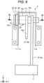
- Fig. 6 is a front view showing the pedal device 1 according to a third embodiment.
- Fig. 7 is a cross-sectional view taken along line VII-VII in Fig. 6 .
- an end portion 14d of the lever member 14 on an opposite side from the Y direction is positioned outside the two wall portions 11a and 11b, and a flange portion 14e is provided on the end portion 14d.
- the flange portion 14e is positioned outside the two wall portions 11a and 11b.
- the support member 16, the elastic body 17, the detection element 18, the pressing member 19, and the bearing 25 are positioned outside the two wall portions 11a and 11b and between the flange portion 14e and the wall portion 11a.
- the elastic body 17 and the detection element 18 are positioned outside the two wall portions 11a and 11b and fixed to the wall portion 11a.
- the lever member 14 and the lever member 15 relatively move in directions approaching each other in the axial direction by the operation force, and sandwich the wall portion 11a.
- the elastic body 17 and the detection element 18 are positioned outside the two wall portions 11a and 11b and fixed to the wall portion 11a.
- the wiring routing and the assembling workability of the detection element 18 are improved.
- Fig. 8 is a front view showing the pedal device 1 according to a fourth embodiment.
- Fig. 9 is a side view showing the pedal device 1 according to the fourth embodiment, and shows a state in which the pedal 2 is positioned at an initial position.
- Fig. 10 is a side view showing the pedal device 1 according to the fourth embodiment, and shows a state in which the pedal 2 is positioned at a maximum depression position.
- the present embodiment is different from the first embodiment in that the pedal device 1 includes a motor 50 as a reaction force generation device, a link mechanism 60, and a speed reduction mechanism 66.
- the pedal device 1 is disposed beside an accelerator pedal device 100.
- the link mechanism 60 is a parallel link. Specifically, the link mechanism 60 includes the lever member 14, a lever member 62, and a connection link 63.
- the pedal 2 is fixed to the connection link 63.
- One end portion 14m of the lever member 14 is supported by the support member 11 in a manner of being rotatable about the rotation center axis Ax1.
- the other end portion 14n of the lever member 14 is connected to the connection link 63 via a shaft 71 in a manner of being relatively rotatable about a rotation center axis Ax3 with respect to the connection link 63.
- One end portion 62m of the lever member 62 is supported by the support member 11 via a shaft 72 in a manner of being rotatable about a rotation center axis Ax2.
- the shaft 72 is provided with a rotation sensor that detects a rotation amount of the lever member 62.
- connection link 63 connects the other end portion 14n of the lever member 14 on an opposite side from the rotation center axis Ax1 and the other end portion 62n of the lever member 62 on an opposite side from the rotation center axis Ax2.
- the connection link 63 supports the pedal 2 such that the pedal 2 is movable in a direction orthogonal to the rotation center axis Ax1.
- the motor 50 includes a rotation shaft 51, and the rotation shaft 51 rotates about a rotation center axis Ax5. When power is supplied, the motor 50 generates a reaction force torque, which is a reaction force of the operation force, on the rotation shaft 51.
- the motor 50 is a motor with a brake capable of braking the rotation shaft 51.
- the speed reduction mechanism 66 is interposed between the lever member 14 and the rotation shaft 51.
- the speed reduction mechanism 66 includes the fan-shaped lever member 15 and gears 65 and 67.
- the lever member 15 is connected to the lever member 14 via the conversion mechanism 20.
- the lever member 15 rotates about the rotation center axis Ax1 in the same direction as the lever member 14 as the lever member 14 rotates.
- the lever member 15 is formed in the fan shape, and teeth 15i are provided on an arc-shaped edge portion 15h of the lever member 15. That is, the lever member 15 is a fan-shaped gear.
- the gear 65 is supported by the support member 11 in a manner of being rotatable about a rotation center axis Ax6.
- the gear 65 meshes with the lever member 15.
- the lever member 15 is fixed to the gear 65 and rotates about the rotation center axis Ax6 integrally with the gear 65.
- a diameter of the lever member 15 is larger than that of the gear 65.
- the number of teeth of the lever member 15 is larger than that of the gear 65.
- the lever member 15 meshes with a gear 51a provided on an outer peripheral surface of the rotation shaft 51 of the motor 50.
- the rotation center axes Ax1 to Ax6 are parallel to one another.
- the speed reduction mechanism 66 having the above-described configuration amplifies the reaction force torque of the rotation shaft 51 of the motor 50, converts the reaction force torque into a torque about the rotation center axis Ax1, and transmits the torque to the lever member 14. Accordingly, the motor 50 may be relatively small.
- the lever member 14 and the motor 50 are positioned on an opposite side from the pedal 2 with respect to the lever member 62.
- the rotation center axes Ax1, Ax2, and Ax5 are positioned below the pedal 2.
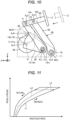
- Fig. 11 is a diagram showing a relationship between a reaction force and a pedal stroke under control of the motor 50 of the pedal device 1 according to the fourth embodiment.
- a horizontal axis in Fig. 11 indicates a magnitude of the reaction force generated by the motor 50, and a vertical axis in Fig. 11 indicates an amount of the stroke of the pedal 2.
- a line L1 in Fig. 11 indicates a sum of the reaction force generated by the motor on the rotation shaft 51 and a frictional force generated by the brake.
- a line L2 in Fig. 11 indicates the reaction force generated by the motor 50 on the rotation shaft 51, and a line L3 indicates a magnitude of the frictional force.
- the motor 50 is controlled by a control device so as to generate the reaction force indicated by the line L1 in Fig. 11 .
- the lever member 14 constitutes a link of the link mechanism 60 (parallel link). According to such a configuration, a movement trajectory of the pedal 2 is easily brought close to a straight line by the link mechanism 60 (parallel link).
Landscapes
- Engineering & Computer Science (AREA)
- Physics & Mathematics (AREA)
- General Physics & Mathematics (AREA)
- Automation & Control Theory (AREA)
- Transportation (AREA)
- Mechanical Engineering (AREA)
- Fluid Mechanics (AREA)
- Mechanical Control Devices (AREA)
- Braking Elements And Transmission Devices (AREA)
Abstract
Description
- This disclosure relates to an operation amount detection device.
- In related art, as an operation amount detection device that detects an operation amount of a pedal of a pedal device, a device is known in which a strain body serving as a detection element is provided on a reaction force member that is connected to the pedal device and that transmits a reaction force against an operation force of the pedal to the pedal device, and a strain amount of the strain body is detected.
- PTL 1:
JP2010-231367A - However, in the related art, since the strain body is provided on the reaction force member, there is a problem in that an arrangement of the strain body is restricted by a shape or the like of the reaction force member.
- An object of this disclosure is to provide an operation amount detection device in which an arrangement of a detection element is less likely to be restricted by a reaction force member.
- An operation amount detection device according to this disclosure includes: a first member configured to rotate about a rotation center axis by an operation force input to a pedal and transmit a rotation torque; a second member configured to receive, from a reaction force member, a reaction force of the rotation torque transmitted from the first member, the second member being rotatable about the rotation center axis and movable relative to the first member in an axial direction of the rotation center axis, and being interposed between the first member and the reaction force member; a conversion mechanism configured to convert rotation of the first member into a relative movement of the first member and the second member in the axial direction to convert the rotation torque into a thrust force which is a force in the axial direction; an elastic body provided apart from the reaction force member and configured to be elastically deformed by the thrust force; and a detection element fixed to the elastic body and configured to detect a deformation amount of the elastic body.
- According to such a configuration, since the detection element is fixed to the elastic body provided apart from the reaction force member, an arrangement of the detection element is less likely to be restricted by the reaction force member.
- In the operation amount detection device, for example, the elastic body and the detection element are positioned between the first member and the second member in the axial direction and rotate about the rotation center axis integrally with the first member or the second member.
- According to such a configuration, since the elastic body and the detection element rotate integrally with the first member or the second member about the rotation center axis, a configuration (bearing) of rotatably supporting the elastic body, the detection element, and the first member or the second member is easily simplified as compared with a configuration in which the elastic body and the detection element rotate separately from the first member and the second member.
- The operation amount detection device includes, for example, a support member including two wall portions that are apart from each other in the axial direction and that support the first member and the second member such that the first member and the second member are rotatable about the rotation center axis. The first member and the second member are positioned between the two wall portions, and relatively move in directions apart from each other in the axial direction by the operation force, and the first member is pressed against one of the wall portions.
- According to such a configuration, since the first member is pressed against the one of the wall portions, an occurrence of rattling of the first member in the axial direction is prevented.
- In the operation amount detection device, for example, the elastic body and the detection element are positioned between the two wall portions and fixed to the other one of the wall portions.
- According to such a configuration, wiring routing and assembling workability of the detection element are improved.
- The operation amount detection device includes a support member including two wall portions that are apart from each other in the axial direction and that support the first member and the second member such that the first member and the second member are rotatable about the rotation center axis. The first member and the second member relatively move in directions approaching each other in the axial direction by the operation force and sandwich one of the wall portions.
- According to such a configuration, since the first member and the second member sandwich the one of the wall portions, an occurrence of rattling of the first member and the second member in the axial direction is prevented.
- In the operation amount detection device, for example, the elastic body and the detection element are positioned outside the two wall portions and fixed to the one of the wall portions.
- According to such a configuration, the wiring routing and the assembling workability of the detection element are improved.
- In the operation amount detection device, for example, the first member constitutes a link of a parallel link.
- According to such a configuration, a movement trajectory of the pedal is easily brought close to a straight line by the parallel link.
-
- [
Fig. 1] Fig. 1 is a side view showing a pedal device according to a first embodiment. - [
Fig. 2] Fig. 2 is a front view showing the pedal device according to the first embodiment. - [
Fig. 3] Fig. 3 is a cross-sectional view taken along a line III-III inFig. 2 . - [
Fig. 4] Fig. 4 is a front view showing a pedal device according to a second embodiment. - [
Fig. 5] Fig. 5 is a cross-sectional view taken along a line V-V inFig. 4 . - [
Fig. 6] Fig. 6 is a front view showing a pedal device according to a third embodiment. - [
Fig. 7] Fig. 7 is a cross-sectional view taken along a line VII-VII inFig. 6 . - [
Fig. 8] Fig. 8 is a front view showing a pedal device according to a fourth embodiment. - [
Fig. 9] Fig. 9 is a side view showing the pedal device according to the fourth embodiment, and shows a state in which a pedal is positioned at an initial position. - [
Fig. 10] Fig. 10 is a side view showing the pedal device according to the fourth embodiment, and shows a state in which the pedal is positioned at a maximum depression position. - [
Fig. 11] Fig. 11 is a diagram showing a relationship between a reaction force and a pedal stroke under control of a motor of the pedal device according to the fourth embodiment. - Hereinafter, embodiments disclosed here will be described. Configurations (technical features) of the embodiments to be described below, and operations and results (effects) of the configurations are examples.
- The following plurality of embodiments include the same components. The same components are denoted by the same reference signs, and redundant description thereof is omitted. The drawings are schematic, and dimensional relationships of elements, ratios of elements, and the like may be different from actual ones. In addition, the drawings also include portions having different dimensional relationships and ratios from each other. In addition, in the present specification, an initial number is used only for distinguishing parts, members, portions, positions, directions, and the like, and does not indicate an order or priority.
-
Fig. 1 is a side view showing apedal device 1 according to a first embodiment.Fig. 2 is a front view showing thepedal device 1 according to the first embodiment. - The
pedal device 1 shown inFigs. 1 and2 is a brake pedal device mounted on a vehicle. It should be noted that thepedal device 1 may be an accelerator pedal device. - In the following description, for convenience, three directions orthogonal to one another are defined. An X direction corresponds to a front in a front-rear direction of the vehicle. AY direction corresponds to one side in a width direction of the vehicle. A Z direction corresponds to an upward direction in a vertical direction of the vehicle.
- The
pedal device 1 includes apedal 2 and an operationamount detection device 3. Thepedal 2 has, for example, a plate shape, and is subjected to a depression operation by an operator. The operationamount detection device 3 detects and outputs an operation amount of thepedal 2. -
Fig. 3 is a cross-sectional view taken along a line III-III inFig. 2 . As shown inFigs. 2 and3 , the operationamount detection device 3 includes asupport member 11, abolt 12, anut 13,lever members support member 16, anelastic body 17, adetection element 18, a pressing member 19, and aconversion mechanism 20. - The
support member 11 includes twowall portions 11a and 11b and aconnection wall portion 11c. The twowall portions 11a and 11b are apart from each other in the Y direction. In other words, the twowall portions 11a and 11b are apart from each other in an axial direction of a rotation center axis Ax1 extending in the Y direction. Thewall portions 11a and 11b are provided with through holes 11a1 and 11b1, respectively. Thewall portions 11a and 11b are fixed to a vehicle body of the vehicle. Theconnection wall portion 11c connects end portions of the twowall portions 11a and 11b in the Z direction. - As shown in
Fig. 3 , thebolt 12 extends in the axial direction of the rotation center axis Ax1 and is inserted into the through holes 11a1 and 11b1. Thebolt 12 is joined to thenut 13 and fixed to the twowall portions 11a and 11b. Thebolt 12 is inserted into acollar 27. - The
lever member 14 rotates about the rotation center axis Ax1 by an operation force input to thepedal 2, and transmits rotation torque. Specifically, thelever member 14 includes ashaft portion 14a and an arm portion 14b. Theshaft portion 14a is formed in a cylindrical shape about the rotation center axis Ax1. Thebolt 12 is inserted into theshaft portion 14a. Both end portions of theshaft portion 14a in the axial direction are rotatably supported bybearings helical spline 14c is formed on an outer peripheral surface of theshaft portion 14a. The arm portion 14b extends from theshaft portion 14a in a radial direction of the rotation center axis Ax1. Thepedal 2 is fixed to a tip end portion of the arm portion 14b. Thelever member 14 is an example of a first link. - The
lever member 15 is rotatable about the rotation center axis Ax1 and movable relative to thelever member 14 in the axial direction of the rotation center axis Ax1. Specifically, thelever member 15 includes ashaft portion 15a and an arm portion 15b. Theshaft portion 15a is formed in a cylindrical shape about the rotation center axis Ax1. Theshaft portion 15a of thelever member 14 is inserted into theshaft portion 15a. Ahelical spline 15c is formed on an inner peripheral surface of theshaft portion 15a. Thehelical spline 15c meshes with thehelical spline 14c. The arm portion 15b extends from theshaft portion 15a in the radial direction of the rotation center axis Ax1. Areaction force member 22 is connected to the tip end portion of the arm portion 14b via ashaft 26. Thereaction force member 22 is, for example, a crat screw. Thereaction force member 22 is connected to an operatingrod 21. Thereaction force member 22 inputs a reaction force against the rotation torque transmitted from thelever member 14 to thelever member 15. - The
conversion mechanism 20 includes theshaft portion 14a in which thehelical spline 14c is formed, and theshaft portion 15a in which thehelical spline 15c is formed. Theconversion mechanism 20 converts rotation of thelever member 14 into a relative movement between thelever member 14 and thelever member 15 in the axial direction, thereby converting the rotation torque into a thrust force which is a force in the axial direction. Specifically, theconversion mechanism 20 converts the rotation of thelever member 14 into a movement of the lever member in a direction in which the arm portion 14b of thelever member 14 and the arm portion 15b of thelever member 15 approach each other, thereby converting the rotation torque into the thrust force which is the force in the axial direction. - The
support member 16 is positioned between the arm portion 14b and the arm portion 15b. Thesupport member 11 is formed in a cylindrical shape about the rotation center axis Ax1. - The
elastic body 17 protrudes from an inner peripheral surface of thesupport member 16 toward the rotation center axis Ax1. Theelastic body 17 is formed in a circular plate shape about the rotation center axis Ax1. Theelastic body 17 is provided apart from thereaction force member 22. - The
detection element 18 is fixed to theelastic body 17 and detects a deformation amount (strain amount) of theelastic body 17. For example, a plurality ofdetection elements 18 are provided at intervals about the rotation center axis Ax1. Thedetection element 18 is, for example, a strain gauge. - The pressing member 19 is positioned between the arm portion 14b and the arm portion 15b inside the
support member 16. The pressing member 19 is formed in a tubular shape about the rotation center axis Ax1. The pressing member 19 has a pressing surface 19a inclined with respect to the rotation center axis Ax1, and presses a tip end portion of theelastic pair 17 in the axial direction by the pressing surface 19a. Abearing 25 is interposed between the pressing member 19 and the arm portion 15b, and the pressing member 19, theelastic body 17, and thedetection element 18 are rotatable relative to the arm portion 15b. The pressing member 19, theelastic body 17, and thedetection element 18 rotate integrally with the arm portion 14b (lever member 14). - In the above-described configuration, when the
pedal 2 is depressed, thelever member 14 rotates about the rotation center axis Ax1, and theconversion mechanism 20 converts the rotation of thelever member 14 into the relative movement in the axial direction between thelever member 14 and thelever member 15, thereby converting the rotation torque of thelever member 14 into the thrust force which is the force in the axial direction. At this time, thelever member 15 moves in the axial direction (Y direction) and presses theelastic body 17 in the axial direction via the pressing member 19. Accordingly, theelastic body 17 is elastically deformed. That is, theelastic body 17 is elastically deformed by the thrust force. Thedetection element 18 detects and outputs the deformation amount of theelastic body 17. The deformation amount of theelastic body 17 is an example of an operation amount of thepedal 2. Since the deformation amount of theelastic body 17 is in a proportional relationship with a depression force applied to thepedal 2, the depression force can be calculated based on information (formula or table) indicating a relationship between the deformation amount of theelastic body 17 and the depression force. - As described above, in the present embodiment, the operation
amount detection device 3 includes the lever member 14 (first member), the lever member 15 (second member), theconversion mechanism 20, theelastic body 17, and thedetection element 18. Thelever member 14 rotates about the rotation center axis Ax1 by the operation force input to thepedal 2, and transmits the rotation torque. Thelever member 15 is rotatable about the rotation center axis Ax1, is movable relative to thelever member 14 in the axial direction of the rotation center axis Ax1, and is interposed between thelever member 14 and thereaction force member 22, and the reaction force of the rotation torque transmitted from thelever member 14 is received from thereaction force member 22. Theconversion mechanism 20 converts the rotation of thelever member 14 into the relative movement between thelever member 14 and thelever member 15 in the axial direction, thereby converting the rotation torque into the thrust force which is the force in the axial direction. Theelastic body 17 is provided apart from thereaction force member 22 and elastically deformed by the thrust force. Thedetection element 18 is fixed to theelastic body 17 and detects the deformation amount of theelastic body 17. - According to such a configuration, since the
detection element 18 is fixed to theelastic body 17 provided apart from thereaction force member 22, an arrangement of thedetection element 18 is less likely to be restricted by thereaction force member 22. - The
elastic body 17 and thedetection element 18 are positioned between thelever member 14 and thelever member 15 in the axial direction and rotate about the rotation center axis Ax1 integrally with thelever member 14. - According to such a configuration, since the
elastic body 17 and thedetection element 18 rotate integrally with thelever member 14 about the rotation center axis Ax1, a configuration (bearing) of rotatably supporting theelastic body 17, thedetection element 18, and thelever member 14 is easily simplified as compared with a configuration in which theelastic body 17 and thedetection element 18 rotate separately from thelever member 14 and thelever member 15. - In the above description, as an example, the configuration is described in which the
elastic body 17 and thedetection element 18 are positioned between thelever member 14 and thelever member 15 in the axial direction and rotate about the rotation center axis Ax1 integrally with the arm portion 14b of the lever member 14 (first member), but the embodiment disclosed here is not limited thereto. Theelastic body 17 and thedetection element 18 may be positioned between thelever member 14 and thelever member 15 in the axial direction and rotate about the rotation center axis Ax1 integrally with the arm portion 15b of the lever member 15 (second member). According to such a configuration, since theelastic body 17 and thedetection element 18 rotate integrally with thelever member 15 about the rotation center axis Ax1, a configuration (bearing) of rotatably supporting theelastic body 17, thedetection element 18, and thelever member 15 is easily simplified as compared with the configuration in which theelastic body 17 and thedetection element 18 rotate separately from thelever member 14 and thelever member 15. -
Fig. 4 is a front view showing thepedal device 1 according to a second embodiment.Fig. 5 is a cross-sectional view taken along a line V-V inFig. 4 . - As shown in
Figs. 4 and5 , in the present embodiment, thelever member 14 and thelever member 15 are positioned between the twowall portions 11a and 11b, and relatively move in directions apart from each other in the axial direction by the operation force, and thelever member 14 is pressed against thewall portion 11b. - The
elastic body 17 and thedetection element 18 are positioned between the twowall portions 11a and 11b and fixed to the wall portion 11a. - As described above, in the present embodiment, the
lever member 14 and thelever member 15 are positioned between the twowall portions 11a and 11b, and relatively move in the directions apart from each other in the axial direction by the operation force, and thelever member 14 is pressed against thewall portion 11b. - According to such a configuration, since the
lever member 14 is pressed against thewall portion 11b, an occurrence of rattling of thelever member 14 in the axial direction is prevented. - The
elastic body 17 and thedetection element 18 are positioned between the twowall portions 11a and 11b and fixed to the wall portion 11a. - According to such a configuration, wiring routing and assembling workability of the
detection element 18 are improved. -
Fig. 6 is a front view showing thepedal device 1 according to a third embodiment.Fig. 7 is a cross-sectional view taken along line VII-VII inFig. 6 . - As shown in
Figs. 6 and7 , in the present embodiment, anend portion 14d of thelever member 14 on an opposite side from the Y direction is positioned outside the twowall portions 11a and 11b, and aflange portion 14e is provided on theend portion 14d. Theflange portion 14e is positioned outside the twowall portions 11a and 11b. - In the present embodiment, the
support member 16, theelastic body 17, thedetection element 18, the pressing member 19, and thebearing 25 are positioned outside the twowall portions 11a and 11b and between theflange portion 14e and the wall portion 11a. Theelastic body 17 and thedetection element 18 are positioned outside the twowall portions 11a and 11b and fixed to the wall portion 11a. - In the above configuration, the
lever member 14 and thelever member 15 relatively move in directions approaching each other in the axial direction by the operation force, and sandwich the wall portion 11a. - According to such a configuration, since the
lever member 14 and thelever member 15 sandwich the wall portion 11a, an occurrence of rattling of thelever member 14 and thelever member 15 in the axial direction is prevented. - The
elastic body 17 and thedetection element 18 are positioned outside the twowall portions 11a and 11b and fixed to the wall portion 11a. - According to such a configuration, the wiring routing and the assembling workability of the
detection element 18 are improved. -
Fig. 8 is a front view showing thepedal device 1 according to a fourth embodiment.Fig. 9 is a side view showing thepedal device 1 according to the fourth embodiment, and shows a state in which thepedal 2 is positioned at an initial position.Fig. 10 is a side view showing thepedal device 1 according to the fourth embodiment, and shows a state in which thepedal 2 is positioned at a maximum depression position. - As shown in
Figs. 8 to 10 , the present embodiment is different from the first embodiment in that thepedal device 1 includes amotor 50 as a reaction force generation device, alink mechanism 60, and a speed reduction mechanism 66. Thepedal device 1 is disposed beside anaccelerator pedal device 100. - The
link mechanism 60 is a parallel link. Specifically, thelink mechanism 60 includes thelever member 14, alever member 62, and aconnection link 63. - The
pedal 2 is fixed to theconnection link 63. Oneend portion 14m of thelever member 14 is supported by thesupport member 11 in a manner of being rotatable about the rotation center axis Ax1. Theother end portion 14n of thelever member 14 is connected to theconnection link 63 via ashaft 71 in a manner of being relatively rotatable about a rotation center axis Ax3 with respect to theconnection link 63. Oneend portion 62m of thelever member 62 is supported by thesupport member 11 via ashaft 72 in a manner of being rotatable about a rotation center axis Ax2. Theshaft 72 is provided with a rotation sensor that detects a rotation amount of thelever member 62. Theother end portion 62n of thelever member 62 is connected to theconnection link 63 via ashaft 73 in a manner of being relatively rotatable about a rotation center axis Ax4 with respect to theconnection link 63. That is, theconnection link 63 connects theother end portion 14n of thelever member 14 on an opposite side from the rotation center axis Ax1 and theother end portion 62n of thelever member 62 on an opposite side from the rotation center axis Ax2. Theconnection link 63 supports thepedal 2 such that thepedal 2 is movable in a direction orthogonal to the rotation center axis Ax1. - The
motor 50 includes arotation shaft 51, and therotation shaft 51 rotates about a rotation center axis Ax5. When power is supplied, themotor 50 generates a reaction force torque, which is a reaction force of the operation force, on therotation shaft 51. Themotor 50 is a motor with a brake capable of braking therotation shaft 51. - The speed reduction mechanism 66 is interposed between the
lever member 14 and therotation shaft 51. The speed reduction mechanism 66 includes the fan-shapedlever member 15 and gears 65 and 67. Thelever member 15 is connected to thelever member 14 via theconversion mechanism 20. Thelever member 15 rotates about the rotation center axis Ax1 in the same direction as thelever member 14 as thelever member 14 rotates. In the present embodiment, thelever member 15 is formed in the fan shape, andteeth 15i are provided on an arc-shapededge portion 15h of thelever member 15. That is, thelever member 15 is a fan-shaped gear. - The
gear 65 is supported by thesupport member 11 in a manner of being rotatable about a rotation center axis Ax6. Thegear 65 meshes with thelever member 15. Thelever member 15 is fixed to thegear 65 and rotates about the rotation center axis Ax6 integrally with thegear 65. A diameter of thelever member 15 is larger than that of thegear 65. The number of teeth of thelever member 15 is larger than that of thegear 65. Thelever member 15 meshes with a gear 51a provided on an outer peripheral surface of therotation shaft 51 of themotor 50. The rotation center axes Ax1 to Ax6 are parallel to one another. - The speed reduction mechanism 66 having the above-described configuration amplifies the reaction force torque of the
rotation shaft 51 of themotor 50, converts the reaction force torque into a torque about the rotation center axis Ax1, and transmits the torque to thelever member 14. Accordingly, themotor 50 may be relatively small. - The
lever member 14 and themotor 50 are positioned on an opposite side from thepedal 2 with respect to thelever member 62. The rotation center axes Ax1, Ax2, and Ax5 are positioned below thepedal 2. - In the above configuration, when the
pedal 2 is subjected to the depression operation, thepedal 2 moves in the direction orthogonal to the rotation center axis Ax1 while being supported by thelink mechanism 60. Due to deformation of thelink mechanism 60, thelever member 15 rotates about the rotation center axis Ax1, thegears 65 and 67 rotate about the rotation center axis Ax6, and the operation force of thepedal 2 is transmitted from thelever member 15 to therotation shaft 51 of themotor 50. -
Fig. 11 is a diagram showing a relationship between a reaction force and a pedal stroke under control of themotor 50 of thepedal device 1 according to the fourth embodiment. A horizontal axis inFig. 11 indicates a magnitude of the reaction force generated by themotor 50, and a vertical axis inFig. 11 indicates an amount of the stroke of thepedal 2. A line L1 inFig. 11 indicates a sum of the reaction force generated by the motor on therotation shaft 51 and a frictional force generated by the brake. A line L2 inFig. 11 indicates the reaction force generated by themotor 50 on therotation shaft 51, and a line L3 indicates a magnitude of the frictional force. Themotor 50 is controlled by a control device so as to generate the reaction force indicated by the line L1 inFig. 11 . - As described above, in the present embodiment, the
lever member 14 constitutes a link of the link mechanism 60 (parallel link). According to such a configuration, a movement trajectory of thepedal 2 is easily brought close to a straight line by the link mechanism 60 (parallel link). - While certain embodiments disclosed here have been described, these embodiments have been presented by way of example only, and are not intended to limit the scope of the disclosure. Novel embodiments can be implemented in various forms, and various omissions, substitutions, and modifications can be made without departing from the gist of the disclosure. The accompanying claims and their equivalents are intended to cover such embodiments or modifications as would fall within the scope and spirit of the disclosure.
-
- 2: pedal
- 3: operation amount detection device
- 11: support member
- 11a, 11b: wall portion
- 14: lever member (first member)
- 15: lever member (second member)
- 17: elastic body
- 18: detection element
- 20: conversion mechanism
- 22: reaction force member
- 60: link mechanism (parallel link)
- Ax1: rotation center axis
Claims (7)
- An operation amount detection device comprising:a first member configured to rotate about a rotation center axis by an operation force input to a pedal and transmit a rotation torque;a second member configured to receive, from a reaction force member, a reaction force of the rotation torque transmitted from the first member, the second member being rotatable about the rotation center axis and movable relative to the first member in an axial direction of the rotation center axis, and being interposed between the first member and the reaction force member;a conversion mechanism configured to convert rotation of the first member into a relative movement of the first member and the second member in the axial direction to convert the rotation torque into a thrust force which is a force in the axial direction;an elastic body provided apart from the reaction force member and configured to be elastically deformed by the thrust force; anda detection element fixed to the elastic body and configured to detect a deformation amount of the elastic body.
- The operation amount detection device according to claim 1, wherein
the elastic body and the detection element are positioned between the first member and the second member in the axial direction and rotate about the rotation center axis integrally with the first member or the second member. - The operation amount detection device according to claim 1, comprising:a support member including two wall portions that are apart from each other in the axial direction and that support the first member and the second member such that the first member and the second member are rotatable about the rotation center axis, whereinthe first member and the second member are positioned between the two wall portions, and relatively move in directions apart from each other in the axial direction by the operation force, and the first member is pressed against one of the wall portions.
- The operation amount detection device according to claim 3, wherein
the elastic body and the detection element are positioned between the two wall portions and fixed to the other one of the wall portions. - The operation amount detection device according to claim 1, comprising:a support member including two wall portions that are apart from each other in the axial direction and that support the first member and the second member such that the first member and the second member are rotatable about the rotation center axis, whereinthe first member and the second member relatively move in directions approaching each other in the axial direction by the operation force and sandwich one of the wall portions.
- The operation amount detection device according to claim 5, wherein
the elastic body and the detection element are positioned outside the two wall portions and fixed to the one of the wall portions. - The operation amount detection device according to any one of claims 1 to 6, wherein the first member constitutes a link of a parallel link.
Applications Claiming Priority (2)
| Application Number | Priority Date | Filing Date | Title |
|---|---|---|---|
| JP2021211493A JP7459860B2 (en) | 2021-12-24 | 2021-12-24 | Operation amount detection device |
| PCT/JP2022/031114 WO2023119723A1 (en) | 2021-12-24 | 2022-08-17 | Operation amount detection device |
Publications (3)
| Publication Number | Publication Date |
|---|---|
| EP4455827A1 true EP4455827A1 (en) | 2024-10-30 |
| EP4455827A4 EP4455827A4 (en) | 2025-03-26 |
| EP4455827B1 EP4455827B1 (en) | 2026-02-18 |
Family
ID=86901754
Family Applications (1)
| Application Number | Title | Priority Date | Filing Date |
|---|---|---|---|
| EP22910451.8A Active EP4455827B1 (en) | 2021-12-24 | 2022-08-17 | Operation amount detection device |
Country Status (5)
| Country | Link |
|---|---|
| US (1) | US12535846B2 (en) |
| EP (1) | EP4455827B1 (en) |
| JP (1) | JP7459860B2 (en) |
| CN (1) | CN118318217A (en) |
| WO (1) | WO2023119723A1 (en) |
Family Cites Families (6)
| Publication number | Priority date | Publication date | Assignee | Title |
|---|---|---|---|---|
| DE3703591A1 (en) * | 1987-02-06 | 1988-08-18 | Audi Ag | Device for producing an electric signal |
| JP5062211B2 (en) | 2009-03-26 | 2012-10-31 | トヨタ自動車株式会社 | Operation amount detection device |
| DE102012202632A1 (en) * | 2012-02-21 | 2013-08-22 | Robert Bosch Gmbh | Sensor arrangement for detecting angles of rotation on a rotating component in a vehicle |
| JP5619054B2 (en) * | 2012-03-07 | 2014-11-05 | 豊田鉄工株式会社 | Pedal operation amount detection device |
| JP2018141729A (en) * | 2017-02-28 | 2018-09-13 | 株式会社アドヴィックス | Tread force detection device |
| JP7136058B2 (en) * | 2019-10-08 | 2022-09-13 | トヨタ自動車株式会社 | Electromagnetic brake device |
-
2021
- 2021-12-24 JP JP2021211493A patent/JP7459860B2/en active Active
-
2022
- 2022-08-17 US US18/701,799 patent/US12535846B2/en active Active
- 2022-08-17 CN CN202280079096.8A patent/CN118318217A/en active Pending
- 2022-08-17 WO PCT/JP2022/031114 patent/WO2023119723A1/en not_active Ceased
- 2022-08-17 EP EP22910451.8A patent/EP4455827B1/en active Active
Also Published As
| Publication number | Publication date |
|---|---|
| WO2023119723A1 (en) | 2023-06-29 |
| CN118318217A (en) | 2024-07-09 |
| EP4455827A4 (en) | 2025-03-26 |
| US12535846B2 (en) | 2026-01-27 |
| US20250138569A1 (en) | 2025-05-01 |
| JP7459860B2 (en) | 2024-04-02 |
| JP2023095540A (en) | 2023-07-06 |
| EP4455827B1 (en) | 2026-02-18 |
Similar Documents
| Publication | Publication Date | Title |
|---|---|---|
| US8596163B2 (en) | Installation structure of a pedal stroke sensor | |
| JP4579279B2 (en) | Pedal operation amount detection device | |
| CN114641381B (en) | Drive device | |
| JP5429189B2 (en) | Operation amount detection device | |
| JP5499930B2 (en) | Electric brake device | |
| US10814854B2 (en) | Assembly having a brake cylinder and an electromechanical brake booster | |
| EP2266849A2 (en) | Pedal device for motor vehicle | |
| EP2343224B1 (en) | Vehicle operating pedal device | |
| JP2010269412A (en) | Robot equipment | |
| CN106061688A (en) | Safety systems for industrial robots | |
| CN104487301A (en) | Actuating device for a master brake cylinder of a motor vehicle | |
| US20050067889A1 (en) | Brake-by-wire input device arrangment | |
| JPWO2015049786A1 (en) | Accelerator pedal device for vehicle | |
| EP4455827B1 (en) | Operation amount detection device | |
| JP5062211B2 (en) | Operation amount detection device | |
| JP2023095541A (en) | pedal device | |
| JP2009108953A (en) | Clamp device for control cable in vehicle | |
| JP6670265B2 (en) | Operation pedal device for vehicles | |
| JP6920258B2 (en) | Vehicle operation pedal device | |
| WO2017221939A1 (en) | Electric brake apparatus | |
| WO2010109639A1 (en) | Operation amount detection device | |
| US10655713B2 (en) | Device having a pivot lever | |
| JP2014081061A (en) | Shift control device of manual transmission | |
| JP6807666B2 (en) | Electric brake device | |
| JP6190353B2 (en) | Retreat prevention device for vehicle pedal device |
Legal Events
| Date | Code | Title | Description |
|---|---|---|---|
| STAA | Information on the status of an ep patent application or granted ep patent |
Free format text: STATUS: THE INTERNATIONAL PUBLICATION HAS BEEN MADE |
|
| PUAI | Public reference made under article 153(3) epc to a published international application that has entered the european phase |
Free format text: ORIGINAL CODE: 0009012 |
|
| STAA | Information on the status of an ep patent application or granted ep patent |
Free format text: STATUS: REQUEST FOR EXAMINATION WAS MADE |
|
| 17P | Request for examination filed |
Effective date: 20240416 |
|
| AK | Designated contracting states |
Kind code of ref document: A1 Designated state(s): AL AT BE BG CH CY CZ DE DK EE ES FI FR GB GR HR HU IE IS IT LI LT LU LV MC MK MT NL NO PL PT RO RS SE SI SK SM TR |
|
| REG | Reference to a national code |
Free format text: PREVIOUS MAIN CLASS: G05G0001300000 Ipc: G05G0001380000 Ref country code: DE Ref legal event code: R079 Ref document number: 602022030879 Country of ref document: DE Free format text: PREVIOUS MAIN CLASS: G05G0001300000 Ipc: G05G0001380000 |
|
| A4 | Supplementary search report drawn up and despatched |
Effective date: 20250221 |
|
| RIC1 | Information provided on ipc code assigned before grant |
Ipc: B60T 7/02 20060101ALI20250218BHEP Ipc: G05G 1/44 20080401ALI20250218BHEP Ipc: G05G 1/38 20080401AFI20250218BHEP |
|
| DAV | Request for validation of the european patent (deleted) | ||
| DAX | Request for extension of the european patent (deleted) | ||
| GRAP | Despatch of communication of intention to grant a patent |
Free format text: ORIGINAL CODE: EPIDOSNIGR1 |
|
| STAA | Information on the status of an ep patent application or granted ep patent |
Free format text: STATUS: GRANT OF PATENT IS INTENDED |
|
| RIC1 | Information provided on ipc code assigned before grant |
Ipc: G05G 1/38 20080401AFI20250915BHEP Ipc: G05G 1/44 20080401ALI20250915BHEP Ipc: B60T 7/04 20060101ALI20250915BHEP Ipc: B60T 8/17 20060101ALI20250915BHEP |
|
| INTG | Intention to grant announced |
Effective date: 20251015 |
|
| GRAS | Grant fee paid |
Free format text: ORIGINAL CODE: EPIDOSNIGR3 |
|
| GRAA | (expected) grant |
Free format text: ORIGINAL CODE: 0009210 |
|
| STAA | Information on the status of an ep patent application or granted ep patent |
Free format text: STATUS: THE PATENT HAS BEEN GRANTED |
|
| AK | Designated contracting states |
Kind code of ref document: B1 Designated state(s): AL AT BE BG CH CY CZ DE DK EE ES FI FR GB GR HR HU IE IS IT LI LT LU LV MC MK MT NL NO PL PT RO RS SE SI SK SM TR |
|
| REG | Reference to a national code |
Ref country code: CH Ref legal event code: F10 Free format text: ST27 STATUS EVENT CODE: U-0-0-F10-F00 (AS PROVIDED BY THE NATIONAL OFFICE) Effective date: 20260218 Ref country code: GB Ref legal event code: FG4D |
|
| REG | Reference to a national code |
Ref country code: IE Ref legal event code: FG4D |
|
| REG | Reference to a national code |
Ref country code: DE Ref legal event code: R096 Ref document number: 602022030879 Country of ref document: DE |
|
| REG | Reference to a national code |
Ref country code: NL Ref legal event code: MP Effective date: 20260218 |
|
| PG25 | Lapsed in a contracting state [announced via postgrant information from national office to epo] |
Ref country code: RS Free format text: LAPSE BECAUSE OF FAILURE TO SUBMIT A TRANSLATION OF THE DESCRIPTION OR TO PAY THE FEE WITHIN THE PRESCRIBED TIME-LIMIT Effective date: 20260518 |
|
| PG25 | Lapsed in a contracting state [announced via postgrant information from national office to epo] |
Ref country code: ES Free format text: LAPSE BECAUSE OF FAILURE TO SUBMIT A TRANSLATION OF THE DESCRIPTION OR TO PAY THE FEE WITHIN THE PRESCRIBED TIME-LIMIT Effective date: 20260218 |
|
| PG25 | Lapsed in a contracting state [announced via postgrant information from national office to epo] |
Ref country code: PL Free format text: LAPSE BECAUSE OF FAILURE TO SUBMIT A TRANSLATION OF THE DESCRIPTION OR TO PAY THE FEE WITHIN THE PRESCRIBED TIME-LIMIT Effective date: 20260218 |
|
| PG25 | Lapsed in a contracting state [announced via postgrant information from national office to epo] |
Ref country code: GR Free format text: LAPSE BECAUSE OF FAILURE TO SUBMIT A TRANSLATION OF THE DESCRIPTION OR TO PAY THE FEE WITHIN THE PRESCRIBED TIME-LIMIT Effective date: 20260519 |
|
| REG | Reference to a national code |
Ref country code: LT Ref legal event code: MG9D |
|
| PG25 | Lapsed in a contracting state [announced via postgrant information from national office to epo] |
Ref country code: LT Free format text: LAPSE BECAUSE OF FAILURE TO SUBMIT A TRANSLATION OF THE DESCRIPTION OR TO PAY THE FEE WITHIN THE PRESCRIBED TIME-LIMIT Effective date: 20260218 |
|
| PG25 | Lapsed in a contracting state [announced via postgrant information from national office to epo] |
Ref country code: NO Free format text: LAPSE BECAUSE OF FAILURE TO SUBMIT A TRANSLATION OF THE DESCRIPTION OR TO PAY THE FEE WITHIN THE PRESCRIBED TIME-LIMIT Effective date: 20260518 |
|
| PG25 | Lapsed in a contracting state [announced via postgrant information from national office to epo] |
Ref country code: FI Free format text: LAPSE BECAUSE OF FAILURE TO SUBMIT A TRANSLATION OF THE DESCRIPTION OR TO PAY THE FEE WITHIN THE PRESCRIBED TIME-LIMIT Effective date: 20260218 Ref country code: AT Free format text: LAPSE BECAUSE OF FAILURE TO SUBMIT A TRANSLATION OF THE DESCRIPTION OR TO PAY THE FEE WITHIN THE PRESCRIBED TIME-LIMIT Effective date: 20260218 Ref country code: SE Free format text: LAPSE BECAUSE OF FAILURE TO SUBMIT A TRANSLATION OF THE DESCRIPTION OR TO PAY THE FEE WITHIN THE PRESCRIBED TIME-LIMIT Effective date: 20260218 |
|
| REG | Reference to a national code |
Ref country code: AT Ref legal event code: MK05 Ref document number: 1888771 Country of ref document: AT Kind code of ref document: T Effective date: 20260218 |
|
| PG25 | Lapsed in a contracting state [announced via postgrant information from national office to epo] |
Ref country code: HR Free format text: LAPSE BECAUSE OF FAILURE TO SUBMIT A TRANSLATION OF THE DESCRIPTION OR TO PAY THE FEE WITHIN THE PRESCRIBED TIME-LIMIT Effective date: 20260218 |
|
| PG25 | Lapsed in a contracting state [announced via postgrant information from national office to epo] |
Ref country code: IS Free format text: LAPSE BECAUSE OF FAILURE TO SUBMIT A TRANSLATION OF THE DESCRIPTION OR TO PAY THE FEE WITHIN THE PRESCRIBED TIME-LIMIT Effective date: 20260618 Ref country code: PT Free format text: LAPSE BECAUSE OF FAILURE TO SUBMIT A TRANSLATION OF THE DESCRIPTION OR TO PAY THE FEE WITHIN THE PRESCRIBED TIME-LIMIT Effective date: 20260618 |
|
| PG25 | Lapsed in a contracting state [announced via postgrant information from national office to epo] |
Ref country code: NL Free format text: LAPSE BECAUSE OF FAILURE TO SUBMIT A TRANSLATION OF THE DESCRIPTION OR TO PAY THE FEE WITHIN THE PRESCRIBED TIME-LIMIT Effective date: 20260218 |
|
| PG25 | Lapsed in a contracting state [announced via postgrant information from national office to epo] |
Ref country code: LV Free format text: LAPSE BECAUSE OF FAILURE TO SUBMIT A TRANSLATION OF THE DESCRIPTION OR TO PAY THE FEE WITHIN THE PRESCRIBED TIME-LIMIT Effective date: 20260218 |
|
| PG25 | Lapsed in a contracting state [announced via postgrant information from national office to epo] |
Ref country code: BG Free format text: LAPSE BECAUSE OF FAILURE TO SUBMIT A TRANSLATION OF THE DESCRIPTION OR TO PAY THE FEE WITHIN THE PRESCRIBED TIME-LIMIT Effective date: 20260218 |