EP4455758A1 - Optical device and sensor device - Google Patents
Optical device and sensor device Download PDFInfo
- Publication number
- EP4455758A1 EP4455758A1 EP21969003.9A EP21969003A EP4455758A1 EP 4455758 A1 EP4455758 A1 EP 4455758A1 EP 21969003 A EP21969003 A EP 21969003A EP 4455758 A1 EP4455758 A1 EP 4455758A1
- Authority
- EP
- European Patent Office
- Prior art keywords
- light
- receiving area
- frame body
- emitting element
- movable reflection
- Prior art date
- Legal status (The legal status is an assumption and is not a legal conclusion. Google has not performed a legal analysis and makes no representation as to the accuracy of the status listed.)
- Pending
Links
Images



Classifications
-
- G—PHYSICS
- G02—OPTICS
- G02B—OPTICAL ELEMENTS, SYSTEMS OR APPARATUS
- G02B26/00—Optical devices or arrangements for the control of light using movable or deformable optical elements
- G02B26/08—Optical devices or arrangements for the control of light using movable or deformable optical elements for controlling the direction of light
- G02B26/10—Scanning systems
- G02B26/105—Scanning systems with one or more pivoting mirrors or galvano-mirrors
-
- G—PHYSICS
- G01—MEASURING; TESTING
- G01S—RADIO DIRECTION-FINDING; RADIO NAVIGATION; DETERMINING DISTANCE OR VELOCITY BY USE OF RADIO WAVES; LOCATING OR PRESENCE-DETECTING BY USE OF THE REFLECTION OR RERADIATION OF RADIO WAVES; ANALOGOUS ARRANGEMENTS USING OTHER WAVES
- G01S7/00—Details of systems according to groups G01S13/00, G01S15/00, G01S17/00
- G01S7/48—Details of systems according to groups G01S13/00, G01S15/00, G01S17/00 of systems according to group G01S17/00
- G01S7/481—Constructional features, e.g. arrangements of optical elements
- G01S7/4811—Constructional features, e.g. arrangements of optical elements common to transmitter and receiver
- G01S7/4813—Housing arrangements
-
- G—PHYSICS
- G01—MEASURING; TESTING
- G01S—RADIO DIRECTION-FINDING; RADIO NAVIGATION; DETERMINING DISTANCE OR VELOCITY BY USE OF RADIO WAVES; LOCATING OR PRESENCE-DETECTING BY USE OF THE REFLECTION OR RERADIATION OF RADIO WAVES; ANALOGOUS ARRANGEMENTS USING OTHER WAVES
- G01S7/00—Details of systems according to groups G01S13/00, G01S15/00, G01S17/00
- G01S7/48—Details of systems according to groups G01S13/00, G01S15/00, G01S17/00 of systems according to group G01S17/00
- G01S7/481—Constructional features, e.g. arrangements of optical elements
- G01S7/4817—Constructional features, e.g. arrangements of optical elements relating to scanning
-
- G—PHYSICS
- G01—MEASURING; TESTING
- G01S—RADIO DIRECTION-FINDING; RADIO NAVIGATION; DETERMINING DISTANCE OR VELOCITY BY USE OF RADIO WAVES; LOCATING OR PRESENCE-DETECTING BY USE OF THE REFLECTION OR RERADIATION OF RADIO WAVES; ANALOGOUS ARRANGEMENTS USING OTHER WAVES
- G01S7/00—Details of systems according to groups G01S13/00, G01S15/00, G01S17/00
- G01S7/48—Details of systems according to groups G01S13/00, G01S15/00, G01S17/00 of systems according to group G01S17/00
- G01S7/497—Means for monitoring or calibrating
-
- G—PHYSICS
- G02—OPTICS
- G02B—OPTICAL ELEMENTS, SYSTEMS OR APPARATUS
- G02B26/00—Optical devices or arrangements for the control of light using movable or deformable optical elements
- G02B26/08—Optical devices or arrangements for the control of light using movable or deformable optical elements for controlling the direction of light
-
- G—PHYSICS
- G02—OPTICS
- G02B—OPTICAL ELEMENTS, SYSTEMS OR APPARATUS
- G02B26/00—Optical devices or arrangements for the control of light using movable or deformable optical elements
- G02B26/08—Optical devices or arrangements for the control of light using movable or deformable optical elements for controlling the direction of light
- G02B26/0816—Optical devices or arrangements for the control of light using movable or deformable optical elements for controlling the direction of light by means of one or more reflecting elements
-
- G—PHYSICS
- G02—OPTICS
- G02B—OPTICAL ELEMENTS, SYSTEMS OR APPARATUS
- G02B26/00—Optical devices or arrangements for the control of light using movable or deformable optical elements
- G02B26/08—Optical devices or arrangements for the control of light using movable or deformable optical elements for controlling the direction of light
- G02B26/10—Scanning systems
Definitions
- the present invention relates to an optical device and a sensor device.
- the optical device may have a micro-electro mechanical system (MEMS) mirror that reflects light emitted from a light-emitting element such as a laser diode (LD) .
- MEMS micro-electro mechanical system
- the MEMS mirror may be provided with a piezo-resistance element that detects a swing of the MEMS mirror.
- Patent Document 1 Japanese Unexamined Patent Publication No. 2014-56211
- the present inventors have studied to attach a light-emitting element to a movable reflection body instead of a piezo-resistance element or in addition to the piezo-resistance element in order to detect a swing of a movable reflection body such as a MEMS mirror.
- the swing of the movable reflection body is detected by allowing a light-receiving element such as a four-segment photodiode (PD) to receive light emitted from a light-emitting element.
- the light-receiving element may be irradiated with light different from the light emitted from the light-emitting element, such as external light. Therefore, there is room for improvement in the accuracy of detection of the swing of the movable reflection body.
- One example of problems to be solved by the present invention may be to accurately detect a swing of a movable reflection body.
- the invention as described in Claim 1 is an optical device including:
- the invention as described in Claim 6 is a sensor device including:
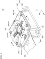
- Fig. 1 is a perspective view of an optical device 10 according to an embodiment.
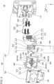
- Fig. 2 is an exploded perspective view of the optical device 10 according to the embodiment.
- Fig. 3 is a cross-sectional view taken along line A-A of Fig. 1 .
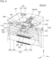
- Fig. 4 is a cross-sectional view taken along line B-B of Fig. 1 .
- Fig. 5 is a cross-sectional view taken along line C-C in Fig. 1 .
- an arrow indicating a first direction X, a second direction Y, or a third direction Z indicates that a direction from a proximal end toward a distal end of the arrow is a positive direction in the direction indicated by the arrow, and that a direction from the distal end toward the proximal end of the arrow is a negative direction in the direction indicated by the arrow.
- an X-marked circle indicating the third direction Z indicates that a direction from the foreground to the background of a paper plane is a positive direction in the third direction Z and that a direction from the background to the foreground of the paper plane is a negative direction in the third direction Z.
- the first direction X, the second direction Y, and the third direction Z are orthogonal to each other.
- the optical device 10 includes a housing body 100, an optical scanning device 200, a first light-emitting element 300, a first light-receiving element 400, a flexible substrate 500, a first magnetic circuit 610, a second magnetic circuit 620, and a heat sink 630.
- the housing body 100 has a base 102 and a lid 104.
- the optical scanning device 200 includes a movable reflection body 210, a first frame body 220, a pair of first torsion bars 230, a second frame body 240, a pair of second torsion bars 250, a first terminal 262, and a second terminal 264.
- the pair of first torsion bars 230 include a first metal bar 232 and a second metal bar 234.
- the pair of second torsion bars 250 includes a third metal bar 252 and a fourth metal bar 254.
- the positive direction in the first direction X is a direction from a side where the second metal bar 234 is positioned toward a side where the first metal bar 232 is positioned.
- the negative direction in the first direction X is a direction from the side where the first metal bar 232 is positioned toward the side where the second metal bar 234 is positioned.
- the positive direction in the second direction Y is a direction from a side where the fourth metal bar 254 is positioned toward a side where the third metal bar 252 is positioned.
- the negative direction in the second direction Y is a direction from the side where the third metal bar 252 is positioned toward the side where the fourth metal bar 254 is positioned.
- the positive direction in the third direction Z is a direction from a side where the base 102 is positioned toward a side where the lid 104 is positioned.
- the negative direction in the third direction Z is a direction from the side where the lid 104 is positioned toward the side where the base 102 is positioned.
- the housing body 100 houses the optical scanning device 200, the first light-emitting element 300, the first light-receiving element 400, at least a portion of the flexible substrate 500, the first magnetic circuit 610, the second magnetic circuit 620, and the heat sink 630.
- the lid 104 is attached onto a surface of the base 102 on the positive direction side in the third direction Z.
- At least a portion of the movable reflection body 210, at least a portion of the first frame body 220, and at least a portion of the pair of first torsion bars 230 are mounted on a surface side of the base 102 in the positive direction in the third direction Z in a state of being exposed from the opening 150 of the lid 104.
- at least a portion of the second frame body 240 and at least a portion of the pair of second torsion bars 250 are covered with the lid 104, as viewed from the positive direction in the third direction Z.
- the first light-receiving element 400 it is possible to make it difficult for the first light-receiving element 400 to be irradiated with external light, as compared with a case where at least a portion of the second frame body 240 and at least a portion of the pair of second torsion bars 250 are exposed from the lid 104, as viewed from the third direction Z.
- the reflected light from the second torsion bar 250 can be suppressed from returning to the light-receiving element for distance measurement, provided outside the optical scanning device 200, even in a case where a metal portion with a relatively high reflectance of the second torsion bar 250 is irradiated with diffusely reflected light from the outside of the optical scanning device 200 inside the housing body 100, as compared with a case where at least a portion of the pair of second torsion bars 250 is exposed from the lid 104.
- the movable reflection body 210 has a movable support table 212 and a reflection body 214.
- the movable support table 212 includes a first metal body 212a, a second metal body 212b, and a resin part 212c. At least a portion of the first metal body 212a is positioned on the positive direction side in the first direction X with respect to at least a portion of the second metal body 212b. At least a portion of the second metal body 212b is positioned on the negative direction side in the first direction X with respect to at least a portion of the first metal body 212a.
- the resin part 212c covers at least a portion of a surface of the first metal body 212a on the positive direction side in the third direction Z and at least a portion of a surface of the second metal body 212b on the positive direction side in the third direction Z.
- the reflection body 214 is positioned on a surface side of the resin part 212c in the positive direction in the third direction Z.
- the surface of the reflection body 214 on the positive direction side in the third direction Z is a reflection surface that reflects light from the outside of the optical scanning device 200, such as distance measurement light.
- the reflection body 214 is swingable together with the movable support table 212.
- the first frame body 220 includes a first metal frame body 222 and a first resin body 224.
- the first metal frame body 222 is positioned in at least a portion of a region surrounding the movable reflection body 210 and the pair of first torsion bars 230, as viewed from the third direction Z. At least a portion of the first metal frame body 222 is sealed by the first resin body 224. In a case where the first resin body 224 is provided, an unnecessary vibration of the first frame body 220 can be suppressed, as compared to a case where the first resin body 224 is not provided.
- the first metal bar 232 connects the movable reflection body 210 and the first frame body 220.
- the first metal bar 232 extends parallel to the first direction X.
- an end of the first metal bar 232 on the negative direction side in the first direction X is connected to the first metal body 212a.
- An end of the first metal bar 232 on the positive direction side in the first direction X is connected to an inner edge of the end of the first metal frame body 222 on the positive direction side in the first direction X.
- the second metal bar 234 connects the movable reflection body 210 and the first frame body 220.
- the second metal bar 234 extends parallel to the first direction X.
- an end of the second metal bar 234 on the positive direction side in the first direction X is connected to the second metal body 212b.
- An end of the second metal bar 234 on the negative direction side in the first direction X is connected to an inner edge of the end of the first metal frame body 222 on the negative direction side in the first direction X.
- a first permanent magnet 216 is provided on a surface side of the movable reflection body 210 in the negative direction in the third direction Z.
- the first permanent magnet 216 is positioned on the negative direction side in the first direction X with respect to the center of the movable reflection body 210 in the first direction X.
- the movable reflection body 210 swings with respect to the first frame body 220 using the pair of first torsion bars 230 as a rotation axis by allowing the first permanent magnet 216 to receive a magnetic flux generated from the first magnetic circuit 610.
- the first magnetic circuit 610 includes a first coil 612, a first yoke 614, and a pair of second yokes 616.
- the first coil 612 is wound around the first yoke 614.
- the first yoke 614 extends parallel to the second direction Y in the space on the negative direction side in the third direction Z with respect to the first light-emitting element 300 and the flexible substrate 500.
- Each of the pair of second yokes 616 is connected to each of an end of the first yoke 614 on the positive direction side in the second direction Y and an end of the first yoke 614 on the negative direction side in the second direction Y. As shown in Fig. 4 , each tip of the pair of second yokes 616 faces each other through a space positioned on the negative direction side in the third direction Z with respect to the movable reflection body 210.
- the movable reflection body 210 swings with respect to the first frame body 220 using the pair of first torsion bars 230 as a rotation axis by allowing the first permanent magnet 216 to receive the alternating current magnetic field.
- the second frame body 240 includes a second metal frame body 242 and a second resin body 244.
- the second metal frame body 242 is positioned in at least a portion of a region surrounding the first frame body 220 and the pair of second torsion bars 250, as viewed from the third direction Z. At least a portion of the second metal frame body 242 is sealed by the second resin body 244. In a case where the second resin body 244 is provided, an unnecessary vibration of the second frame body 240 can be suppressed, as compared to a case where the second resin body 244 is not provided.
- the third metal bar 252 connects the first frame body 220 and the second frame body 240.
- the third metal bar 252 extends parallel to the second direction Y.
- an end of the third metal bar 252 on the negative direction side in the second direction Y is connected to the part of the outer edge of the first metal frame body 222 that corresponds to the positive side of the second direction Y and the center of the first direction X.
- An end of the third metal bar 252 on the positive direction side in the second direction Y is connected to the part of the inner edge of the second metal frame body 242 that corresponds to the positive side of the second direction Y and the center of the first direction X.
- the fourth metal bar 254 connects the first frame body 220 and the second frame body 240.
- the fourth metal bar 254 extends parallel to the second direction Y.
- an end of the fourth metal bar 254 on the positive direction side in the second direction Y connected to the part of the outer edge of the first metal frame body 222 that corresponds to the negative side of the second direction Y and the center of the first direction X.
- An end of the fourth metal bar 254 on the negative direction side in the second direction Y is connected to the part of the inner edge of the second metal frame body 242 that corresponds to the negative side of the second direction Y and the center of the first direction X.
- each of the pair of second permanent magnets 226 is provided at each of both ends of the first frame body 220 in the first direction X.
- each of the second permanent magnets 226 is provided on a surface side of the first frame body 220 in the negative direction in the third direction Z.
- the first frame body 220 swings with respect to the second frame body 240 using the pair of second torsion bars 250 as a rotation axis by allowing each of the pair of second permanent magnets 226 to receive a magnetic flux generated from the second magnetic circuit 620.
- the movable reflection body 210 is integrated with the first frame body 220 and the pair of first torsion bars 230 to swing with respect to the second frame body 240 using the second torsion bar 250 as a rotation axis.
- the second magnetic circuit 620 includes one pair of second coils 622 positioned on the positive direction side in the first direction X and the other pair of second coils 622 positioned on the negative direction side in the first direction X.
- the pair of second coils 622 positioned on the positive direction side in the first direction X face each other through the end part of the first frame body 220 on the positive direction side in the first direction X.
- the other pair of second coils 622 positioned on the negative direction side in the first direction X face each other through the end part of the movable reflection body 210 on the negative direction side in the first direction X.
- an alternating current magnetic field is generated from the other pair of second coils 622.
- the first frame body 220 swings with respect to the second frame body 240 using the pair of second frame bodies 240 as a rotation axis by allowing the second permanent magnet 226 provided at each of both ends of the first frame body 220 in the first direction X to receive the alternating magnetic field.
- the movable reflection body 210 is integrated with the first frame body 220 and the pair of first torsion bars 230 to swing with respect to the second frame body 240 using the second torsion bar 250 as a rotation axis.
- each of the four second coils 622 is covered with the lid 104, as viewed from the positive direction in the third direction Z. Accordingly, the reflected light from the second coil 622 can be suppressed from returning to the light-receiving element for distance measurement, provided outside the optical scanning device 200, even in a case where a metal portion with a relatively high reflectance of the second coil 622 is irradiated with diffusely reflected light from the outside of the optical scanning device 200 inside the housing body 100, as compared with a case where at least a portion of each second coil 622 is exposed from the lid 104.
- the lid 104 covers a metal portion with a relatively high reflectance, such as a wiring that connects the flexible substrate 500 and the first coil 612, a soldering portion between the wiring and the flexible substrate 500, a wiring that connects the flexible substrate 500 and the second coil 622, and a soldering portion between the wiring and the flexible substrate 500, as viewed from the positive direction in the third direction Z. Accordingly, the reflected light from the metal portion can be suppressed from returning to the light-receiving element for distance measurement, provided outside the optical scanning device 200, even in a case where the metal portion is irradiated with the diffusely reflected light, as compared with a case where the metal portion is not covered with the lid 104.
- a metal portion with a relatively high reflectance such as a wiring that connects the flexible substrate 500 and the first coil 612, a soldering portion between the wiring and the flexible substrate 500, a wiring that connects the flexible substrate 500 and the second coil 622, and a soldering portion between the wiring and
- heat generated from the second magnetic circuit 620 is transferred to the heat sink 630 through a heat transfer agent which is not shown in the drawing.
- the heat generated from the second magnetic circuit 620 can be released to the outside of the optical device 10.
- the first terminal 262 and the second terminal 264 are connected to the second metal frame body 242. Specifically, as shown in Fig. 5 , the first terminal 262 is connected to the part of the outer edge of the second metal frame body 242 that corresponds to the positive side of the second direction Y and the center of the first direction X. The second terminal 264 is connected to the part of the outer edge of the second metal frame body 242 that corresponds to the positive side of the second direction Y and the part shifted to the positive direction side in the second direction Y from center of the first direction X. It should be noted that a position where the first terminal 262 and the second terminal 264 are provided is not limited to this example.
- the first terminal 262 and the second terminal 264 are pressed against the flexible substrate 500 by the lid 104. Accordingly, it is easier to ensure continuity between the first terminal 262 and the flexible substrate 500, and a conduction between the second terminal 264 and the flexible substrate 500, as compared with a case where the first terminal 262 and the second terminal 264 are not pressed against the flexible substrate 500 by the lid 104.
- the first light-emitting element 300 is, for example, a light-emitting diode (LED).
- the first light-emitting element 300 is attached onto the negative direction side in the third direction Z of the movable support table 212. Accordingly, the first light-emitting element 300 is swingable together with the movable reflection body 210.
- One of the anode and the cathode of the first light-emitting element 300 is electrically connected to the first metal body 212a.
- the other of the anode and the cathode of the first light-emitting element 300 is electrically connected to the second metal body 212b.
- the drive current of the first light-emitting element 300 can flow between the first terminal 262 and the second terminal 264.
- the first metal frame body 222 is provided with two first split parts 222a.
- One of the two first split parts 222a is provided between a connection part between the first metal frame body 222 and the first metal bar 232, and a connection part between the first metal frame body 222 and the fourth metal bar 254.
- the other of the two first split parts 222a is provided between a connection part between the first metal frame body 222 and the second metal bar 234, and a connection part between the first metal frame body 222 and the third metal bar 252.
- an occurrence of a short circuit between the first metal body 212a and the second metal body 212b through the first metal frame body 222 is prevented.
- an occurrence of a short circuit between the third metal bar 252 and the fourth metal bar 254 through the first metal frame body 222 is prevented.
- the second metal frame body 242 includes a second split part 242a on the positive direction side in the second direction Y of the second metal frame body 242, and another second split part 242a on the negative direction side in the second direction Y of the second metal frame body 242.
- the second split part 242a on the positive direction side in the second direction Y of the second metal frame body 242 is provided in a portion of the second metal frame body 242 which is corresponds to the positive side of the second direction Y and the part shifted to the negative direction side in the first direction X from the center part in the first direction X.
- the second split part 242a on the positive direction side in the second direction Y of the second metal frame body 242 is positioned between a connection part between the second metal frame body 242 and the first terminal 262, and a connection part between the second metal frame body 242 and the second terminal 264.
- the other second split part 242a on the negative direction side in the second direction Y of the second metal frame body 242 is provided in a portion of the second metal frame body 242 which is corresponds to the negative side of the second direction Y and the part shifted to the positive direction side in the first direction X from the center part in the first direction X.
- the drive current of the first light-emitting element 300 can flow from the first terminal 262 to the second terminal 264, through the third metal bar 252, a portion between a connection part between the first metal frame body 222 and the third metal bar 252, and a connection part between the first metal frame body 222 and the first metal bar 232 in the first metal frame body 222; a portion between a connection part between the first metal frame body 222 and the second metal bar 234, and a connection part between the first metal frame body 222 and the fourth metal bar 254 in the first metal bar 232, the first metal body 212a, the first light-emitting element 300, the second metal body 212b, the second metal bar 234, and the first metal frame body 222; and a portion between a connection part between the second metal frame body 242 and the fourth metal bar 254, and a connection part between the second metal frame body 242 and the second terminal 264 in the fourth metal bar 254 and the fourth metal frame body 242.
- the drive current flows from the first terminal 262
- the first light-receiving element 400 is positioned on the negative direction side in the third direction Z with respect to the first light-emitting element 300. At least a portion of the light-shielding body 110 of the base 102 is positioned between the first light-emitting element 300 and the first light-receiving element 400 in the third direction Z.
- the light-shielding body 110 defines an aperture 112. At least a portion of light emitted from the first light-emitting element 300 passes through the aperture 112.
- the first light-receiving element 400 receives light having passed through the aperture 112.
- the aperture 112 includes a narrow hole 114 and a wide hole 116.
- the narrow hole 114 penetrates a surface of the light-shielding body 110 on the positive direction side in the third direction Z.
- the inner surface of the narrow hole 114 is substantially parallel to the third direction Z.
- the opening area of the narrow hole 114 which is perpendicular to the third direction Z, is constant regardless of the position in the third direction Z.
- the wide hole 116 penetrates a surface of the light-shielding body 110 on the negative direction side in the third direction Z.
- An end of the wide hole 116 on the positive direction side in the third direction Z communicates with an end of the narrow hole 114 on the negative direction side in the third direction Z.
- the opening area of the wide hole 116, which is perpendicular to the third direction Z, is larger than the opening area of the narrow hole 114, which is perpendicular to the third direction Z.
- the inner surface of the wide hole 116 is a surface inclined with respect to the third direction Z.
- the opening area of the wide hole 116, which is perpendicular to the third direction Z increases from the positive direction to the negative direction in the third direction Z.
- the shape of the aperture 112 is not limited to the examples shown in Figs. 3 and 4 .
- the inner surface of the wide hole 116 may be substantially parallel to the third direction Z. In this case, the opening area of the wide hole 116, which is perpendicular to the third direction Z, is constant regardless of the position in the third direction Z.
- the first light-receiving element 400 is, for example, a four-segment PD (photodiode). As shown in Figs. 2 , 3 , and 4 , a surface of the first light-receiving element 400 on the positive direction side in the third direction Z has a light-receiving area 410.
- the light-receiving area 410 includes a first light-receiving area 412, a second light-receiving area 414, a third light-receiving area 416, and a fourth light-receiving area 418.
- the first light-receiving area 412, the second light-receiving area 414, the third light-receiving area 416, and the fourth light-receiving area 418 are segmented from each other.
- the first light-receiving area 412 is positioned on the positive direction side in the first direction X and on the positive direction side in the second direction Y with respect to the center of the light-receiving area 410 in the first direction X and the second direction Y.
- the second light-receiving area 414 is positioned on the negative direction side in the first direction X and on the positive direction side in the second direction Y with respect to the center of the light-receiving area 410 in the first direction X and the second direction Y.
- the third light-receiving area 416 is positioned on the negative direction side in the first direction X and on the negative direction side in the second direction Y with respect to the center of the light-receiving area 410 in the first direction X and the second direction Y.
- the fourth light-receiving area 418 is positioned on the positive direction side in the first direction X and the negative direction side in the second direction Y with respect to the center of the light-receiving area 410 in the first direction X and the second direction Y.
- the flexible substrate 500 is, for example, a flexible printed circuit (FPC).
- the flexible substrate 500 is electrically connected to the first light-receiving element 400.
- the flexible substrate 500 is provided to transmit a signal generated in the first light-receiving element 400 by allowing the first light-receiving element 400 to receive light.
- the flexible substrate 500 is pulled out from the housing body 100 toward the negative direction side in the second direction Y.
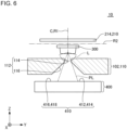
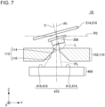
- Figs. 6 and 7 are each a view for describing an example of an operation of the optical device 10 according to an embodiment.
- a white circle with a black dot indicating the first direction X shows that a direction from a back side toward a front side of a paper surface is the positive direction in the first direction X and a direction from the front side toward the back side of the paper surface is the negative direction in the first direction X.
- only the reflection body 214 out of the movable support table 212 and the reflection body 214 of the movable reflection body 210 is shown for the sake of description.
- the first reference line R1 passes through the center of the swing of the movable reflection body 210 around the pair of first torsion bars 230 in parallel with the third direction Z, as viewed from the positive direction in the first direction X.
- the second reference line R2 passes through the center of the swing of the movable reflection body 210 around the pair of first torsion bars 230 in parallel with the second direction Y, as viewed from the positive direction in the first direction X.
- the center line C passes through the center of the movable reflection body 210 in the direction perpendicular to a surface of the reflection body 214 on the positive direction side in the third direction Z, as viewed from the positive direction in the first direction X.
- the first reference line R1 passes through the center of the aperture 112 in the first direction X and the second direction Y and the center of the light-receiving area 410 in the first direction X and the second direction Y.
- a light-emitting point at which light L is emitted from the first light-emitting element 300, as viewed from the positive direction in the first direction X, is shifted to a side where the first light-emitting element 300 is positioned along the center line C with respect to the center of a swing of the movable reflection body 210 around the pair of first torsion bars 230.
- a swing angle of the movable reflection body 210 around the pair of first torsion bars 230 is 0°, as viewed from the positive direction in the first direction X. Therefore, the center line C overlaps with the first reference line R1 in the first direction X, as viewed from the positive direction in the first direction X.
- the portion irradiated with the light L toward the narrow hole 114 passes through the narrow hole 114 in a direction parallel to the center line C as the passing light PL.
- the portion irradiated with the light L toward the periphery of the narrow hole 114 is shielded by a peripheral portion of the narrow hole 114 on a surface of the light-shielding body 110 on the positive direction side in the third direction Z.
- the passing light PL passes through the narrow hole 114 and then through the wide hole 116.
- the passing light PL spreads away from the light-emitting point of the first light-emitting element 300.
- the opening area of the wide hole 116 which is perpendicular to the third direction Z, is larger than the opening area of the narrow hole 114, which is perpendicular to the third direction Z. Therefore, the passing light PL can pass through the wide hole 116 without being shielded by the inner surface of the wide hole 116.
- the passing light PL passes through the wide hole 116, and then the center of the light-receiving area 410 in the first direction X and the second direction Y, and a periphery of the center are irradiated with the passing light PL.
- the movable reflection body 210 is in a state of rotating counterclockwise around the pair of first torsion bars 230 with respect to a state where a swing angle around the pair of first torsion bars 230 is 0°, as viewed from the positive direction in the first direction X.
- the center line C is in a state of rotating counterclockwise with respect to the first reference line R1, as viewed from the positive direction in the first direction X.
- the portion irradiated with the light L toward the narrow hole 114 passes through the narrow hole 114 in a direction inclined with respect to the first reference line R1, as the passing light PL.
- the passing light PL is inclined to a side opposite to the side on which the center line C is inclined with respect to the first reference line R1.
- the portion irradiated with the light L toward the periphery of the narrow hole 114 is shielded by a peripheral portion of the narrow hole 114 on a surface of the light-shielding body 110 on the positive direction side in the third direction Z.
- the passing light PL passes through the narrow hole 114 and then through the wide hole 116.
- the passing light PL spreads away from the light-emitting point of the first light-emitting element 300.
- the opening area of the wide hole 116 which is perpendicular to the third direction Z, is larger than the opening area of the narrow hole 114, which is perpendicular to the third direction Z. Therefore, the passing light PL can pass through the wide hole 116 without being shielded by the inner surface of the wide hole 116.
- the passing light PL passes through the wide hole 116, and then, a position shifted to the negative direction side in the second direction Y with respect to the center of the light-receiving area 410 in the first direction X and the second direction Y, and a periphery of the position are irradiated with the passing light PL.
- a spot generated in the light-receiving area 410 by the passing light PL moves to a side opposite to the side where the center line C is inclined with respect to the first reference line R1.
- a spot generated in the light-receiving area 410 by the passing light PL moves to a side opposite to the side where the center line C is inclined with respect to the first reference line R1 in the second direction Y.
- a spot generated in the light-receiving area 410 by the passing light PL moves to a side opposite to the side where the center line C is inclined with respect to the first reference line R1 in the first direction X.
- the swing of the movable reflection body 210 can be detected in accordance with a ratio of the intensity of a signal generated in each of the first light-receiving area 412, the second light-receiving area 414, the third light-receiving area 416, and the fourth light-receiving area 418 by the light L.
- the swing angle of the movable reflection body 210 around the pair of second torsion bars 250 is estimated by a first tilt error rate RX represented by Expression (1).
- the swing angle of the movable reflection body 210 around the pair of first torsion bars 230 is estimated by a second tilt error rate RY represented by Expression (2).
- the first tilt error amount EX is a tilt error amount of the swing of the movable reflection body 210 around the pair of second torsion bars 250.
- the second tilt error amount EY is a tilt error amount of the swing of the movable reflection body 210 around the pair of first torsion bars 230.
- A, B, C, and D are each an intensity of a signal generated in each of the first light-receiving area 412, the second light-receiving area 414, the third light-receiving area 416, and the fourth light-receiving area 418 by the passing light PL.
- the intensities A, B, C, and D are increased as the spot of light with which each of the first light-receiving area 412, the second light-receiving area 414, the third light-receiving area 416, and the fourth light-receiving area 418 is irradiated is larger.
- a group of the first light-receiving area 412 and the fourth light-receiving area 418, and a group of the second light-receiving area 414 and the third light-receiving area 416 are segmented in a moving direction of a spot generated in the light-receiving area 410 by the passing light PL in a case where the movable reflection body 210 swings around the pair of second torsion bars 250.
- the spot By allowing the spot to move in the first direction X, a relationship between the irradiation areas of the spots in the first light-receiving area 412 and the fourth light-receiving area 418 and the irradiation areas of the spots in the second light-receiving area 414 and the third light-receiving area 416 varies. Therefore, the first tilt error rate RX varies depending on the position of the spot in the first direction X in the light-receiving area 410. Therefore, the swing angle of the movable reflection body 210 around the pair of second torsion bars 250 can be estimated from the first tilt error rate RX.
- a group of the first light-receiving area 412 and the second light-receiving area 414, and a group of the third light-receiving area 416 and the fourth light-receiving area 418 are segmented in the moving direction of a spot generated in the light-receiving area 410 by the passing light PL in a case where the movable reflection body 210 swings around the pair of first torsion bars 230.
- the second tilt error rate RY varies depending on the position of the spot in the second direction Y in the light-receiving area 410. Therefore, the swing angle of the movable reflection body 210 around the pair of first torsion bars 230 can be estimated from the second tilt error rate RY.
- At least a portion of the light L passes through the aperture 112. Accordingly, the irradiation of the light-receiving area 410 with light different from the light L, such as external light, can be suppressed, as compared to a case where the light-shielding body 110 is not provided. Therefore, the swing of the movable reflection body 210 can be accurately detected, as compared with a case where the light-shielding body 110 is not provided.
- the portion irradiated with the light L toward the periphery of the narrow hole 114 is shielded by a peripheral portion of the narrow hole 114 on a surface of the light-shielding body 110 on the positive direction side in the third direction Z. Therefore, the spot generated in the light-receiving area 410 by the passing light PL can be reduced, as compared to a case where the light-shielding body 110 is not provided. Accordingly, the variation amount in the first tilt error rate RX and the variation amount in the second tilt error rate RY can be increased and the detection sensitivity for the swing of the movable reflection body 210 can be increased, as compared with a case where the light-shielding body 110 is not provided.
- the spot generated in the light-receiving area 410 by the passing light PL may be set to be smaller than the light-receiving area 410, as viewed from the positive direction in the third direction Z.
- the length in the first direction X of the spot generated in the light-receiving area 410 by the passing light PL may be, for example, more than 0.3 times and less than 0.7 times the length of the first direction X of the light-receiving area 410.
- an variation amount in the first tilt error amount EX can be increased and an SN ratio of the detection of the swing of the movable reflection body 210 around the pair of second torsion bars 250 can be increased, as compared with a case where the length of the spot is equal to or less than the lower limit of the numerical range.
- an variation amount in the first tilt error rate RX can be increased, and thus, the sensitivity of the detection of the swing of the movable reflection body 210 around the pair of second torsion bars 250 can be increased, as compared with a case where the length of the spot is more than the upper limit of the numerical range.
- the length in the second first direction Y of the spot generated in the light-receiving area 410 by the passing light PL may be, for example, more than 0.3 times and less than 0.7 times the length of the second direction Y of the light-receiving area 410.
- the amplitude in the first direction X of the spot generated in the light-receiving area 410 by the passing light PL may be, for example, more than 0.05 times and less than 0.1 times the length of the first direction X of the light-receiving area 410.
- an variation amount in the first tilt error rate RX can be increased, and thus, the sensitivity of the detection of the swing of the movable reflection body 210 around the pair of second torsion bars 250 can be increased, as compared with a case where the amplitude of the spot is equal to or less than the lower limit of the numerical range.
- the amplitude of the spot is in the numerical range, at least a portion of the spot can be suppressed from being irradiated the outside in the first direction X of the light-receiving area 410, as compared with a case where the amplitude of the spot is equal to or more than the upper limit of the numerical range.
- the amplitude of the spot generated in the light-receiving area 410 by the passing light PL in the second direction Y may also be, for example, more than 0.05 times and less than 0.1 times the length of the second direction Y of the light-receiving area 410.
- the size and the amplitude of the spot generated in the light-receiving area 410 by the passing light PL can be changed by appropriately adjusting conditions such as an opening area of the narrow hole 114 perpendicular to the third direction Z, a distance between a light-emitting point of the first light-emitting element 300 and an end of the narrow hole 114 on the positive direction side in the third direction Z, a distance between a light-emitting point of the first light-emitting element 300 and the light-receiving area 410 of the first light-receiving element 400, and a distance between a light-emitting point of the first light-emitting element 300 and the center of the swing of the movable reflection body 210.
- the entire light L may pass through the aperture 112. Even in this case, in a case where the opening area of the aperture 112 perpendicular to the third direction Z is appropriately set, the light-receiving area 410 can be suppressed from being irradiated with light different from the light L, as compared with a case where the light-shielding body 110 is not provided.
- an opening area of at least a portion of the aperture 112 on the side where the first light-receiving element 400 is positioned is larger than an opening area of at least a portion of the aperture 112 on the side where the first light-emitting element 300 is positioned.
- the opening area of the wide hole 116, which is perpendicular to the third direction Z, is larger than the opening area of the narrow hole 114, which is perpendicular to the third direction Z.
- the irradiation area of the passing light PL of the light-receiving area 410 can be increased, as compared to a case where the opening area of the wide hole 116, which is perpendicular to the third direction Z, is equal to or less than the opening area of the narrow hole 114, which is perpendicular to the third direction Z.
- the strength of the light-shielding body 110 can be increased, as compared with a case where the peripheral portion of the wide hole 116 of the light-shielding body 110 is not present.
- the inner surface of the wide hole 116 is a surface inclined with respect to the third direction Z.
- the inner surface of the wide hole 116 may be substantially parallel to the third direction Z.
- the irradiation area of the passing light PL of the light-receiving area 410 can be increased, as compared to a case where the opening area of the wide hole 116, which is perpendicular to the third direction Z, is equal to or less than the opening area of the narrow hole 114, which is perpendicular to the third direction Z.
- the strength of the light-shielding body 110 can be increased, as compared with a case where the peripheral portion of the wide hole 116 of the light-shielding body 110 is not present.
- Fig. 8 is a view showing a configuration of a sensor device 20 according to Examples.
- the sensor device 20 includes an optical device 10 according to the embodiment.
- the sensor device 20 further includes a second light-emitting element 12, a second light-receiving element 14, and a beam splitter 16.
- the sensor device 20 is a light detection and ranging (LiDAR).
- the second light-emitting element 12 is, for example, a laser diode (LD). As indicated by a solid-line arrow extending from the second light-emitting element 12 through the beam splitter 16 and the movable reflection body 210, light emitted from the second light-emitting element 12 passes through the beam splitter 16 and is reflected by the movable reflection body 210. The light reflected by the movable reflection body 210 is reflected or scattered by an object, which is not shown in the drawing, present outside the optical device 10.
- LD laser diode
- the second light-receiving element 14 is, for example, an avalanche photodiode (APD). As indicated by a solid-line arrow extending to the second light-receiving element 14 through the optical device 10 and the beam splitter 16, the second light-receiving element 14 is emitted from the second light-emitting element 12 and reflected by the movable reflection body 210, and thus, the reflected or scattered light is received by an object, which is not shown in the drawing, present outside the optical device 10. In Examples, the light received by the second light-receiving element 14 is reflected or scattered by the object, is reflected by the movable reflection body 210 and the beam splitter 16 to reach the second light-receiving element 14.
- APD avalanche photodiode
- the structure of the sensor device 20 is not limited to the structure according to Examples.
- the optical axis of the light, which is reflected by the movable reflection body 210 and with which the object present outside the optical device 10 is irradiated matches the optical axis of the light reflected or scattered by the object.
- the optical axis of the light which is reflected by the movable reflection body 210 and with which the object present outside the optical device 10 and the optical axis of the light reflected or scattered by the object is irradiated may be shifted from each other. In this case, the light reflected or scattered by the object reaches the second light-receiving element 14 without being reflected at the movable reflection body 210.
- the swing angle around the pair of first torsion bars 230 of the movable reflection body 210 in a state where the swing angle around the pair of first torsion bars 230 of the movable reflection body 210 is 0°, the center of the light-receiving area 410 in the first direction X and the second direction Y, and a periphery of the center are irradiated with the light L.
- a position shifted from the center of the light-receiving area 410 in the first direction X and the second direction Y, and a periphery of the position are irradiated with the light L.
- the swing angle around the pair of first torsion bars 230 of the movable reflection body 210 can be estimated with reference to the first tilt error rate RX and the second tilt error rate RY.
- the first light-receiving element 400 is a four-segment PD.
- the first light-receiving element 400 may be a two-segment PD.
- the light-receiving area 410 has two light-receiving areas segmented in the moving direction of the spot generated in the light-receiving area 410 by the light emitted from the first light-emitting element 300.
- the movable reflection body 210 rotates about only a single rotation axis
- measurement of the tilt error rate can be made easier by a configuration in which only two segmented light-receiving areas are provided rather than a configuration in which four segmented light-receiving areas are provided.
Landscapes
- Physics & Mathematics (AREA)
- General Physics & Mathematics (AREA)
- Engineering & Computer Science (AREA)
- Optics & Photonics (AREA)
- Computer Networks & Wireless Communication (AREA)
- Radar, Positioning & Navigation (AREA)
- Remote Sensing (AREA)
- Mechanical Light Control Or Optical Switches (AREA)
- Optical Transform (AREA)
- Mechanical Optical Scanning Systems (AREA)
- Optical Radar Systems And Details Thereof (AREA)
Abstract
Description
- The present invention relates to an optical device and a sensor device.
- In recent years, various optical devices such as light detection and ranging (LiDAR) have been developed. The optical device may have a micro-electro mechanical system (MEMS) mirror that reflects light emitted from a light-emitting element such as a laser diode (LD) . For example, as described in Patent Document 1, the MEMS mirror may be provided with a piezo-resistance element that detects a swing of the MEMS mirror.
- [Patent Document 1]
Japanese Unexamined Patent Publication No. 2014-56211 - The present inventors have studied to attach a light-emitting element to a movable reflection body instead of a piezo-resistance element or in addition to the piezo-resistance element in order to detect a swing of a movable reflection body such as a MEMS mirror. In this optical device, the swing of the movable reflection body is detected by allowing a light-receiving element such as a four-segment photodiode (PD) to receive light emitted from a light-emitting element. However, in this optical device, the light-receiving element may be irradiated with light different from the light emitted from the light-emitting element, such as external light. Therefore, there is room for improvement in the accuracy of detection of the swing of the movable reflection body.
- One example of problems to be solved by the present invention may be to accurately detect a swing of a movable reflection body.
- The invention as described in Claim 1 is an optical device including:
- a movable reflection body,
- a first light-emitting element attached to the movable reflection body,
- an aperture through which at least a portion of light emitted from the first light-emitting element passes, and
- a first light-receiving element that receives the light having passed through the aperture.
- The invention as described in Claim 6 is a sensor device including:
- the optical device,
- a second light-emitting element,
- a second light-receiving element that receives light emitted from the second light-emitting element, reflected by the movable reflection body, and reflected or scattered by an object present outside the optical device.
-
-
Fig. 1 is a perspective view of an optical device according to an embodiment. -
Fig. 2 is an exploded perspective view of the optical device according to the embodiment. -
Fig. 3 is a cross-sectional view taken along line A-A ofFig. 1 . -
Fig. 4 is a cross-sectional view taken along line B-B ofFig. 1 . -
Fig. 5 is a cross-sectional view taken along line C-C inFig. 1 . -
Fig. 6 is a view for describing an example of an operation of the optical device according to the embodiment. -
Fig. 7 is a view for describing an example of the operation of the optical device according to the embodiment. -
Fig. 8 is a view showing a configuration of a sensor device according to Examples. - Hereinafter, embodiments and Examples of the present invention will be described with reference to the drawings. In all drawings, the same constituent components are denoted by the same reference signs, and detailed explanation thereof will not be repeated.
-
Fig. 1 is a perspective view of anoptical device 10 according to an embodiment.Fig. 2 is an exploded perspective view of theoptical device 10 according to the embodiment.Fig. 3 is a cross-sectional view taken along line A-A ofFig. 1 .Fig. 4 is a cross-sectional view taken along line B-B ofFig. 1 .Fig. 5 is a cross-sectional view taken along line C-C inFig. 1 . - In
Figs. 1 to 5 , an arrow indicating a first direction X, a second direction Y, or a third direction Z indicates that a direction from a proximal end toward a distal end of the arrow is a positive direction in the direction indicated by the arrow, and that a direction from the distal end toward the proximal end of the arrow is a negative direction in the direction indicated by the arrow. InFig. 5 , an X-marked circle indicating the third direction Z indicates that a direction from the foreground to the background of a paper plane is a positive direction in the third direction Z and that a direction from the background to the foreground of the paper plane is a negative direction in the third direction Z. The first direction X, the second direction Y, and the third direction Z are orthogonal to each other. - As shown in
Figs. 1 to 4 , theoptical device 10 includes ahousing body 100, anoptical scanning device 200, a first light-emitting element 300, a first light-receiving element 400, aflexible substrate 500, a firstmagnetic circuit 610, a secondmagnetic circuit 620, and aheat sink 630. As shown inFigs. 1 to 4 , thehousing body 100 has abase 102 and alid 104. As shown inFigs. 1 to 5 , theoptical scanning device 200 includes amovable reflection body 210, afirst frame body 220, a pair of first torsion bars 230, asecond frame body 240, a pair of second torsion bars 250, afirst terminal 262, and asecond terminal 264. The pair of first torsion bars 230 include a first metal bar 232 and a second metal bar 234. The pair of second torsion bars 250 includes a third metal bar 252 and a fourth metal bar 254. - In
Figs. 1 to 5 , the positive direction in the first direction X is a direction from a side where the second metal bar 234 is positioned toward a side where the first metal bar 232 is positioned. The negative direction in the first direction X is a direction from the side where the first metal bar 232 is positioned toward the side where the second metal bar 234 is positioned. The positive direction in the second direction Y is a direction from a side where the fourth metal bar 254 is positioned toward a side where the third metal bar 252 is positioned. The negative direction in the second direction Y is a direction from the side where the third metal bar 252 is positioned toward the side where the fourth metal bar 254 is positioned. The positive direction in the third direction Z is a direction from a side where thebase 102 is positioned toward a side where thelid 104 is positioned. The negative direction in the third direction Z is a direction from the side where thelid 104 is positioned toward the side where thebase 102 is positioned. - The
housing body 100 houses theoptical scanning device 200, the first light-emitting element 300, the first light-receivingelement 400, at least a portion of theflexible substrate 500, the firstmagnetic circuit 610, the secondmagnetic circuit 620, and theheat sink 630. Thelid 104 is attached onto a surface of thebase 102 on the positive direction side in the third direction Z. - As shown in
Figs. 1 ,3 , and4 , in theoptical scanning device 200, at least a portion of themovable reflection body 210, at least a portion of thefirst frame body 220, and at least a portion of the pair of first torsion bars 230 are mounted on a surface side of thebase 102 in the positive direction in the third direction Z in a state of being exposed from theopening 150 of thelid 104. In addition, at least a portion of thesecond frame body 240 and at least a portion of the pair of second torsion bars 250 are covered with thelid 104, as viewed from the positive direction in the third direction Z. Therefore, it is possible to make it difficult for the first light-receivingelement 400 to be irradiated with external light, as compared with a case where at least a portion of thesecond frame body 240 and at least a portion of the pair of second torsion bars 250 are exposed from thelid 104, as viewed from the third direction Z. In addition, the reflected light from the second torsion bar 250 can be suppressed from returning to the light-receiving element for distance measurement, provided outside theoptical scanning device 200, even in a case where a metal portion with a relatively high reflectance of the second torsion bar 250 is irradiated with diffusely reflected light from the outside of theoptical scanning device 200 inside thehousing body 100, as compared with a case where at least a portion of the pair of second torsion bars 250 is exposed from thelid 104. - As shown in
Figs. 3 and4 , themovable reflection body 210 has a movable support table 212 and areflection body 214. As shown inFig. 5 , the movable support table 212 includes afirst metal body 212a, asecond metal body 212b, and aresin part 212c. At least a portion of thefirst metal body 212a is positioned on the positive direction side in the first direction X with respect to at least a portion of thesecond metal body 212b. At least a portion of thesecond metal body 212b is positioned on the negative direction side in the first direction X with respect to at least a portion of thefirst metal body 212a. Theresin part 212c covers at least a portion of a surface of thefirst metal body 212a on the positive direction side in the third direction Z and at least a portion of a surface of thesecond metal body 212b on the positive direction side in the third direction Z. Thereflection body 214 is positioned on a surface side of theresin part 212c in the positive direction in the third direction Z. The surface of thereflection body 214 on the positive direction side in the third direction Z is a reflection surface that reflects light from the outside of theoptical scanning device 200, such as distance measurement light. Thereflection body 214 is swingable together with the movable support table 212. - As shown in
Fig. 5 , thefirst frame body 220 includes a firstmetal frame body 222 and afirst resin body 224. The firstmetal frame body 222 is positioned in at least a portion of a region surrounding themovable reflection body 210 and the pair of first torsion bars 230, as viewed from the third direction Z. At least a portion of the firstmetal frame body 222 is sealed by thefirst resin body 224. In a case where thefirst resin body 224 is provided, an unnecessary vibration of thefirst frame body 220 can be suppressed, as compared to a case where thefirst resin body 224 is not provided. - The first metal bar 232 connects the
movable reflection body 210 and thefirst frame body 220. In addition, the first metal bar 232 extends parallel to the first direction X. Specifically, as shown inFig. 5 , an end of the first metal bar 232 on the negative direction side in the first direction X is connected to thefirst metal body 212a. An end of the first metal bar 232 on the positive direction side in the first direction X is connected to an inner edge of the end of the firstmetal frame body 222 on the positive direction side in the first direction X. - The second metal bar 234 connects the
movable reflection body 210 and thefirst frame body 220. In addition, the second metal bar 234 extends parallel to the first direction X. Specifically, as shown inFig. 5 , an end of the second metal bar 234 on the positive direction side in the first direction X is connected to thesecond metal body 212b. An end of the second metal bar 234 on the negative direction side in the first direction X is connected to an inner edge of the end of the firstmetal frame body 222 on the negative direction side in the first direction X. - As shown in
Figs. 2 ,3 , and4 , a firstpermanent magnet 216 is provided on a surface side of themovable reflection body 210 in the negative direction in the third direction Z. In the examples shown inFigs. 2 ,3 , and4 , the firstpermanent magnet 216 is positioned on the negative direction side in the first direction X with respect to the center of themovable reflection body 210 in the first direction X. Themovable reflection body 210 swings with respect to thefirst frame body 220 using the pair of first torsion bars 230 as a rotation axis by allowing the firstpermanent magnet 216 to receive a magnetic flux generated from the firstmagnetic circuit 610. - Specifically, as shown in
Figs. 2 ,3 , and4 , the firstmagnetic circuit 610 includes afirst coil 612, afirst yoke 614, and a pair ofsecond yokes 616. Thefirst coil 612 is wound around thefirst yoke 614. As shown inFigs. 3 and4 , thefirst yoke 614 extends parallel to the second direction Y in the space on the negative direction side in the third direction Z with respect to the first light-emittingelement 300 and theflexible substrate 500. Each of the pair ofsecond yokes 616 is connected to each of an end of thefirst yoke 614 on the positive direction side in the second direction Y and an end of thefirst yoke 614 on the negative direction side in the second direction Y. As shown inFig. 4 , each tip of the pair ofsecond yokes 616 faces each other through a space positioned on the negative direction side in the third direction Z with respect to themovable reflection body 210. By allowing an alternating current to flow through thefirst coil 612, an alternating current magnetic field is generated from each tip of the pair ofsecond yokes 616. Themovable reflection body 210 swings with respect to thefirst frame body 220 using the pair of first torsion bars 230 as a rotation axis by allowing the firstpermanent magnet 216 to receive the alternating current magnetic field. - As shown in
Fig. 5 , thesecond frame body 240 includes a secondmetal frame body 242 and asecond resin body 244. The secondmetal frame body 242 is positioned in at least a portion of a region surrounding thefirst frame body 220 and the pair of second torsion bars 250, as viewed from the third direction Z. At least a portion of the secondmetal frame body 242 is sealed by thesecond resin body 244. In a case where thesecond resin body 244 is provided, an unnecessary vibration of thesecond frame body 240 can be suppressed, as compared to a case where thesecond resin body 244 is not provided. - The third metal bar 252 connects the
first frame body 220 and thesecond frame body 240. In addition, the third metal bar 252 extends parallel to the second direction Y. Specifically, as shown inFig. 5 , an end of the third metal bar 252 on the negative direction side in the second direction Y is connected to the part of the outer edge of the firstmetal frame body 222 that corresponds to the positive side of the second direction Y and the center of the first direction X. An end of the third metal bar 252 on the positive direction side in the second direction Y is connected to the part of the inner edge of the secondmetal frame body 242 that corresponds to the positive side of the second direction Y and the center of the first direction X. - The fourth metal bar 254 connects the
first frame body 220 and thesecond frame body 240. In addition, the fourth metal bar 254 extends parallel to the second direction Y. Specifically, as shown inFig. 5 , an end of the fourth metal bar 254 on the positive direction side in the second direction Y connected to the part of the outer edge of the firstmetal frame body 222 that corresponds to the negative side of the second direction Y and the center of the first direction X. An end of the fourth metal bar 254 on the negative direction side in the second direction Y is connected to the part of the inner edge of the secondmetal frame body 242 that corresponds to the negative side of the second direction Y and the center of the first direction X. - As shown in
Figs. 2 and3 , each of the pair of secondpermanent magnets 226 is provided at each of both ends of thefirst frame body 220 in the first direction X. In the examples shown inFigs. 2 and3 , each of the secondpermanent magnets 226 is provided on a surface side of thefirst frame body 220 in the negative direction in the third direction Z. Thefirst frame body 220 swings with respect to thesecond frame body 240 using the pair of second torsion bars 250 as a rotation axis by allowing each of the pair of secondpermanent magnets 226 to receive a magnetic flux generated from the secondmagnetic circuit 620. Thus, themovable reflection body 210 is integrated with thefirst frame body 220 and the pair of first torsion bars 230 to swing with respect to thesecond frame body 240 using the second torsion bar 250 as a rotation axis. - Specifically, as shown in
Fig. 2 , the secondmagnetic circuit 620 includes one pair ofsecond coils 622 positioned on the positive direction side in the first direction X and the other pair ofsecond coils 622 positioned on the negative direction side in the first direction X. The pair ofsecond coils 622 positioned on the positive direction side in the first direction X face each other through the end part of thefirst frame body 220 on the positive direction side in the first direction X. By allowing an alternating current to flow through the pair ofsecond coils 622, an alternating current magnetic field is generated from the pair ofsecond coils 622. In addition, the other pair ofsecond coils 622 positioned on the negative direction side in the first direction X face each other through the end part of themovable reflection body 210 on the negative direction side in the first direction X. By allowing an alternating current to flow through the pair ofsecond coils 622, an alternating current magnetic field is generated from the other pair ofsecond coils 622. Thefirst frame body 220 swings with respect to thesecond frame body 240 using the pair ofsecond frame bodies 240 as a rotation axis by allowing the secondpermanent magnet 226 provided at each of both ends of thefirst frame body 220 in the first direction X to receive the alternating magnetic field. Thus, themovable reflection body 210 is integrated with thefirst frame body 220 and the pair of first torsion bars 230 to swing with respect to thesecond frame body 240 using the second torsion bar 250 as a rotation axis. - In an embodiment, at least a portion of each of the four
second coils 622 is covered with thelid 104, as viewed from the positive direction in the third direction Z. Accordingly, the reflected light from thesecond coil 622 can be suppressed from returning to the light-receiving element for distance measurement, provided outside theoptical scanning device 200, even in a case where a metal portion with a relatively high reflectance of thesecond coil 622 is irradiated with diffusely reflected light from the outside of theoptical scanning device 200 inside thehousing body 100, as compared with a case where at least a portion of eachsecond coil 622 is exposed from thelid 104. In addition, thelid 104 covers a metal portion with a relatively high reflectance, such as a wiring that connects theflexible substrate 500 and thefirst coil 612, a soldering portion between the wiring and theflexible substrate 500, a wiring that connects theflexible substrate 500 and thesecond coil 622, and a soldering portion between the wiring and theflexible substrate 500, as viewed from the positive direction in the third direction Z. Accordingly, the reflected light from the metal portion can be suppressed from returning to the light-receiving element for distance measurement, provided outside theoptical scanning device 200, even in a case where the metal portion is irradiated with the diffusely reflected light, as compared with a case where the metal portion is not covered with thelid 104. - Furthermore, heat generated from the second
magnetic circuit 620 is transferred to theheat sink 630 through a heat transfer agent which is not shown in the drawing. Thus, the heat generated from the secondmagnetic circuit 620 can be released to the outside of theoptical device 10. - The
first terminal 262 and thesecond terminal 264 are connected to the secondmetal frame body 242. Specifically, as shown inFig. 5 , thefirst terminal 262 is connected to the part of the outer edge of the secondmetal frame body 242 that corresponds to the positive side of the second direction Y and the center of the first direction X. Thesecond terminal 264 is connected to the part of the outer edge of the secondmetal frame body 242 that corresponds to the positive side of the second direction Y and the part shifted to the positive direction side in the second direction Y from center of the first direction X. It should be noted that a position where thefirst terminal 262 and thesecond terminal 264 are provided is not limited to this example. In an embodiment, thefirst terminal 262 and thesecond terminal 264 are pressed against theflexible substrate 500 by thelid 104. Accordingly, it is easier to ensure continuity between thefirst terminal 262 and theflexible substrate 500, and a conduction between thesecond terminal 264 and theflexible substrate 500, as compared with a case where thefirst terminal 262 and thesecond terminal 264 are not pressed against theflexible substrate 500 by thelid 104. - The first light-emitting
element 300 is, for example, a light-emitting diode (LED). The first light-emittingelement 300 is attached onto the negative direction side in the third direction Z of the movable support table 212. Accordingly, the first light-emittingelement 300 is swingable together with themovable reflection body 210. - One of the anode and the cathode of the first light-emitting
element 300 is electrically connected to thefirst metal body 212a. The other of the anode and the cathode of the first light-emittingelement 300 is electrically connected to thesecond metal body 212b. In an embodiment, the drive current of the first light-emittingelement 300 can flow between thefirst terminal 262 and thesecond terminal 264. - Specifically, as shown in
Fig. 5 , the firstmetal frame body 222 is provided with twofirst split parts 222a. One of the twofirst split parts 222a is provided between a connection part between the firstmetal frame body 222 and the first metal bar 232, and a connection part between the firstmetal frame body 222 and the fourth metal bar 254. The other of the twofirst split parts 222a is provided between a connection part between the firstmetal frame body 222 and the second metal bar 234, and a connection part between the firstmetal frame body 222 and the third metal bar 252. Thus, an occurrence of a short circuit between thefirst metal body 212a and thesecond metal body 212b through the firstmetal frame body 222 is prevented. In addition, an occurrence of a short circuit between the third metal bar 252 and the fourth metal bar 254 through the firstmetal frame body 222 is prevented. - In addition, as shown in
Fig. 5 , the secondmetal frame body 242 includes asecond split part 242a on the positive direction side in the second direction Y of the secondmetal frame body 242, and anothersecond split part 242a on the negative direction side in the second direction Y of the secondmetal frame body 242. Thesecond split part 242a on the positive direction side in the second direction Y of the secondmetal frame body 242 is provided in a portion of the secondmetal frame body 242 which is corresponds to the positive side of the second direction Y and the part shifted to the negative direction side in the first direction X from the center part in the first direction X. In the example shown inFig. 5 , thesecond split part 242a on the positive direction side in the second direction Y of the secondmetal frame body 242 is positioned between a connection part between the secondmetal frame body 242 and thefirst terminal 262, and a connection part between the secondmetal frame body 242 and thesecond terminal 264. The othersecond split part 242a on the negative direction side in the second direction Y of the secondmetal frame body 242 is provided in a portion of the secondmetal frame body 242 which is corresponds to the negative side of the second direction Y and the part shifted to the positive direction side in the first direction X from the center part in the first direction X. These twosecond split parts 242a prevent an occurrence of a short circuit between thefirst terminal 262 and thesecond terminal 264 through the secondmetal frame body 242. - In an embodiment, the drive current of the first light-emitting
element 300 can flow from thefirst terminal 262 to thesecond terminal 264, through the third metal bar 252, a portion between a connection part between the firstmetal frame body 222 and the third metal bar 252, and a connection part between the firstmetal frame body 222 and the first metal bar 232 in the firstmetal frame body 222; a portion between a connection part between the firstmetal frame body 222 and the second metal bar 234, and a connection part between the firstmetal frame body 222 and the fourth metal bar 254 in the first metal bar 232, thefirst metal body 212a, the first light-emittingelement 300, thesecond metal body 212b, the second metal bar 234, and the firstmetal frame body 222; and a portion between a connection part between the secondmetal frame body 242 and the fourth metal bar 254, and a connection part between the secondmetal frame body 242 and thesecond terminal 264 in the fourth metal bar 254 and the fourthmetal frame body 242. In this example, the drive current flows from thefirst terminal 262 to thesecond terminal 264. However, the drive current may flow from thesecond terminal 264 to thefirst terminal 262. - As shown in
Figs. 3 and4 , the first light-receivingelement 400 is positioned on the negative direction side in the third direction Z with respect to the first light-emittingelement 300. At least a portion of the light-shieldingbody 110 of thebase 102 is positioned between the first light-emittingelement 300 and the first light-receivingelement 400 in the third direction Z. The light-shieldingbody 110 defines anaperture 112. At least a portion of light emitted from the first light-emittingelement 300 passes through theaperture 112. The first light-receivingelement 400 receives light having passed through theaperture 112. - In the examples shown in
Figs. 3 and4 , theaperture 112 includes anarrow hole 114 and awide hole 116. Thenarrow hole 114 penetrates a surface of the light-shieldingbody 110 on the positive direction side in the third direction Z. The inner surface of thenarrow hole 114 is substantially parallel to the third direction Z. Thus, the opening area of thenarrow hole 114, which is perpendicular to the third direction Z, is constant regardless of the position in the third direction Z. Thewide hole 116 penetrates a surface of the light-shieldingbody 110 on the negative direction side in the third direction Z. An end of thewide hole 116 on the positive direction side in the third direction Z communicates with an end of thenarrow hole 114 on the negative direction side in the third direction Z. The opening area of thewide hole 116, which is perpendicular to the third direction Z, is larger than the opening area of thenarrow hole 114, which is perpendicular to the third direction Z. Specifically, in the examples shown inFigs. 3 and4 , the inner surface of thewide hole 116 is a surface inclined with respect to the third direction Z. Thus, the opening area of thewide hole 116, which is perpendicular to the third direction Z, increases from the positive direction to the negative direction in the third direction Z. It should be noted that the shape of theaperture 112 is not limited to the examples shown inFigs. 3 and4 . For example, the inner surface of thewide hole 116 may be substantially parallel to the third direction Z. In this case, the opening area of thewide hole 116, which is perpendicular to the third direction Z, is constant regardless of the position in the third direction Z. - The first light-receiving
element 400 is, for example, a four-segment PD (photodiode). As shown inFigs. 2 ,3 , and4 , a surface of the first light-receivingelement 400 on the positive direction side in the third direction Z has a light-receivingarea 410. The light-receivingarea 410 includes a first light-receivingarea 412, a second light-receivingarea 414, a third light-receivingarea 416, and a fourth light-receivingarea 418. The first light-receivingarea 412, the second light-receivingarea 414, the third light-receivingarea 416, and the fourth light-receivingarea 418 are segmented from each other. Specifically, the first light-receivingarea 412 is positioned on the positive direction side in the first direction X and on the positive direction side in the second direction Y with respect to the center of the light-receivingarea 410 in the first direction X and the second direction Y. The second light-receivingarea 414 is positioned on the negative direction side in the first direction X and on the positive direction side in the second direction Y with respect to the center of the light-receivingarea 410 in the first direction X and the second direction Y. The third light-receivingarea 416 is positioned on the negative direction side in the first direction X and on the negative direction side in the second direction Y with respect to the center of the light-receivingarea 410 in the first direction X and the second direction Y. The fourth light-receivingarea 418 is positioned on the positive direction side in the first direction X and the negative direction side in the second direction Y with respect to the center of the light-receivingarea 410 in the first direction X and the second direction Y. - The
flexible substrate 500 is, for example, a flexible printed circuit (FPC). Theflexible substrate 500 is electrically connected to the first light-receivingelement 400. Theflexible substrate 500 is provided to transmit a signal generated in the first light-receivingelement 400 by allowing the first light-receivingelement 400 to receive light. Theflexible substrate 500 is pulled out from thehousing body 100 toward the negative direction side in the second direction Y. -
Figs. 6 and7 are each a view for describing an example of an operation of theoptical device 10 according to an embodiment. InFigs. 6 and7 , a white circle with a black dot indicating the first direction X shows that a direction from a back side toward a front side of a paper surface is the positive direction in the first direction X and a direction from the front side toward the back side of the paper surface is the negative direction in the first direction X. In addition, inFigs. 6 and7 , only thereflection body 214 out of the movable support table 212 and thereflection body 214 of themovable reflection body 210 is shown for the sake of description. - In
Figs. 6 and7 , the first reference line R1, the second reference line R2, and the center line C are virtually shown for the sake of description. The first reference line R1 passes through the center of the swing of themovable reflection body 210 around the pair of first torsion bars 230 in parallel with the third direction Z, as viewed from the positive direction in the first direction X. The second reference line R2 passes through the center of the swing of themovable reflection body 210 around the pair of first torsion bars 230 in parallel with the second direction Y, as viewed from the positive direction in the first direction X. The center line C passes through the center of themovable reflection body 210 in the direction perpendicular to a surface of thereflection body 214 on the positive direction side in the third direction Z, as viewed from the positive direction in the first direction X. - In the examples shown in
Figs. 6 and7 , the first reference line R1 passes through the center of theaperture 112 in the first direction X and the second direction Y and the center of the light-receivingarea 410 in the first direction X and the second direction Y. In addition, in the examples shown inFigs. 6 and7 , a light-emitting point at which light L is emitted from the first light-emittingelement 300, as viewed from the positive direction in the first direction X, is shifted to a side where the first light-emittingelement 300 is positioned along the center line C with respect to the center of a swing of themovable reflection body 210 around the pair of first torsion bars 230. - The state shown in
Fig. 6 will be described. In the state shown inFig. 6 , a swing angle of themovable reflection body 210 around the pair of first torsion bars 230 is 0°, as viewed from the positive direction in the first direction X. Therefore, the center line C overlaps with the first reference line R1 in the first direction X, as viewed from the positive direction in the first direction X. - The light L spreads toward the periphery of a center line C as a distance from the light-emitting point of the first light-emitting
element 300 is increased. The portion irradiated with the light L toward thenarrow hole 114 passes through thenarrow hole 114 in a direction parallel to the center line C as the passing light PL. On the contrary, the portion irradiated with the light L toward the periphery of thenarrow hole 114 is shielded by a peripheral portion of thenarrow hole 114 on a surface of the light-shieldingbody 110 on the positive direction side in the third direction Z. - The passing light PL passes through the
narrow hole 114 and then through thewide hole 116. The passing light PL spreads away from the light-emitting point of the first light-emittingelement 300. On the other hand, the opening area of thewide hole 116, which is perpendicular to the third direction Z, is larger than the opening area of thenarrow hole 114, which is perpendicular to the third direction Z. Therefore, the passing light PL can pass through thewide hole 116 without being shielded by the inner surface of thewide hole 116. The passing light PL passes through thewide hole 116, and then the center of the light-receivingarea 410 in the first direction X and the second direction Y, and a periphery of the center are irradiated with the passing light PL. - The state shown in
Fig. 7 will be described. In the state shown inFig. 7 , themovable reflection body 210 is in a state of rotating counterclockwise around the pair of first torsion bars 230 with respect to a state where a swing angle around the pair of first torsion bars 230 is 0°, as viewed from the positive direction in the first direction X. Thus, the center line C is in a state of rotating counterclockwise with respect to the first reference line R1, as viewed from the positive direction in the first direction X. - The light L spreads toward the periphery of a center line C as a distance from the light-emitting point of the first light-emitting
element 300 is increased. The portion irradiated with the light L toward thenarrow hole 114 passes through thenarrow hole 114 in a direction inclined with respect to the first reference line R1, as the passing light PL. Specifically, the passing light PL is inclined to a side opposite to the side on which the center line C is inclined with respect to the first reference line R1. On the contrary, the portion irradiated with the light L toward the periphery of thenarrow hole 114 is shielded by a peripheral portion of thenarrow hole 114 on a surface of the light-shieldingbody 110 on the positive direction side in the third direction Z. - The passing light PL passes through the
narrow hole 114 and then through thewide hole 116. The passing light PL spreads away from the light-emitting point of the first light-emittingelement 300. On the other hand, the opening area of thewide hole 116, which is perpendicular to the third direction Z, is larger than the opening area of thenarrow hole 114, which is perpendicular to the third direction Z. Therefore, the passing light PL can pass through thewide hole 116 without being shielded by the inner surface of thewide hole 116. The passing light PL passes through thewide hole 116, and then, a position shifted to the negative direction side in the second direction Y with respect to the center of the light-receivingarea 410 in the first direction X and the second direction Y, and a periphery of the position are irradiated with the passing light PL. - From the examples shown in
Figs. 6 and7 , in a case where a part of the light L passes through theaperture 112, a spot generated in the light-receivingarea 410 by the passing light PL moves to a side opposite to the side where the center line C is inclined with respect to the first reference line R1. For example, as shown inFigs. 6 and7 , in a case where themovable reflection body 210 swings around the pair of first torsion bars 230, a spot generated in the light-receivingarea 410 by the passing light PL moves to a side opposite to the side where the center line C is inclined with respect to the first reference line R1 in the second direction Y. In addition, in a case where themovable reflection body 210 swings around the pair of second torsion bars 250, a spot generated in the light-receivingarea 410 by the passing light PL moves to a side opposite to the side where the center line C is inclined with respect to the first reference line R1 in the first direction X. - In an embodiment, the swing of the
movable reflection body 210 can be detected in accordance with a ratio of the intensity of a signal generated in each of the first light-receivingarea 412, the second light-receivingarea 414, the third light-receivingarea 416, and the fourth light-receivingarea 418 by the light L. Specifically, the swing angle of themovable reflection body 210 around the pair of second torsion bars 250 is estimated by a first tilt error rate RX represented by Expression (1). In addition, the swing angle of themovable reflection body 210 around the pair of first torsion bars 230 is estimated by a second tilt error rate RY represented by Expression (2).


- It should be noted that the first tilt error amount EX is a tilt error amount of the swing of the
movable reflection body 210 around the pair of second torsion bars 250. The second tilt error amount EY is a tilt error amount of the swing of themovable reflection body 210 around the pair of first torsion bars 230. A, B, C, and D are each an intensity of a signal generated in each of the first light-receivingarea 412, the second light-receivingarea 414, the third light-receivingarea 416, and the fourth light-receivingarea 418 by the passing light PL. The intensities A, B, C, and D are increased as the spot of light with which each of the first light-receivingarea 412, the second light-receivingarea 414, the third light-receivingarea 416, and the fourth light-receivingarea 418 is irradiated is larger. - A group of the first light-receiving
area 412 and the fourth light-receivingarea 418, and a group of the second light-receivingarea 414 and the third light-receivingarea 416 are segmented in a moving direction of a spot generated in the light-receivingarea 410 by the passing light PL in a case where themovable reflection body 210 swings around the pair of second torsion bars 250. By allowing the spot to move in the first direction X, a relationship between the irradiation areas of the spots in the first light-receivingarea 412 and the fourth light-receivingarea 418 and the irradiation areas of the spots in the second light-receivingarea 414 and the third light-receivingarea 416 varies. Therefore, the first tilt error rate RX varies depending on the position of the spot in the first direction X in the light-receivingarea 410. Therefore, the swing angle of themovable reflection body 210 around the pair of second torsion bars 250 can be estimated from the first tilt error rate RX. - A group of the first light-receiving
area 412 and the second light-receivingarea 414, and a group of the third light-receivingarea 416 and the fourth light-receivingarea 418 are segmented in the moving direction of a spot generated in the light-receivingarea 410 by the passing light PL in a case where themovable reflection body 210 swings around the pair of first torsion bars 230. By allowing the spot to move in the second direction Y, a relationship between the irradiation areas of the spots in the first light-receivingarea 412 and the second light-receivingarea 414 and the irradiation areas of the spots in the third light-receivingarea 416 and the fourth light-receivingarea 418 varies. Therefore, the second tilt error rate RY varies depending on the position of the spot in the second direction Y in the light-receivingarea 410. Therefore, the swing angle of themovable reflection body 210 around the pair of first torsion bars 230 can be estimated from the second tilt error rate RY. - In an embodiment, at least a portion of the light L passes through the
aperture 112. Accordingly, the irradiation of the light-receivingarea 410 with light different from the light L, such as external light, can be suppressed, as compared to a case where the light-shieldingbody 110 is not provided. Therefore, the swing of themovable reflection body 210 can be accurately detected, as compared with a case where the light-shieldingbody 110 is not provided. - In addition, in an embodiment, the portion irradiated with the light L toward the periphery of the
narrow hole 114 is shielded by a peripheral portion of thenarrow hole 114 on a surface of the light-shieldingbody 110 on the positive direction side in the third direction Z. Therefore, the spot generated in the light-receivingarea 410 by the passing light PL can be reduced, as compared to a case where the light-shieldingbody 110 is not provided. Accordingly, the variation amount in the first tilt error rate RX and the variation amount in the second tilt error rate RY can be increased and the detection sensitivity for the swing of themovable reflection body 210 can be increased, as compared with a case where the light-shieldingbody 110 is not provided. - In one example, the spot generated in the light-receiving
area 410 by the passing light PL may be set to be smaller than the light-receivingarea 410, as viewed from the positive direction in the third direction Z. Specifically, the length in the first direction X of the spot generated in the light-receivingarea 410 by the passing light PL may be, for example, more than 0.3 times and less than 0.7 times the length of the first direction X of the light-receivingarea 410. In a case where the length of the spot is in the numerical range, an variation amount in the first tilt error amount EX can be increased and an SN ratio of the detection of the swing of themovable reflection body 210 around the pair of second torsion bars 250 can be increased, as compared with a case where the length of the spot is equal to or less than the lower limit of the numerical range. In a case where the length of the spot is in the numerical range, an variation amount in the first tilt error rate RX can be increased, and thus, the sensitivity of the detection of the swing of themovable reflection body 210 around the pair of second torsion bars 250 can be increased, as compared with a case where the length of the spot is more than the upper limit of the numerical range. The length in the second first direction Y of the spot generated in the light-receivingarea 410 by the passing light PL may be, for example, more than 0.3 times and less than 0.7 times the length of the second direction Y of the light-receivingarea 410. - In addition, the amplitude in the first direction X of the spot generated in the light-receiving
area 410 by the passing light PL may be, for example, more than 0.05 times and less than 0.1 times the length of the first direction X of the light-receivingarea 410. In a case where the amplitude of the spot is in the numerical range, an variation amount in the first tilt error rate RX can be increased, and thus, the sensitivity of the detection of the swing of themovable reflection body 210 around the pair of second torsion bars 250 can be increased, as compared with a case where the amplitude of the spot is equal to or less than the lower limit of the numerical range. In a case where the amplitude of the spot is in the numerical range, at least a portion of the spot can be suppressed from being irradiated the outside in the first direction X of the light-receivingarea 410, as compared with a case where the amplitude of the spot is equal to or more than the upper limit of the numerical range. The amplitude of the spot generated in the light-receivingarea 410 by the passing light PL in the second direction Y may also be, for example, more than 0.05 times and less than 0.1 times the length of the second direction Y of the light-receivingarea 410. - The size and the amplitude of the spot generated in the light-receiving
area 410 by the passing light PL can be changed by appropriately adjusting conditions such as an opening area of thenarrow hole 114 perpendicular to the third direction Z, a distance between a light-emitting point of the first light-emittingelement 300 and an end of thenarrow hole 114 on the positive direction side in the third direction Z, a distance between a light-emitting point of the first light-emittingelement 300 and the light-receivingarea 410 of the first light-receivingelement 400, and a distance between a light-emitting point of the first light-emittingelement 300 and the center of the swing of themovable reflection body 210. - Furthermore, the entire light L may pass through the
aperture 112. Even in this case, in a case where the opening area of theaperture 112 perpendicular to the third direction Z is appropriately set, the light-receivingarea 410 can be suppressed from being irradiated with light different from the light L, as compared with a case where the light-shieldingbody 110 is not provided. - In addition, in an embodiment, an opening area of at least a portion of the
aperture 112 on the side where the first light-receivingelement 400 is positioned is larger than an opening area of at least a portion of theaperture 112 on the side where the first light-emittingelement 300 is positioned. Specifically, on the other hand, the opening area of thewide hole 116, which is perpendicular to the third direction Z, is larger than the opening area of thenarrow hole 114, which is perpendicular to the third direction Z. Accordingly, the irradiation area of the passing light PL of the light-receivingarea 410 can be increased, as compared to a case where the opening area of thewide hole 116, which is perpendicular to the third direction Z, is equal to or less than the opening area of thenarrow hole 114, which is perpendicular to the third direction Z. In addition, the strength of the light-shieldingbody 110 can be increased, as compared with a case where the peripheral portion of thewide hole 116 of the light-shieldingbody 110 is not present. - Furthermore, in the examples shown in
Figs. 6 and7 , the inner surface of thewide hole 116 is a surface inclined with respect to the third direction Z. However, the inner surface of thewide hole 116 may be substantially parallel to the third direction Z. Also in this example, the irradiation area of the passing light PL of the light-receivingarea 410 can be increased, as compared to a case where the opening area of thewide hole 116, which is perpendicular to the third direction Z, is equal to or less than the opening area of thenarrow hole 114, which is perpendicular to the third direction Z. In addition, the strength of the light-shieldingbody 110 can be increased, as compared with a case where the peripheral portion of thewide hole 116 of the light-shieldingbody 110 is not present. -
Fig. 8 is a view showing a configuration of asensor device 20 according to Examples. - The
sensor device 20 includes anoptical device 10 according to the embodiment. Thesensor device 20 further includes a second light-emittingelement 12, a second light-receivingelement 14, and abeam splitter 16. In Examples, thesensor device 20 is a light detection and ranging (LiDAR). - The second light-emitting
element 12 is, for example, a laser diode (LD). As indicated by a solid-line arrow extending from the second light-emittingelement 12 through thebeam splitter 16 and themovable reflection body 210, light emitted from the second light-emittingelement 12 passes through thebeam splitter 16 and is reflected by themovable reflection body 210. The light reflected by themovable reflection body 210 is reflected or scattered by an object, which is not shown in the drawing, present outside theoptical device 10. - The second light-receiving
element 14 is, for example, an avalanche photodiode (APD). As indicated by a solid-line arrow extending to the second light-receivingelement 14 through theoptical device 10 and thebeam splitter 16, the second light-receivingelement 14 is emitted from the second light-emittingelement 12 and reflected by themovable reflection body 210, and thus, the reflected or scattered light is received by an object, which is not shown in the drawing, present outside theoptical device 10. In Examples, the light received by the second light-receivingelement 14 is reflected or scattered by the object, is reflected by themovable reflection body 210 and thebeam splitter 16 to reach the second light-receivingelement 14. - The structure of the
sensor device 20 is not limited to the structure according to Examples. For example, in Examples, the optical axis of the light, which is reflected by themovable reflection body 210 and with which the object present outside theoptical device 10 is irradiated matches the optical axis of the light reflected or scattered by the object. However, the optical axis of the light which is reflected by themovable reflection body 210 and with which the object present outside theoptical device 10 and the optical axis of the light reflected or scattered by the object is irradiated may be shifted from each other. In this case, the light reflected or scattered by the object reaches the second light-receivingelement 14 without being reflected at themovable reflection body 210. - Hitherto, the embodiment and examples of the present invention have been described above with reference to the drawings, but these are examples of the present invention, and various configurations other than the above description can be adopted.
- For example, in an embodiment, as shown in
Fig. 6 , in a state where the swing angle around the pair of first torsion bars 230 of themovable reflection body 210 is 0°, the center of the light-receivingarea 410 in the first direction X and the second direction Y, and a periphery of the center are irradiated with the light L. However, in a state where the swing angle around the pair of first torsion bars 230 of themovable reflection body 210 is 0°, a position shifted from the center of the light-receivingarea 410 in the first direction X and the second direction Y, and a periphery of the position are irradiated with the light L. Even in this case, the swing angle around the pair of first torsion bars 230 of themovable reflection body 210 can be estimated with reference to the first tilt error rate RX and the second tilt error rate RY. - In addition, in an embodiment, the first light-receiving
element 400 is a four-segment PD. However, in a case where themovable reflection body 210 rotates around only a single rotation axis, the first light-receivingelement 400 may be a two-segment PD. In this example, the light-receivingarea 410 has two light-receiving areas segmented in the moving direction of the spot generated in the light-receivingarea 410 by the light emitted from the first light-emittingelement 300. In a case where themovable reflection body 210 rotates about only a single rotation axis, measurement of the tilt error rate can be made easier by a configuration in which only two segmented light-receiving areas are provided rather than a configuration in which four segmented light-receiving areas are provided. -
- 10 optical device
- 12 second light-emitting element
- 14 second light-receiving element
- 16 beam splitter
- 20 sensor device
- 100 housing body
- 102 base
- 104 lid
- 110 light-shielding body
- 112 aperture
- 114 narrow hole
- 116 wide hole
- 150 opening
- 200 optical scanning device
- 210 movable reflection body
- 212 movable support table
- 212a first metal body
- 212b second metal body
- 212c resin part
- 214 reflection body
- 216 first permanent magnet
- 220 first frame body
- 222 first metal frame body
- 222a first split part
- 224 first resin body
- 226 second permanent magnet
- 230 first torsion bar
- 232 first metal bar
- 234 second metal bar
- 240 second frame body
- 242 second metal frame body
- 242a second split part
- 244 second resin body
- 250 second torsion bar
- 252 third metal bar
- 254 fourth metal bar
- 262 first terminal
- 264 second terminal
- 300 first light-emitting element
- 400 first light-receiving element
- 410 light-receiving area
- 412 first light-receiving area
- 414 second light-receiving area
- 416 third light-receiving area
- 418 fourth light-receiving area
- 500 flexible substrate
- 610 first magnetic circuit
- 612 first coil
- 614 first yoke
- 616 second yoke
- 620 second magnetic circuit
- 622 second coil
- 630 heat sink
- C center line
- L light
- PL passing light
- R1 first reference line
- R2 second reference line
- X first direction
- Y second direction
- Z third direction
Claims (6)
- An optical device comprising:a movable reflection body;a first light-emitting element attached to the movable reflection body;an aperture through which at least a portion of light emitted from the first light-emitting element passes; anda first light-receiving element that receives the light having passed through the aperture.
- The optical device according to Claim 1,
wherein a light-shielding body that defines the aperture shields a portion of the light emitted from the first light-emitting element. - The optical device according to Claim 1 or 2,
wherein the first light-receiving element has a plurality of light-receiving areas segmented in a moving direction of a spot generated in the first light-receiving element by the light. - The optical device according to any one of Claims 1 to 3,
wherein an opening area of at least a portion of the aperture on a side where the first light-receiving element is positioned is larger than an opening area of at least a portion of the aperture on a side where the first light-emitting element is positioned. - The optical device according to any one of Claims 1 to 4,
wherein a spot generated in the first light-receiving element by the light is smaller than a light-receiving area of the first light-receiving element. - A sensor device comprising:the optical device according to any one of Claims 1 to 5;a second light-emitting element; anda second light-receiving element that receives light emitted from the second light-emitting element, reflected by the movable reflection body, and reflected or scattered by an object present outside the optical device.
Applications Claiming Priority (1)
| Application Number | Priority Date | Filing Date | Title |
|---|---|---|---|
| PCT/JP2021/047926 WO2023119568A1 (en) | 2021-12-23 | 2021-12-23 | Optical device and sensor device |
Publications (2)
| Publication Number | Publication Date |
|---|---|
| EP4455758A1 true EP4455758A1 (en) | 2024-10-30 |
| EP4455758A4 EP4455758A4 (en) | 2025-10-15 |
Family
ID=86901799
Family Applications (1)
| Application Number | Title | Priority Date | Filing Date |
|---|---|---|---|
| EP21969003.9A Pending EP4455758A4 (en) | 2021-12-23 | 2021-12-23 | OPTICAL DEVICE AND SENSOR DEVICE |
Country Status (5)
| Country | Link |
|---|---|
| US (1) | US20250060580A1 (en) |
| EP (1) | EP4455758A4 (en) |
| JP (2) | JP7656727B2 (en) |
| CN (1) | CN118511104A (en) |
| WO (1) | WO2023119568A1 (en) |
Family Cites Families (20)
| Publication number | Priority date | Publication date | Assignee | Title |
|---|---|---|---|---|
| US4466088A (en) * | 1981-12-21 | 1984-08-14 | Burroughs Corporation | Galvo position sensor for track selection in optical data disk system |
| JPH05182228A (en) * | 1991-12-27 | 1993-07-23 | Sharp Corp | Optical disk device |
| JPH07128602A (en) * | 1993-11-05 | 1995-05-19 | Omron Corp | Optical scanning device, scanning position determination method thereof, and optical device |
| JP2004144926A (en) * | 2002-10-23 | 2004-05-20 | Olympus Corp | Optical image taking-in device |
| JP4309640B2 (en) * | 2002-11-18 | 2009-08-05 | オリンパス株式会社 | Deflection angle detection device, optical deflection device and system provided with the same |
| US6995357B2 (en) * | 2002-12-23 | 2006-02-07 | Lexmark International, Inc. | Device for determining position and movement of scanning laser beam |
| TWI426418B (en) * | 2007-12-25 | 2014-02-11 | 世紀民生科技股份有限公司 | Optical navigation sensor and optical navigation device thereof |
| US8779361B2 (en) * | 2009-06-30 | 2014-07-15 | Avago Technologies General Ip (Singapore) Pte. Ltd. | Optical proximity sensor package with molded infrared light rejection barrier and infrared pass components |
| JP2011095474A (en) * | 2009-10-29 | 2011-05-12 | Sanyo Electric Co Ltd | Beam irradiation device |
| JP2012145905A (en) * | 2010-12-24 | 2012-08-02 | Sanyo Electric Co Ltd | Mirror actuator and beam irradiation device |
| WO2012144341A1 (en) * | 2011-04-20 | 2012-10-26 | 三洋電機株式会社 | Laser radar |
| JP2014056211A (en) | 2012-09-14 | 2014-03-27 | Seiko Epson Corp | Actuator, optical scanner, image display device, and head-mounted display |
| WO2014174734A1 (en) * | 2013-04-25 | 2014-10-30 | 三洋電機株式会社 | Beam irradiator, laser radar, and mirror actuator |
| WO2015015670A1 (en) * | 2013-07-29 | 2015-02-05 | パナソニックIpマネジメント株式会社 | Mirror actuator, beam irradiator and laser radar |
| US9103914B2 (en) * | 2013-12-21 | 2015-08-11 | The Boeing Company | Optical angle of arrival sensors and methods for determining an angle of arrival of incident light |
| DE102014201095B4 (en) * | 2014-01-22 | 2023-05-17 | Fraunhofer-Gesellschaft zur Förderung der angewandten Forschung e.V. | Device with a micromechanical component |
| EP3006975A3 (en) * | 2014-10-08 | 2016-05-25 | Optotune AG | Device for tilting an optical element, particularly a mirror |
| DE102016200505A1 (en) * | 2016-01-16 | 2017-07-20 | Robert Bosch Gmbh | Micromirror device |
| US10332647B2 (en) * | 2017-04-13 | 2019-06-25 | Shimadzu Corporation | Light source device for collimator |
| CN108957468A (en) * | 2018-08-14 | 2018-12-07 | 深圳市速腾聚创科技有限公司 | Laser radar position detecting device, detection method and laser radar |
-
2021
- 2021-12-23 CN CN202180105142.2A patent/CN118511104A/en active Pending
- 2021-12-23 EP EP21969003.9A patent/EP4455758A4/en active Pending
- 2021-12-23 US US18/721,171 patent/US20250060580A1/en active Pending
- 2021-12-23 JP JP2023568944A patent/JP7656727B2/en active Active
- 2021-12-23 WO PCT/JP2021/047926 patent/WO2023119568A1/en not_active Ceased
-
2025
- 2025-03-24 JP JP2025048973A patent/JP2025085836A/en active Pending
Also Published As
| Publication number | Publication date |
|---|---|
| JPWO2023119568A1 (en) | 2023-06-29 |
| WO2023119568A1 (en) | 2023-06-29 |
| JP7656727B2 (en) | 2025-04-03 |
| CN118511104A (en) | 2024-08-16 |
| JP2025085836A (en) | 2025-06-05 |
| US20250060580A1 (en) | 2025-02-20 |
| EP4455758A4 (en) | 2025-10-15 |
Similar Documents
| Publication | Publication Date | Title |
|---|---|---|
| JP4331597B2 (en) | Module for optical information reader | |
| US7633602B2 (en) | Measurement apparatus and measurement method | |
| US7440202B2 (en) | Lens drive apparatus | |
| EP2728378A1 (en) | Optical sensor | |
| JP2009063339A (en) | Scanning distance measuring device | |
| EP2538172B1 (en) | Method for adjusting optical displacement sensor and method for manufacturing optical displacement sensor | |
| CN111562560A (en) | MEMS micro-mirror, laser radar and automatic driving equipment | |
| US20250060580A1 (en) | Optical device and sensor device | |
| CN111308479B (en) | Galvanometer and laser radar | |
| US20250013137A1 (en) | Optical path changing device and projection image display device provided with same | |
| WO2021117527A1 (en) | Electromagnetic motor, optical deflection device, and ranging device | |
| US6882768B2 (en) | Optical spacer switch and insertion head, automatic insertion machine and method for inserting components on substrates by using the optical spacer switch | |
| US20240402306A1 (en) | Optical scanning device and sensor device | |
| JP7341782B2 (en) | Angle detection device | |
| JP2002267498A (en) | Photo detector | |
| US8654425B2 (en) | Optical detection device, optical device, optical information reading device, and light source fixing method | |
| JP3978445B2 (en) | Reflective encoder and electronic device using the same | |
| CN224035686U (en) | Focusing device and projection device | |
| JP2017078611A (en) | Measurement device | |
| EP4589335A1 (en) | Attenuation wall to reduce optical noise in an optical ranging sensor | |
| US12114434B2 (en) | Method of mounting electronic component, substrate and an optical scanning apparatus | |
| US20250013134A1 (en) | Optical path changing device and projection image display device provided with same | |
| JP4299395B2 (en) | Image stabilization mechanism | |
| JPH06102016A (en) | Photoelectric height detector | |
| JPS61231409A (en) | Optical position measuring apparatus |
Legal Events
| Date | Code | Title | Description |
|---|---|---|---|
| STAA | Information on the status of an ep patent application or granted ep patent |
Free format text: STATUS: THE INTERNATIONAL PUBLICATION HAS BEEN MADE |
|
| PUAI | Public reference made under article 153(3) epc to a published international application that has entered the european phase |
Free format text: ORIGINAL CODE: 0009012 |
|
| STAA | Information on the status of an ep patent application or granted ep patent |
Free format text: STATUS: REQUEST FOR EXAMINATION WAS MADE |
|
| 17P | Request for examination filed |
Effective date: 20240717 |
|
| AK | Designated contracting states |
Kind code of ref document: A1 Designated state(s): AL AT BE BG CH CY CZ DE DK EE ES FI FR GB GR HR HU IE IS IT LI LT LU LV MC MK MT NL NO PL PT RO RS SE SI SK SM TR |
|
| DAV | Request for validation of the european patent (deleted) | ||
| DAX | Request for extension of the european patent (deleted) | ||
| A4 | Supplementary search report drawn up and despatched |
Effective date: 20250917 |
|
| RIC1 | Information provided on ipc code assigned before grant |
Ipc: G02B 26/10 20060101AFI20250911BHEP Ipc: G01S 7/481 20060101ALI20250911BHEP Ipc: G01S 17/02 20200101ALI20250911BHEP Ipc: G02B 26/08 20060101ALI20250911BHEP Ipc: G01S 7/497 20060101ALI20250911BHEP |