EP4455751A1 - Optical cable and method for manufacturing optical cable - Google Patents
Optical cable and method for manufacturing optical cable Download PDFInfo
- Publication number
- EP4455751A1 EP4455751A1 EP22911428.5A EP22911428A EP4455751A1 EP 4455751 A1 EP4455751 A1 EP 4455751A1 EP 22911428 A EP22911428 A EP 22911428A EP 4455751 A1 EP4455751 A1 EP 4455751A1
- Authority
- EP
- European Patent Office
- Prior art keywords
- optical fiber
- optical
- stranding
- fiber units
- cable
- Prior art date
- Legal status (The legal status is an assumption and is not a legal conclusion. Google has not performed a legal analysis and makes no representation as to the accuracy of the status listed.)
- Pending
Links
Images

Classifications
-
- G—PHYSICS
- G02—OPTICS
- G02B—OPTICAL ELEMENTS, SYSTEMS OR APPARATUS
- G02B6/00—Light guides; Structural details of arrangements comprising light guides and other optical elements, e.g. couplings
- G02B6/44—Mechanical structures for providing tensile strength and external protection for fibres, e.g. optical transmission cables
- G02B6/4479—Manufacturing methods of optical cables
- G02B6/449—Twisting
-
- G—PHYSICS
- G02—OPTICS
- G02B—OPTICAL ELEMENTS, SYSTEMS OR APPARATUS
- G02B6/00—Light guides; Structural details of arrangements comprising light guides and other optical elements, e.g. couplings
- G02B6/02—Optical fibres with cladding with or without a coating
- G02B6/02214—Optical fibres with cladding with or without a coating tailored to obtain the desired dispersion, e.g. dispersion shifted, dispersion flattened
- G02B6/02285—Characterised by the polarisation mode dispersion [PMD] properties, e.g. for minimising PMD
-
- G—PHYSICS
- G02—OPTICS
- G02B—OPTICAL ELEMENTS, SYSTEMS OR APPARATUS
- G02B6/00—Light guides; Structural details of arrangements comprising light guides and other optical elements, e.g. couplings
- G02B6/44—Mechanical structures for providing tensile strength and external protection for fibres, e.g. optical transmission cables
- G02B6/4401—Optical cables
- G02B6/4403—Optical cables with ribbon structure
-
- G—PHYSICS
- G02—OPTICS
- G02B—OPTICAL ELEMENTS, SYSTEMS OR APPARATUS
- G02B6/00—Light guides; Structural details of arrangements comprising light guides and other optical elements, e.g. couplings
- G02B6/44—Mechanical structures for providing tensile strength and external protection for fibres, e.g. optical transmission cables
- G02B6/4401—Optical cables
- G02B6/441—Optical cables built up from sub-bundles
-
- G—PHYSICS
- G02—OPTICS
- G02B—OPTICAL ELEMENTS, SYSTEMS OR APPARATUS
- G02B6/00—Light guides; Structural details of arrangements comprising light guides and other optical elements, e.g. couplings
- G02B6/44—Mechanical structures for providing tensile strength and external protection for fibres, e.g. optical transmission cables
- G02B6/4401—Optical cables
- G02B6/441—Optical cables built up from sub-bundles
- G02B6/4413—Helical structure
-
- G—PHYSICS
- G02—OPTICS
- G02B—OPTICAL ELEMENTS, SYSTEMS OR APPARATUS
- G02B6/00—Light guides; Structural details of arrangements comprising light guides and other optical elements, e.g. couplings
- G02B6/44—Mechanical structures for providing tensile strength and external protection for fibres, e.g. optical transmission cables
- G02B6/4479—Manufacturing methods of optical cables
- G02B6/448—Ribbon cables
-
- G—PHYSICS
- G02—OPTICS
- G02B—OPTICAL ELEMENTS, SYSTEMS OR APPARATUS
- G02B6/00—Light guides; Structural details of arrangements comprising light guides and other optical elements, e.g. couplings
- G02B6/44—Mechanical structures for providing tensile strength and external protection for fibres, e.g. optical transmission cables
- G02B6/4479—Manufacturing methods of optical cables
- G02B6/4486—Protective covering
Definitions
- the present disclosure relates to an optical cable and a method for manufacturing the optical cable.
- Patent Literature 1 discloses a unidirectional stranded slot-less optical cable in which polarization mode dispersion (PMD) is reduced.
- Patent Literature 2 discloses an SZ-stranded slot-less optical cable in which PMD is reduced.
- PMD is reduced by setting a twist ratio of a strand, which is a twist amount per unit length of a strand of an optical fiber, to a certain value or more.
- a slot-less optical cable including:
- a method for manufacturing a slot-less optical cable that includes a plurality of optical fiber units each including a plurality of optical fibers, and a cable sheath covering the plurality of optical fiber units, the method including:
- a twist ratio of the strand of the optical fibers is large, a bending tendency of a ribbon increases, and there is a concern that melting workability decreases.
- the twist ratio of the strand is 0.0104 (rad/mm) or more.
- the twist ratio is too large, there is a possibility that the melting workability is deteriorated.
- An object of the present disclosure is to provide an optical cable and a method for manufacturing the optical cable, which are capable of reducing PMD to a low level without deteriorating melting workability.
- an optical cable and a method for manufacturing the optical cable which are capable of reducing PMD to a low level without deteriorating melting workability.
- the twist ratio of the stranding of the plurality of optical fiber units is at least partially set to 0.0014 (rad/mm) or more, PMD of the optical cable can be reduced to 0.1 ps/km 1/2 or less without being greatly twisted.
- a degree of the twist ratio a bending tendency of the plurality of optical fibers increases, and thus melting workability does not decrease.
- the twist ratio is a maximum value of a twist amount per unit length of the optical fiber unit, and is, for example, a maximum value (maximum angle) when a twist amount (angle) of the unit is measured every 1 cm by peeling off a sheath in a range of 1 m.
- the plurality of optical fibers include optical fibers having an outer diameter of 220 ⁇ m or less, and the plurality of optical fibers form an optical fiber ribbon with fiber adhesive parts and non-adhesive parts in which, a coupling portion and a non-coupling portion are intermittently provided in the longitudinal direction in a state where the plurality of optical fibers are arranged in parallel in a direction orthogonal to the longitudinal direction, the coupling portion being a state where adjacent optical fibers of some or all of the plurality of optical fibers are coupled, the non-coupling portion being a state where the adjacent optical fibers are not coupled.
- an upper limit value of the twist ratio is 0.0100 (rad/mm) or less.
- the plurality of optical fiber units are stranded back in the stranding direction.
- a slot-less optical cable that includes a plurality of optical fiber units each including a plurality of optical fibers, and a cable sheath covering the plurality of optical fiber units, the method includes:
- the twist ratio of the stranding of the plurality of optical fiber units is at least partially set to 0.0014 (rad/mm) or more, and thus it is possible to manufacture an optical cable in which PMD is reduced to 0.1 ps/km 1/2 or less.
- an upper limit value of the twist ratio is set to 0.0100 (rad/mm) or less.
- the step of stranding includes a step of stranding back the plurality of optical fiber units in the stranding direction.
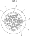
- FIG. 1 is a cross-sectional view, in a direction orthogonal to an axis, of an optical cable 1 according to the present embodiment.
- the optical cable 1 includes a plurality of optical fiber units 2, a water absorbing ribbon 3, a cable sheath 4, tensile strength members 5, and tear strings 6.
- the optical cable 1 is a so-called slot-less optical cable.
- the optical fiber unit 2 includes a plurality of optical fibers.
- An outer diameter of glass fibers provided in the plurality of optical fibers is, for example, 125 ⁇ m.
- An outer diameter of the optical fiber is, for example, any one of 165 ⁇ m, 200 ⁇ m, 220 ⁇ m, and 250 ⁇ m.
- the water absorbing ribbon 3 is wrapped around the entire periphery of the plurality of optical fiber units 2, for example, longitudinally or helically.
- the water absorbing ribbon 3 is, for example, a ribbon subjected to water absorption processing by applying a water absorption powder to a base fabric made of polyester or the like.
- the cable sheath 4 covers the periphery of the water absorbing ribbon 3.
- the cable sheath 4 is made of, for example, a resin such as polyvinyl chloride (PVC) or polyethylene (PE), and is formed by extrusion-molding the resin on the plurality of optical fiber units 2 around which the water absorbing ribbon 3 is wound.
- PVC polyvinyl chloride
- PE polyethylene
- the tensile strength members 5 are embedded in the cable sheath 4.
- the tensile strength members 5 are made of fiber reinforced plastic (FRP) such as aramid FRP, glass FRP, or carbon FRP.
- FRP fiber reinforced plastic
- the tensile strength members 5 may be formed of a liquid crystal polymer.
- the tensile strength members 5 are formed in a circular shape, in a cross-sectional view. Two tensile strength members 5 are provided inside the cable sheath 4 along a longitudinal direction of the optical cable 1.
- the tear strings 6 are for tearing the cable sheath 4, and is embedded in the cable sheath 4 along the longitudinal direction of the optical cable 1.
- two tear strings 6 are provided.
- the two tear strings 6 face each other at substantially intermediate positions of the two tensile strength members 5.
- the tear strings 6 are made of, for example, a plastic material (for example, polyester) resistant to tension.
- the plurality of optical fibers provided in the optical fiber unit 2 form a plurality of optical fiber ribbons 10.
- the plurality of optical fiber ribbons 10 are assembled in a bundled state or stranded state.
- the optical fiber unit 2 may not be in the form of an optical fiber ribbon, and may be an assembly of single optical fibers.
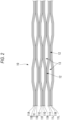
- FIG. 2 is a partially exploded view showing one optical fiber ribbon 10 in the longitudinal direction.
- the optical fiber ribbon 10 is an optical fiber ribbon with fiber adhesive parts and non-adhesive parts in which, in a state where a plurality of optical fibers 11A to 11L are arranged in parallel, a coupling portion 12 in a state where adjacent optical fibers are coupled and a non-coupling portion 13 in a state where adjacent optical fibers are not coupled are intermittently provided in the longitudinal direction. As shown in FIG.
- the coupling portion 12 and the non-coupling portion 13 are intermittently provided between some of the optical fibers (intermittent for every two fibers), but the coupling portion 12 and the non-coupling portion 13 may be intermittently provided between all of the optical fibers (intermittent for every one fiber).
- the optical fiber ribbons 10 in the optical fiber unit 2 may be stranded or may be stranded back.
- FIG. 3 is a schematic view showing a configuration in which the optical fiber ribbons 10 in the optical fiber unit 2 are stranded without the optical fiber ribbons 10 being stranded back.
- the optical cable 1 includes twelve optical fiber units 2, one of the twelve optical fiber units 2 is enlarged and shown in FIG. 3 for the sake of description.
- One optical fiber unit 2 is formed of three optical fiber ribbons 10 including twelve fibers. In order to make it easy to visually understand a strand angle of the optical fiber ribbon 10 described below, one of the three optical fiber ribbons 10 is shown in gradation in FIG. 3 .
- the optical fiber ribbons 10 in the optical fiber unit 2 are stranded in a clockwise direction R along the longitudinal direction of the optical cable.
- a strand angle of the optical fiber unit 2 shown in the lower part of FIG. 3 matches the strand angle of the three optical fiber ribbons 10.
- the optical fiber ribbons 10 in the optical fiber unit 2 are stranded in a counterclockwise direction L by periodically reversing the stranding direction. That is, the optical fiber ribbons 10 in the optical fiber unit 2 are SZ-stranded.
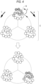
- FIG. 4 is a schematic view showing a configuration in which the optical fiber ribbons 10 in the optical fiber unit 2 are stranded while the optical fiber ribbons are stranded back.
- FIG. 4 is an enlarged view of one of the twelve optical fiber units 2 as in FIG. 3 . In order to make it easy to visually understand the strand angle of the optical fiber ribbons 10, one of the three optical fiber ribbons 10 is shown in gradation.
- the optical fiber ribbons 10 are stranded back in a counterclockwise direction S with respect to the stranding direction while being stranded in the clockwise direction R along the longitudinal direction of the optical cable 1.
- stranded back means that the optical fiber ribbons 10 of the optical fiber unit 2 are twisted in a direction to eliminate the twist of each optical fiber ribbon 10 that occurs when the optical fiber ribbons 10 of the optical fiber unit 2 are stranded. That is, when the optical fiber unit 2 before being stranded and the three optical fiber ribbons 10 shown in the upper part of FIG. 4 are used as a reference, the strand angle of the three optical fiber ribbons 10 shown in the lower part of FIG.
- FIG. 4 is smaller than the strand angle of the optical fiber unit 2 by an angle at which the optical fiber ribbons 10 are stranded back.
- a case of the strand back angle equivalent to the strand angle of the optical fiber unit 2 is shown, and a positional relationship of the three optical fiber ribbons 10 in the longitudinal direction of the cable changes, but the directions of the three optical fiber ribbons 10 do not change.
- the twist ratio of the stranding of the plurality of optical fiber units 2 is at least partially 0.0014 (rad/mm) or more. Accordingly, the PMD of the optical cable can be reduced to 0.1 ps/km 1/2 or less.
- the plurality of optical fiber units 2 are stranded while periodically reversing the stranding direction along the longitudinal direction of the optical cable.
- the twist ratio is at least partially set to 0.0014 (rad/mm) or more.
- the water absorbing ribbon 3 is longitudinally or helically wrapped around the periphery of the stranded plurality of optical fiber units 2, and the periphery thereof is covered with the cable sheath 4.
- the twist ratio of the stranding of the plurality of optical fiber units 2 is at least partially set to 0.0014 (rad/mm) or more, and thus it is possible to manufacture an optical cable in which the PMD is reduced to 0.1 ps/km 1/2 or less.
- the twist ratio may be set to 0.0100 (rad/mm) or less. Accordingly, it is possible to manufacture the optical cable 1 that reduces a decrease in melting workability due to an increase in the bending tendency of the plurality of optical fibers.
- the "0.0100 (rad/mm) or less" means that the upper limit value of the twist ratio is 0.0100 (rad/mm), and means that the twist ratio does not exceed 0.0100 (rad/mm) even in a part.
- Table 1 shows evaluation results of the PMD of the optical cable 1 according to the present disclosure.
- an optical fiber having an outer diameter of 200 ⁇ m and an optical fiber ribbon with fiber adhesive parts and non-adhesive parts are used.
- samples 1 to 5 a strand angle for each pitch between optical fiber units is changed to change a twist ratio.
- twist ratio indicates a twist ratio measured in a part of the optical cable 1.
- the SZ-stranding of the optical fiber ribbon in the optical fiber unit and the stranding back of the optical fiber units are performed in samples 1 to 5.
- a plurality of optical cables of such samples are manufactured, the PMD is measured, and a maximum value of the PMD is shown in the table.
- the PMD of the optical cable 1 can be reduced to 0.1 ps/km 1/2 or less.
- the twist ratio of the stranding is set to be larger than 0.0100 (rad/mm) in a part of the optical cable 1, the PMD is smaller, but the melting workability deteriorates.
- the twist ratio of the stranding is set to 0.0100 (rad/mm) or less, it is possible to prevent a decrease in the melting workability due to an increase in the bending tendency of the plurality of optical fibers.
Landscapes
- Physics & Mathematics (AREA)
- General Physics & Mathematics (AREA)
- Optics & Photonics (AREA)
- Engineering & Computer Science (AREA)
- Manufacturing & Machinery (AREA)
- Chemical & Material Sciences (AREA)
- Dispersion Chemistry (AREA)
- Light Guides In General And Applications Therefor (AREA)
- Communication Cables (AREA)
Abstract
Description
- The present disclosure relates to an optical cable and a method for manufacturing the optical cable.
- For example,
Patent Literature 1 discloses a unidirectional stranded slot-less optical cable in which polarization mode dispersion (PMD) is reduced.Patent Literature 2 discloses an SZ-stranded slot-less optical cable in which PMD is reduced. InPatent Literatures -
- Patent Literature 1:
JP2007-226051A - Patent Literature 2:
JP2002-122762A - A slot-less optical cable including:
- a plurality of optical fiber units each including a plurality of optical fibers; and
- a cable sheath covering the plurality of optical fiber units,
- in which the plurality of optical fiber units are stranded together along a longitudinal direction of the optical cable, and
- a twist ratio of the stranding of the plurality of optical fiber units is at least partially 0.0014 (rad/mm) or more.
- A method for manufacturing a slot-less optical cable that includes a plurality of optical fiber units each including a plurality of optical fibers, and a cable sheath covering the plurality of optical fiber units, the method including:
- a step of stranding the plurality of optical fiber units along a longitudinal direction of the optical cable; and
- a step of covering the plurality of optical fiber units with the cable sheath,
- in which in the step of stranding, a twist ratio of the stranding of the plurality of optical fiber units is at least partially set to 0.0014 (rad/mm) or more.
-
- [
FIG. 1] FIG. 1 is a cross-sectional view, in a direction orthogonal to an axis, of an optical cable according to the present embodiment. - [
FIG. 2] FIG. 2 is a partially exploded view showing one optical fiber ribbon in a longitudinal direction. - [
FIG. 3] FIG. 3 is a schematic view showing a configuration of an optical fiber unit in which a ribbon is not stranded back. - [
FIG. 4] FIG. 4 is a schematic view showing a configuration of an optical fiber unit in which a ribbon is stranded back. - In a slot-less optical cable formed by stranding a plurality of optical fibers, in a case where the plurality of optical fibers are in a form of an optical fiber ribbon, when a twist ratio of the strand of the optical fibers is large, a bending tendency of a ribbon increases, and there is a concern that melting workability decreases. In
Patent Literature 1, it is preferable that the twist ratio of the strand is 0.0104 (rad/mm) or more. However, when the twist ratio is too large, there is a possibility that the melting workability is deteriorated. - An object of the present disclosure is to provide an optical cable and a method for manufacturing the optical cable, which are capable of reducing PMD to a low level without deteriorating melting workability.
- According to the present disclosure, it is possible to provide an optical cable and a method for manufacturing the optical cable, which are capable of reducing PMD to a low level without deteriorating melting workability.
- An overview of an embodiment of the present disclosure will be described.
- (1) A slot-less optical cable includes:
- a plurality of optical fiber units each including a plurality of optical fibers; and
- a cable sheath covering the plurality of optical fiber units, in which
- the plurality of optical fiber units are stranded together along a longitudinal direction of the optical cable, and
- a twist ratio of the stranding of the plurality of optical fiber units is at least partially 0.0014 (rad/mm) or more.
- According to the above configuration, when the twist ratio of the stranding of the plurality of optical fiber units is at least partially set to 0.0014 (rad/mm) or more, PMD of the optical cable can be reduced to 0.1 ps/km1/2 or less without being greatly twisted. In addition, with such a degree of the twist ratio, a bending tendency of the plurality of optical fibers increases, and thus melting workability does not decrease.
- The twist ratio is a maximum value of a twist amount per unit length of the optical fiber unit, and is, for example, a maximum value (maximum angle) when a twist amount (angle) of the unit is measured every 1 cm by peeling off a sheath in a range of 1 m.
- (2) In the optical cable according to item (1), the plurality of optical fibers include optical fibers having an outer diameter of 220 µm or less, and the plurality of optical fibers form an optical fiber ribbon with fiber adhesive parts and non-adhesive parts in which, a coupling portion and a non-coupling portion are intermittently provided in the longitudinal direction in a state where the plurality of optical fibers are arranged in parallel in a direction orthogonal to the longitudinal direction, the coupling portion being a state where adjacent optical fibers of some or all of the plurality of optical fibers are coupled, the non-coupling portion being a state where the adjacent optical fibers are not coupled.
- According to the above configuration, even when the plurality of optical fibers are accommodated at a high density, an increase in transmission loss is unlikely to occur, and when the optical fibers are taken out, a single fiber separation operation is easily performed.
- (3) In the optical cable according to item (1) or (2), an upper limit value of the twist ratio is 0.0100 (rad/mm) or less.
- According to the above configuration, it is possible to prevent a decrease in melting workability due to an increase in the bending tendency of the plurality of optical fibers.
- (4) In the optical cable according to item (3), the plurality of optical fiber units are stranded back in the stranding direction.
- According to the above configuration, it is possible to eliminate the twist of each optical fiber occurring when the plurality of optical fiber units are stranded.
- (5) In a method for manufacturing a slot-less optical cable that includes a plurality of optical fiber units each including a plurality of optical fibers, and a cable sheath covering the plurality of optical fiber units, the method includes:
- a step of stranding the plurality of optical fiber units along a longitudinal direction of the optical cable; and
- a step of covering the plurality of optical fiber units with the cable sheath,
- in the step of stranding, a twist ratio of the stranding of the plurality of optical fiber units is at least partially set to 0.0014 (rad/mm) or more.
- According to the above method, in the step of stranding the plurality of optical fiber units, the twist ratio of the stranding of the plurality of optical fiber units is at least partially set to 0.0014 (rad/mm) or more, and thus it is possible to manufacture an optical cable in which PMD is reduced to 0.1 ps/km1/2 or less.
- (6) In the method for manufacturing an optical cable according to item (5), in the step of stranding, an upper limit value of the twist ratio is set to 0.0100 (rad/mm) or less.
- According to the above method, it is possible to manufacture an optical cable that reduces a decrease in melting workability due to an increase in the bending tendency of the plurality of optical fibers.
- (7) In the method for manufacturing an optical cable according to any one of items (1) to (6), the step of stranding includes a step of stranding back the plurality of optical fiber units in the stranding direction.
- According to the above method, it is possible to manufacture an optical cable in which the twist of each optical fiber occurring when the plurality of optical fiber units are stranded is eliminated.
- Hereinafter, an embodiment of the present disclosure will be described with reference to the drawings. Members having the same reference numerals as those members already described in description of the present embodiment will not be described for convenience of description. Dimensions of the members shown in the drawings are for convenience of description and may be different from actual dimensions of the members.
-
FIG. 1 is a cross-sectional view, in a direction orthogonal to an axis, of anoptical cable 1 according to the present embodiment. As shown inFIG. 1 , theoptical cable 1 includes a plurality ofoptical fiber units 2, awater absorbing ribbon 3, a cable sheath 4,tensile strength members 5, andtear strings 6. Theoptical cable 1 is a so-called slot-less optical cable. - The
optical fiber unit 2 includes a plurality of optical fibers. An outer diameter of glass fibers provided in the plurality of optical fibers is, for example, 125 µm. An outer diameter of the optical fiber is, for example, any one of 165 µm, 200 µm, 220 µm, and 250 µm. - The
water absorbing ribbon 3 is wrapped around the entire periphery of the plurality ofoptical fiber units 2, for example, longitudinally or helically. Thewater absorbing ribbon 3 is, for example, a ribbon subjected to water absorption processing by applying a water absorption powder to a base fabric made of polyester or the like. - The cable sheath 4 covers the periphery of the
water absorbing ribbon 3. The cable sheath 4 is made of, for example, a resin such as polyvinyl chloride (PVC) or polyethylene (PE), and is formed by extrusion-molding the resin on the plurality ofoptical fiber units 2 around which thewater absorbing ribbon 3 is wound. - The
tensile strength members 5 are embedded in the cable sheath 4. Thetensile strength members 5 are made of fiber reinforced plastic (FRP) such as aramid FRP, glass FRP, or carbon FRP. Thetensile strength members 5 may be formed of a liquid crystal polymer. - The
tensile strength members 5 are formed in a circular shape, in a cross-sectional view. Twotensile strength members 5 are provided inside the cable sheath 4 along a longitudinal direction of theoptical cable 1. - The tear strings 6 are for tearing the cable sheath 4, and is embedded in the cable sheath 4 along the longitudinal direction of the
optical cable 1. In this example, twotear strings 6 are provided. The twotear strings 6 face each other at substantially intermediate positions of the twotensile strength members 5. By pulling out the tear strings 6, the cable sheath 4 is torn in the longitudinal direction, and theoptical fiber unit 2 can be taken out. The tear strings 6 are made of, for example, a plastic material (for example, polyester) resistant to tension. - The plurality of optical fibers provided in the
optical fiber unit 2 form a plurality ofoptical fiber ribbons 10. The plurality ofoptical fiber ribbons 10 are assembled in a bundled state or stranded state. - The
optical fiber unit 2 may not be in the form of an optical fiber ribbon, and may be an assembly of single optical fibers. -
FIG. 2 is a partially exploded view showing oneoptical fiber ribbon 10 in the longitudinal direction. Theoptical fiber ribbon 10 is an optical fiber ribbon with fiber adhesive parts and non-adhesive parts in which, in a state where a plurality ofoptical fibers 11A to 11L are arranged in parallel, acoupling portion 12 in a state where adjacent optical fibers are coupled and anon-coupling portion 13 in a state where adjacent optical fibers are not coupled are intermittently provided in the longitudinal direction. As shown inFIG. 2 , in theoptical fiber ribbon 10, twelveoptical fibers 11A to 11L are arranged in parallel, and thenon-coupling portions 13 are not provided between theoptical fibers coupling portion 12 and thenon-coupling portion 13 are intermittently provided between some of the optical fibers (intermittent for every two fibers), but thecoupling portion 12 and thenon-coupling portion 13 may be intermittently provided between all of the optical fibers (intermittent for every one fiber). - The
optical fiber ribbons 10 in theoptical fiber unit 2 may be stranded or may be stranded back.FIG. 3 is a schematic view showing a configuration in which theoptical fiber ribbons 10 in theoptical fiber unit 2 are stranded without theoptical fiber ribbons 10 being stranded back. Although theoptical cable 1 includes twelveoptical fiber units 2, one of the twelveoptical fiber units 2 is enlarged and shown inFIG. 3 for the sake of description. Oneoptical fiber unit 2 is formed of threeoptical fiber ribbons 10 including twelve fibers. In order to make it easy to visually understand a strand angle of theoptical fiber ribbon 10 described below, one of the threeoptical fiber ribbons 10 is shown in gradation inFIG. 3 . - As shown in
FIG. 3 , theoptical fiber ribbons 10 in theoptical fiber unit 2 are stranded in a clockwise direction R along the longitudinal direction of the optical cable. At this time, since the optical fiber ribbon is not stranded back, when theoptical fiber unit 2 shown in the upper part ofFIG. 3 and the threeoptical fiber ribbons 10 are used as a reference, a strand angle of theoptical fiber unit 2 shown in the lower part ofFIG. 3 matches the strand angle of the threeoptical fiber ribbons 10. Although not shown inFIG. 3 , theoptical fiber ribbons 10 in theoptical fiber unit 2 are stranded in a counterclockwise direction L by periodically reversing the stranding direction. That is, theoptical fiber ribbons 10 in theoptical fiber unit 2 are SZ-stranded. -
FIG. 4 is a schematic view showing a configuration in which theoptical fiber ribbons 10 in theoptical fiber unit 2 are stranded while the optical fiber ribbons are stranded back.FIG. 4 is an enlarged view of one of the twelveoptical fiber units 2 as inFIG. 3 . In order to make it easy to visually understand the strand angle of theoptical fiber ribbons 10, one of the threeoptical fiber ribbons 10 is shown in gradation. - As shown in
FIG. 4 , in theoptical fiber unit 2, theoptical fiber ribbons 10 are stranded back in a counterclockwise direction S with respect to the stranding direction while being stranded in the clockwise direction R along the longitudinal direction of theoptical cable 1. Here, "stranded back" means that theoptical fiber ribbons 10 of theoptical fiber unit 2 are twisted in a direction to eliminate the twist of eachoptical fiber ribbon 10 that occurs when theoptical fiber ribbons 10 of theoptical fiber unit 2 are stranded. That is, when theoptical fiber unit 2 before being stranded and the threeoptical fiber ribbons 10 shown in the upper part ofFIG. 4 are used as a reference, the strand angle of the threeoptical fiber ribbons 10 shown in the lower part ofFIG. 4 is smaller than the strand angle of theoptical fiber unit 2 by an angle at which theoptical fiber ribbons 10 are stranded back. In the example ofFIG. 4 , a case of the strand back angle equivalent to the strand angle of theoptical fiber unit 2 is shown, and a positional relationship of the threeoptical fiber ribbons 10 in the longitudinal direction of the cable changes, but the directions of the threeoptical fiber ribbons 10 do not change. - In the present embodiment, the twist ratio of the stranding of the plurality of
optical fiber units 2 is at least partially 0.0014 (rad/mm) or more. Accordingly, the PMD of the optical cable can be reduced to 0.1 ps/km1/2 or less. - A method for manufacturing the optical cable according to the present embodiment will be described. The plurality of
optical fiber units 2 are stranded while periodically reversing the stranding direction along the longitudinal direction of the optical cable. When the plurality ofoptical fiber units 2 are stranded, the twist ratio is at least partially set to 0.0014 (rad/mm) or more. Thereafter, thewater absorbing ribbon 3 is longitudinally or helically wrapped around the periphery of the stranded plurality ofoptical fiber units 2, and the periphery thereof is covered with the cable sheath 4. In the stranding step, the twist ratio of the stranding of the plurality ofoptical fiber units 2 is at least partially set to 0.0014 (rad/mm) or more, and thus it is possible to manufacture an optical cable in which the PMD is reduced to 0.1 ps/km1/2 or less. - Further, in the step pf stranding, the twist ratio may be set to 0.0100 (rad/mm) or less. Accordingly, it is possible to manufacture the
optical cable 1 that reduces a decrease in melting workability due to an increase in the bending tendency of the plurality of optical fibers. - The "0.0100 (rad/mm) or less" means that the upper limit value of the twist ratio is 0.0100 (rad/mm), and means that the twist ratio does not exceed 0.0100 (rad/mm) even in a part.
- Table 1 shows evaluation results of the PMD of the
optical cable 1 according to the present disclosure. In optical cable samples to be evaluated, an optical fiber having an outer diameter of 200 µm and an optical fiber ribbon with fiber adhesive parts and non-adhesive parts are used. Insamples 1 to 5, a strand angle for each pitch between optical fiber units is changed to change a twist ratio. - In Table 1, "strand back of ribbon" indicates strand back of the optical fiber ribbon in the optical fiber unit, "stranding direction" indicates a stranding direction of the optical fiber units, and "twist ratio" indicates a twist ratio of the optical fiber units. The twist ratio is a twist ratio measured in a part of the
optical cable 1. The SZ-stranding of the optical fiber ribbon in the optical fiber unit and the stranding back of the optical fiber units are performed insamples 1 to 5. - A plurality of optical cables of such samples are manufactured, the PMD is measured, and a maximum value of the PMD is shown in the table.
- Even in the
sample 5 without stranding back of the ribbon, similarly to the samples with stranding back, it is confirmed that the PMD is reduced to 0.1 ps/km1/2 or less by setting the twist ratio of the optical fiber units to 0.0014 (rad/mm) or more. However, since the twist occurs, when the twist ratio is too large, the melting workability may deteriorate. When the optical fiber units are spirally stranded, similarly to the case where the optical fiber units are SZ-stranded, it is expected that the PMD of the optical cable is reduced to 0.1 ps/km1/2 or less by setting the twist ratio to 0.0014 (rad/mm) or more.[Table 1] Sample No. Strand back of ribbon Stranding direction Twist ratio (rad/mm) MAX PMD (ps/km1/2) 1 Yes SZ-strand 0.0042 0.0815 2 Yes SZ-strand 0.0028 0.0889 3 Yes SZ-strand 0.0014 0.0987 4 Yes SZ-strand 0.0010 0.1012 5 No SZ-strand 0.0014 0.0971 - As shown in Table 1, in a part of the
optical cable 1, by setting the twist ratio of the stranding to 0.0014 (rad/mm) or more, the PMD of theoptical cable 1 can be reduced to 0.1 ps/km1/2 or less. However, when the twist ratio is less than 0.0014 (rad/mm) in a part of theoptical cable 1, the PMD cannot be set to 0.1 ps/km1/2 or less. When the twist ratio of the stranding is set to be larger than 0.0100 (rad/mm) in a part of theoptical cable 1, the PMD is smaller, but the melting workability deteriorates. As described above, by setting the twist ratio of the stranding to 0.0100 (rad/mm) or less, it is possible to prevent a decrease in the melting workability due to an increase in the bending tendency of the plurality of optical fibers. - Although the embodiment of the present disclosure has been described above, it goes without saying that the technical scope of the present disclosure should not be interpreted to be limited by the description of the present embodiment. The present embodiment is merely an example, and it is understood by those skilled in the art that various modifications to the present embodiment can be made within the scope of the invention described in the claims. As described above, the technical scope of the present disclosure should be defined based on the scope of the invention described in the claims and the scope of equivalents thereof.
- The present application claims priority based on
Japanese Patent Application No. 2021-210965 filed on December 24, 2021 -
- 1: optical cable
- 2: optical fiber unit
- 3: water absorbing ribbon
- 4: cable sheath
- 5: tensile strength member
- 6: tear string
- 10: optical fiber ribbon
- 11A to 11L: optical fiber
- 12: coupling portion
- 13: non-coupling portion
- R: clockwise direction
- L: counterclockwise direction
- S: counterclockwise direction
Claims (7)
- A slot-less optical cable comprising:a plurality of optical fiber units each including a plurality of optical fibers; anda cable sheath covering the plurality of optical fiber units,wherein the plurality of optical fiber units are stranded together along a longitudinal direction of the optical cable, anda twist ratio of the stranding of the plurality of optical fiber units is at least partially 0.0014 (rad/mm) or more.
- The optical cable according to claim 1,wherein the plurality of optical fibers include optical fibers having an outer diameter of 220 µm or less, andthe plurality of optical fibers form an optical fiber ribbon with fiber adhesive parts and non-adhesive parts in which a coupling portion and a non-coupling portion are intermittently provided in the longitudinal direction in a state where the plurality of optical fibers are arranged in parallel in a direction orthogonal to the longitudinal direction, the coupling portion being a state where adjacent optical fibers of some or all of the plurality of optical fibers are coupled, the non-coupling portion being a state where the adjacent optical fibers are not coupled.
- The optical cable according to claim 1 or 2,
wherein an upper limit value of the twist ratio is 0.0100 (rad/mm) or less. - The optical cable according to any one of claims 1 to 3,
wherein the plurality of optical fiber units are stranded back in the stranding direction. - A method for manufacturing a slot-less optical cable that includes a plurality of optical fiber units each including a plurality of optical fibers, and a cable sheath covering the plurality of optical fiber units, the method comprising:a step of stranding the plurality of optical fiber units along a longitudinal direction of the optical cable; anda step of covering the plurality of optical fiber units with the cable sheath,wherein in the step of stranding, a twist ratio of the stranding of the plurality of optical fiber units is at least partially set to 0.0014 (rad/mm) or more.
- The method for manufacturing an optical cable according to claim 5,
wherein in the step of stranding, an upper limit value of the twist ratio is set to 0.0100 (rad/mm) or less. - The method for manufacturing an optical cable according to claim 5 or 6,
wherein the step of stranding includes a step of stranding back the plurality of optical fiber units in the stranding direction.
Applications Claiming Priority (2)
| Application Number | Priority Date | Filing Date | Title |
|---|---|---|---|
| JP2021210965 | 2021-12-24 | ||
| PCT/JP2022/047758 WO2023120727A1 (en) | 2021-12-24 | 2022-12-23 | Optical cable and method for manufacturing optical cable |
Publications (2)
| Publication Number | Publication Date |
|---|---|
| EP4455751A1 true EP4455751A1 (en) | 2024-10-30 |
| EP4455751A4 EP4455751A4 (en) | 2025-05-07 |
Family
ID=86902892
Family Applications (1)
| Application Number | Title | Priority Date | Filing Date |
|---|---|---|---|
| EP22911428.5A Pending EP4455751A4 (en) | 2021-12-24 | 2022-12-23 | OPTICAL CABLE AND METHOD FOR MANUFACTURING OPTICAL CABLE |
Country Status (4)
| Country | Link |
|---|---|
| US (1) | US20250138268A1 (en) |
| EP (1) | EP4455751A4 (en) |
| JP (1) | JPWO2023120727A1 (en) |
| WO (1) | WO2023120727A1 (en) |
Families Citing this family (2)
| Publication number | Priority date | Publication date | Assignee | Title |
|---|---|---|---|---|
| WO2025163794A1 (en) * | 2024-01-31 | 2025-08-07 | 住友電気工業株式会社 | Optical fiber cable |
| WO2026022974A1 (en) * | 2024-07-24 | 2026-01-29 | 住友電気工業株式会社 | Optical cable and method for manufacturing optical cable |
Family Cites Families (10)
| Publication number | Priority date | Publication date | Assignee | Title |
|---|---|---|---|---|
| JP2002122762A (en) | 2000-08-11 | 2002-04-26 | Furukawa Electric Co Ltd:The | Fiber optic cable |
| JP2007108424A (en) * | 2005-10-13 | 2007-04-26 | Sumitomo Electric Ind Ltd | Optical cable |
| JP4893024B2 (en) * | 2006-02-24 | 2012-03-07 | 住友電気工業株式会社 | Optical cable |
| WO2010051856A1 (en) * | 2008-11-07 | 2010-05-14 | Prysmian S.P.A. | Bend-insensitive optical cable |
| JP2012027392A (en) * | 2010-07-27 | 2012-02-09 | Sumitomo Electric Ind Ltd | Manufacturing method of optical fiber ribbon and manufacturing apparatus |
| US10514517B2 (en) * | 2015-07-31 | 2019-12-24 | Sumitomo Electric Industries, Ltd. | Optical fiber cable |
| JP6840659B2 (en) * | 2017-12-19 | 2021-03-10 | 株式会社フジクラ | Fiber optic cable |
| HUE067399T2 (en) * | 2018-10-11 | 2024-10-28 | Fujikura Ltd | Optical fiber cable |
| EP3943992B1 (en) * | 2019-03-20 | 2025-07-23 | Sumitomo Electric Industries, Ltd. | Intermittent connection-type optical fiber tape core, optical fiber cable and connector-equipped optical fiber cord |
| JP7426873B2 (en) * | 2020-03-27 | 2024-02-02 | 古河電気工業株式会社 | fiber optic cable |
-
2022
- 2022-12-23 US US18/722,699 patent/US20250138268A1/en active Pending
- 2022-12-23 JP JP2023569587A patent/JPWO2023120727A1/ja active Pending
- 2022-12-23 WO PCT/JP2022/047758 patent/WO2023120727A1/en not_active Ceased
- 2022-12-23 EP EP22911428.5A patent/EP4455751A4/en active Pending
Also Published As
| Publication number | Publication date |
|---|---|
| US20250138268A1 (en) | 2025-05-01 |
| EP4455751A4 (en) | 2025-05-07 |
| JPWO2023120727A1 (en) | 2023-06-29 |
| WO2023120727A1 (en) | 2023-06-29 |
Similar Documents
| Publication | Publication Date | Title |
|---|---|---|
| EP3879323B1 (en) | Optical fiber cable | |
| US9651753B2 (en) | Fiber optic ribbon cable | |
| EP1895340B1 (en) | A loose tube optical waveguide fiber cable | |
| US20060072886A1 (en) | Loose tube optical cable | |
| EP4455751A1 (en) | Optical cable and method for manufacturing optical cable | |
| US4093342A (en) | Optical fiber cable | |
| EP3207415B1 (en) | Central loose tube optical-fiber cable | |
| CN101120277A (en) | Low shrinkage telecommunications optical cable and method of manufacturing the same | |
| EP3304156B1 (en) | Optical cable for terrestrial networks | |
| EP4279965A1 (en) | Optical fiber cable and connector-equipped cable | |
| US20020181906A1 (en) | Fiber optic cables having ultra-low shrinking filaments and methods of making the same | |
| KR100526506B1 (en) | Optical cable for air blow installation | |
| CN102016673A (en) | Multi-fiber fiber optic cable | |
| US20220390701A1 (en) | Optical fiber cable and method for manufacturing optical fiber cable | |
| KR102735442B1 (en) | Optical cable | |
| US8630521B2 (en) | Optical cable | |
| KR102822837B1 (en) | Optic cable | |
| JP2008197258A (en) | Optical cable | |
| CN103097933A (en) | Plastic optical fiber unit and plastic optical fiber cable using same | |
| US20230194817A1 (en) | Optical fiber cable with coil elements | |
| CN215813480U (en) | High-strength high-flame-retardant flexible indoor optical cable | |
| CN116075760A (en) | Optical cable and method for manufacturing optical cable | |
| CN219512456U (en) | Large-core-number discrete biological protection optical cable | |
| CN219641982U (en) | Elevator trailing optical cable | |
| US20250004236A1 (en) | Optical cable, optical cable structure, and method for manufacturing optical cable |
Legal Events
| Date | Code | Title | Description |
|---|---|---|---|
| STAA | Information on the status of an ep patent application or granted ep patent |
Free format text: STATUS: THE INTERNATIONAL PUBLICATION HAS BEEN MADE |
|
| PUAI | Public reference made under article 153(3) epc to a published international application that has entered the european phase |
Free format text: ORIGINAL CODE: 0009012 |
|
| STAA | Information on the status of an ep patent application or granted ep patent |
Free format text: STATUS: REQUEST FOR EXAMINATION WAS MADE |
|
| 17P | Request for examination filed |
Effective date: 20240621 |
|
| AK | Designated contracting states |
Kind code of ref document: A1 Designated state(s): AL AT BE BG CH CY CZ DE DK EE ES FI FR GB GR HR HU IE IS IT LI LT LU LV MC ME MK MT NL NO PL PT RO RS SE SI SK SM TR |
|
| DAV | Request for validation of the european patent (deleted) | ||
| DAX | Request for extension of the european patent (deleted) | ||
| A4 | Supplementary search report drawn up and despatched |
Effective date: 20250404 |
|
| RIC1 | Information provided on ipc code assigned before grant |
Ipc: G02B 6/02 20060101ALI20250331BHEP Ipc: G02B 6/44 20060101AFI20250331BHEP |