EP4455743A1 - Microlens array, light-emitting device, and sensor module - Google Patents
Microlens array, light-emitting device, and sensor module Download PDFInfo
- Publication number
- EP4455743A1 EP4455743A1 EP22911289.1A EP22911289A EP4455743A1 EP 4455743 A1 EP4455743 A1 EP 4455743A1 EP 22911289 A EP22911289 A EP 22911289A EP 4455743 A1 EP4455743 A1 EP 4455743A1
- Authority
- EP
- European Patent Office
- Prior art keywords
- lenses
- lens
- vertex
- microlens array
- light
- Prior art date
- Legal status (The legal status is an assumption and is not a legal conclusion. Google has not performed a legal analysis and makes no representation as to the accuracy of the status listed.)
- Withdrawn
Links
Images




Classifications
-
- G—PHYSICS
- G02—OPTICS
- G02B—OPTICAL ELEMENTS, SYSTEMS OR APPARATUS
- G02B3/00—Simple or compound lenses
- G02B3/0006—Arrays
- G02B3/0037—Arrays characterized by the distribution or form of lenses
- G02B3/0043—Inhomogeneous or irregular arrays, e.g. varying shape, size, height
-
- G—PHYSICS
- G02—OPTICS
- G02B—OPTICAL ELEMENTS, SYSTEMS OR APPARATUS
- G02B3/00—Simple or compound lenses
- G02B3/0006—Arrays
- G02B3/0037—Arrays characterized by the distribution or form of lenses
- G02B3/0056—Arrays characterized by the distribution or form of lenses arranged along two different directions in a plane, e.g. honeycomb arrangement of lenses
-
- G—PHYSICS
- G02—OPTICS
- G02B—OPTICAL ELEMENTS, SYSTEMS OR APPARATUS
- G02B5/00—Optical elements other than lenses
- G02B5/02—Diffusing elements; Afocal elements
- G02B5/0205—Diffusing elements; Afocal elements characterised by the diffusing properties
- G02B5/021—Diffusing elements; Afocal elements characterised by the diffusing properties the diffusion taking place at the element's surface, e.g. by means of surface roughening or microprismatic structures
- G02B5/0215—Diffusing elements; Afocal elements characterised by the diffusing properties the diffusion taking place at the element's surface, e.g. by means of surface roughening or microprismatic structures the surface having a regular structure
-
- H—ELECTRICITY
- H10—SEMICONDUCTOR DEVICES; ELECTRIC SOLID-STATE DEVICES NOT OTHERWISE PROVIDED FOR
- H10F—INORGANIC SEMICONDUCTOR DEVICES SENSITIVE TO INFRARED RADIATION, LIGHT, ELECTROMAGNETIC RADIATION OF SHORTER WAVELENGTH OR CORPUSCULAR RADIATION
- H10F55/00—Radiation-sensitive semiconductor devices covered by groups H10F10/00, H10F19/00 or H10F30/00 being structurally associated with electric light sources and electrically or optically coupled thereto
-
- H—ELECTRICITY
- H10—SEMICONDUCTOR DEVICES; ELECTRIC SOLID-STATE DEVICES NOT OTHERWISE PROVIDED FOR
- H10F—INORGANIC SEMICONDUCTOR DEVICES SENSITIVE TO INFRARED RADIATION, LIGHT, ELECTROMAGNETIC RADIATION OF SHORTER WAVELENGTH OR CORPUSCULAR RADIATION
- H10F77/00—Constructional details of devices covered by this subclass
- H10F77/40—Optical elements or arrangements
-
- G—PHYSICS
- G02—OPTICS
- G02B—OPTICAL ELEMENTS, SYSTEMS OR APPARATUS
- G02B3/00—Simple or compound lenses
- G02B2003/0093—Simple or compound lenses characterised by the shape
Definitions
- the present disclosure relates to a microlens array, a light-emitting device, and a sensor module.
- Japanese Unexamined Patent Application Publication No. 2003-4907 discloses a microlens array including multiple lenses located such that the vertex distances of the lenses are located in an irregular manner.
- a microlens array includes:
- a light-emitting device includes:
- a sensor module includes:
- FIG. 1A is a vertical cross-sectional view of a microlens array according to an embodiment of the present invention.
- FIG. 1B is a plan view of the microlens array.
- FIG. 1A illustrates a cross section taken along line A-A in FIG. 1B .
- the microlens array 1A of Embodiment 1 includes multiple lenses 10.
- Each lens 10 may be a convex lens including a vertex on its one side.
- the multiple lenses 10 may be arranged parallel with a plane S1 (a flat plane in FIG. 1A ) in two-dimensional directions, and each lens 10 may have the optical axis (in other words, the main axis) in the direction normal to the plane S1.
- the multiple lenses 10 may be connected with one another on the plane S1 side.
- the multiple lenses 10 may have a unitary structure, which is integrally molded.
- the microlens array 1A may include a transparent substrate 2 such as a glass substrate so that the multiple lenses 10 are located on the transparent substrate 2.
- the microlens array 1A if light enters the microlens array 1A from its one side (specifically, the side on which the vertices of the lenses 10 are located in the Z direction), the light is refracted by the multiple lenses 10, and diffused light can be emitted from the other face of the microlens array 1A.
- FIG. 2 is a diagram for explaining a region where a second lens is located in the microlens array of Embodiment 1.
- the height from a certain reference plane to the vertex of a lens is referred to as "vertex height".
- the reference plane may be any plane parallel to the plane S1 on which the multiple lenses 10 are arrayed.
- a range in which a lens's curved surface (for example, a convex curved surface) continues is regarded as one lens 10.
- a peripheral edge at which a lens curved surface has a sharp change, for example, a valley at which a lens curved surface intersects another adjacent lens 10 denotes a boundary of one lens 10.
- a bend portion at which a lens curved surface intersects a surface other than a lens curved surface denotes a boundary of one lens 10.
- the bend portion mentioned above does not refer to a bend portion in a strict sense and is a concept including a bend portion including small roundness.
- the length in the optical axis direction from the lowermost end of the boundaries of one lens 10 to the uppermost end of the lens 10 (which, for example, if the lens 10 has a vertex, refers to the vertex) is referred to as "the vertical dimension of the lens".
- the multiple lenses 10 may include multiple first lenses 11 having vertex heights higher than or equal to a first vertex height H1 (see FIG. 2 ) and one or more second lenses 12 having vertex heights lower than the first vertex height H1 (see FIGs. 1A and 1B ).
- the first lenses 11 and the second lenses 12 may have distinct differences in vertex heights. Specifically, the maximum value of the vertical dimensions of the one or more second lenses 12 may be smaller than or equal to the minimum value of the vertical dimensions of the multiple first lenses 11. The multiple first lenses 11 may have variations in vertex heights.
- the multiple first lenses 11 may have the first vertex height H1 as illustrated in FIG. 2 .
- the vertex heights of the first lenses 11 may be in agreement with the first vertex height H1.
- the word "agreement” denotes not only “agreement in a strict sense” but is a concept including cases in which the variations are within a specified error.
- the range of the error in this context may be a range from the first vertex height H1 to (the first vertex height H1 + 15% of the reference vertical dimension (described later) of the first lenses 11).
- This configuration enables first lenses 11 having the same or similar vertex heights to be located in multiple regions of the microlens array 1A and hence enables the multiple regions to have the same or similar light distribution characteristics by the first lenses 11.
- the multiple first lenses 11 may have the same size and the same lens shape. This configuration makes it more likely for the multiple regions of the microlens array 1A to have the same or similar light distribution characteristics.
- the words "the same size and the same lens shape” denote not only “agreement in a strict sense” but is a concept including cases in which the variations are within a specified error.
- the error denotes that the maximum difference in the sag of each point is within 15% of the reference vertical dimension (described later) of the first lenses 11 as compared with that of the curved surface of one lens. Even if the boundary positions of lens curved surfaces are different, if the shapes in the boundaries are the same, the shapes of the curved surfaces can be regarded as being the same.
- the microlens array 1A may include a first region R1 in which the vertex distance Lp is smaller than a threshold THp and a second region R2 in which the vertex distance Lp is larger than the threshold THp.
- This configuration causes variations in the vertex distances of the first lenses 11.
- this configuration reduces the effect that light beams having passed through the multiple first lenses 11 are overlayed regularly and cause interference fringes, and provides favorable light distribution characteristics.
- plane view denote viewing in the direction orthogonal to the plane S1.
- the microlens array 1A may include a third region R3 in which the vertex distance is smaller than the threshold THp and a fourth region R4 in which the vertex distance is larger than the threshold THp. Also this configuration causes variations in the vertex distances of the first lenses 11. Hence, this configuration reduces the effect that light beams having passed through the multiple first lenses 11 are overlayed regularly and cause interference fringes, and provides favorable light distribution characteristics.
- a second lens 12 may be located between two first lenses 11 in a second region R2 in which the vertex distance is larger than the threshold THp.
- a second lens 12 may be located between multiple first lenses 11 in a region where the second region R2 and fourth region R4 in which the vertex distance is larger than the threshold THp overlap each other.
- the threshold THp mentioned above may be set to be smaller than or equal to a vertex distance corresponding to a depth Hx, which is the depth of the valley between two adjacent first lenses 11, and at which a molding difficult portion D1 of lens curved surfaces appears.
- the vertex distance corresponding to the depth Hx refers to the distance of vertices the valley between which reaches the depth Hx.
- This setting provides favorable light distribution characteristics. This is because if a second lens 12 is not present in the second region R2, the fourth region R4, or the like where the distance between adjacent first lenses 11 is large, the valley there is deep. Hence, molding lens curved surfaces is difficult in many valleys.
- a second lens 12 is present between multiple first lenses 11 in the second region R2 or the fourth region R4, it reduces deep valleys where molding lens curved surfaces is difficult. This makes it easier to form required lens curved surfaces and makes it possible to provide the microlens array 1A with favorable light distribution characteristics.
- the threshold THp mentioned above may be set to be smaller than or equal to a vertex distance corresponding to a depth Hy, which is the depth of the valley between two adjacent first lenses 11, and at which a bottom portion D2 which is out of the requirement for the first lens 11 appears.
- the vertex distance corresponding to the depth Hy refers to the distance of vertices the valley between which reaches the depth Hy.
- the lens shape of the first lens 11 is designed so as to provide required light distribution characteristics. However, this lens shape corresponds to the lens shape having a width smaller than or equal to a specified width of the first lens 11. If light passes through the bottom portion D2 out of the specified width, there is a possibility that the light can deviate from the required light distribution characteristics. Hence, the above setting reduces first lenses 11 including the bottom portion D2 and makes it possible to provide favorable light distribution characteristics.
- the configuration described above also provides an advantage that makes it easier to achieve light distribution characteristics having a wide diffusion angle. If second lenses 12 are not present, it limits the aspect ratio (specifically, the vertical dimension/the horizontal dimension) of the first lens 11 to reduce deep valleys where molding lens curved surfaces is difficult. However, the presence of second lenses 12 mitigates the limitation to the aspect ratio of the first lens 11, making it possible to increase the aspect ratio of the first lens 11. This makes it easier to achieve light distribution characteristics having a wide diffusion angle.
- the second lenses 12 may have vertex heights lower than the vertex heights of the first lenses 11. This configuration makes the ratio of the area where the second lenses 12 occupy in the microlens array 1A smaller than the ratio of the area where the first lenses 11 occupy in the microlens array 1A. Accordingly, in the light diffusion effect of the microlens array 1A, the ratio of the light diffusion effect caused by the second lenses 12 is smaller than the ratio of the light diffusion effect caused by the multiple first lenses 11. This reduces deviations of the light distribution characteristics of the microlens array 1A from the required characteristics, caused by the second lenses 12.
- a second lens 12 may be located such that its vertex appears between multiple first lenses 11 or such that a lens curved surface not including its vertex appears between multiple first lenses 11.
- a pass-through region Rc (see FIG. 13 ) is set in the microlens array 1A, all of the outer periphery of each lens 10 may be in contact with another adjacent lens 10 in at least the pass-through region Rc.
- the pass-through region Rc may be specified in, for example, a specification or the like as a region that light passes through. In this configuration, since surfaces (for example, flat surfaces) other than lens curved surfaces are not present in the boundaries between the lenses 10 in the pass-through region Rc, more favorable light distribution characteristics can be achieved.
- the multiple lenses 10 may include a third lens (for example, a convex lens) different from the first lenses 11 and the second lenses 12.
- a second lens 12 need not be located all of the second and fourth regions R2 and R4 in which the vertex distance is large. In the second and fourth regions R2 and R4 in which the vertex distance is large, the higher the rate of a second lens 12 being present, the higher the effect of second lenses 12.
- FIG. 3 is a diagram for explaining the vertex heights of second lenses of a microlens array of Embodiment 2.
- the vertex heights of the second lenses 12 differ from those in Embodiment 1, and other constituents are the same as or similar to those in Embodiment 1. Detailed description of the same or similar constituents is omitted.
- FIG. 4 is a plan view of a microlens array in which first lenses are imaginarily arranged in a regular manner without changing the average value of vertex densities.
- FIGs. 3 and 4 illustrate first lenses 11 before regular arrangement and first lenses 11v after regular arrangement with different symbols.
- a regular arrangement denotes that the vertices of multiple first lenses 11 are arranged in a regular manner in plan view. In a regular arrangement, the vertex heights of the multiple first lenses 11 may be the same.
- a regular arrangement denotes an arrangement in which the multiple first lenses 11are arranged in a lattice shape as illustrated in FIG. 4 .
- a regular arrangement may be an arrangement in which the first lenses 11 are arranged in a hexagonal lattice shape.
- An arrangement in a hexagonal lattice shape denotes an arrangement in which multiple regular hexagons are laid out without a gap in between (in other words, an arrangement in which each side of a regular hexagon is a boundary of a pair of adjacent first lenses 11).
- the curved surface of the lens surface of each of the multiple first lenses 11v in a regular arrangement is continuous up to a boundary line B (see FIG. 4 ) with the adjacent first lenses 11v.
- the boundaries between the multiple first lenses 11 have variations in height such as high positions and low positions, and the lengths of bottoms are different.
- first lenses 11 are imaginarily arranged in a regular manner, parts of the bottoms of first lenses 11 that are exposed to the outside before regular arrangement are hidden in some cases, and parts of the bottoms of first lenses 11 that are not exposed to the outside before regular arrangement are exposed to the outside in the other cases.
- parts of bottoms newly exposed the parts of the bottoms need only to be reconfigured such that these lenses have the same or similar shapes as other first lenses 11 large ranges of which were exposed to the outside also before regular arrangement.
- a vertex P0, a boundary line B, the highest point P1 in the boundary line B, and the lowest point P2 in the boundary line B are indicated only for one first lens 11v out of the multiple first lenses 11v imaginarily arranged in a regular manner.
- the first lenses 11v depicted with dashed double-dotted lines show an example of those imaginarily arranged in a regular manner.
- the second lenses 12 in Embodiment 2 may have vertex heights lower than or equal to a first boundary height HB1.
- the first boundary height HB1 denotes the height of the lowest point P1 (see FIG. 4 ) in the boundary of a pair of adjacent first lenses 11 if the multiple first lenses 11 are imaginarily arranged in a regular manner without changing the average value of vertex densities.
- this configuration makes the ratio of the area of the one or more second lenses 12 much lower than the ratio of the area of the multiple first lenses 11. Accordingly, in the light diffusion effect of the microlens array 1A, the ratio of the diffusion effect caused by the second lenses 12 is much smaller than the ratio of the light diffusion effect caused by the multiple first lenses 11. This reduces deviations of the light distribution characteristics of the microlens array 1B from the required characteristics, caused by the second lenses 12.
- the vertex heights of the multiple second lenses 12 need not be the same.
- the vertex heights of the second lenses 12 may be lower than the first boundary height HB1 and higher than the height Hx from which molding lens curved surfaces is difficult.
- FIG. 5 is a diagram for explaining the vertex heights of second lenses of a microlens array of Embodiment 3.
- the vertex heights of the second lenses 12 differ from those in Embodiment 1, and other constituents are the same as or similar to those in Embodiment 1. Detailed description of the same or similar constituents is omitted.
- the vertex height H2 of each second lens 12 according to Embodiment 3 satisfies the following condition. HB1 ⁇ ⁇ H1v ⁇ 50% ⁇ H2 ⁇ HB1
- HB1 represents the first boundary height explained in Embodiment 2.
- ⁇ H1v represents "the reference vertical dimension" of the first lenses 11 which denotes the vertical dimension of the first lenses 11v if the multiple first lenses 11 are imaginarily arranged in a regular manner without changing the average value of vertex densities.
- first lenses 11 adjacent to a second lens 12 are close to the vertical dimension ⁇ H1v of the imaginary first lenses 11v.
- the ratio of the bottom lens surfaces j 1 (in other words, lens surfaces j 1 with steep slopes), which are not included in the imaginary first lenses 11v, can be low.
- the lens curved surfaces of imaginary first lenses 11v are designed in some cases to provide required light distribution characteristics, and hence there is a possibility that the lens surfaces j 1 with steep slopes located on the bottom side relative to the imaginary first lenses 11v can cause light distribution characteristics to deviate from the required characteristics.
- the ratio of the lens surfaces j 1 mentioned above is low in the microlens array 1C of Embodiment 3, and thus the microlens array 1C of Embodiment 3 provides favorable light distribution characteristics.
- FIG. 6 is a diagram for explaining the vertex heights of second lenses of a microlens array of Embodiment 4.
- the vertex heights of the second lenses 12 differ from those in Embodiment 1, and other constituents are the same as or similar to those in Embodiment 1. Detailed description of the same or similar constituents is omitted.
- the second lenses 12 may have vertex heights lower than or equal to a second boundary height HB2.
- the second boundary height HB2 denotes the height of the highest point P2 in the boundary of a pair of adjacent first lenses 11v if the multiple first lenses 11 are imaginarily arranged in a regular manner without changing the average value of vertex densities.
- this configuration makes the ratio of the area of the one or more second lenses 12 much lower than the ratio of the area of the multiple first lenses 11. Accordingly, in the light diffusion effect of the microlens array 1A, the ratio of the diffusion effect caused by the second lenses 12 is much lower the ratio of the diffusion effect caused by the multiple first lenses 11. This reduces deviations of the light distribution characteristics of the microlens array 1D from the required characteristics, caused by the second lenses 12.
- the vertex heights of the multiple second lenses 12 need not be the same.
- the vertex heights of the second lenses 12 may be lower than the second boundary height HB2 and higher than the height Hx from which molding lens curved surfaces is difficult.
- FIG. 7 is a diagram for explaining the vertex heights of second lenses of a microlens array of Embodiment 5.
- the vertex heights of the second lenses 12 differ from those in Embodiment 1, and other constituents are the same as or similar to those in Embodiment 1. Detailed description of the same or similar constituents is omitted.
- the vertex height H2 of each second lens 12 according to Embodiment 5 satisfies the following condition. HB2 ⁇ ⁇ H1v ⁇ 50% ⁇ H2 ⁇ HB2
- HB2 is the second boundary height HB2 explained in Embodiment 4.
- ⁇ H1v represents "the reference vertical dimension" of the first lenses 11 explained in Embodiment 3.
- the vertical dimensions of first lenses 11 adjacent to a second lens 12 are close to the vertical dimension ⁇ H1v of the imaginary first lenses 11v.
- the ratio of the bottom lens surfaces j 1 (in other words, lens surfaces j 1 with steep slopes), which are not included in the imaginary first lenses 11v, can be low.
- the lens curved surfaces of imaginary first lenses 11v are designed in some cases to provide required light distribution characteristics, and hence there is a possibility that the lens surfaces j 1 with steep slopes located on the bottom side relative to the imaginary first lenses 11v can cause light distribution characteristics to deviate from the required characteristics.
- the ratio of the lens surfaces j 1 mentioned above is low in the microlens array 1E of Embodiment 5, and thus the microlens array 1E of Embodiment 5 provides favorable light distribution characteristics.
- FIG. 8 is a diagram for explaining the second lenses of a microlens array of Embodiment 6.
- FIG. 9 is a diagram illustrating the light distribution characteristics of the first lens and the second lens in Embodiment 6.
- the lens shape and size of the second lens 12 differ from those in Embodiment 3 or Embodiment 5, and the other constituents are the same as or similar to those of Embodiment 3 or Embodiment 5. Detailed description of the same or similar constituents is omitted.
- the second lenses 12 have vertex heights explained in Embodiment 3 or Embodiment 5.
- the lens shapes of the second lenses 12 of Embodiment 6 may be similar to the lens shapes of the first lenses 11. With this configuration, the light distribution characteristics of the light having passed through the second lens 12 are close to the light distribution characteristics of the light having passed through the first lens 11. Hence, the required light distribution characteristics are achieved by the multiple first lenses 11, and in addition, the light having passed through the second lenses 12 also has characteristics close to the required light distribution characteristics mentioned above. Thus, this configuration provides favorable light distribution characteristics.
- a reference width W2v of the second lens 12 may be twice the average value of the positional deviations ⁇ P of the vertex positions of the first lenses 11, with a tolerance of ⁇ 30%.
- the reference width W2v of the second lens 12 denotes the length of the portion of a second lens 12 having a shape similar to that of the first lens 11, corresponding to a reference width W1v of the first lens 11. Specifically, the reference width W2v of the second lens 12 corresponds to (the reference width W1v of the first lens 11) ⁇ (the similarity ratio of the second lens 12 to the first lens 11).
- the reference width W1v of the first lens 11 denotes, if the multiple first lenses 11v are imaginarily arranged in a regular manner without changing the average value of vertex densities, the largest width of the boundary line B (see FIG. 4 ) of one first lens 11v in a regular arrangement.
- the positional deviation ⁇ P of the vertex position of the first lens 11 denotes the distance between the vertex position of the first lens 11v after the regular arrangement mentioned above and the vertex position of the first lens 11 before the regular arrangement. It is assumed here that the positional deviations ⁇ P mentioned above are totalized in the state in which the multiple first lenses 11v after the regular arrangement are overlaid on the multiple first lenses 11 before the regular arrangement such that the total amount of the positional deviations ⁇ P is smallest. Although in FIG. 8 , the positional deviation ⁇ P is indicated as if it were a displacement in the Y direction, the positional deviation ⁇ P denotes the distance between two points in the X-Y plane including a displacement in the X direction.
- the average value of the positional deviations ⁇ P may denote the average value across all of the first lenses 11 included in the microlens array 1F, or if a pass-through region Rc (see FIG. 13 ) is defined, the average value of the positional deviations ⁇ P may denote the average value across all of the first lenses 11 included in the pass-through region Rc.
- a ⁇ B% denotes a range of A ⁇ (100 - B)% to A ⁇ (100 + B)%.
- the configuration described above provides the following advantageous effect. If the multiple first lenses 11 are arranged so as to have positional variations with respect to those in a regular arrangement in order to reduce interference fringes, the distance between the vertices of two adjacent first lenses 11 is also varied. If the first lenses 11 have the variations mentioned above, the value of a positional deviation of the vertex position of a first lens 11 that occurs frequently is close to the average value of the positional deviations. Hence, the value of a vertex distance that occurs frequently in a region where the vertex distance of two adjacent first lenses 11 becomes larger than in the regular arrangement is close to the value twice the average value of the positional deviations.
- a second lens 12 is located between two first lenses 11 having a vertex distance twice the average value of the positional deviations, and the reference width W2v of the second lens 12 is close to twice the average value of the positional deviations mentioned above, the vertex of the second lens 12 is exposed to the outside from the height close to the reference width W2v as illustrated in FIG. 8 .
- the reference width W2v of the second lens 12 is the length mentioned above, the vertices of many second lenses 12 are exposed to the outside from the height close to the reference width W2v.
- the light distribution characteristics of a first lens 11 a portion of which on the vertex side of the reference width W1v is exposed to the outside and the light distribution characteristics of a second lens 12 a portion of which on the vertex side of the reference width W2v is exposed to the outside approximate each other because the first lens 11 and the second lens 12 have similar lens shapes.
- microlens array 1F of Embodiment 6 many of the multiple second lenses 12 have light distribution characteristics that approximate the light distribution characteristics of the first lens 11.
- the microlens array 1F of Embodiment 6 provides favorable light distribution characteristics.
- FIG. 10 is a diagram for explaining a lens arrangement in the directions parallel to the plane of a microlens array of Embodiment 7.
- the first lenses 11 are indicated by dashed line circles
- the second lenses 12 are indicated by bold dashed line circles.
- a dashed line circle represents the outer periphery of a first lens 11 approximately at half of its height.
- a bold dashed line circle represents the outer periphery of a second lens 12 approximately at half of its height. If the outer periphery of a second lens 12 indicated by a bold dashed line circle overlaps first lenses 11, it may not be exposed to the outside in some cases.
- dashed double-dotted line circles indicate imaginary lens surfaces that do not appear as lens surfaces and are referred to as imaginary second lenses 12v. The center point of each circle indicates the vertex of a lens.
- the multiple first lenses 11 may be located in an irregular manner in plan view, and in contrast, the multiple second lenses 12 may be located in a regular manner in plan view.
- the words "being located in a regular manner” denote a state in which a grid can be determined such that each one of the multiple second lenses 12 is located in a different cell of the grid.
- a grid in which each grid cell surrounds one of the multiple second lenses 12 or the imaginary multiple second lenses 12v can be determined.
- the grid cells of this grid may have the same size as those of the grid for the multiple first lenses 11 rearranged such that their vertices are located in a regular manner without changing the average value of vertex densities.
- This configuration provides an advantage that the arrangement of the second lenses 12 can be easily designed when the microlens array 1G is designed. Specifically, the designer first determines the locations of the multiple first lenses 11 and the multiple second lenses 12 such that the first lenses 11 and the second lenses 12 are arranged in a regular manner. After that, the vertex positions of the multiple first lenses 11 are shifted from the regular arrangement so as to be arranged in an irregular manner.
- the microlens array 1G of Embodiment 7 can be designed such that a second lens 12 does not appear in a valley between two adjacent first lenses 11 that is higher than the second lens 12, and a second lens 12 appears in a valley between two adjacent first lenses 11 that is lower than the second lens 12.
- FIG. 11 is a diagram for explaining a lens arrangement in the directions parallel to the plane of a microlens array of Embodiment 8.
- the multiple first lenses 11 may be located in an irregular manner, and each second lens 12 may be located at the center of a polygon plg formed by connecting the vertices of the surrounding multiple first lenses 11.
- the first lenses 11 surrounding a second lens 12 may denote the multiple first lenses 11 that are in contact with the second lens 12 or may denote n first lenses 11 that are closest to the second lens 12.
- the number n may be four if the arrangement of the multiple first lenses 11 is close to a square grid and may be six if the arrangement of the multiple first lenses 11 is close to a hexagonal grid.
- the center of a polygon plg may denote the center of gravity of a polygon plg.
- the center of gravity denotes the position of the center of gravity if a polygon plg is assumed to be a plane having a uniform weight density, which means (the sum total of the position vectors from a reference point to all of the vertices of the polygon plg)/(the number of vertices).
- the center of a polygon plg may be a point at which the difference in the distance from the point to each vertex of the polygon plg is smallest or may be the midpoint of the longest one of the diagonal lines of the polygon plg.
- the center of a polygon plg is not limited to the points in agreement with the points defined as above in a strict sense and may be a point located within a range including an error of a tolerance or so around the point mentioned above.
- This configuration increases the ratio of the number of the second lenses 12 the vertices of which appear to the number of the multiple second lenses. This reduces an imbalance of light distribution of the light having passed through the multiple second lenses 12 and enables the microlens array 1H to provide more favorable light distribution characteristics.
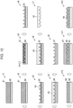
- FIG. 12 is a diagram for explaining an example of a method of manufacturing a microlens array of an embodiment. The following describes manufacturing steps for the microlens array 1A of Embodiment 1. The same or similar manufacturing steps can be applied to the microlens arrays 1B to 1H of Embodiments 2 to 8.
- the manufacturing steps for the microlens array 1A include master-pattern production steps (J1 to J4) for producing a master pattern, electroforming-mold production steps (J5 to J7) for producing an electroforming mold, secondary-mold production steps (J8 and J9) for producing a secondary mold, and imprint steps (J10 to J12) for molding a resin on a glass substrate.
- a resist resin 81 is applied to a transfer substrate 80 (step J1), and a pretreatment (for example, baking or the like) is performed on it (step J2). After that, gray-scale exposure is performed on the resist resin 81 by laser lithography (step J3). Then, after the exposure, a development treatment is performed (step J4) so that a master pattern 82 is produced.
- the cavities of the master pattern 82 have the shapes of the lens portions of the microlens array 1A.
- the depth of the resist resin 81 that can be exposed to light has a limit value (for example, 15 ⁇ m to 50 ⁇ m).
- the depth of the portion corresponding to the vertex of the first lens 11 in the resist resin 81 is deeper than or equal to the limit value. This makes it difficult to expose the portions of the resist resin 81 corresponding to the vertices portion of the first lenses 11 to light.
- the microlens array 1A includes second lenses 12, there are no or less valleys the depths of which exceed the limit, which makes it easy to produce the master pattern 82 having required shapes.
- a conductive film 83 is formed on the surface of the master pattern 82 by sputtering or the like (step J5), a conductor 84 composed of Ni (nickel) or the like on which the shape of the master pattern 82 is transferred is formed by electroplating (step J6), and the conductor 84 is released and polished (step J7), so that an electroforming mold 85 is formed.
- thermo imprinting is performed on a thermoplastic resin film 86 by using the electroforming mold 85 (step J8), and the resin film 86 is peeled off the electroforming mold 85 (step J9), so that a secondary mold 87 composed of a resin material is produced.
- a ultraviolet curing transparent resin 89 is applied to a glass substrate 88, (step J10). Then, the secondary mold 87 is brought into contact with the transparent resin 89 on the glass substrate 88, and the transparent resin 89 is cured by ultraviolet irradiation or the like (step J11). The cured transparent resin 89 is released (step J12), so that an intermediate product 90 of the microlens array 1A is produced. After that, the intermediate product 90 is subjected to characteristics evaluation, cutting with a dicing machine, an outer appearance inspection, and the like, and the microlens array 1A is thus produced.
- FIG. 13 is a diagram illustrating a light-emitting device and a sensor module according to an embodiment of the present disclosure.
- the light-emitting device 50 of the present embodiment includes a light-emitting element 51 and the microlens array 1A of Embodiment 1, which is located in the path of the light emitted by the light-emitting element 51.
- the microlens array 1A may be replaced with any of the microlens arrays 1B to 1H of Embodiments 2 to 8.
- the lens surface of the microlens array 1A (specifically, the side of the vertices of the first lenses 11 and the second lenses 12) may face the light-emitting element 51.
- the light-emitting element 51 outputs laser light
- the light-emitting element 51 may be configured to emit non-laser light.
- the light-emitting element 51 may be housed in a package 52 having a cavity structure, and the microlens array 1A may be joined to the package 52.
- the microlens array 1A may also serve as a lid of the package 52.
- the light-emitting device 50 includes the microlens array 1A of the embodiment, the light-emitting device 50 can output favorable diffused light with less interference fringes. In addition, a configuration that output favorable diffused light over a wide angle is also possible.
- the sensor module 100 of the present embodiment includes the light-emitting device 50 configured to output diffused light and a light-reception device 60 configured to receive light emitted by light-emitting device 50.
- the light-reception device 60 may be configured to receive direct light or reflected light of light emitted by the light-emitting device 50.
- the sensor module 100 may have a configuration that performs any detection such as a LiDAR (light detection and ranging) or a photoelectric sensor that detects whether an object is present in the light path.
- the light-emitting device 50 and the light-reception device 60 may be mounted on one module substrate 70 or separate module substrates.
- the light-reception device 60 includes a light-reception element 61 such as a photodiode.
- the light-reception device 60 may include lenses 62 configured to collect incident light onto the light-reception element 61 and a filter element 63 configured to narrow the wavelengths of the incident light.
- the light-reception element 61 may be housed in a package 64, and the lenses 62 and the filter element 63 may be supported by the package 64.
- the sensor module 100 of the present embodiment includes the microlens array 1A of an embodiment, the sensor module 100 can perform detection using favorable diffused light. In addition, detection using favorable diffused light over a wide angle can also be performed.
- the light-emitting device 50 of the present embodiment may have a configuration that outputs diffused light on a purpose other than detection.
- microlens array, light-emitting device, and sensor module of the present disclosure are not limited to the embodiments described above.
- the microlens arrays according to the embodiments have been described with reference to the drawings in which the vertex heights, sizes, and lens shapes of the of the multiple first lenses 11 are the same in the above embodiments, the vertex heights, sizes, and lens shapes of the multiple first lenses 11 may have variations.
- microlenses including first lenses 11 and second lenses 12 as multiple lenses 10 have been described in the above embodiments, the multiple lenses 10 may include a third lens different from the first lenses 11 and the second lenses 12.
- details described in the embodiments may be changed as appropriate within a range not departing from the spirit of the invention.
- the present disclosure is applicable to a microlens array, a light-emitting device, and a sensor module.
Landscapes
- Physics & Mathematics (AREA)
- General Physics & Mathematics (AREA)
- Optics & Photonics (AREA)
- Lenses (AREA)
- Solid State Image Pick-Up Elements (AREA)
Abstract
Description
- The present disclosure relates to a microlens array, a light-emitting device, and a sensor module.
-
Japanese Unexamined Patent Application Publication No. 2003-4907 - In the present disclosure, a microlens array includes:
- multiple first lenses having vertex heights higher than or equal to a first vertex height; and
- a second lens having a vertex height lower than the first vertex height,
- the microlens array includes:
- a first region in which a vertex distance between two first lenses, of the multiple first lenses, aligned in a first direction is smaller than a threshold in plan view; and
- a second region in which a vertex distance between two first lenses, of the multiple first lenses, aligned in the first direction is larger than the threshold in plan view, and
- the second lens is located between the two first lenses in the second region.
- In the present disclosure, a light-emitting device includes:
- a light-emitting element; and
- the microlens array mentioned above, located in a path of light emitted by the light-emitting element.
- In the present disclosure, a sensor module includes:
- the light-emitting device mentioned above; and
- a light-reception device configured to receive light emitted by the light-emitting device.
-
-
FIG. 1A is a vertical cross-sectional view of a microlens array according to an embodiment of the present invention. -
FIG. 1B is a plan view of the microlens array according to the embodiment of the present invention. -
FIG. 2 is a diagram for explaining a region where a second lens is located in the microlens array ofEmbodiment 1. -
FIG. 3 is a diagram for explaining the vertex heights of second lenses of a microlens array ofEmbodiment 2. -
FIG. 4 is a plan view of a microlens array in which first lenses are imaginarily arranged in a regular manner without changing the average value of vertex densities. -
FIG. 5 is a diagram for explaining the vertex heights of second lenses of a microlens array of Embodiment 3. -
FIG. 6 is a diagram for explaining the vertex heights of second lenses of a microlens array of Embodiment 4. -
FIG. 7 is a diagram for explaining the vertex heights of second lenses of a microlens array of Embodiment 5. -
FIG. 8 is a diagram for explaining a second lens in a microlens array of Embodiment 6. -
FIG. 9 is a diagram illustrating the light distribution characteristics of a first lens and a second lens in Embodiment 6. -
FIG. 10 is a diagram for explaining a lens arrangement in the directions parallel to the plane of a microlens array of Embodiment 7. -
FIG. 11 is a diagram for explaining a lens arrangement in the directions parallel to the plane of a microlens array of Embodiment 8. -
FIG. 12 is a diagram for explaining an example of a method of manufacturing a microlens array of an embodiment. -
FIG. 13 is a diagram illustrating a light-emitting device and a sensor module according to an embodiment of the present disclosure. - Hereinafter, embodiments of the present disclosure will be described in detail with reference to the drawings.
-
FIG. 1A is a vertical cross-sectional view of a microlens array according to an embodiment of the present invention.FIG. 1B is a plan view of the microlens array.FIG. 1A illustrates a cross section taken along line A-A inFIG. 1B . - As illustrated in
FIGs. 1A and 1B , themicrolens array 1A ofEmbodiment 1 includesmultiple lenses 10. Eachlens 10 may be a convex lens including a vertex on its one side. Themultiple lenses 10 may be arranged parallel with a plane S1 (a flat plane inFIG. 1A ) in two-dimensional directions, and eachlens 10 may have the optical axis (in other words, the main axis) in the direction normal to the plane S1. Themultiple lenses 10 may be connected with one another on the plane S1 side. Themultiple lenses 10 may have a unitary structure, which is integrally molded. Themicrolens array 1A may include atransparent substrate 2 such as a glass substrate so that themultiple lenses 10 are located on thetransparent substrate 2. - In this configuration, if light enters the
microlens array 1A from its one side (specifically, the side on which the vertices of thelenses 10 are located in the Z direction), the light is refracted by themultiple lenses 10, and diffused light can be emitted from the other face of themicrolens array 1A. -
FIG. 2 is a diagram for explaining a region where a second lens is located in the microlens array ofEmbodiment 1. - In the following, the height from a certain reference plane to the vertex of a lens is referred to as "vertex height". The reference plane may be any plane parallel to the plane S1 on which the
multiple lenses 10 are arrayed. As for eachlens 10, a range in which a lens's curved surface (for example, a convex curved surface) continues is regarded as onelens 10. In other words, a peripheral edge at which a lens curved surface has a sharp change, for example, a valley at which a lens curved surface intersects anotheradjacent lens 10, denotes a boundary of onelens 10. In another case, a bend portion at which a lens curved surface intersects a surface other than a lens curved surface (for example, a flat surface or the like) denotes a boundary of onelens 10. The bend portion mentioned above does not refer to a bend portion in a strict sense and is a concept including a bend portion including small roundness. The length in the optical axis direction from the lowermost end of the boundaries of onelens 10 to the uppermost end of the lens 10 (which, for example, if thelens 10 has a vertex, refers to the vertex) is referred to as "the vertical dimension of the lens". - The
multiple lenses 10 may include multiplefirst lenses 11 having vertex heights higher than or equal to a first vertex height H1 (seeFIG. 2 ) and one or moresecond lenses 12 having vertex heights lower than the first vertex height H1 (seeFIGs. 1A and 1B ). - The
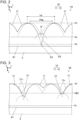
first lenses 11 and thesecond lenses 12 may have distinct differences in vertex heights. Specifically, the maximum value of the vertical dimensions of the one or moresecond lenses 12 may be smaller than or equal to the minimum value of the vertical dimensions of the multiplefirst lenses 11. The multiplefirst lenses 11 may have variations in vertex heights. - The multiple
first lenses 11 may have the first vertex height H1 as illustrated inFIG. 2 . Specifically, the vertex heights of thefirst lenses 11 may be in agreement with the first vertex height H1. The word "agreement" denotes not only "agreement in a strict sense" but is a concept including cases in which the variations are within a specified error. The range of the error in this context may be a range from the first vertex height H1 to (the first vertex height H1 + 15% of the reference vertical dimension (described later) of the first lenses 11). This configuration enablesfirst lenses 11 having the same or similar vertex heights to be located in multiple regions of themicrolens array 1A and hence enables the multiple regions to have the same or similar light distribution characteristics by thefirst lenses 11. - The multiple
first lenses 11 may have the same size and the same lens shape. This configuration makes it more likely for the multiple regions of themicrolens array 1A to have the same or similar light distribution characteristics. The words "the same size and the same lens shape" denote not only "agreement in a strict sense" but is a concept including cases in which the variations are within a specified error. The error denotes that the maximum difference in the sag of each point is within 15% of the reference vertical dimension (described later) of thefirst lenses 11 as compared with that of the curved surface of one lens. Even if the boundary positions of lens curved surfaces are different, if the shapes in the boundaries are the same, the shapes of the curved surfaces can be regarded as being the same. - As illustrated in
FIG. 1B , as for the vertex distance Lp of twofirst lenses 11 aligned in a first direction (for example, the Y direction) in plan view, themicrolens array 1A may include a first region R1 in which the vertex distance Lp is smaller than a threshold THp and a second region R2 in which the vertex distance Lp is larger than the threshold THp. This configuration causes variations in the vertex distances of thefirst lenses 11. Hence, this configuration reduces the effect that light beams having passed through the multiplefirst lenses 11 are overlayed regularly and cause interference fringes, and provides favorable light distribution characteristics. The words "plan view" denote viewing in the direction orthogonal to the plane S1. - As illustrated in
FIG. 1B , as for the vertex distance of twofirst lenses 11 aligned in a second direction (for example, the X direction) different from the first direction in plan view, themicrolens array 1A may include a third region R3 in which the vertex distance is smaller than the threshold THp and a fourth region R4 in which the vertex distance is larger than the threshold THp. Also this configuration causes variations in the vertex distances of thefirst lenses 11. Hence, this configuration reduces the effect that light beams having passed through the multiplefirst lenses 11 are overlayed regularly and cause interference fringes, and provides favorable light distribution characteristics. - A
second lens 12 may be located between twofirst lenses 11 in a second region R2 in which the vertex distance is larger than the threshold THp. Asecond lens 12 may be located between multiplefirst lenses 11 in a region where the second region R2 and fourth region R4 in which the vertex distance is larger than the threshold THp overlap each other. - As illustrated in
FIG. 2 , the threshold THp mentioned above may be set to be smaller than or equal to a vertex distance corresponding to a depth Hx, which is the depth of the valley between two adjacentfirst lenses 11, and at which a molding difficult portion D1 of lens curved surfaces appears. The vertex distance corresponding to the depth Hx refers to the distance of vertices the valley between which reaches the depth Hx. This setting provides favorable light distribution characteristics. This is because if asecond lens 12 is not present in the second region R2, the fourth region R4, or the like where the distance between adjacentfirst lenses 11 is large, the valley there is deep. Hence, molding lens curved surfaces is difficult in many valleys. In contrast, if asecond lens 12 is present between multiplefirst lenses 11 in the second region R2 or the fourth region R4, it reduces deep valleys where molding lens curved surfaces is difficult. This makes it easier to form required lens curved surfaces and makes it possible to provide themicrolens array 1A with favorable light distribution characteristics. - Alternatively, as illustrated in
FIG. 2 , the threshold THp mentioned above may be set to be smaller than or equal to a vertex distance corresponding to a depth Hy, which is the depth of the valley between two adjacentfirst lenses 11, and at which a bottom portion D2 which is out of the requirement for thefirst lens 11 appears. The vertex distance corresponding to the depth Hy refers to the distance of vertices the valley between which reaches the depth Hy. The lens shape of thefirst lens 11 is designed so as to provide required light distribution characteristics. However, this lens shape corresponds to the lens shape having a width smaller than or equal to a specified width of thefirst lens 11. If light passes through the bottom portion D2 out of the specified width, there is a possibility that the light can deviate from the required light distribution characteristics. Hence, the above setting reducesfirst lenses 11 including the bottom portion D2 and makes it possible to provide favorable light distribution characteristics. - The configuration described above also provides an advantage that makes it easier to achieve light distribution characteristics having a wide diffusion angle. If
second lenses 12 are not present, it limits the aspect ratio (specifically, the vertical dimension/the horizontal dimension) of thefirst lens 11 to reduce deep valleys where molding lens curved surfaces is difficult. However, the presence ofsecond lenses 12 mitigates the limitation to the aspect ratio of thefirst lens 11, making it possible to increase the aspect ratio of thefirst lens 11. This makes it easier to achieve light distribution characteristics having a wide diffusion angle. - As described earlier, the
second lenses 12 may have vertex heights lower than the vertex heights of thefirst lenses 11. This configuration makes the ratio of the area where thesecond lenses 12 occupy in themicrolens array 1A smaller than the ratio of the area where thefirst lenses 11 occupy in themicrolens array 1A. Accordingly, in the light diffusion effect of themicrolens array 1A, the ratio of the light diffusion effect caused by thesecond lenses 12 is smaller than the ratio of the light diffusion effect caused by the multiplefirst lenses 11. This reduces deviations of the light distribution characteristics of themicrolens array 1A from the required characteristics, caused by thesecond lenses 12. - A
second lens 12 may be located such that its vertex appears between multiplefirst lenses 11 or such that a lens curved surface not including its vertex appears between multiplefirst lenses 11. - If a pass-through region Rc (see
FIG. 13 ) is set in themicrolens array 1A, all of the outer periphery of eachlens 10 may be in contact with anotheradjacent lens 10 in at least the pass-through region Rc. The pass-through region Rc may be specified in, for example, a specification or the like as a region that light passes through. In this configuration, since surfaces (for example, flat surfaces) other than lens curved surfaces are not present in the boundaries between thelenses 10 in the pass-through region Rc, more favorable light distribution characteristics can be achieved. - Note that in the
microlens array 1A ofEmbodiment 1, themultiple lenses 10 may include a third lens (for example, a convex lens) different from thefirst lenses 11 and thesecond lenses 12. Asecond lens 12 need not be located all of the second and fourth regions R2 and R4 in which the vertex distance is large. In the second and fourth regions R2 and R4 in which the vertex distance is large, the higher the rate of asecond lens 12 being present, the higher the effect ofsecond lenses 12. -
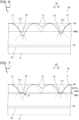
FIG. 3 is a diagram for explaining the vertex heights of second lenses of a microlens array ofEmbodiment 2. In themicrolens array 1B ofEmbodiment 2, the vertex heights of thesecond lenses 12 differ from those inEmbodiment 1, and other constituents are the same as or similar to those inEmbodiment 1. Detailed description of the same or similar constituents is omitted.FIG. 4 is a plan view of a microlens array in which first lenses are imaginarily arranged in a regular manner without changing the average value of vertex densities. - A description will be given of a case in which the multiple first lenses 11 (see
FIG. 1B ) are imaginarily arranged in a regular manner without changing the average value of vertex densities.FIGs. 3 and4 illustratefirst lenses 11 before regular arrangement andfirst lenses 11v after regular arrangement with different symbols. A regular arrangement denotes that the vertices of multiplefirst lenses 11 are arranged in a regular manner in plan view. In a regular arrangement, the vertex heights of the multiplefirst lenses 11 may be the same. A regular arrangement denotes an arrangement in which the multiple first lenses 11are arranged in a lattice shape as illustrated inFIG. 4 . Alternatively, a regular arrangement may be an arrangement in which thefirst lenses 11 are arranged in a hexagonal lattice shape. An arrangement in a hexagonal lattice shape denotes an arrangement in which multiple regular hexagons are laid out without a gap in between (in other words, an arrangement in which each side of a regular hexagon is a boundary of a pair of adjacent first lenses 11). The curved surface of the lens surface of each of the multiplefirst lenses 11v in a regular arrangement is continuous up to a boundary line B (seeFIG. 4 ) with the adjacentfirst lenses 11v. Before regular arrangement (seeFIG. 1B ), the boundaries between the multiplefirst lenses 11 have variations in height such as high positions and low positions, and the lengths of bottoms are different. Hence, if thefirst lenses 11 are imaginarily arranged in a regular manner, parts of the bottoms offirst lenses 11 that are exposed to the outside before regular arrangement are hidden in some cases, and parts of the bottoms offirst lenses 11 that are not exposed to the outside before regular arrangement are exposed to the outside in the other cases. As for parts of bottoms newly exposed, the parts of the bottoms need only to be reconfigured such that these lenses have the same or similar shapes as otherfirst lenses 11 large ranges of which were exposed to the outside also before regular arrangement. InFIG. 4 , a vertex P0, a boundary line B, the highest point P1 in the boundary line B, and the lowest point P2 in the boundary line B are indicated only for onefirst lens 11v out of the multiplefirst lenses 11v imaginarily arranged in a regular manner. InFIG. 3 , thefirst lenses 11v depicted with dashed double-dotted lines show an example of those imaginarily arranged in a regular manner. - As illustrated in
FIG. 3 , thesecond lenses 12 inEmbodiment 2 may have vertex heights lower than or equal to a first boundary height HB1. The first boundary height HB1 denotes the height of the lowest point P1 (seeFIG. 4 ) in the boundary of a pair of adjacentfirst lenses 11 if the multiplefirst lenses 11 are imaginarily arranged in a regular manner without changing the average value of vertex densities. - In plan view of the
microlens array 1B, this configuration makes the ratio of the area of the one or moresecond lenses 12 much lower than the ratio of the area of the multiplefirst lenses 11. Accordingly, in the light diffusion effect of themicrolens array 1A, the ratio of the diffusion effect caused by thesecond lenses 12 is much smaller than the ratio of the light diffusion effect caused by the multiplefirst lenses 11. This reduces deviations of the light distribution characteristics of themicrolens array 1B from the required characteristics, caused by thesecond lenses 12. - The vertex heights of the multiple
second lenses 12 need not be the same. The vertex heights of thesecond lenses 12 may be lower than the first boundary height HB1 and higher than the height Hx from which molding lens curved surfaces is difficult. -
FIG. 5 is a diagram for explaining the vertex heights of second lenses of a microlens array of Embodiment 3. In the microlens array 1C of Embodiment 3, the vertex heights of thesecond lenses 12 differ from those inEmbodiment 1, and other constituents are the same as or similar to those inEmbodiment 1. Detailed description of the same or similar constituents is omitted. - The vertex height H2 of each
second lens 12 according to Embodiment 3 satisfies the following condition.
- Here, HB1 represents the first boundary height explained in
Embodiment 2. The symbol ΔH1v represents "the reference vertical dimension" of thefirst lenses 11 which denotes the vertical dimension of thefirst lenses 11v if the multiplefirst lenses 11 are imaginarily arranged in a regular manner without changing the average value of vertex densities. - This configuration provides the following advantageous effect in addition to the same or similar one in
Embodiment 2. Specifically, the vertical dimensions offirst lenses 11 adjacent to asecond lens 12 are close to the vertical dimension ΔH1v of the imaginaryfirst lenses 11v. Hence, the ratio of the bottom lens surfaces j 1 (in other words, lens surfacesj 1 with steep slopes), which are not included in the imaginaryfirst lenses 11v, can be low. The lens curved surfaces of imaginaryfirst lenses 11v are designed in some cases to provide required light distribution characteristics, and hence there is a possibility that the lens surfacesj 1 with steep slopes located on the bottom side relative to the imaginaryfirst lenses 11v can cause light distribution characteristics to deviate from the required characteristics. To address such a case, the ratio of the lens surfacesj 1 mentioned above is low in the microlens array 1C of Embodiment 3, and thus the microlens array 1C of Embodiment 3 provides favorable light distribution characteristics. -
FIG. 6 is a diagram for explaining the vertex heights of second lenses of a microlens array of Embodiment 4. In themicrolens array 1D of Embodiment 4, the vertex heights of thesecond lenses 12 differ from those inEmbodiment 1, and other constituents are the same as or similar to those inEmbodiment 1. Detailed description of the same or similar constituents is omitted. - In Embodiment 4, the
second lenses 12 may have vertex heights lower than or equal to a second boundary height HB2. The second boundary height HB2 denotes the height of the highest point P2 in the boundary of a pair of adjacentfirst lenses 11v if the multiplefirst lenses 11 are imaginarily arranged in a regular manner without changing the average value of vertex densities. - In plan view of the
microlens array 1D, this configuration makes the ratio of the area of the one or moresecond lenses 12 much lower than the ratio of the area of the multiplefirst lenses 11. Accordingly, in the light diffusion effect of themicrolens array 1A, the ratio of the diffusion effect caused by thesecond lenses 12 is much lower the ratio of the diffusion effect caused by the multiplefirst lenses 11. This reduces deviations of the light distribution characteristics of themicrolens array 1D from the required characteristics, caused by thesecond lenses 12. - The vertex heights of the multiple
second lenses 12 need not be the same. The vertex heights of thesecond lenses 12 may be lower than the second boundary height HB2 and higher than the height Hx from which molding lens curved surfaces is difficult. -
FIG. 7 is a diagram for explaining the vertex heights of second lenses of a microlens array of Embodiment 5. In themicrolens array 1E of Embodiment 5, the vertex heights of thesecond lenses 12 differ from those inEmbodiment 1, and other constituents are the same as or similar to those inEmbodiment 1. Detailed description of the same or similar constituents is omitted. - The vertex height H2 of each
second lens 12 according to Embodiment 5 satisfies the following condition.
- Here, HB2 is the second boundary height HB2 explained in Embodiment 4. The symbol ΔH1v represents "the reference vertical dimension" of the
first lenses 11 explained in Embodiment 3. - This configuration provides the following advantageous effect in addition to the same or similar one in Embodiment 4. Specifically, the vertical dimensions of
first lenses 11 adjacent to asecond lens 12 are close to the vertical dimension ΔH1v of the imaginaryfirst lenses 11v. Hence, the ratio of the bottom lens surfaces j 1 (in other words, lens surfacesj 1 with steep slopes), which are not included in the imaginaryfirst lenses 11v, can be low. The lens curved surfaces of imaginaryfirst lenses 11v are designed in some cases to provide required light distribution characteristics, and hence there is a possibility that the lens surfacesj 1 with steep slopes located on the bottom side relative to the imaginaryfirst lenses 11v can cause light distribution characteristics to deviate from the required characteristics. To address such a case, the ratio of the lens surfacesj 1 mentioned above is low in themicrolens array 1E of Embodiment 5, and thus themicrolens array 1E of Embodiment 5 provides favorable light distribution characteristics. -
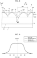
FIG. 8 is a diagram for explaining the second lenses of a microlens array of Embodiment 6.FIG. 9 is a diagram illustrating the light distribution characteristics of the first lens and the second lens in Embodiment 6. In themicrolens array 1F of Embodiment 6, the lens shape and size of thesecond lens 12 differ from those in Embodiment 3 or Embodiment 5, and the other constituents are the same as or similar to those of Embodiment 3 or Embodiment 5. Detailed description of the same or similar constituents is omitted. - The
second lenses 12 have vertex heights explained in Embodiment 3 or Embodiment 5. - The lens shapes of the
second lenses 12 of Embodiment 6 may be similar to the lens shapes of thefirst lenses 11. With this configuration, the light distribution characteristics of the light having passed through thesecond lens 12 are close to the light distribution characteristics of the light having passed through thefirst lens 11. Hence, the required light distribution characteristics are achieved by the multiplefirst lenses 11, and in addition, the light having passed through thesecond lenses 12 also has characteristics close to the required light distribution characteristics mentioned above. Thus, this configuration provides favorable light distribution characteristics. - A reference width W2v of the
second lens 12 may be twice the average value of the positional deviations ΔP of the vertex positions of thefirst lenses 11, with a tolerance of ±30%. - The reference width W2v of the
second lens 12 denotes the length of the portion of asecond lens 12 having a shape similar to that of thefirst lens 11, corresponding to a reference width W1v of thefirst lens 11. Specifically, the reference width W2v of thesecond lens 12 corresponds to (the reference width W1v of the first lens 11) × (the similarity ratio of thesecond lens 12 to the first lens 11). - The reference width W1v of the
first lens 11 denotes, if the multiplefirst lenses 11v are imaginarily arranged in a regular manner without changing the average value of vertex densities, the largest width of the boundary line B (seeFIG. 4 ) of onefirst lens 11v in a regular arrangement. - The positional deviation ΔP of the vertex position of the
first lens 11 denotes the distance between the vertex position of thefirst lens 11v after the regular arrangement mentioned above and the vertex position of thefirst lens 11 before the regular arrangement. It is assumed here that the positional deviations ΔP mentioned above are totalized in the state in which the multiplefirst lenses 11v after the regular arrangement are overlaid on the multiplefirst lenses 11 before the regular arrangement such that the total amount of the positional deviations ΔP is smallest. Although inFIG. 8 , the positional deviation ΔP is indicated as if it were a displacement in the Y direction, the positional deviation ΔP denotes the distance between two points in the X-Y plane including a displacement in the X direction. - The average value of the positional deviations ΔP may denote the average value across all of the
first lenses 11 included in themicrolens array 1F, or if a pass-through region Rc (seeFIG. 13 ) is defined, the average value of the positional deviations ΔP may denote the average value across all of thefirst lenses 11 included in the pass-through region Rc. A ± B% denotes a range of A × (100 - B)% to A × (100 + B)%. - The configuration described above provides the following advantageous effect. If the multiple
first lenses 11 are arranged so as to have positional variations with respect to those in a regular arrangement in order to reduce interference fringes, the distance between the vertices of two adjacentfirst lenses 11 is also varied. If thefirst lenses 11 have the variations mentioned above, the value of a positional deviation of the vertex position of afirst lens 11 that occurs frequently is close to the average value of the positional deviations. Hence, the value of a vertex distance that occurs frequently in a region where the vertex distance of two adjacentfirst lenses 11 becomes larger than in the regular arrangement is close to the value twice the average value of the positional deviations. - If a
second lens 12 is located between twofirst lenses 11 having a vertex distance twice the average value of the positional deviations, and the reference width W2v of thesecond lens 12 is close to twice the average value of the positional deviations mentioned above, the vertex of thesecond lens 12 is exposed to the outside from the height close to the reference width W2v as illustrated inFIG. 8 . In other words, if the reference width W2v of thesecond lens 12 is the length mentioned above, the vertices of manysecond lenses 12 are exposed to the outside from the height close to the reference width W2v. - As illustrated in
FIG. 9 , the light distribution characteristics of a first lens 11 a portion of which on the vertex side of the reference width W1v is exposed to the outside and the light distribution characteristics of a second lens 12 a portion of which on the vertex side of the reference width W2v is exposed to the outside approximate each other because thefirst lens 11 and thesecond lens 12 have similar lens shapes. - Hence, in the
microlens array 1F of Embodiment 6, many of the multiplesecond lenses 12 have light distribution characteristics that approximate the light distribution characteristics of thefirst lens 11. Thus themicrolens array 1F of Embodiment 6 provides favorable light distribution characteristics. -
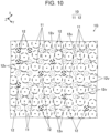
FIG. 10 is a diagram for explaining a lens arrangement in the directions parallel to the plane of a microlens array of Embodiment 7. InFIG. 10 , thefirst lenses 11 are indicated by dashed line circles, and thesecond lenses 12 are indicated by bold dashed line circles. A dashed line circle represents the outer periphery of afirst lens 11 approximately at half of its height. A bold dashed line circle represents the outer periphery of asecond lens 12 approximately at half of its height. If the outer periphery of asecond lens 12 indicated by a bold dashed line circle overlapsfirst lenses 11, it may not be exposed to the outside in some cases. InFIG. 10 , dashed double-dotted line circles indicate imaginary lens surfaces that do not appear as lens surfaces and are referred to as imaginarysecond lenses 12v. The center point of each circle indicates the vertex of a lens. - In the
microlens array 1G of Embodiment 7, the multiplefirst lenses 11 may be located in an irregular manner in plan view, and in contrast, the multiplesecond lenses 12 may be located in a regular manner in plan view. - The words "being located in a regular manner" denote a state in which a grid can be determined such that each one of the multiple
second lenses 12 is located in a different cell of the grid. In the example ofFIG. 10 , a grid in which each grid cell surrounds one of the multiplesecond lenses 12 or the imaginary multiplesecond lenses 12v can be determined. The grid cells of this grid may have the same size as those of the grid for the multiplefirst lenses 11 rearranged such that their vertices are located in a regular manner without changing the average value of vertex densities. - This configuration provides an advantage that the arrangement of the
second lenses 12 can be easily designed when themicrolens array 1G is designed. Specifically, the designer first determines the locations of the multiplefirst lenses 11 and the multiplesecond lenses 12 such that thefirst lenses 11 and thesecond lenses 12 are arranged in a regular manner. After that, the vertex positions of the multiplefirst lenses 11 are shifted from the regular arrangement so as to be arranged in an irregular manner. Thus, themicrolens array 1G of Embodiment 7 can be designed such that asecond lens 12 does not appear in a valley between two adjacentfirst lenses 11 that is higher than thesecond lens 12, and asecond lens 12 appears in a valley between two adjacentfirst lenses 11 that is lower than thesecond lens 12. -
FIG. 11 is a diagram for explaining a lens arrangement in the directions parallel to the plane of a microlens array of Embodiment 8. - In the
microlens array 1H of Embodiment 8, in plan view, the multiplefirst lenses 11 may be located in an irregular manner, and eachsecond lens 12 may be located at the center of a polygon plg formed by connecting the vertices of the surrounding multiplefirst lenses 11. - The words "the
first lenses 11 surrounding asecond lens 12" may denote the multiplefirst lenses 11 that are in contact with thesecond lens 12 or may denote nfirst lenses 11 that are closest to thesecond lens 12. The number n may be four if the arrangement of the multiplefirst lenses 11 is close to a square grid and may be six if the arrangement of the multiplefirst lenses 11 is close to a hexagonal grid. - The center of a polygon plg may denote the center of gravity of a polygon plg. The center of gravity denotes the position of the center of gravity if a polygon plg is assumed to be a plane having a uniform weight density, which means (the sum total of the position vectors from a reference point to all of the vertices of the polygon plg)/(the number of vertices).
- Alternatively, the center of a polygon plg may be a point at which the difference in the distance from the point to each vertex of the polygon plg is smallest or may be the midpoint of the longest one of the diagonal lines of the polygon plg.
- The center of a polygon plg is not limited to the points in agreement with the points defined as above in a strict sense and may be a point located within a range including an error of a tolerance or so around the point mentioned above.
- This configuration increases the ratio of the number of the
second lenses 12 the vertices of which appear to the number of the multiple second lenses. This reduces an imbalance of light distribution of the light having passed through the multiplesecond lenses 12 and enables themicrolens array 1H to provide more favorable light distribution characteristics. -
FIG. 12 is a diagram for explaining an example of a method of manufacturing a microlens array of an embodiment. The following describes manufacturing steps for themicrolens array 1A ofEmbodiment 1. The same or similar manufacturing steps can be applied to themicrolens arrays 1B to 1H ofEmbodiments 2 to 8. - The manufacturing steps for the
microlens array 1A include master-pattern production steps (J1 to J4) for producing a master pattern, electroforming-mold production steps (J5 to J7) for producing an electroforming mold, secondary-mold production steps (J8 and J9) for producing a secondary mold, and imprint steps (J10 to J12) for molding a resin on a glass substrate. - In the master-pattern production steps, a resist resin 81 is applied to a transfer substrate 80 (step J1), and a pretreatment (for example, baking or the like) is performed on it (step J2). After that, gray-scale exposure is performed on the resist resin 81 by laser lithography (step J3). Then, after the exposure, a development treatment is performed (step J4) so that a
master pattern 82 is produced. The cavities of themaster pattern 82 have the shapes of the lens portions of themicrolens array 1A. In the step J3 in which the portions of the resist resin 81to be removed are exposed to light, the depth of the resist resin 81 that can be exposed to light has a limit value (for example, 15 µm to 50 µm). Hence, if a valley betweenfirst lenses 11 has a depth deeper than or equal to the limit value, the depth of the portion corresponding to the vertex of thefirst lens 11 in the resist resin 81 is deeper than or equal to the limit value. This makes it difficult to expose the portions of the resist resin 81 corresponding to the vertices portion of thefirst lenses 11 to light. However, since themicrolens array 1A includessecond lenses 12, there are no or less valleys the depths of which exceed the limit, which makes it easy to produce themaster pattern 82 having required shapes. - In the electroforming-mold production steps, a
conductive film 83 is formed on the surface of themaster pattern 82 by sputtering or the like (step J5), aconductor 84 composed of Ni (nickel) or the like on which the shape of themaster pattern 82 is transferred is formed by electroplating (step J6), and theconductor 84 is released and polished (step J7), so that anelectroforming mold 85 is formed. - In the secondary-mold production steps, thermal imprinting is performed on a
thermoplastic resin film 86 by using the electroforming mold 85 (step J8), and theresin film 86 is peeled off the electroforming mold 85 (step J9), so that asecondary mold 87 composed of a resin material is produced. - In the imprint steps, for example, a ultraviolet curing
transparent resin 89 is applied to aglass substrate 88, (step J10). Then, thesecondary mold 87 is brought into contact with thetransparent resin 89 on theglass substrate 88, and thetransparent resin 89 is cured by ultraviolet irradiation or the like (step J11). The curedtransparent resin 89 is released (step J12), so that anintermediate product 90 of themicrolens array 1A is produced. After that, theintermediate product 90 is subjected to characteristics evaluation, cutting with a dicing machine, an outer appearance inspection, and the like, and themicrolens array 1A is thus produced. -
FIG. 13 is a diagram illustrating a light-emitting device and a sensor module according to an embodiment of the present disclosure. The light-emittingdevice 50 of the present embodiment includes a light-emittingelement 51 and themicrolens array 1A ofEmbodiment 1, which is located in the path of the light emitted by the light-emittingelement 51. Themicrolens array 1A may be replaced with any of themicrolens arrays 1B to 1H ofEmbodiments 2 to 8. The lens surface of themicrolens array 1A (specifically, the side of the vertices of thefirst lenses 11 and the second lenses 12) may face the light-emittingelement 51. Although the light-emittingelement 51 outputs laser light, the light-emittingelement 51 may be configured to emit non-laser light. The light-emittingelement 51 may be housed in apackage 52 having a cavity structure, and themicrolens array 1A may be joined to thepackage 52. Themicrolens array 1A may also serve as a lid of thepackage 52. - Since the light-emitting
device 50 includes themicrolens array 1A of the embodiment, the light-emittingdevice 50 can output favorable diffused light with less interference fringes. In addition, a configuration that output favorable diffused light over a wide angle is also possible. - As illustrated in
FIG. 13 , thesensor module 100 of the present embodiment includes the light-emittingdevice 50 configured to output diffused light and a light-reception device 60 configured to receive light emitted by light-emittingdevice 50. The light-reception device 60 may be configured to receive direct light or reflected light of light emitted by the light-emittingdevice 50. Thesensor module 100 may have a configuration that performs any detection such as a LiDAR (light detection and ranging) or a photoelectric sensor that detects whether an object is present in the light path. The light-emittingdevice 50 and the light-reception device 60 may be mounted on onemodule substrate 70 or separate module substrates. - The light-
reception device 60 includes a light-reception element 61 such as a photodiode. The light-reception device 60 may includelenses 62 configured to collect incident light onto the light-reception element 61 and afilter element 63 configured to narrow the wavelengths of the incident light. The light-reception element 61 may be housed in apackage 64, and thelenses 62 and thefilter element 63 may be supported by thepackage 64. - Since the
sensor module 100 of the present embodiment includes themicrolens array 1A of an embodiment, thesensor module 100 can perform detection using favorable diffused light. In addition, detection using favorable diffused light over a wide angle can also be performed. - Note that the light-emitting
device 50 of the present embodiment may have a configuration that outputs diffused light on a purpose other than detection. - The embodiments of the present disclosure have been described above. However, the microlens array, light-emitting device, and sensor module of the present disclosure are not limited to the embodiments described above. For example, although the microlens arrays according to the embodiments have been described with reference to the drawings in which the vertex heights, sizes, and lens shapes of the of the multiple
first lenses 11 are the same in the above embodiments, the vertex heights, sizes, and lens shapes of the multiplefirst lenses 11 may have variations. Although microlenses includingfirst lenses 11 andsecond lenses 12 asmultiple lenses 10 have been described in the above embodiments, themultiple lenses 10 may include a third lens different from thefirst lenses 11 and thesecond lenses 12. In addition, details described in the embodiments may be changed as appropriate within a range not departing from the spirit of the invention. - The present disclosure is applicable to a microlens array, a light-emitting device, and a sensor module.
-
- 1A to 1H
- microlens array
- 10
- lens
- 11
- first lens
- 11v
- first lens arranged in a regular manner
- 12
- second lens
- Lp
- vertex distance
- THp
- threshold
- R1
- first region
- R2
- second region
- R3
- third region
- R4
- fourth region
- H1
- first vertex height
- HB1
- first boundary height
- HB2
- second boundary height
- ΔH1v
- reference vertical dimension
- W1v, W2v
- reference width
- ΔP
- positional deviation
- plg
- polygon
- 50
- light-emitting device
- 51
- light-emitting element
- 60
- light-reception device
- 61
- light-reception element
- 100
- sensor module
Claims (10)
- A microlens array comprising:multiple first lenses having vertex heights higher than or equal to a first vertex height; anda second lens having a vertex height lower than the first vertex height, whereinthe microlens array includes:a first region in which a vertex distance between two first lenses, of the multiple first lenses, aligned in a first direction is smaller than a threshold in plan view; anda second region in which a vertex distance between two first lenses, of the multiple first lenses, aligned in the first direction is larger than the threshold in plan view, andthe second lens is located between the two first lenses in the second region.
- The microlens array according to claim 1, wherein
the microlens array further includes:a third region in which a vertex distance between two first lenses, of the multiple first lenses, aligned in a second direction different from the first direction is smaller than the threshold in plan view; anda fourth region in which a vertex distance between two first lenses, of the multiple first lenses, aligned in the second direction is larger than the threshold in plan view, andthe second lens is located between first lenses, of the multiple first lenses, in a region where the second region overlaps the fourth region. - The microlens array according to claim 1 or 2, whereinif the multiple first lenses are imaginarily arranged in a regular manner without changing an average value of vertex densities, and height of a lowest point in a boundary between a pair of adj acent first lenses, of the multiple first lenses, is referred to as a first boundary height,vertex height of the second lens is lower than or equal to the first boundary height.
- The microlens array according to claim 3, wherein
 where HB1 represents the first boundary height,ΔH1v represents vertical dimension of the first lenses if the first lenses are arranged in the regular manner, andH2 represents vertex height of the second lens.
 - The microlens array according to claim 1 or 2, whereinif the multiple first lenses are imaginarily arranged in a regular manner without changing an average value of vertex densities, and height of a highest point in a boundary between a pair of adj acent first lenses, of the multiple first lenses, is referred to as a second boundary height,vertex height of the second lens is lower than or equal to the second boundary height.
- The microlens array according to claim 5, wherein
 where HB2 represents the second boundary height,ΔH1v represents vertical dimension of the first lenses if the first lenses are arranged in the regular manner, andH2 represents vertex height of the second lens.
 - The microlens array according to any one of claims 1 to 6, whereinlens shape of the second lens is similar to lens shapes of the first lenses, andif the multiple first lenses are imaginarily arranged in a regular manner without changing an average value of vertex densities, a largest width of boundaries between one of the first lenses and surrounding ones of the first lenses is referred to as a reference width of the first lenses, and length of a portion, corresponding to the reference width of the first lenses, in the second lens having a shape similar to shapes of the first lenses is referred to as a reference width of the second lens,the reference width of the second lens is twice an average value of positional deviations with a tolerance of ±30%, each positional deviation being a positional deviation of one of the multiple first lenses from a state in which the multiple first lenses are arranged in the regular manner.
- The microlens array according to any one of claims 1 to 7, wherein
in plan view, a vertex of the second lens is located at a center of a polygon formed by connecting vertices of multiple first lenses, of the multiple first lenses, located around the second lens. - A light-emitting device comprising:a light-emitting element; andthe microlens array according to any one of claims 1 to 6, located in a path of light emitted by the light-emitting element.
- A sensor module comprising:the light-emitting device according to claim 9; anda light-reception device configured to receive light emitted by the light-emitting device.
Applications Claiming Priority (2)
| Application Number | Priority Date | Filing Date | Title |
|---|---|---|---|
| JP2021211351 | 2021-12-24 | ||
| PCT/JP2022/047153 WO2023120587A1 (en) | 2021-12-24 | 2022-12-21 | Microlens array, light-emitting device, and sensor module |
Publications (1)
| Publication Number | Publication Date |
|---|---|
| EP4455743A1 true EP4455743A1 (en) | 2024-10-30 |
Family
ID=86902638
Family Applications (1)
| Application Number | Title | Priority Date | Filing Date |
|---|---|---|---|
| EP22911289.1A Withdrawn EP4455743A1 (en) | 2021-12-24 | 2022-12-21 | Microlens array, light-emitting device, and sensor module |
Country Status (5)
| Country | Link |
|---|---|
| US (1) | US20240353595A1 (en) |
| EP (1) | EP4455743A1 (en) |
| JP (1) | JP7753392B2 (en) |
| CN (1) | CN118435085A (en) |
| WO (1) | WO2023120587A1 (en) |
Family Cites Families (6)
| Publication number | Priority date | Publication date | Assignee | Title |
|---|---|---|---|---|
| JP3119846B2 (en) * | 1998-09-17 | 2000-12-25 | 恵和株式会社 | Light diffusion sheet and backlight unit using the same |
| JP4845290B2 (en) | 2001-06-20 | 2011-12-28 | キヤノン株式会社 | Micro lens array, optical equipment and optical viewfinder |
| JP4603244B2 (en) | 2003-05-07 | 2010-12-22 | オリンパス株式会社 | Focus plate and method of manufacturing the focus plate |
| CN104570172A (en) * | 2014-12-11 | 2015-04-29 | 太湖金张科技股份有限公司 | Optical diffusion structure and backlight source device |
| WO2019035653A1 (en) * | 2017-08-18 | 2019-02-21 | 엘지이노텍 주식회사 | Surface emitting laser package |
| JP2023099236A (en) * | 2020-05-22 | 2023-07-12 | ソニーセミコンダクタソリューションズ株式会社 | Light-emitting device and ranging device |
-
2022
- 2022-12-21 US US18/721,798 patent/US20240353595A1/en not_active Abandoned
- 2022-12-21 JP JP2023569497A patent/JP7753392B2/en active Active
- 2022-12-21 CN CN202280083823.8A patent/CN118435085A/en active Pending
- 2022-12-21 WO PCT/JP2022/047153 patent/WO2023120587A1/en not_active Ceased
- 2022-12-21 EP EP22911289.1A patent/EP4455743A1/en not_active Withdrawn
Also Published As
| Publication number | Publication date |
|---|---|
| JP7753392B2 (en) | 2025-10-14 |
| WO2023120587A1 (en) | 2023-06-29 |
| US20240353595A1 (en) | 2024-10-24 |
| JPWO2023120587A1 (en) | 2023-06-29 |
| CN118435085A (en) | 2024-08-02 |
Similar Documents
| Publication | Publication Date | Title |
|---|---|---|
| US12313916B2 (en) | Optical apparatus with structure for liquid invariant performance | |
| JP5024047B2 (en) | Manufacturing method of microstructure | |
| KR102026005B1 (en) | Composite diffusion plate | |
| CN111527421B (en) | Concave-convex structure, optical component and electronic device | |
| WO2020201111A1 (en) | Transparent optical portion, optical device and method for manufacturing an optical device | |
| EP1542074A1 (en) | Manufacturing a replication tool, sub-master or replica | |
| US20150070870A1 (en) | Illumination system | |
| JP2011107195A (en) | Optical element, method of manufacturing the same, minutely rugged structure, and molding die | |
| US20040156112A1 (en) | Method of manufacturing microlens array | |
| US10583585B2 (en) | Method of manufacturing a screen provided with retroreflective microstructures | |
| EP4455743A1 (en) | Microlens array, light-emitting device, and sensor module | |
| CN118829906A (en) | Diffuser, light emitting device and sensor module | |
| CN102084273B (en) | Optical component having antireflective structure and method for manufacturing the optical component | |
| CN216387438U (en) | Combined micro-lens array light uniformizing structure and lens and equipment provided with same | |
| CN212658852U (en) | Reflection type diffraction element, projection film set, electro-optical device, and electronic apparatus | |
| KR20110070141A (en) | Three-dimensional sheet and its manufacturing method | |
| US8649096B2 (en) | Fine grating and mold therefor | |
| CN213648656U (en) | Lens impression mould and lens module | |
| WO2022138725A1 (en) | Diffusion plate, light-emitting device, and sensor module | |
| JP2010169751A (en) | Reflection plate and method for manufacturing mold for manufacturing reflection plate | |
| US20050016855A1 (en) | Method for manufacturing a light guide plate mold | |
| JP4798284B2 (en) | Manufacturing method of optical waveguide | |
| HK40069276A (en) | Optical apparatus with structure for liquid invariant performance |
Legal Events
| Date | Code | Title | Description |
|---|---|---|---|
| STAA | Information on the status of an ep patent application or granted ep patent |
Free format text: STATUS: THE INTERNATIONAL PUBLICATION HAS BEEN MADE |
|
| PUAI | Public reference made under article 153(3) epc to a published international application that has entered the european phase |
Free format text: ORIGINAL CODE: 0009012 |
|
| STAA | Information on the status of an ep patent application or granted ep patent |
Free format text: STATUS: REQUEST FOR EXAMINATION WAS MADE |
|
| 17P | Request for examination filed |
Effective date: 20240618 |
|
| AK | Designated contracting states |
Kind code of ref document: A1 Designated state(s): AL AT BE BG CH CY CZ DE DK EE ES FI FR GB GR HR HU IE IS IT LI LT LU LV MC ME MK MT NL NO PL PT RO RS SE SI SK SM TR |
|
| DAV | Request for validation of the european patent (deleted) | ||
| DAX | Request for extension of the european patent (deleted) | ||
| STAA | Information on the status of an ep patent application or granted ep patent |
Free format text: STATUS: THE APPLICATION HAS BEEN WITHDRAWN |
|
| 18W | Application withdrawn |
Effective date: 20250911 |