EP4455737A1 - Partikeldetektor - Google Patents
Partikeldetektor Download PDFInfo
- Publication number
- EP4455737A1 EP4455737A1 EP23169901.8A EP23169901A EP4455737A1 EP 4455737 A1 EP4455737 A1 EP 4455737A1 EP 23169901 A EP23169901 A EP 23169901A EP 4455737 A1 EP4455737 A1 EP 4455737A1
- Authority
- EP
- European Patent Office
- Prior art keywords
- detector
- collection
- particles
- stack
- photons
- Prior art date
- Legal status (The legal status is an assumption and is not a legal conclusion. Google has not performed a legal analysis and makes no representation as to the accuracy of the status listed.)
- Withdrawn
Links
Images


Classifications
-
- G—PHYSICS
- G01—MEASURING; TESTING
- G01T—MEASUREMENT OF NUCLEAR OR X-RADIATION
- G01T1/00—Measuring X-radiation, gamma radiation, corpuscular radiation, or cosmic radiation
- G01T1/16—Measuring radiation intensity
- G01T1/20—Measuring radiation intensity with scintillation detectors
-
- G—PHYSICS
- G01—MEASURING; TESTING
- G01T—MEASUREMENT OF NUCLEAR OR X-RADIATION
- G01T1/00—Measuring X-radiation, gamma radiation, corpuscular radiation, or cosmic radiation
- G01T1/16—Measuring radiation intensity
- G01T1/20—Measuring radiation intensity with scintillation detectors
- G01T1/2018—Scintillation-photodiode combinations
- G01T1/20181—Stacked detectors, e.g. for measuring energy and positional information
-
- G—PHYSICS
- G01—MEASURING; TESTING
- G01T—MEASUREMENT OF NUCLEAR OR X-RADIATION
- G01T1/00—Measuring X-radiation, gamma radiation, corpuscular radiation, or cosmic radiation
- G01T1/29—Measurement performed on radiation beams, e.g. position or section of the beam; Measurement of spatial distribution of radiation
- G01T1/2914—Measurement of spatial distribution of radiation
- G01T1/2921—Static instruments for imaging the distribution of radioactivity in one or two dimensions; Radio-isotope cameras
- G01T1/2928—Static instruments for imaging the distribution of radioactivity in one or two dimensions; Radio-isotope cameras using solid state detectors
Definitions
- the present disclosure relates to a detector stack for measuring spatial and/or spectral properties of particles impinging thereon. It also relates to a method for measuring spatial and/or spectral properties of particles impinging on the detector stack.
- detectors for spectrally and spatially characterizing particle beams there are known detectors for spectrally and spatially characterizing particle beams.
- An example thereof are RCF, Radiochromic film, detectors, which are used to detect protons.
- the films are placed one after each other and are capable of recording the spatial distribution as a function of proton energy.
- RCF detectors are difficult to use since after each measurement the RCF needs to be physically extracted from the detector, manually analyzed, and replaced after every use.
- scintillation-based detectors present a number of disadvantages. For instance, they have a physical extension whose miniaturization is limited by the need to image scintillator via the imaging system. They also have a limited energy resolution, and are subject to propagation effects as well as scattering effects.
- the present disclosure has been conceived in view of the above shortcomings. It is hence an objective of the disclosure to at least partially mitigate the shortcomings of the known art.
- a detector stack comprising a first detector and a second detector (U1, U2) arranged along a first direction.
- Each of the first detector and second detector (U1, U2) comprise generation means and collection means.
- the generation means (5a, 5b) are configured to generate photons or charged particles when interacting with incident particles, the photons or charged particles being indicative of energies of the respective incident particles.
- the collection means (7a, 7b) are configured to collect the generated photons or charged particles and output an output signal representing information of a one-dimensional travelling direction of the incident particles.
- the collection means of the first detector (7a) and the collection means of the second detector (7b) are configured to respectively output output signals representing different one-dimensional travel directions of the incident particles.
- the detector stack performs the detections by means of photons or charged particles generation and since each detector acquire information based on different travelling directions of the particles, it is possible to improve the usability of the detector stack while also ensuring high spatial resolution and real-time read of the particles.
- At least one of the first detector and second detector further comprises absorber means.
- Either the absorber means (2a, 2b), the generation means (5a, 5b) and the collection means (7a, 7b) are arranged in this order in the first direction.
- the generation means (5a, 5b) and the collection means (7a, 7b) are the same means which is embedded in the absorber means (2a, 2b).
- the absorber layer it is possible to improve the spectral resolution of the incoming particles.
- the first detector comprises a filter (6) configured to filter the incident particles along a filtering direction, the filter being arranged between the generation means and the collection means in the first direction.
- the additional filter it is possible to gather additional information regarding the origin of the scintillation source, thus increasing the spatial resolution of the detector.
- the detector stack of any one of the preceding aspects wherein the collection means (5) of the first detector (U1) includes an array of waveguides.
- wave guides as collection layer simplifies the architecture of the detector and hence increases its usability.
- the detector stack of the fourth aspect wherein the waveguides of the array are disposed substantially in parallel to define a collection direction, preferably wherein the waveguides of the array are disposed along the second direction.
- the detector stack of the fifth aspect wherein the collection means (5) of the second detector (U2) includes an array of waveguides disposed substantially in parallel to define a collection direction, wherein the collection direction of the first detector and the collection direction of the second detector are tilted one with respect to another of a first tilting angle.
- the detector stack of the sixth aspect wherein the first tilting angle is substantially a right angle.
- the detector stack of any one of the fifth to seventh aspect wherein the filtering direction of the filter of the first detector (U1) is rotated of a second tilting angle with respect to the collection direction of the first detector (U1).
- the detector of the eighth aspect wherein the second tilting angle is substantially a right angle.
- the detector stack of any one of the preceding aspects further comprising a measurement device configured to measure the output signals, wherein the measurement device is configured to perform time of flight, measurements.
- the detector stack of any one of the previous aspects comprising a plurality of detectors, each detector of the plurality of detectors comprising at least generation means and collection means, wherein, immediate neighboring detectors in the first direction are configured to respectively output output signals representing different one-dimensional travel directions of the incident particles.
- a detector stack according to any of the preceding aspects, wherein the collection means of the first detector (7a) and the collection means of the second detector (7b) are configured to respectively output output signals representing different one-dimensional travel directions of the incident particles in a plane defined by a second direction and a third direction, the first direction, the second direction and the third direction being different directions.
- the detector stack any one of the preceding aspects, wherein the generation means (5a, 5b) is a generation layer and the collection means (7a, 7b) is a collection layer, wherein the generation layer and the collection layer are layers extending along the second direction and the third direction.
- a fourteenth aspect there is provided a method for detecting energy and spatial distribution of particles by using a detector stack comprising a first detector and a second detector (U1, U2), arranged along a first direction, each of the first detector and second detector comprising generation means and collection means, the collection means of the first detector (7a) and the collection means of the second detector (7b) being configured to respectively output output signals representing different one-dimensional travel directions of the incident particles, the method comprising the steps of:
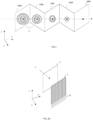
- FIG. 1 shows a RCF, Radiochromic film, detector according to the known art.
- An RCF detector is made up of a plurality of RC films, 100a to 100e and each film is capable of detecting charged particles, as for instance, protons.
- the particles impinge on a first film 100a of the plurality of films, cross it, and impinge on a next film of the stack 100b.
- a plurality of films or layers may also be referred to as stack.
- the filters may be impinged on.
- the RC film is colored, this is shown as a concentric pattern in the figure.
- RF films includes a particular dye which changes its color when exposed to certain kind of radiation. This in turn enables the level of exposure and the properties of the particles to be determined after impinging on the film.
- FIG. 1 shows five films
- known RC detectors may have a different number of films. Two consecutive films are separated by a spacing which can be for instance defined in terms of the angle between two subsequent films. For instance, the angle defined on a plane perpendicular to the planes in which the films are included.
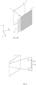
- FIG. 2A and 2B show examples of respective detector units which can be employed in the detector stack according to the first embodiment of the present disclosure.
- the detector stack is configured to detect the energy and the spatial distribution of particles impinging on the detector stack (impinging particles) .
- FIG. 2A shows a detector, or detector unit, comprising photon generation means 5 and collection means 7 arranged in this order along a first direction (x-axis).
- the photon generation means are an example of generation means.
- the photon generation means 5 may be a photon generation layer. The layer may elongate along a second direction (y-axis) and a third direction (z-axis).
- the photon generation means 5 is an example of generation means 5.
- the collection means 7 may be a collection layer. The collection layer may elongate along the second direction (y-axis) and the third direction (z-axis) and may hence be parallel to the photon generation layer 5.
- the detector is configured to detect the energy of particles and resolve their distribution spatially.
- the particles may be referred to as incident particles, impinging particles, flux of particles, flux of incident particles, particle beam or incident particle beam.
- the first direction is oriented to correspond, or partially correspond, to the travelling direction of the particles.
- the particles may have a plurality of travelling directions i.e., the plurality of travelling directions of each single particle making up the particles. Therefore, the travelling direction of the particle may be the median, i.e., the averaged, travelling direction of the particles.
- the vectorial direction of the first direction is oriented to have a non-zero component in the travelling direction of the particles. That is, along the first direction there is a positive side and a negative side defined by the travelling direction of the particles. The particles travel from the negative side to the positive side.
- the detector and the particles are mutually arranged so that the first direction corresponds, or substantially corresponds, to the travelling direction of the particles. This leads to a maximization of the detection function of the detector
- the detector may also comprise transport means 8 configured to collect and transport an output signal.
- the output signal may correspond for instance, to the photons collected by the collection means 7.
- the output signal may otherwise be indicative of the collected photons.
- the output signal may be indicative of the energy of the collected photons.
- the output signal may also be indicative of the number of the collected photons. That is, the output signal may be a signal having a functional dependency on the energy and/or number of the collected photons.
- the output signal may be an electrical signal indicative of the number of photons, generated. Based on the generated photons, the output signal may be obtained by using conventional techniques such as for instance photomultiplication.
- the transport means 8 may comprise circuitry for transporting the generated photons and/or for converting the generated photons in electric current.
- the photon generation means 5 is configured to generate photons when interacting with incident particles.
- the photon generation means 5 may for instance be a scintillation layer, or a scintillator. That is, it may be a mean or a layer, configured to generate photons via scintillation.
- the photon generation means 5 is not limited thereto. Physical processes different from scintillation and according to which a particle generates photons when impinging on a material, may also be employed.
- the impinging particles may be for instance single species particles such as electrons, protons, or neutrons but they are not limited thereto. For instance, they may also be ions, atoms, or alpha particles.
- the particles may comprise a mixture of different single-species particles. For instance, the particles may comprise a mixture of protons, neutrons, electrons, ions, atoms and/or alpha particles.
- the photons generated by the photon generation means 5 are indicative of energies of the respective incident particles.
- a particle, to impinge on, or pass through, the photon generation means 5, and/or to generate photons must have a minimum energy.
- This minimum energy depends on the detector unit physical properties and geometry as well as on the detector stack's geometry. That is, the minimum energy is known in advance. For instance, and with reference to FIG. 4 , FIG. 6 and FIG. 7 , it also depends on the presence and on the properties of the absorption layer (s) 2 to 4. That is, the fact that a particle generates photons per se, means that the particle has a minimum energy.
- Different detectors in a detector stack such as that of FIG. 5 , FIG. 6 and FIG. 7 have different minimum energies. Therefore, it becomes possible to measure the energies of the particle by establishing which minimum energy a given particle has.
- the collection means 7 is configured to collect the generated photons and output an output signal representing information of a one-dimensional travelling direction of the incident particles.
- the collection means 7 may be configured to output an output signal representing only information of a one-dimensional travelling direction of the incident particles in the plane defined by the second and third direction.
- the signal output by the collection means does not permit to derive information of a second, independent, travelling direction of the incident particles in the plane defined by the second and third direction.
- the collection means 7, may be divided in a plurality of stripes (depicted in the figures as longitudinal areas). Each stripe is configured to gather photons generated in a corresponding area of the generation means 5.
- the collection means 7 is divided in vertical stripes extending along the z-axis.
- the output signal output by the collection means 7 provides information on the photon collected along the whole z-axis of the detector. Thus, it provides information relative to the y-coordinate of a given incident particle. That is, the collection means integrates along the z-axis, or in other words, sums the signal (i.e., the photons) gathered along a single stripe.
- each of the stripes is defined along the second direction (y-axis in the figure) and along the third direction (z-axis in the figure).
- the stripes are elongated along the third direction and are configured to collect respective photons in the third direction.
- the stripes are therefore configured to provide information relative to the travelling direction of the particles along the second direction.
- the photon generation means 5 and the collection means 7 are close enough so that it can be assumed that photon generated in a portion of the photon generation means are also collected by a corresponding portion of the collection means.
- the first direction, the second direction, and the third direction are each defined by vectorial components.
- the first direction, the second direction and the third direction are different directions. That is, at least one of the vectorial components defining the first direction is different from at least one of the vectorial components defining the second direction. At least one of the vectorial components defining the first direction is different from at least one of the vectorial components defining the third direction. Moreover, at least one vectorial components defining the second direction is different from at least one vectorial components defining the third direction.
- the first direction, the second direction, and the third direction are perpendicular to each other.
- the first direction, the second direction and the third direction are represented respectively by the cartesian vectors: (1,0,0), (0,1,0), and (0,0,1) .
- a configuration in which all the stripes of the collection means 7 are arranged in parallel is preferrable since it makes it easier to perform data analysis of the output signal.
- different geometrical arrangements may be employed. In this case, the specific geometries of the strips are to be taken into account when analyzing the output signal.
- the stripes may be oblique in the plane defined by the second direction and the third direction (i.e., the y-z plane).
- the collection means 7 may be divided in different sectors. The stripes may be differently oriented in different sectors of the collection means 7.
- the direction of the stripes defines the collection direction of the collection means 7.
- the collection direction is therefore the direction along which the photons are collected, and the direction along which the signal is integrated along the stripe.
- the collection direction is different from the first direction and it is included in the plane defined by the second direction and the third direction (y-z plane).
- the collection direction may correspond, or substantially correspond, to the second direction.
- it may correspond, or substantially correspond to the third direction.
- the collection means 7 may be, or may comprise, for instance an array of waveguides.
- a given single waveguide of the array of waveguides may correspond to a given stripe of the collection means 7.
- a wave guide may be a cylindrically symmetric structure.
- it may be of a substantially parallelepiped form, e.g., it may have a substantial parallelepiped shape. This enables to maximize their collection surface and hence their collection function, while also optimizing space usage.
- the waveguides need in principle not to be all equal, to be all parallel one to another, and/or to be all of a linear or parallelepiped form. That is, they do not need to have identical, similar, or substantially similar geometrical properties.
- Example of geometrical properties may be for instance, the length of the waveguide, the cross-section of the waveguide, the form or shape of the waveguide etc..
- the waveguides may all be substantially identical or at least similar. That is, they may be characterized by substantially the same geometrical properties.
- the waveguides may be preferably linearly disposed in the array and be all parallel one to another or substantially parallel one to another.
- the collection direction of the collection means 7 is defined by the symmetry axis of a waveguides. Since the waveguides have a cylindrical symmetry, the collection direction corresponds to the axial direction of the waveguides.
- the photon generation means 5 and the collection means 7 may be the same means, i.e., a generation and collection means.
- the photon generation means 5 and the collection means 7 may be different means.
- the photon generation means 5 may also be made of stripes. These stripes may each have homogeneous properties, in particular, along the z-axis. For instance, they may be made of a same scintillation material. However, the stripes are not limited thereto.
- a given stripe may be a scintillator material having different portions, 51 to 54.
- Each of the different portions 51 to 54 may have different photon generation properties or different scintillation properties. For instance, different portions may be made of different scintillation materials. These different portions may then generate photons of different wavelengths.
- a same waveguide of a given collection layer 7 collects therefore different photons along the z-axis.
- Photons having different energies may be separated after collection by the detection means.
- the detection means may filter the collected photons based on their wavelength.
- Suitable photon filtering techniques are well known in the art. For instance, it is well-known that prisms are capable of spatially separating photons based on the wavelengths.
- FIG. 3 shows a stripe of the photon generation means 5 having four portions.
- the stripes may have a higher or lower number of portions.
- a first stripe may have a first number of portions and a second stripe of the same generation means 5 may have a second number of portions. That is, the stripes of the photon generation means 5 may each have a different number of portions.
- each of the stripes of the photon generation means 5 has M portions. M is a positive integer larger than 1. That is, preferably, all the stripes of a same photon generation means 5 have M portions.
- a single detector is capable of collecting information of two one-dimensional travelling directions of the incident particles in the plane defined by the second and third direction.
- neighboring stripes may have a different number of portions.
- stripe (i) may have M portions and the immediate neighboring stripe (i+1), may have J portions.
- M and J are both integers larger than 1.
- M may be equal to two times J.
- FIG. 4 shows a detector, or detection unit, according to another aspect of the disclosure.
- This detector includes all the elements of the detector described in connection with FIG. 2A . It also includes additional elements.
- the detector comprises absorber means 2 to 4.
- the detector comprises one or more absorber layers 2 to 4. Each absorber layer 2 to 4 is configured to block particles whose energy is below a given threshold. These elements are optional in the configuration described in connection with FIG. 2A .
- the one or more absorber means 2 to 4 makes it possible to filter out, for instance, to block, undesired background noise and/or calibrate the range of energies which the detector is configured to detect.
- the absorption properties, for instance, the thickness or the material, of the absorber means may be chosen depending on the specific applications of the detector.
- FIG. 4 shows three absorber layers. However, the present disclosure is not limited thereto and a higher or a lower number of absorber layers may be present.
- the given threshold defined by the one or more absorber layers 2 to 4 may be predetermined, that is, it may be a physical property of the detector unit.
- the one or more absorber layers 2 to 4 may consist of a homogeneous material with no preferential orientation.
- it may be an absorber plate.
- it may be made of aluminum. However, different materials may also be used.
- the absorber layer(s) 2 to 4, the photon generation means 5 and the collection means 7 may be arranged in this order along the first direction (i.e., along the x-axis in the figure). Therefore, the one or more absorber layers 2 to 4 are first crossed by the particles. Then the generation means 5 is crossed by the particles. Finally, the collection means 7 are crossed by the particles (assuming the particles have sufficient energy).
- the photon generation means 5 and the collection means 7 may be built in the same means. This means is referred to as generation and collection means.
- the generation and collection means may also be embedded in the absorber means 2. In this case the absorber means 2 to 4 may be cladded on the generation and collection means.
- the detector may comprise a filter 6.
- the filter 6 may be a plate or a layer. That is, the filter 6 may be elongated along a plane, the y-z plane, and may have a substantially smaller spatial extension along the direction perpendicular to the plane, i.e., the x-axis.
- the filter is configured to filter, or transmit, only certain spectral components and/or certain wavelengths of the generated photons. In other words, the filter is configured to block a portion of the photons generated by the photon generation means 5.
- the filter may be placed between the photon generation means and the collection means.
- the filtering properties of the filter 6 may vary over an elongation direction of the filter.
- the filtering direction of the filter 6 is preferably different from the collection direction of the collection means 7. That is, the collection direction and the filtering direction are each characterized by respective vectorial components in the y-z plane and at least one vectorial component of the filtering direction is different from one of the vectorial components of the collection direction. Therefore, the filtering direction of the filter is rotated of a tilting angle with respect to the collection direction.
- This tilting angle is referred to as second tilting angle and is defined in the plane defined by the second and third directions (y-z plane).
- the tilting angle may be any angle different from zero and from N*360 degrees, wherein N is an integer number, negative or positive.
- the presence of the filter 6 leads to an asymmetric collection of the generated photons, by the collection means 7, along the filtering direction.
- the filtering properties of the filter 6 it is possible to derive additional spatial information about the travelling direction of the particle in the y-z plane. Hence it is possible to improve the spatial resolution of the detector. This improvement is maximized if the filtering direction of the filter 6 is perpendicular to the collection direction of the collection means 7.
- FIG. 2B shows a detector according to another example.
- the configuration of FIG. 2B is similar to that of FIG. 2A .
- the description of components which are the same as, or similar to, those of FIG. 2A is not repeated. Reference is made instead to the description already provided in connection with FIG. 2A . In the following emphasis shall be placed on describing the differences.
- the collection means 7, may be divided in a plurality of stripes (depicted in the figures as areas elongated along the second direction). Each stripe is configured to gather photons generated in a corresponding area of the generation means 5.
- the collection means 7 is divided in horizontal stripes extending along the y-axis (the second direction).
- the output signal output by the collection means 7 provides information on the photons collected along the whole y-axis of the detector.
- the collection means integrates along the y-axis, or in other words, sums the signal (i.e., the photons) gathered along a single stripe.
- each of the stripes is defined along the second direction (y-axis in the figure) and along the third direction (z-axis in the figure).
- the stripes are elongated along the second direction and are configured to collect respective photons in the second direction.
- the stripes are therefore configured to provide information relative to the travelling direction along the third direction of the particles.
- the collection direction of the collection means 7 of the detector is rotated along the z-y plane in comparison to the collection means 7 of the detector of FIG. 2A .
- the collection direction of the collection means 7 of FIG. 2B is rotated of a tilting angle with respect to the collection direction of the collection means 7 of FIG. 2A .
- This tilting angle is referred to as first tilting angle and is defined in the plane of the second direction and third direction (y-z plane).
- the tilting angle may be any angle different from zero and from N*360 degrees, wherein N is an integer number, negative or positive.
- the optional filter 6, if present, is rotated so that the filtering axis is different from, preferably perpendicular to, the collection direction of the collection means 7.
- FIG. 5 shows a first embodiment of the present disclosure.
- a detector stack comprising two detectors U1 and U2 arranged along the first direction.
- the detectors according to this embodiment can be any of the detectors described in the present disclosure.
- the collection direction of the collection means 7a of the first detector U1 is rotated of the first tilting angle with respect to the collection direction of the collection means 7b of the detector U2.
- the collection means 7a and 7b of immediate neighboring detectors in the first direction are configured to respectively output output signals representing different one-dimensional travel directions of the particles.
- Immediate neighboring detectors means that there are no intervening detectors between the two detectors.
- the two detectors U1 and U2 shown in the figure do not include any absorber means. However, it is to be understood that one or both of the detectors may also include absorber means.
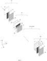
- FIG. 6 shows a detector stack according to a variation of the first embodiment of the present disclosure.
- the detector stack comprises N detectors, or detector units, arranged along the first direction, detectors from U1 to UN.
- N is an integer number equal to, or larger than, three.
- the detectors or detector units of this embodiment may correspond to any of the detectors or detector unit described in the present disclosure.
- the filter stack comprises a first plurality of detectors and a second plurality of detectors, wherein the first plurality and the second plurality are interlaced.
- the first plurality of detectors may include detectors according to FIG. 2A (i.e., with stripes elongated along the third direction).
- the second plurality of detectors may comprise detectors according to FIG. 2B (i.e., with stripes elongated along the second direction).
- the first plurality of detectors and the second plurality of detectors may be interlaced and the respective collection layers 7 may generally be configured to respectively output output signals representing different one-dimensional travel directions of the particles.
- the collection axis of the collection means of the detectors of the first plurality of detectors and the collection axis of the collection means of the detectors of the second plurality of detectors may have at least one different vector components. That is, the collection axis of the collection means 7 of a given detector needs only to have different vector components in the y-z plane with respect to the collection axis of the collection means 7 of the immediate neighboring detectors.
- the detector stack may comprise a number N of detectors.
- Each of the N detectors may be different from the other N-1 detectors of the detectors stack. For instance, each detector may have different collection directions, filtering directions, first tilting angle and/or second tilting angle. Alternatively, each of the N detector may be different from the other N-1 detector in at least one of these properties.
- Each detector of the detector stack comprises photon generation means and collection means.
- the collection means of immediate neighboring detectors in the first direction are configured to respectively output output signals representing different one-dimensional travel directions of the particles.
- Immediate neighboring detectors means that between the two given detectors there are no intervening detectors along the first direction.
- the first direction may be a direction along which the particles are travelling.
- the particle may have, on average, at least a non-zero component of its travel vector along the first direction.
- a plurality of detectors, or detector units are provided.
- the different detectors may be configured to measure particles having different energies. This is possible for instance by configuring the detectors so as to have different absorption properties. This can be achieved by appropriately selecting the number, or physical characteristics, of the absorption layers 2 to 4.
- a first detector U1 may have no absorber layer, whereas a second detector U2 may have one absorber layer 2b.
- a last detector UN may have three absorber layers, 2n to 4n.
- the absorber layers of all the detectors U1 to UN are all configured to absorb a same amount of energy, namely one energy unit. It is also assumed that no other energy loss occurs in the system. In this case, particles impinging on the generation means 5a would have lost no energy due to the interaction with the detector stack. Particles impinging on the generation means 5b would have lost one energy unit due to the crossing of the absorber layer 2b.
- Particles impinging on the generation means 5n of the last detector would have lost four energy units due to the interactions with three absorber layers of the last detector and with the absorber layer of the second detector. Moreover, these particles would have lost additional energy due to the interaction with the absorber layers of the other intervening detectors U3 to UN-1.
- each one of the N detectors is configured to measure respective different energies which can be precisely determined a priory based on the physical properties of the detector stack.
- the number of detectors comprised in the detector stack and the energy each detector of the detector stack is configured to measure can selected based on the expected types of particles making up the impinging particles.
- the detector stack can be built to measure energies close to, at, or substantially at, characteristic features of the particles.
- the number of the detectors in the detector stack and the energy each detector of the detector stack is configured to measure is based on the particles to be measured.
- the types of particles expected is usually a readily know information derivable from the theory describing the physical reaction. Since the output signal (for instance the number of photons) output by each detector of the detector stack is the sum of the signal generated by each particle, information regarding the expected type of particle can be used to deconvolute the output signal and hence determine the actual number of particles per type of particles.
- FIG. 7 shows another variation of the embodiment of the present disclosure.
- FIG. 6 shows that the second detector has one absorber layer and the first detector has no absorber layer the present disclosure is not limited thereto.
- Each detector of the detector stack may have a different number of absorber layers.
- each detector of the detector stack may have a same number of absorber layers.
- FIG. 7 shows a configuration in which each detector of the detector stack has a same number of absorber layers.
- the second embodiment is described with reference to the first embodiment and by placing special emphasis on the differences. For the sake of brevity, the description of similar or corresponding components is not repeated. It will however be readily understood by those skilled in the art that components or elements of the first embodiments may be employed also in connection with the second embodiment, except when explicitly indicated otherwise.
- the generation means 5 may be charged particles generation means 5.
- the generation means may be a metallic plate configured to be charged upon being impinged on by particle.
- the charged particles generation means may be configured to generate electrons (or holes).
- the detector stack may be experimentally calibrated.
- the collection means 7 may be embedded in the generation means 5. That is, the collection means 7 and the generation means may be the same means, i.e., a collection and generation means. For instance, it may be a metallic plate or a layer. The plate may be divided in a plurality of conductive strips. The strips may be both configured to generate electrical charge when impinged on by incident particles and to allow the generated electrical charges to be collected. The conductive stripes may be interlaced with non-conductive stripes to avoid cross talking between neighboring conductive stripes. The collection of the charges may for instance occur at a border of the generation and collection means.
- the collection and generation means may be elongated along the second and the third direction.
- the transport means 8 may be located on a border of the collection and generation means and may be connected to the collection and generation means via collector plates.
- FIG. 8 there is provided a method for detecting energy (spectral distribution) and spatial distribution of particles impinging on the detector stack.
- the method comprises the following steps.
- the particles may comprise (or solely consists of) gamma radiation or generally of ionizing radiation. Therefore, particles may be understood in a broader sense.
- the detector stack may be configured to perform time of flight, TOF, measurements.
- the kinetic energy of a particle also depends on the mass of the particle itself.
- the scintillation materials of all the generation means may be the same material.
- it may be a same organic material.
- it may be a same inorganic material.
Landscapes
- Physics & Mathematics (AREA)
- Health & Medical Sciences (AREA)
- Life Sciences & Earth Sciences (AREA)
- General Physics & Mathematics (AREA)
- High Energy & Nuclear Physics (AREA)
- Molecular Biology (AREA)
- Spectroscopy & Molecular Physics (AREA)
- Measurement Of Radiation (AREA)
Priority Applications (3)
| Application Number | Priority Date | Filing Date | Title |
|---|---|---|---|
| EP23169901.8A EP4455737A1 (de) | 2023-04-25 | 2023-04-25 | Partikeldetektor |
| EP24161461.9A EP4455738A1 (de) | 2023-04-25 | 2024-03-05 | Teilchendetektor |
| US18/637,261 US20240361474A1 (en) | 2023-04-25 | 2024-04-16 | Particle detector |
Applications Claiming Priority (1)
| Application Number | Priority Date | Filing Date | Title |
|---|---|---|---|
| EP23169901.8A EP4455737A1 (de) | 2023-04-25 | 2023-04-25 | Partikeldetektor |
Publications (1)
| Publication Number | Publication Date |
|---|---|
| EP4455737A1 true EP4455737A1 (de) | 2024-10-30 |
Family
ID=86226866
Family Applications (2)
| Application Number | Title | Priority Date | Filing Date |
|---|---|---|---|
| EP23169901.8A Withdrawn EP4455737A1 (de) | 2023-04-25 | 2023-04-25 | Partikeldetektor |
| EP24161461.9A Pending EP4455738A1 (de) | 2023-04-25 | 2024-03-05 | Teilchendetektor |
Family Applications After (1)
| Application Number | Title | Priority Date | Filing Date |
|---|---|---|---|
| EP24161461.9A Pending EP4455738A1 (de) | 2023-04-25 | 2024-03-05 | Teilchendetektor |
Country Status (2)
| Country | Link |
|---|---|
| US (1) | US20240361474A1 (de) |
| EP (2) | EP4455737A1 (de) |
Cited By (1)
| Publication number | Priority date | Publication date | Assignee | Title |
|---|---|---|---|---|
| JP2024510556A (ja) * | 2021-03-03 | 2024-03-08 | シメトリカ リミテッド | 線量計装置および方法 |
Citations (2)
| Publication number | Priority date | Publication date | Assignee | Title |
|---|---|---|---|---|
| WO2015189601A1 (en) * | 2014-06-09 | 2015-12-17 | University Of Lincoln | Assembly, apparatus, system and method |
| WO2022185032A1 (en) * | 2021-03-03 | 2022-09-09 | Symetrica Limited | Dosimeter apparatus and methods |
Family Cites Families (30)
| Publication number | Priority date | Publication date | Assignee | Title |
|---|---|---|---|---|
| US4749863A (en) * | 1984-12-04 | 1988-06-07 | Computer Technology And Imaging, Inc. | Two-dimensional photon counting position encoder system and process |
| US4845731A (en) * | 1985-06-05 | 1989-07-04 | Picker International | Radiation data acquistion |
| US5171998A (en) * | 1990-06-14 | 1992-12-15 | Engdahl John C | Gamma ray imaging detector |
| US20050017185A1 (en) * | 2003-07-01 | 2005-01-27 | King Douglas Beverley Stevenson | Radiation detector |
| JP2007526475A (ja) * | 2004-03-05 | 2007-09-13 | コーニンクレッカ フィリップス エレクトロニクス エヌ ヴィ | 可変反射体を有するx線検出器用シンチレータ |
| US7515689B2 (en) * | 2005-01-27 | 2009-04-07 | Hitachi Medical Corporation | X-ray measuring instrument |
| EP1847855A1 (de) * | 2006-04-18 | 2007-10-24 | ETH Zürich | Verfahren zur Überwachung eines unbekannten Behälters oder des Inhalts in einem Volumen, Überwachungssystem zur Anwendung mit diesem Verfahren und Strahlungsdetektor für ein derartiges Überwachungssystem |
| GB0709381D0 (en) * | 2007-05-15 | 2007-06-27 | Petrra Ltd | Radiation detector |
| JP5701743B2 (ja) * | 2008-03-19 | 2015-04-15 | コーニンクレッカ フィリップス エヌ ヴェ | 放射線検出器、画像システム、光子を検出するための方法及びその方法を実行するコンピュータプログラム |
| EP2366172B1 (de) * | 2008-11-26 | 2013-04-10 | Analogic Corporation | Verfahren und vorrichtung zur continuous-wave-tomosynthese unter verwendung von photonenzählung |
| JP5213923B2 (ja) * | 2010-01-29 | 2013-06-19 | キヤノン株式会社 | X線撮像装置およびx線撮像方法 |
| NO333637B1 (no) * | 2010-03-25 | 2013-07-29 | Visuray Technology Ltd | Apparat for registrering av fotoner og ioniserende partikler med samtidig retningsbestemmelse av et utgangspunkt i en fluidfylt ledning for hvert foton eller ioniserende partikkel |
| WO2012080927A2 (en) * | 2010-12-13 | 2012-06-21 | Koninklijke Philips Electronics N.V. | Radiation detector with photodetectors |
| CA2874397C (en) * | 2011-05-24 | 2019-09-24 | Universite Laval | Methods and apparatus for optically encoded position multiple-point scintillation detector using a single collecting light guide |
| US20130009066A1 (en) * | 2011-07-06 | 2013-01-10 | Siemens Aktiengesellschaft | Block Detector With Variable Microcell Size For Optimal Light Collection |
| US9029800B2 (en) * | 2011-08-09 | 2015-05-12 | Palo Alto Research Center Incorporated | Compact analyzer with spatial modulation and multiple intensity modulated excitation sources |
| GB2494123A (en) * | 2011-08-30 | 2013-03-06 | Ucl Business Plc | Radiation Detector |
| FR3003652A1 (fr) * | 2013-03-25 | 2014-09-26 | Commissariat Energie Atomique | Detecteur de traces de particules ionisantes |
| US8921796B1 (en) * | 2013-08-27 | 2014-12-30 | Siemens Medical Solutions Usa, Inc. | Multiple discriminator PET with pileup event detection |
| US20150078513A1 (en) * | 2013-09-13 | 2015-03-19 | Seung H. Baek | Dental x-ray imaging system having higher spatial resolution |
| EP2871496B1 (de) * | 2013-11-12 | 2020-01-01 | Samsung Electronics Co., Ltd | Strahlungsdetektor und Computertomografievorrichtung damit |
| EP3082608B1 (de) * | 2013-12-18 | 2018-11-21 | Koninklijke Philips N.V. | Bildgebungssystem mit photonenzählungsdetektor |
| EP2919037A1 (de) * | 2014-03-13 | 2015-09-16 | Université de Technologie de Troyes | Optimierungsverfahren der Sammlung von Photonen in Szintillationskristallen, entsprechender Kristall und entsprechende Anwendungen |
| JP2016061655A (ja) * | 2014-09-17 | 2016-04-25 | 株式会社東芝 | シンチレータ、放射線検出装置および放射線検査装置 |
| KR101664137B1 (ko) * | 2014-12-30 | 2016-10-10 | 삼성전자주식회사 | 검출기 어셈블리, 이를 포함하는 컴퓨터 단층 촬영 장치 및 그 제어방법 |
| US10663608B2 (en) * | 2015-09-21 | 2020-05-26 | Shanghai United Imaging Healthcare Co., Ltd. | System and method for calibrating a PET scanner |
| US11076821B2 (en) * | 2015-11-25 | 2021-08-03 | The Regents Of The University Of California | 3D-beam modulation filter for equalizing dose and image quality in breast CT |
| CN105433973B (zh) * | 2015-12-30 | 2018-09-18 | 沈阳东软医疗系统有限公司 | Ct扫描设备、ct系统和控制过滤器组件的方法及装置 |
| CN106226339A (zh) * | 2016-09-20 | 2016-12-14 | 清华大学 | 中子产生设备,中子成像设备以及成像方法 |
| US12130393B2 (en) * | 2022-09-30 | 2024-10-29 | United States Of America As Represented By The Secretary Of The Navy | Layered scintillating neutron detector |
-
2023
- 2023-04-25 EP EP23169901.8A patent/EP4455737A1/de not_active Withdrawn
-
2024
- 2024-03-05 EP EP24161461.9A patent/EP4455738A1/de active Pending
- 2024-04-16 US US18/637,261 patent/US20240361474A1/en active Pending
Patent Citations (2)
| Publication number | Priority date | Publication date | Assignee | Title |
|---|---|---|---|---|
| WO2015189601A1 (en) * | 2014-06-09 | 2015-12-17 | University Of Lincoln | Assembly, apparatus, system and method |
| WO2022185032A1 (en) * | 2021-03-03 | 2022-09-09 | Symetrica Limited | Dosimeter apparatus and methods |
Non-Patent Citations (1)
| Title |
|---|
| HUAULT ET AL.: "A 2D scintillator-based proton detector for high repetition rate experiments", BEAM LINE AND INSTRUMENTATION: FOURTH WORKSHOP, MONDAY - TUESDAY 11, 12 May 2020 (2020-05-12) |
Cited By (1)
| Publication number | Priority date | Publication date | Assignee | Title |
|---|---|---|---|---|
| JP2024510556A (ja) * | 2021-03-03 | 2024-03-08 | シメトリカ リミテッド | 線量計装置および方法 |
Also Published As
| Publication number | Publication date |
|---|---|
| US20240361474A1 (en) | 2024-10-31 |
| EP4455738A1 (de) | 2024-10-30 |
Similar Documents
| Publication | Publication Date | Title |
|---|---|---|
| Adamczyk et al. | The BRAHMS experiment at RHIC | |
| EP1984753B1 (de) | VERFAHREN UND VORRICHTUNG ZUR BESTIMMUNG der Strahlendosis | |
| US9488602B2 (en) | Radioactive substance detection device, radiation source location visibility system, and radioactive substance detection method | |
| KR20190058193A (ko) | 뮤온 검출기 및 이를 포함하는 뮤온 검출시스템 | |
| EP4455738A1 (de) | Teilchendetektor | |
| Kellie et al. | A tagged photon spectrometer for use with the Mainz 180 MeV microtron | |
| Minami et al. | 2-mm-thick large-area CdTe double-sided strip detectors for high-resolution spectroscopic imaging of X-ray and gamma-ray with depth-of-interaction sensing | |
| Kurz et al. | Two-dimensional neutron detector based on a position-sensitive photomultiplier | |
| CN112285757A (zh) | 辐射监测装置与方法 | |
| Mazzitelli et al. | A high resolution tpc based on gem optical readout | |
| Novotny et al. | A plastic-BaF/sub 2/phoswich telescope for charged/neutral particle and photon detection | |
| Hailey et al. | An inexpensive, hard x-ray imaging spectrometer for use in x-ray astronomy and atomic physics | |
| Woolf et al. | An active interrogation detection system (ACTINIDES) based on a dual fast neutron/gamma-ray coded aperture imager | |
| Matteson et al. | Charge collection studies of a high resolution CZT-based detector for PET | |
| Perdikakis et al. | LENDA: A Low Energy Neutron Detector Array for Studies of $(p, n) $ Reactions With Radioactive Beams | |
| Antochi et al. | A GEM-based optically readout time projection chamber for charged particle tracking | |
| Freeman et al. | New focal plane detector system for the rochester recoil mass spectrometer | |
| Beattie | Measurement of the Beam Asymmetry for the ETA and ETA Prime Mesons with the GlueX Experiment | |
| da Silva et al. | Cadmium (Zinc) telluride 2D/3D spectrometers for scattering polarimetry | |
| Huck | Investigations of muon detection with the CALICE Analog Hadron Calorimeter | |
| Doria et al. | Shedding light on X17 | |
| Wolfs et al. | Segmented focal plane detector for light and heavy ions | |
| Li et al. | The study of a new longitudinal segmented shashlik electromagnetic calorimeter | |
| Teilab | The production of eta and omega mesons in 3.5 GeV p+ p interaction in HADES | |
| Akhdar | Development of a high resolution 3D gamma camera |
Legal Events
| Date | Code | Title | Description |
|---|---|---|---|
| PUAI | Public reference made under article 153(3) epc to a published international application that has entered the european phase |
Free format text: ORIGINAL CODE: 0009012 |
|
| STAA | Information on the status of an ep patent application or granted ep patent |
Free format text: STATUS: THE APPLICATION HAS BEEN PUBLISHED |
|
| AK | Designated contracting states |
Kind code of ref document: A1 Designated state(s): AL AT BE BG CH CY CZ DE DK EE ES FI FR GB GR HR HU IE IS IT LI LT LU LV MC ME MK MT NL NO PL PT RO RS SE SI SK SM TR |
|
| STAA | Information on the status of an ep patent application or granted ep patent |
Free format text: STATUS: THE APPLICATION IS DEEMED TO BE WITHDRAWN |
|
| 18D | Application deemed to be withdrawn |
Effective date: 20250501 |