EP4455694A1 - Noise inflow analysis apparatus and method - Google Patents
Noise inflow analysis apparatus and method Download PDFInfo
- Publication number
- EP4455694A1 EP4455694A1 EP23204484.2A EP23204484A EP4455694A1 EP 4455694 A1 EP4455694 A1 EP 4455694A1 EP 23204484 A EP23204484 A EP 23204484A EP 4455694 A1 EP4455694 A1 EP 4455694A1
- Authority
- EP
- European Patent Office
- Prior art keywords
- electromagnetic wave
- noise
- intensity
- monitoring data
- electromagnetic
- Prior art date
- Legal status (The legal status is an assumption and is not a legal conclusion. Google has not performed a legal analysis and makes no representation as to the accuracy of the status listed.)
- Pending
Links
Images




Classifications
-
- G—PHYSICS
- G01—MEASURING; TESTING
- G01R—MEASURING ELECTRIC VARIABLES; MEASURING MAGNETIC VARIABLES
- G01R31/00—Arrangements for testing electric properties; Arrangements for locating electric faults; Arrangements for electrical testing characterised by what is being tested not provided for elsewhere
- G01R31/36—Arrangements for testing, measuring or monitoring the electrical condition of accumulators or electric batteries, e.g. capacity or state of charge [SoC]
- G01R31/3644—Constructional arrangements
- G01R31/3648—Constructional arrangements comprising digital calculation means, e.g. for performing an algorithm
-
- G—PHYSICS
- G01—MEASURING; TESTING
- G01R—MEASURING ELECTRIC VARIABLES; MEASURING MAGNETIC VARIABLES
- G01R29/00—Arrangements for measuring or indicating electric quantities not covered by groups G01R19/00 - G01R27/00
- G01R29/08—Measuring electromagnetic field characteristics
- G01R29/0807—Measuring electromagnetic field characteristics characterised by the application
- G01R29/0814—Field measurements related to measuring influence on or from apparatus, components or humans, e.g. in ESD, EMI, EMC, EMP testing, measuring radiation leakage; detecting presence of micro- or radiowave emitters; dosimetry; testing shielding; measurements related to lightning
-
- B—PERFORMING OPERATIONS; TRANSPORTING
- B60—VEHICLES IN GENERAL
- B60L—PROPULSION OF ELECTRICALLY-PROPELLED VEHICLES; SUPPLYING ELECTRIC POWER FOR AUXILIARY EQUIPMENT OF ELECTRICALLY-PROPELLED VEHICLES; ELECTRODYNAMIC BRAKE SYSTEMS FOR VEHICLES IN GENERAL; MAGNETIC SUSPENSION OR LEVITATION FOR VEHICLES; MONITORING OPERATING VARIABLES OF ELECTRICALLY-PROPELLED VEHICLES; ELECTRIC SAFETY DEVICES FOR ELECTRICALLY-PROPELLED VEHICLES
- B60L58/00—Methods or circuit arrangements for monitoring or controlling batteries or fuel cells, specially adapted for electric vehicles
- B60L58/10—Methods or circuit arrangements for monitoring or controlling batteries or fuel cells, specially adapted for electric vehicles for monitoring or controlling batteries
- B60L58/16—Methods or circuit arrangements for monitoring or controlling batteries or fuel cells, specially adapted for electric vehicles for monitoring or controlling batteries responding to battery ageing, e.g. to the number of charging cycles or the state of health [SoH]
-
- G—PHYSICS
- G01—MEASURING; TESTING
- G01R—MEASURING ELECTRIC VARIABLES; MEASURING MAGNETIC VARIABLES
- G01R23/00—Arrangements for measuring frequencies; Arrangements for analysing frequency spectra
- G01R23/16—Spectrum analysis; Fourier analysis
- G01R23/20—Measurement of non-linear distortion
-
- G—PHYSICS
- G01—MEASURING; TESTING
- G01R—MEASURING ELECTRIC VARIABLES; MEASURING MAGNETIC VARIABLES
- G01R29/00—Arrangements for measuring or indicating electric quantities not covered by groups G01R19/00 - G01R27/00
- G01R29/08—Measuring electromagnetic field characteristics
- G01R29/0864—Measuring electromagnetic field characteristics characterised by constructional or functional features
- G01R29/0878—Sensors; antennas; probes; detectors
-
- G—PHYSICS
- G01—MEASURING; TESTING
- G01R—MEASURING ELECTRIC VARIABLES; MEASURING MAGNETIC VARIABLES
- G01R29/00—Arrangements for measuring or indicating electric quantities not covered by groups G01R19/00 - G01R27/00
- G01R29/08—Measuring electromagnetic field characteristics
- G01R29/0864—Measuring electromagnetic field characteristics characterised by constructional or functional features
- G01R29/0892—Details related to signal analysis or treatment; presenting results, e.g. displays; measuring specific signal features other than field strength, e.g. polarisation, field modes, phase, envelope, maximum value
-
- G—PHYSICS
- G01—MEASURING; TESTING
- G01R—MEASURING ELECTRIC VARIABLES; MEASURING MAGNETIC VARIABLES
- G01R31/00—Arrangements for testing electric properties; Arrangements for locating electric faults; Arrangements for electrical testing characterised by what is being tested not provided for elsewhere
- G01R31/36—Arrangements for testing, measuring or monitoring the electrical condition of accumulators or electric batteries, e.g. capacity or state of charge [SoC]
- G01R31/3644—Constructional arrangements
- G01R31/3646—Constructional arrangements for indicating electrical conditions or variables, e.g. visual or audible indicators
-
- G—PHYSICS
- G01—MEASURING; TESTING
- G01R—MEASURING ELECTRIC VARIABLES; MEASURING MAGNETIC VARIABLES
- G01R31/00—Arrangements for testing electric properties; Arrangements for locating electric faults; Arrangements for electrical testing characterised by what is being tested not provided for elsewhere
- G01R31/36—Arrangements for testing, measuring or monitoring the electrical condition of accumulators or electric batteries, e.g. capacity or state of charge [SoC]
- G01R31/367—Software therefor, e.g. for battery testing using modelling or look-up tables
-
- G—PHYSICS
- G01—MEASURING; TESTING
- G01R—MEASURING ELECTRIC VARIABLES; MEASURING MAGNETIC VARIABLES
- G01R31/00—Arrangements for testing electric properties; Arrangements for locating electric faults; Arrangements for electrical testing characterised by what is being tested not provided for elsewhere
- G01R31/36—Arrangements for testing, measuring or monitoring the electrical condition of accumulators or electric batteries, e.g. capacity or state of charge [SoC]
- G01R31/392—Determining battery ageing or deterioration, e.g. state of health
-
- G—PHYSICS
- G01—MEASURING; TESTING
- G01R—MEASURING ELECTRIC VARIABLES; MEASURING MAGNETIC VARIABLES
- G01R33/00—Arrangements or instruments for measuring magnetic variables
- G01R33/02—Measuring direction or magnitude of magnetic fields or magnetic flux
-
- G—PHYSICS
- G01—MEASURING; TESTING
- G01R—MEASURING ELECTRIC VARIABLES; MEASURING MAGNETIC VARIABLES
- G01R33/00—Arrangements or instruments for measuring magnetic variables
- G01R33/12—Measuring magnetic properties of articles or specimens of solids or fluids
- G01R33/16—Measuring susceptibility
-
- Y—GENERAL TAGGING OF NEW TECHNOLOGICAL DEVELOPMENTS; GENERAL TAGGING OF CROSS-SECTIONAL TECHNOLOGIES SPANNING OVER SEVERAL SECTIONS OF THE IPC; TECHNICAL SUBJECTS COVERED BY FORMER USPC CROSS-REFERENCE ART COLLECTIONS [XRACs] AND DIGESTS
- Y02—TECHNOLOGIES OR APPLICATIONS FOR MITIGATION OR ADAPTATION AGAINST CLIMATE CHANGE
- Y02E—REDUCTION OF GREENHOUSE GAS [GHG] EMISSIONS, RELATED TO ENERGY GENERATION, TRANSMISSION OR DISTRIBUTION
- Y02E60/00—Enabling technologies; Technologies with a potential or indirect contribution to GHG emissions mitigation
- Y02E60/10—Energy storage using batteries
Definitions
- the present disclosure relates to an electromagnetic penetration analysis apparatus and method.
- the electromagnetic susceptibility (EMS) test is an immunity test that the normal operation of the device may not be affected by all electromagnetic waves existing in the surroundings.
- the EMS test may be measured by supplying electromagnetic noise to the device.
- the EMS test for the battery management device determines whether the device operates normally based on the functional state variables of the battery management device, the degree of influence of the electromagnetic wave noise applied to the battery management device to the functional blocks of the battery management device is not considered. Therefore, there is a limit to the preliminary risk derivation of the battery management device and precautions in design stage, for the EMS test until the actual test is performed.
- At least one embodiment of the embodiments is to provide a noise penetration analysis device and method capable of quantifying the degree of influence of electromagnetic wave noise applied for an EMS test on functional blocks of a battery management device.
- an electromagnetic noise penetration analysis apparatus for analyzing electromagnetic wave noise penetrating a battery management device that manages at least one battery module and comprises a plurality of functional blocks.
- the electromagnetic noise penetration analysis apparatus includes: at least one near-field measurement probe configured to measure intensity of the magnetic field while electromagnetic noise of a frequency applied when the first monitoring data operating abnormally is obtained through the electromagnetic wave immunity test among the plurality of functional blocks is applied; and an analyzer configured to quantify intensity of electromagnetic wave noise received by the at least one functional block based on the intensity of the magnetic field.
- the electromagnetic noise penetration analysis apparatus may further include a receiver configured to obtain frequency information of electromagnetic noise applied when the first monitoring data is obtained in the electromagnetic wave immunity test and the first monitoring data.
- the at least one near-field measurement probe may be configured to respond to the frequency applied when the first monitoring data is obtained.
- the at least one near-field measurement probe may be configured to disposed at a position of at least one functional block associated with the first monitoring data among the plurality of functional blocks.
- the position of the at least one function block may include a position on a path connected to the at least one function block.
- a method for analyzing electromagnetic wave noise penetrating a device under test for testing electromagnetic wave immunity includes: obtaining first data that operate abnormally through an electromagnetic wave immunity test and frequency information of an electromagnetic wave noise applied to the device under test; measuring intensity of the magnetic field through at least one near-field measurement probe disposed at a position of at least one functional block associated with the first monitoring data among a plurality of functional blocks comprised in the device under test while the electromagnetic wave noise is applied; and quantifying intensity of electromagnetic wave noise received by the at least one functional block based on the intensity of the magnetic field.
- the at least one near-field measurement probe may be configured to respond a frequency applied when the first monitoring data is obtained.
- the position of the at least one function block may include a position on a path connected to the at least one function block.
- the device under test may be a battery management device that manages at least one battery module.
- the method may further include determining at least one defect generation mechanism based on the quantified intensity of electromagnetic wave noise received by the at least one functional block.
- the method may further include establishing at least one countermeasure for the defect generation mechanism.
- first, second, etc. may be used to describe various elements, but the elements are not limited by the terms. The above terms are used only for the purpose of distinguishing one element from another element. For example, without departing from the scope of the present disclosure, a first element may be referred to as a second element, and similarly, a second element may be referred to as a first element.
- a component when referred to be "connected” with another component, it includes not only the case where two components are “directly connected” but also the case where two components are “indirectly or non-contactedly connected” with another component interposed therebetween, or the case where two components are “electrically connected.”
- an element when referred to as “directly connected” to another element, it should be understood that no other element exists in the middle.
- FIG. 1 is a diagram schematically illustrating a battery pack according to an embodiment.
- the battery pack 10 may be mounted in various power devices that use electrical energy stored in the battery pack 10, such as an electric vehicle.
- the battery pack 10 may include a plurality of battery modules 20a, 20b, and 20c connected in series with each other and the battery management device 30.
- the plurality of battery modules 20a, 20b, and 20c connected in series with each other may be connected to an external charging device or load through system terminals T+ and T-, and may be charged by the charging device or discharged by the load.
- the battery module 20a may include a plurality of battery cells 22a electrically connected to each other in series and/or parallel.
- the battery module 20b may include a plurality of battery cells 22b electrically connected to each other in series and/or parallel.
- the battery module 20c may include a plurality of battery cells 22c electrically connected to each other in series and/or parallel.
- the battery management device 30 may manage the battery modules 20a, 20b, and 20c by monitoring the voltages, currents, and temperatures of the battery modules 20a, 20b, and 20c.
- the battery management device 30 may include a plurality of slave battery management systems (BMS) 100a, 100b, and 100c and a master BMS 200.
- BMS slave battery management systems
- FIG. 1 it will be described that the battery pack 10 includes three battery modules 20a, 20b and 20c, and the wireless battery management device 30 includes three slave BMS 100a, 100b, and 100c.
- the plurality of slave BMSs 100a, 100b, and 100c may be installed to correspond to the plurality of battery modules 20a, 20b, and 20c included in the battery pack 10 on a one-to-one basis.
- Each of the plurality of slave BMSs 100a, 100b, and 100c may be electrically connected to any one battery module 20a, 20b, and 20c in which it is installed among the plurality of battery modules 20a, 20b, and 20c.
- the slave BMS 100a may be electrically connected to the battery module 20a
- the slave BMS 100b may be electrically connected to the battery module 20b
- the slave BMS 100c may be electrically connected to the battery module 20c.
- Each of the plurality of slave BMSs 100a, 100b, and 100c may be electrically connected to at least one temperature sensor 32a, 32b, and 32c.
- the at least one temperature sensor 32a, 32b, and 32c may measure the temperature of the corresponding battery module 20a, 20b, and 20c, respectively.
- Each of the plurality of slave BMSs 100a, 100b, and 100c may measure information of the corresponding battery modules 20a, 20b, and 20c and transmit the measured information to the master BMS 200.
- the information of the battery modules 20a, 20b, and 20c may include, for example, the currents and voltages of the battery modules 20a, 20b, and 20c, the voltages and temperatures of the battery cells 22a, 22b, and 22c, and the ambient temperature.
- the master BMS 200 may periodically obtain information about the battery modules 20a, 20b, and 20c measured by the plurality of slave BMSs 100a, 100b, and 100c.
- the master BMS 200 may perform control functions such as state of charge (SOC), power control, cell balancing control, failure diagnosis control, cooling control, and thermal runaway detection control based on the information of the battery modules 20a, 20b, and 20c obtained from the plurality of slave BMSs 100a, 100b, and 100c.
- the master BMS 200 may control a relay for supplying and disconnecting the power of the battery modules 20a, 20b, and 20c to and from the load based on the information of the battery modules 20a, 20b, and 20c.
- the master BMS 200 may be connected to a plurality of slave BMSs 100a, 100b, and 100c through wired communication lines.
- the master BMS 200 may be connected to a plurality of slave BMSs 100a, 100b, and 100c using a wireless network as a connection method.
- FIG. 2 is a diagram illustrating an example of a slave BMS shown in FIG. 1 .
- the slave BMS 100a may include an analog front end (AFE) integrated circuit (IC) 110, a micro control unit (MCU) 120, a communicator 130, and a memory 140.
- AFE analog front end
- MCU micro control unit
- the AFE IC 110 may be electrically connected to at least one temperature sensor 32a.
- the AFE IC 110 may be electrically connected to both ends of the battery module 20a.
- the AFE IC 110 may be electrically connected to both ends of each battery cell 22a constituting the battery module 20a.
- the AFE IC 110 may measure monitoring data such as voltages, currents, temperatures, remaining power amount, lifespan, and state of charge of the battery module 20a including at least one battery cell 22a.
- the master BMS 200 may measure the charging current and discharging current of the battery module 20a.
- the MCU 120 performs various control functions (e.g., charging, discharge, balancing) for adjusting the state of the battery module 20a electrically connected thereto, based on the monitoring data of the battery module 20a measured by the AFE IC 110.
- each control function is directly performed by each slave BMS 100a, 100b, and 100c based on the state of the battery module 20a, 20b, and 20c or may be performed according to a command from the master BMS 200.
- the communicator 130 may communicate with the master BMS 200.
- the communicator 130 may transmit monitoring data of the battery module 20a measured by the AFE IC 110 to the master BMS 200.
- the memory 140 may store monitoring data of the battery module 20a measured by the AFE IC 110.
- FIG. 3 is a diagram illustrating an example of a master BMS shown in FIG. 1 .
- the master BMS 200 may include a power supply part 210, a power distribution part 220, a digital input part 230, an analog input part 240, a digital output part 250, a communicator 260, and an MCU 270.
- the power supply part 210 may protect functional blocks of the master BMS 200 from overcurrent or noise coming through a power supply connected to drive the master BMS 200.
- the power distribution part 220 may convert power connected to drive the master BMS 200 according to input power specifications of a load connected to the master BMS 200 and supply the converted power to a corresponding load.
- the power distribution part 220 may distribute and supply power to loads such as, for example, a contactor, a battery disconnecting unit (BDU), a sensor, and a heater.
- loads such as, for example, a contactor, a battery disconnecting unit (BDU), a sensor, and a heater.
- the digital input part 230 may receive various digital signals and transmit the received digital signals to the MCU 270.
- the digital signal includes, for example, an ignition signal Ignition for switching the battery management device 30 from a sleep mode to an active mode as an ignition device is turned on if the vehicle is started, and a collision detection signal Crash of the vehicle, a pump diagnosis signal Pump Diagnosis received from the oil pump controller, and a signal Contactor In confirming that the contactor is operating normally.
- the analog input part 240 may receive information sensed from various sensors inside the battery pack 10 and transmit the sensed information to the MCU 270.
- Various sensors inside the battery pack 10 may include, for example, a temperature sensor for measuring the temperature of the battery pack 10 or a current sensor for sensing the amount of current supplied from the battery pack 10 to a load.
- the digital output part 250 may output a switch control signal transmitted from the MCU 270 to a switch such as a relay or a contactor, and may output a pump control signal to a pump.
- the communicator 260 may perform communication with an external controller of the battery pack 10, slave BMSs 100a, 100b, and 100c, and a BDU.
- the external controller of the battery pack 10 may include, for example, a vehicle controller such as an electronic control unit (ECU).
- the communicator 260 may perform CAN communication with an external controller or BDU of the battery pack 10. Also, the communicator 260 may support Local Interconnect Network (LIN) communication.
- LIN Local Interconnect Network
- the MCU 270 may manage the status of the slave BMSs 100a, 100b, and 100c, and may perform control functions such as SOC, power limitation, cell balancing, fault diagnosis, cooling control, etc. based on the monitoring data received from the slave BMSs 100a, 100b, and 100c, and control a switch such as a relay or contactor.
- the MCU 270 may perform a fault diagnosis function of the battery pack 10 based on monitoring data received from the slave BMSs 100a, 100b, and 100c and monitoring data sensed by various sensors.
- the MCU 270 may detect various failures such as overvoltage, undervoltage, battery cell failure, current sensor failure, temperature sensor failure, disconnection/short circuit, cooling fan failure, communication failure, and relay fusion.
- the MCU 270 may output switch control signals to switches such as a relay or contactor to supply or cut off the power of the battery pack 10 to a load, and output a control pump control signal for adjusting the speed of the pump to match the proper temperature of the battery cells.
- the MCU 270 may diagnose each digital signal according to predetermined algorithms using various digital signals input through the digital input part 230, and cut off the power of the battery pack 10 based on the diagnosis result or transmit a warning signal for an abnormal situation to the vehicle.
- the MCU 270 may detect connection state of the high-voltage components of the battery pack 10 through a high voltage interlock loop (HVIL), and may cut off power supply of the battery pack 10 based on the connection state of the high-voltage components of the battery pack 10.
- HVIL high voltage interlock loop
- the master BMS 200 may further include, for example, a function block corresponding to a real time clock (RTC) or a watchdog 290 in addition to the aforementioned power supply 210, power distribution part 220, digital input part 230, analog input part 240, digital output part 250, communicator 260, and MCU 270.
- RTC real time clock
- the RTC 280 is a kind of clock that operates within the master BMS 200 and may record the time when an event that meets a predetermined condition of a non-active state or a function to be monitored occurs.
- the watchdog 290 may perform a function of safely opening a switch such as a relay or contactor if a failure occurs in the MCU 270.
- the functional blocks of the master BMS 200 shown in FIG. 3 are just one example, and various other functional blocks may be included.
- FIG. 4 is a diagram showing an electromagnetic wave immunity test apparatus according to an embodiment.
- the electromagnetic wave immunity test apparatus 400 is a device that generates electromagnetic wave noise and radiates it to the battery management device 30 of the battery pack 10 for the electromagnetic wave immunity test.
- the electromagnetic wave immunity test apparatus 400 may include a signal generator 410, an antenna 420, and a controller 430.
- the signal generator 410 may generate electromagnetic wave noise for the immunity test according to the control of the controller 430.
- the electromagnetic wave noise of 100 kHz to 6 GHz can be mainly used for the electromagnetic wave immunity test of automobiles.
- the signal generator 410 may generate electromagnetic wave noise of the entire frequency band while changing the frequency according to the control of the controller 430 so as to test electromagnetic wave immunity across the entire frequency band.
- the antenna 420 may radiate electromagnetic wave noise generated under the control of the controller 430.
- the electromagnetic wave noise may be indirectly applied to the battery management device 30 through the antenna 420, or may be directly applied to a harness connected to a communicator through which the battery management device 30 communicates with the controller of the vehicle. Furthermore, the electromagnetic wave noise may be directly applied to a harness connected to other devices of the vehicle using the high voltage output from the battery module or the low voltage supplied from the battery management device 30.
- the controller 430 may control the signal generator 410 and the antenna 420.
- the controller 430 may control the signal generator 410 and the antenna 420 to test electromagnetic wave immunity over the entire frequency band.
- the signal generator 410 may generate electromagnetic wave noise of a first frequency under the control of the controller 430, and the antenna 420 may radiate electromagnetic wave noise of the first frequency for a set time under the control of the controller 430.
- the signal generator 410 may generate electromagnetic wave noise of a second frequency by changing the frequency under the control of the controller 430, and the antenna 420 may radiate electromagnetic wave noise of the second frequency for a set time under the control of the controller 430.
- the controller 430 may control the signal generator 410 and the antenna 420 to test electromagnetic wave immunity over the entire frequency band.
- the diagnosis apparatus 300 may be connected to the battery pack 10 from which electromagnetic noise is radiated, for example, the battery management device 30 of the battery pack 10.
- the battery management device 30 may collect information observed by the battery management device 30, that is, monitoring data, and transmit the collected monitoring data to the diagnosis apparatus 300.
- the diagnosis apparatus 300 may diagnose electromagnetic wave immunity of the battery management device 30, based on radiation time of the electromagnetic wave noise from the electromagnetic wave immunity test apparatus 400, electromagnetic wave noise frequency, and the monitoring data collected by the battery management device 30 in response to radiation of electromagnetic noise.
- the diagnosis apparatus 300 may output an electromagnetic wave immunity diagnosis result of the battery management device 30.
- the electromagnetic wave immunity diagnosis result may include a monitoring variable (data) abnormally operating in the process of applying the electromagnetic wave noise and a frequency range of the electromagnetic wave noise applied at this time.
- Monitoring variable (data) operating abnormally are variables used to monitor the state of a monitored device whose received values are outside a normal range for the monitored device and provide an indication that the device is operating abnormally.
- a monitoring variable (data) operating abnormally may also be referred to as abnormal monitoring data, data that indicate abnormal operation of the device or a monitored variable which indicates abnormal operation of a tested device.
- the diagnosis apparatus 300 may receive whether or not there is an abnormality from the battery management device 30 of the battery pack 10, and a warning signal if an abnormality occurs, or may perform some diagnosis operations.
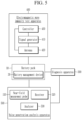
- FIG. 5 is a diagram illustrating a noise penetration analysis apparatus according to an embodiment.
- the noise penetration analysis apparatus 500 may include at least one near-field measurement probe 510, a receiver 520, and an analyzer 530.
- the receiver 520 may receive information including a monitoring variable operating abnormally in the process of applying the electromagnetic wave noise and a corresponding frequency range.
- the receiver 520 may receive information including the monitoring variable operating abnormally and corresponding frequency range from the diagnosis apparatus 300 or from a user. In other words, the receiver receives monitoring variable data which indicate that the device under electromagnetic immunity test is operating abnormally.
- the receiver 520 may transmit the received information to the analyzer 530.
- the receiver 520 may receive the intensity of the magnetic field measured by the at least one near-field measurement probe 510, and may receive the intensity of the magnetic field measured by the at least one near-field measurement probe 510 by the analyzer 530.
- the user may dispose at least one near-field measurement probe 510 based on information about a monitoring variable operating abnormally in the process of applying electromagnetic wave noise and a corresponding frequency range.
- the at least one near-field measurement probe 510 may be configured or configurable to respond sensitively to a frequency range of electromagnetic wave noise in which an abnormally operating monitoring variable is observed.
- the at least one near-field measurement probe 510 may be disposed at a position on a functional block and/or path associated with a monitoring variable that operates abnormally in the battery management device 30.
- the at least one near-field measurement probe 510 may measure the intensity of the magnetic field [A/m] at the location where it is disposed and transmit the measured intensity of the magnetic field to the receiver 520.
- the analyzer 530 may quantify the intensity of electromagnetic wave noise in a functional block and/or path affected by electromagnetic wave noise based on the intensity of the magnetic field [A/m] measured through the near-field measurement probe 510.
- Electromagnetic waves may exist in the form of an electric field, a magnetic field, and an electromagnetic field, and may appear individually or in an overlapping form. Accordingly, the analyzer 530 may approximately quantify the intensity of electromagnetic wave noise based on the intensity of the magnetic field [A/m].
- FIG. 6 is a flowchart illustrating a noise penetration analysis method according to an embodiment
- FIG. 7 is a view showing an example of arrangement positions of the near-field measurement probes shown in FIG. 5 .
- the noise penetration analysis apparatus 500 may receive monitoring variables of the battery management device 30 that is operating abnormally in the electromagnetic wave immunity test and frequency information of corresponding electromagnetic wave noise (S610).
- At least one near-field measurement probe 510 configured or configurable to sensitively respond to a frequency range of electromagnetic wave noise in which an abnormally operating monitoring variable is observed may be disposed on a functional block and/or path associated with the abnormally operating monitoring variable.
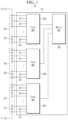
- the battery management device 30 may include many discrete and/or monolithic electrical device components and/or component modules known to those of ordinary skill in the art collectively and/or individually as "electrical components.” These electrical components are internal to the DUT, such as internal to battery management device 30 as depicted by Fig. 7 . Electrical components may be grouped or act individually to perform functions as represented, for example, by a function block A, a function block B, and a function block C. Function block A, function block B, and function block C may be part of the components of the slave BMSs 100a, 100b, and 100c and the master BMS 200 described based on FIGS. 2 and 3 .
- At least one near-field measuring probe 510 may be positioned near or adjacent the identified susceptible electrical component or near or on any path connected to that component.
- the electromagnetic wave immunity test apparatus 400 may radiate electromagnetic wave noise at a frequency at which an abnormally operating monitoring variable is observed to the battery management device 30.
- the noise penetration analysis apparatus 500 may measure intensity of the magnetic field at a disposed position through the at least one near-field measurement probe 510 (S630).
- the noise penetration analysis apparatus 500 may quantify the intensity of the electromagnetic wave noise in a functional block and/or path affected by the electromagnetic wave noise of a corresponding frequency, based on the intensity of the magnetic field at the position where at least one near-field measurement probe 510 is disposed (S640).
- the noise penetration analysis apparatus 500 If the intensity of the electromagnetic wave noise in a functional block and/or path affected by the electromagnetic wave noise is quantified through the noise penetration analysis apparatus 500, it is possible to analyze the defect generation mechanism and establish countermeasures for the defect generation mechanism using this.
- the method for analyzing electromagnetic wave noise penetrating a device under test for testing electromagnetic wave immunity in an electromagnetic noise penetration may comprise receiving first data comprising monitoring data for the device, identifying that the first data indicates abnormal operation of the device, obtaining frequency information of an electromagnetic wave noise applied to the device under test, measuring intensity of the magnetic field through at least one near-field measurement probe disposed at a position of at least one functional block associated with the first monitoring data among a plurality of functional blocks comprised in the device under test while the electromagnetic wave noise is applied and quantifying intensity of electromagnetic wave noise received by the at least one functional block based on the intensity of the magnetic field.
- FIG. 8 is a diagram illustrating an apparatus for analyzing noise penetration according to another embodiment.
- the noise penetration analysis apparatus 800 may represent a computing device in which the noise penetration analysis method described above is implemented.
- the noise penetration analysis apparatus 800 may include at least one of processor 810, a memory 820, an input interface device 830, an output interface device 840, a storage device 850, and a network interface device 860. Each component may be connected by a bus 870 to communicate with each other. In addition, each component may be connected through an individual interface or individual bus centered on the processor 810, rather than the common bus 870.
- the processor 810 may be implemented as various types such as an application processor (AP), a central processing unit (CPU), a graphics processing unit (GPU), etc., and may be any semiconductor device that executes a command stored in the memory 820 or the storage device 850.
- the processor 810 may execute program commands stored in at least one of the memory 820 and the storage device 850.
- Such a processor 810 may be configured to implement the functions and methods described above based on FIGS. 5 to 7 .
- the memory 820 and the storage device 850 may include various types of volatile or non-volatile storage media.
- the memory 820 may include read-only memory (ROM) 821 and random access memory (RAM) 822.
- the memory 820 may be located inside or outside the processor 810, and the memory 820 may be connected to the processor 810 through various known means.
- the input interface device 830 may be configured to provide data to processor 810.
- the input interface device 830 may provide the intensity of the magnetic field measured through at least one near-field measuring probe 510 to the processor 810.
- the output interface device 840 may be configured to output data from processor 810.
- the output interface device 840 may output electromagnetic wave noise in a functional block and/or path affected by the electromagnetic wave noise, quantified by the processor 810.
- the network interface device 860 may transmit or receive signals with other devices through a wired network or a wireless network.
- the network interface device 860 may transmit and receive signals with the diagnosis device 300 or the battery management device 30.
- At least some of the noise penetration analysis method according to an embodiment of the present disclosure may be implemented as a program or software that runs on a computing device, and the program or software may be stored in a computer-readable medium.
- noise penetration analysis methods may be implemented as hardware that can be electrically connected to a computing device.
- the electromagnetic wave noise of the functional block affected by the electromagnetic wave noise applied for the EMS test among the functional blocks in the battery management device, and analyze the defect generation mechanism through this, and it has the effect of fundamental quality improvement.
- a functional block used in an existing battery management device is applied to a new model, problems can be derived and improved in advance through simulation in the circuit design stage, so cost and time of redesign and remanufacturing can be saved.
Landscapes
- Physics & Mathematics (AREA)
- General Physics & Mathematics (AREA)
- Electromagnetism (AREA)
- Engineering & Computer Science (AREA)
- Condensed Matter Physics & Semiconductors (AREA)
- Mechanical Engineering (AREA)
- Life Sciences & Earth Sciences (AREA)
- Transportation (AREA)
- Nonlinear Science (AREA)
- Mathematical Physics (AREA)
- Power Engineering (AREA)
- Sustainable Energy (AREA)
- Sustainable Development (AREA)
- Charge And Discharge Circuits For Batteries Or The Like (AREA)
Abstract
An electromagnetic noise penetration analysis apparatus for analyzing electromagnetic wave noise penetrating a battery management device that manages at least one battery module and comprises a plurality of functional blocks may be provided. The electromagnetic noise penetration analysis apparatus may include: at least one near-field measurement probe disposed at a position of at least one functional block associated with first monitoring data abnormally operating through an electromagnetic wave immunity test among the plurality of functional blocks, and configured to measure intensity of the magnetic field while electromagnetic noise of a frequency applied when the first monitoring data is obtained in the electromagnetic wave immunity test is applied; and an analyzer configured to quantify intensity of electromagnetic wave noise received by the at least one functional block based on the intensity of the magnetic field.
Description
- The present disclosure relates to an electromagnetic penetration analysis apparatus and method.
- The electromagnetic susceptibility (EMS) test is an immunity test that the normal operation of the device may not be affected by all electromagnetic waves existing in the surroundings. The EMS test may be measured by supplying electromagnetic noise to the device.
- Since the EMS test for the battery management device determines whether the device operates normally based on the functional state variables of the battery management device, the degree of influence of the electromagnetic wave noise applied to the battery management device to the functional blocks of the battery management device is not considered. Therefore, there is a limit to the preliminary risk derivation of the battery management device and precautions in design stage, for the EMS test until the actual test is performed.
- At least one embodiment of the embodiments is to provide a noise penetration analysis device and method capable of quantifying the degree of influence of electromagnetic wave noise applied for an EMS test on functional blocks of a battery management device.
- According to an embodiment, an electromagnetic noise penetration analysis apparatus for analyzing electromagnetic wave noise penetrating a battery management device that manages at least one battery module and comprises a plurality of functional blocks may be provided. The electromagnetic noise penetration analysis apparatus includes: at least one near-field measurement probe configured to measure intensity of the magnetic field while electromagnetic noise of a frequency applied when the first monitoring data operating abnormally is obtained through the electromagnetic wave immunity test among the plurality of functional blocks is applied; and an analyzer configured to quantify intensity of electromagnetic wave noise received by the at least one functional block based on the intensity of the magnetic field.
- The electromagnetic noise penetration analysis apparatus may further include a receiver configured to obtain frequency information of electromagnetic noise applied when the first monitoring data is obtained in the electromagnetic wave immunity test and the first monitoring data.
- The at least one near-field measurement probe may be configured to respond to the frequency applied when the first monitoring data is obtained.
- The at least one near-field measurement probe may be configured to disposed at a position of at least one functional block associated with the first monitoring data among the plurality of functional blocks.
- The position of the at least one function block may include a position on a path connected to the at least one function block.
- According to another embodiment, a method for analyzing electromagnetic wave noise penetrating a device under test for testing electromagnetic wave immunity may be provided. The method includes: obtaining first data that operate abnormally through an electromagnetic wave immunity test and frequency information of an electromagnetic wave noise applied to the device under test; measuring intensity of the magnetic field through at least one near-field measurement probe disposed at a position of at least one functional block associated with the first monitoring data among a plurality of functional blocks comprised in the device under test while the electromagnetic wave noise is applied; and quantifying intensity of electromagnetic wave noise received by the at least one functional block based on the intensity of the magnetic field.
- The at least one near-field measurement probe may be configured to respond a frequency applied when the first monitoring data is obtained.
- The position of the at least one function block may include a position on a path connected to the at least one function block.
- The device under test may be a battery management device that manages at least one battery module.
- The method may further include determining at least one defect generation mechanism based on the quantified intensity of electromagnetic wave noise received by the at least one functional block.
- The method may further include establishing at least one countermeasure for the defect generation mechanism.
At least some of the above features that accord with the invention and other features according to the invention are set out in the claims. -
-
FIG. 1 is a diagram schematically illustrating a battery pack according to an embodiment. -
FIG. 2 is a diagram illustrating an example of a slave BMS shown inFIG. 1 . -
FIG. 3 is a diagram illustrating an example of a master BMS shown inFIG. 1 . -
FIG. 4 is a diagram showing an electromagnetic wave immunity test apparatus according to an embodiment. -
FIG. 5 is a diagram illustrating a noise penetration analysis apparatus according to an embodiment. -
FIG. 6 is a flowchart illustrating a noise penetration analysis method according to an embodiment. -
FIG. 7 is a view showing an example of arrangement positions of the near-field measurement probes shown inFIG. 5 . -
FIG. 8 is a diagram illustrating an apparatus for analyzing noise penetration according to another embodiment. - Hereinafter, embodiments of the disclosure will be described in detail with reference to the attached drawings so that a person of ordinary skill in the art may easily implement the disclosure. As those skilled in the art would realize, the described embodiments may be modified in various different ways, all without departing from the scope of the claims. The drawings and description are to be regarded as illustrative in nature and not restrictive. Like reference numerals designate like elements throughout the specification. In the flowchart described with reference to the drawings in this specification, the order of operations may be changed, several operations may be merged, some operations may be divided, and specific operations may not be performed.
- Throughout the specification and claims, when a part is referred to "include" a certain element, it means that it may further include other elements rather than exclude other elements, unless specifically indicated otherwise.
- In addition, expressions described in the singular may be interpreted in the singular or plural unless explicit expressions such as "one" or "single" are used.
- In addition, terms including an ordinal number, such as first, second, etc., may be used to describe various elements, but the elements are not limited by the terms. The above terms are used only for the purpose of distinguishing one element from another element. For example, without departing from the scope of the present disclosure, a first element may be referred to as a second element, and similarly, a second element may be referred to as a first element.
- Furthermore, when a component is referred to be "connected" with another component, it includes not only the case where two components are "directly connected" but also the case where two components are "indirectly or non-contactedly connected" with another component interposed therebetween, or the case where two components are "electrically connected." On the other hand, when an element is referred to as "directly connected" to another element, it should be understood that no other element exists in the middle.
-
FIG. 1 is a diagram schematically illustrating a battery pack according to an embodiment. - Referring to
FIG. 1 , thebattery pack 10 may be mounted in various power devices that use electrical energy stored in thebattery pack 10, such as an electric vehicle. Thebattery pack 10 may include a plurality ofbattery modules battery management device 30. - The plurality of
battery modules - The
battery module 20a may include a plurality ofbattery cells 22a electrically connected to each other in series and/or parallel. Thebattery module 20b may include a plurality ofbattery cells 22b electrically connected to each other in series and/or parallel. Thebattery module 20c may include a plurality ofbattery cells 22c electrically connected to each other in series and/or parallel. - The
battery management device 30 may manage thebattery modules battery modules battery management device 30 may include a plurality of slave battery management systems (BMS) 100a, 100b, and 100c and amaster BMS 200. Hereinafter, for convenience of explanation, as shown inFIG. 1 , it will be described that thebattery pack 10 includes threebattery modules battery management device 30 includes threeslave BMS - The plurality of
slave BMSs battery modules battery pack 10 on a one-to-one basis. Each of the plurality ofslave BMSs battery module battery modules battery module 20a, theslave BMS 100b may be electrically connected to thebattery module 20b, and theslave BMS 100c may be electrically connected to thebattery module 20c. - Each of the plurality of
slave BMSs temperature sensor temperature sensor corresponding battery module - Each of the plurality of
slave BMSs corresponding battery modules master BMS 200. The information of thebattery modules battery modules battery cells - The
master BMS 200 may periodically obtain information about thebattery modules slave BMSs battery modules slave BMSs battery modules battery modules - The
master BMS 200 may be connected to a plurality ofslave BMSs master BMS 200 may be connected to a plurality ofslave BMSs -
FIG. 2 is a diagram illustrating an example of a slave BMS shown inFIG. 1 . - Referring to
FIG. 2 , theslave BMS 100a may include an analog front end (AFE) integrated circuit (IC) 110, a micro control unit (MCU) 120, acommunicator 130, and amemory 140. - The
AFE IC 110 may be electrically connected to at least onetemperature sensor 32a. TheAFE IC 110 may be electrically connected to both ends of thebattery module 20a. In addition, theAFE IC 110 may be electrically connected to both ends of eachbattery cell 22a constituting thebattery module 20a. TheAFE IC 110 may measure monitoring data such as voltages, currents, temperatures, remaining power amount, lifespan, and state of charge of thebattery module 20a including at least onebattery cell 22a. Here, while theAFE IC 110 measures monitoring data, themaster BMS 200 may measure the charging current and discharging current of thebattery module 20a. - The
MCU 120 performs various control functions (e.g., charging, discharge, balancing) for adjusting the state of thebattery module 20a electrically connected thereto, based on the monitoring data of thebattery module 20a measured by theAFE IC 110. At this time, each control function is directly performed by eachslave BMS battery module master BMS 200. - The
communicator 130 may communicate with themaster BMS 200. Thecommunicator 130 may transmit monitoring data of thebattery module 20a measured by theAFE IC 110 to themaster BMS 200. - The
memory 140 may store monitoring data of thebattery module 20a measured by theAFE IC 110. -
FIG. 3 is a diagram illustrating an example of a master BMS shown inFIG. 1 . - Referring to
FIG. 3 , themaster BMS 200 may include apower supply part 210, apower distribution part 220, adigital input part 230, ananalog input part 240, adigital output part 250, acommunicator 260, and anMCU 270. - The
power supply part 210 may protect functional blocks of themaster BMS 200 from overcurrent or noise coming through a power supply connected to drive themaster BMS 200. - The
power distribution part 220 may convert power connected to drive themaster BMS 200 according to input power specifications of a load connected to themaster BMS 200 and supply the converted power to a corresponding load. Thepower distribution part 220 may distribute and supply power to loads such as, for example, a contactor, a battery disconnecting unit (BDU), a sensor, and a heater. - The
digital input part 230 may receive various digital signals and transmit the received digital signals to theMCU 270. The digital signal includes, for example, an ignition signal Ignition for switching thebattery management device 30 from a sleep mode to an active mode as an ignition device is turned on if the vehicle is started, and a collision detection signal Crash of the vehicle, a pump diagnosis signal Pump Diagnosis received from the oil pump controller, and a signal Contactor In confirming that the contactor is operating normally. - The
analog input part 240 may receive information sensed from various sensors inside thebattery pack 10 and transmit the sensed information to theMCU 270. Various sensors inside thebattery pack 10 may include, for example, a temperature sensor for measuring the temperature of thebattery pack 10 or a current sensor for sensing the amount of current supplied from thebattery pack 10 to a load. - The
digital output part 250 may output a switch control signal transmitted from theMCU 270 to a switch such as a relay or a contactor, and may output a pump control signal to a pump. - The
communicator 260 may perform communication with an external controller of thebattery pack 10,slave BMSs battery pack 10 may include, for example, a vehicle controller such as an electronic control unit (ECU). Thecommunicator 260 may perform CAN communication with an external controller or BDU of thebattery pack 10. Also, thecommunicator 260 may support Local Interconnect Network (LIN) communication. - The
MCU 270 may manage the status of theslave BMSs slave BMSs MCU 270 may perform a fault diagnosis function of thebattery pack 10 based on monitoring data received from theslave BMSs MCU 270 may detect various failures such as overvoltage, undervoltage, battery cell failure, current sensor failure, temperature sensor failure, disconnection/short circuit, cooling fan failure, communication failure, and relay fusion. - The
MCU 270 may output switch control signals to switches such as a relay or contactor to supply or cut off the power of thebattery pack 10 to a load, and output a control pump control signal for adjusting the speed of the pump to match the proper temperature of the battery cells. - The
MCU 270 may diagnose each digital signal according to predetermined algorithms using various digital signals input through thedigital input part 230, and cut off the power of thebattery pack 10 based on the diagnosis result or transmit a warning signal for an abnormal situation to the vehicle. - In addition, the
MCU 270 may detect connection state of the high-voltage components of thebattery pack 10 through a high voltage interlock loop (HVIL), and may cut off power supply of thebattery pack 10 based on the connection state of the high-voltage components of thebattery pack 10. - The
master BMS 200 may further include, for example, a function block corresponding to a real time clock (RTC) or awatchdog 290 in addition to theaforementioned power supply 210,power distribution part 220,digital input part 230,analog input part 240,digital output part 250,communicator 260, andMCU 270. - The
RTC 280 is a kind of clock that operates within themaster BMS 200 and may record the time when an event that meets a predetermined condition of a non-active state or a function to be monitored occurs. - The
watchdog 290 may perform a function of safely opening a switch such as a relay or contactor if a failure occurs in theMCU 270. - The functional blocks of the
master BMS 200 shown inFIG. 3 are just one example, and various other functional blocks may be included. -
FIG. 4 is a diagram showing an electromagnetic wave immunity test apparatus according to an embodiment. - Referring to
FIG. 4 , the electromagnetic waveimmunity test apparatus 400 is a device that generates electromagnetic wave noise and radiates it to thebattery management device 30 of thebattery pack 10 for the electromagnetic wave immunity test. - The electromagnetic wave
immunity test apparatus 400 may include asignal generator 410, anantenna 420, and acontroller 430. - The
signal generator 410 may generate electromagnetic wave noise for the immunity test according to the control of thecontroller 430. The electromagnetic wave noise of 100 kHz to 6 GHz can be mainly used for the electromagnetic wave immunity test of automobiles. Thesignal generator 410 may generate electromagnetic wave noise of the entire frequency band while changing the frequency according to the control of thecontroller 430 so as to test electromagnetic wave immunity across the entire frequency band. - The
antenna 420 may radiate electromagnetic wave noise generated under the control of thecontroller 430. - The electromagnetic wave noise may be indirectly applied to the
battery management device 30 through theantenna 420, or may be directly applied to a harness connected to a communicator through which thebattery management device 30 communicates with the controller of the vehicle. Furthermore, the electromagnetic wave noise may be directly applied to a harness connected to other devices of the vehicle using the high voltage output from the battery module or the low voltage supplied from thebattery management device 30. - The
controller 430 may control thesignal generator 410 and theantenna 420. Thecontroller 430 may control thesignal generator 410 and theantenna 420 to test electromagnetic wave immunity over the entire frequency band. - For example, the
signal generator 410 may generate electromagnetic wave noise of a first frequency under the control of thecontroller 430, and theantenna 420 may radiate electromagnetic wave noise of the first frequency for a set time under the control of thecontroller 430. Next, thesignal generator 410 may generate electromagnetic wave noise of a second frequency by changing the frequency under the control of thecontroller 430, and theantenna 420 may radiate electromagnetic wave noise of the second frequency for a set time under the control of thecontroller 430. In this way, thecontroller 430 may control thesignal generator 410 and theantenna 420 to test electromagnetic wave immunity over the entire frequency band. - The diagnosis apparatus 300 may be connected to the
battery pack 10 from which electromagnetic noise is radiated, for example, thebattery management device 30 of thebattery pack 10. - If electromagnetic noise is radiated, the
battery management device 30 may collect information observed by thebattery management device 30, that is, monitoring data, and transmit the collected monitoring data to the diagnosis apparatus 300. - The diagnosis apparatus 300 may diagnose electromagnetic wave immunity of the
battery management device 30, based on radiation time of the electromagnetic wave noise from the electromagnetic waveimmunity test apparatus 400, electromagnetic wave noise frequency, and the monitoring data collected by thebattery management device 30 in response to radiation of electromagnetic noise.
The diagnosis apparatus 300 may output an electromagnetic wave immunity diagnosis result of thebattery management device 30. The electromagnetic wave immunity diagnosis result may include a monitoring variable (data) abnormally operating in the process of applying the electromagnetic wave noise and a frequency range of the electromagnetic wave noise applied at this time. Monitoring variable (data) operating abnormally are variables used to monitor the state of a monitored device whose received values are outside a normal range for the monitored device and provide an indication that the device is operating abnormally. A monitoring variable (data) operating abnormally may also be referred to as abnormal monitoring data, data that indicate abnormal operation of the device or a monitored variable which indicates abnormal operation of a tested device. - The diagnosis apparatus 300 may receive whether or not there is an abnormality from the
battery management device 30 of thebattery pack 10, and a warning signal if an abnormality occurs, or may perform some diagnosis operations. -
FIG. 5 is a diagram illustrating a noise penetration analysis apparatus according to an embodiment. - Referring to
FIG. 5 , the noisepenetration analysis apparatus 500 may include at least one near-field measurement probe 510, areceiver 520, and ananalyzer 530. - The
receiver 520 may receive information including a monitoring variable operating abnormally in the process of applying the electromagnetic wave noise and a corresponding frequency range. Thereceiver 520 may receive information including the monitoring variable operating abnormally and corresponding frequency range from the diagnosis apparatus 300 or from a user. In other words, the receiver receives monitoring variable data which indicate that the device under electromagnetic immunity test is operating abnormally. Thereceiver 520 may transmit the received information to theanalyzer 530. In addition, thereceiver 520 may receive the intensity of the magnetic field measured by the at least one near-field measurement probe 510, and may receive the intensity of the magnetic field measured by the at least one near-field measurement probe 510 by theanalyzer 530. - The user may dispose at least one near-
field measurement probe 510 based on information about a monitoring variable operating abnormally in the process of applying electromagnetic wave noise and a corresponding frequency range. - The at least one near-
field measurement probe 510 may be configured or configurable to respond sensitively to a frequency range of electromagnetic wave noise in which an abnormally operating monitoring variable is observed. The at least one near-field measurement probe 510 may be disposed at a position on a functional block and/or path associated with a monitoring variable that operates abnormally in thebattery management device 30. - The at least one near-
field measurement probe 510 may measure the intensity of the magnetic field [A/m] at the location where it is disposed and transmit the measured intensity of the magnetic field to thereceiver 520. - The
analyzer 530 may quantify the intensity of electromagnetic wave noise in a functional block and/or path affected by electromagnetic wave noise based on the intensity of the magnetic field [A/m] measured through the near-field measurement probe 510. Electromagnetic waves may exist in the form of an electric field, a magnetic field, and an electromagnetic field, and may appear individually or in an overlapping form. Accordingly, theanalyzer 530 may approximately quantify the intensity of electromagnetic wave noise based on the intensity of the magnetic field [A/m]. -
FIG. 6 is a flowchart illustrating a noise penetration analysis method according to an embodiment, andFIG. 7 is a view showing an example of arrangement positions of the near-field measurement probes shown inFIG. 5 . - Referring to
FIG. 6 , the noisepenetration analysis apparatus 500 may receive monitoring variables of thebattery management device 30 that is operating abnormally in the electromagnetic wave immunity test and frequency information of corresponding electromagnetic wave noise (S610). - At least one near-
field measurement probe 510 configured or configurable to sensitively respond to a frequency range of electromagnetic wave noise in which an abnormally operating monitoring variable is observed may be disposed on a functional block and/or path associated with the abnormally operating monitoring variable. - For example, as shown in
FIG. 7 , thebattery management device 30 may include many discrete and/or monolithic electrical device components and/or component modules known to those of ordinary skill in the art collectively and/or individually as "electrical components." These electrical components are internal to the DUT, such as internal tobattery management device 30 as depicted byFig. 7 . Electrical components may be grouped or act individually to perform functions as represented, for example, by a function block A, a function block B, and a function block C. Function block A, function block B, and function block C may be part of the components of theslave BMSs master BMS 200 described based onFIGS. 2 and3 . If electromagnetic wave noise is radiated by the electromagneticimmunity test apparatus 400 and any electrical component included in the representation by function block A is associated with an abnormally operating monitoring variable among monitoring variables of thebattery management device 30, at least one near-field measuring probe 510 may be positioned near or adjacent the identified susceptible electrical component or near or on any path connected to that component. - Again, referring to
FIG. 6 , the electromagnetic waveimmunity test apparatus 400 may radiate electromagnetic wave noise at a frequency at which an abnormally operating monitoring variable is observed to thebattery management device 30. - If the electromagnetic wave noise of a frequency at which an abnormally operating monitoring variable is observed by the electromagnetic wave
immunity test apparatus 400 is radiated (S620), the noisepenetration analysis apparatus 500 may measure intensity of the magnetic field at a disposed position through the at least one near-field measurement probe 510 (S630). - The noise
penetration analysis apparatus 500 may quantify the intensity of the electromagnetic wave noise in a functional block and/or path affected by the electromagnetic wave noise of a corresponding frequency, based on the intensity of the magnetic field at the position where at least one near-field measurement probe 510 is disposed (S640). - If the intensity of the electromagnetic wave noise in a functional block and/or path affected by the electromagnetic wave noise is quantified through the noise
penetration analysis apparatus 500, it is possible to analyze the defect generation mechanism and establish countermeasures for the defect generation mechanism using this. - In an embodiment, the method for analyzing electromagnetic wave noise penetrating a device under test for testing electromagnetic wave immunity in an electromagnetic noise penetration may comprise receiving first data comprising monitoring data for the device, identifying that the first data indicates abnormal operation of the device, obtaining frequency information of an electromagnetic wave noise applied to the device under test, measuring intensity of the magnetic field through at least one near-field measurement probe disposed at a position of at least one functional block associated with the first monitoring data among a plurality of functional blocks comprised in the device under test while the electromagnetic wave noise is applied and quantifying intensity of electromagnetic wave noise received by the at least one functional block based on the intensity of the magnetic field.
-
FIG. 8 is a diagram illustrating an apparatus for analyzing noise penetration according to another embodiment. - Referring to
FIG. 8 , the noisepenetration analysis apparatus 800 may represent a computing device in which the noise penetration analysis method described above is implemented. - The noise
penetration analysis apparatus 800 may include at least one ofprocessor 810, amemory 820, aninput interface device 830, anoutput interface device 840, astorage device 850, and anetwork interface device 860. Each component may be connected by abus 870 to communicate with each other. In addition, each component may be connected through an individual interface or individual bus centered on theprocessor 810, rather than thecommon bus 870. - The
processor 810 may be implemented as various types such as an application processor (AP), a central processing unit (CPU), a graphics processing unit (GPU), etc., and may be any semiconductor device that executes a command stored in thememory 820 or thestorage device 850. Theprocessor 810 may execute program commands stored in at least one of thememory 820 and thestorage device 850. Such aprocessor 810 may be configured to implement the functions and methods described above based onFIGS. 5 to 7 . - The
memory 820 and thestorage device 850 may include various types of volatile or non-volatile storage media. For example, thememory 820 may include read-only memory (ROM) 821 and random access memory (RAM) 822. In an embodiment of the present invention, thememory 820 may be located inside or outside theprocessor 810, and thememory 820 may be connected to theprocessor 810 through various known means. - The
input interface device 830 may be configured to provide data toprocessor 810. For example, theinput interface device 830 may provide the intensity of the magnetic field measured through at least one near-field measuring probe 510 to theprocessor 810. - The
output interface device 840 may be configured to output data fromprocessor 810. For example, theoutput interface device 840 may output electromagnetic wave noise in a functional block and/or path affected by the electromagnetic wave noise, quantified by theprocessor 810. - The
network interface device 860 may transmit or receive signals with other devices through a wired network or a wireless network. For example, thenetwork interface device 860 may transmit and receive signals with the diagnosis device 300 or thebattery management device 30. - At least some of the noise penetration analysis method according to an embodiment of the present disclosure may be implemented as a program or software that runs on a computing device, and the program or software may be stored in a computer-readable medium.
- In addition, at least some of the noise penetration analysis methods according to an embodiment of the present disclosure may be implemented as hardware that can be electrically connected to a computing device.
- According to at least one embodiment, it is possible to quantify the electromagnetic wave noise of the functional block affected by the electromagnetic wave noise applied for the EMS test among the functional blocks in the battery management device, and analyze the defect generation mechanism through this, and it has the effect of fundamental quality improvement.
- In addition, according to at least one embodiment, if a functional block used in an existing battery management device is applied to a new model, problems can be derived and improved in advance through simulation in the circuit design stage, so cost and time of redesign and remanufacturing can be saved.
- Although the embodiments of the present disclosure have been described in detail above, the scope of the present disclosure is not limited thereto, and various modifications and improvements of those skilled in the art using the basic concepts of the present disclosure defined in the following claims are also included in the present disclosure.
-
- 10: battery pack
- 20a, 20b, 20c: battery module
- 30: battery management device
- 200: Master BMS
- 300: diagnosis apparatus
- 400: electromagnetic wave immunity test apparatus
- 500: noise penetration analysis apparatus
- 510: near-field measuring probe
- 520: receiver
- 530: analyzer
Claims (11)
- An electromagnetic penetration analysis apparatus for analyzing electromagnetic wave noise penetrating a battery management device that manages at least one battery module and comprises a plurality of functional blocks, the apparatus comprising:at least one near-field measurement probe configured to measure intensity of the magnetic field while electromagnetic noise of a frequency applied when the first monitoring data operating abnormally is obtained through the electromagnetic wave immunity test among the plurality of functional blocks is applied; andan analyzer configured to quantify intensity of electromagnetic wave noise received by the at least one functional block based on the intensity of the magnetic field.
- The apparatus as claimed in claim 1, further comprising:
a receiver configured to obtain frequency information of electromagnetic noise applied when the first monitoring data is obtained in the electromagnetic wave immunity test and the first monitoring data. - The apparatus as claimed in claim 2, wherein
the at least one near-field measurement probe is configured to respond to the frequency applied when the first monitoring data is obtained. - The apparatus as claimed in any preceding claim, wherein
the at least one near-field measurement probe is configured to disposed at a position of at least one functional block associated with the first monitoring data among the plurality of functional blocks. - The apparatus as claimed in claim 4, wherein
the position of the at least one function block comprises a position on a path connected to the at least one function block. - A method for analyzing electromagnetic wave noise penetrating a device under test for testing electromagnetic wave immunity in an electromagnetic noise penetration, the method comprising:obtaining first data, that operate abnormally through an electromagnetic wave immunity test, and frequency information of an electromagnetic wave noise applied to the device under test;measuring intensity of the magnetic field through at least one near-field measurement probe disposed at a position of at least one functional block associated with the first monitoring data among a plurality of functional blocks comprised in the device under test while the electromagnetic wave noise is applied; andquantifying intensity of electromagnetic wave noise received by the at least one functional block based on the intensity of the magnetic field.
- A method as claimed in claim 6, wherein
the at least one near-field measurement probe is configured to respond a frequency applied when the first monitoring data is obtained. - A method as claimed in claim 6 or claim 7, wherein
the position of the at least one function block comprises a position on a path connected to the at least one function block. - A method as claimed in any of claims 6 to 8, wherein
the device under test is a battery management device that manages at least one battery module. - A method as claimed in any of claims 6 to 9, further comprising determining at least one defect generation mechanism based on the quantified intensity of electromagnetic wave noise received by the at least one functional block.
- A method as claimed in any of claim 10, further comprising establishing at least one countermeasure for the defect generation mechanism.
Applications Claiming Priority (1)
| Application Number | Priority Date | Filing Date | Title |
|---|---|---|---|
| KR1020230053551A KR20240156855A (en) | 2023-04-24 | 2023-04-24 | Noise inflow analysis device and method |
Publications (1)
| Publication Number | Publication Date |
|---|---|
| EP4455694A1 true EP4455694A1 (en) | 2024-10-30 |
Family
ID=88417046
Family Applications (1)
| Application Number | Title | Priority Date | Filing Date |
|---|---|---|---|
| EP23204484.2A Pending EP4455694A1 (en) | 2023-04-24 | 2023-10-18 | Noise inflow analysis apparatus and method |
Country Status (3)
| Country | Link |
|---|---|
| US (1) | US12517162B2 (en) |
| EP (1) | EP4455694A1 (en) |
| KR (1) | KR20240156855A (en) |
Citations (7)
| Publication number | Priority date | Publication date | Assignee | Title |
|---|---|---|---|---|
| DE29520374U1 (en) * | 1995-12-22 | 1996-02-08 | Langer Gunter Dipl Ing | Near field probe |
| GB2501612A (en) * | 2012-04-27 | 2013-10-30 | Secr Defence | A magnetic field sensing probe with improved directional response |
| US20150084623A1 (en) * | 2013-09-25 | 2015-03-26 | Qualcomm Incorporated | Adjustable magnetic probe for efficient near field scanning |
| US20170168101A1 (en) * | 2014-08-27 | 2017-06-15 | Fujitsu Ten Limited | Electric field intensity calculation program, electric field intensity calculation apparatus and electric field intensity calculation method |
| US20170215274A1 (en) * | 2016-04-08 | 2017-07-27 | Beihang University | Impedance compensation structure for broadband near-field magnetic-field probe and its construction method |
| KR20200086471A (en) * | 2019-01-09 | 2020-07-17 | 주식회사 엘지화학 | Method and apparatus for estimating temperature of battery pack, and method and apparatus for diagnosing abnormality of battery pack |
| CN111487546A (en) * | 2020-04-23 | 2020-08-04 | 重庆长安汽车股份有限公司 | Electromagnetic interference simulation test system and method |
Family Cites Families (7)
| Publication number | Priority date | Publication date | Assignee | Title |
|---|---|---|---|---|
| KR100198806B1 (en) | 1996-11-22 | 1999-06-15 | 정선종 | Electromagnetic interference monitoring system of printed circuit board |
| JPH10185974A (en) | 1996-12-26 | 1998-07-14 | Ricoh Co Ltd | Electromagnetic interference measurement device |
| US7242176B2 (en) * | 2004-12-20 | 2007-07-10 | Dell Products, L.P. | Systems and methods for evaluating electromagnetic interference |
| US7541818B2 (en) * | 2005-07-07 | 2009-06-02 | Panasonic Corporation | Method and apparatus of electromagnetic measurement |
| KR101270877B1 (en) | 2011-12-27 | 2013-06-05 | 넥스콘 테크놀러지 주식회사 | Function testing equipment for battery management system |
| US20180056800A1 (en) * | 2016-07-28 | 2018-03-01 | Witricity Corporation | Relative position determination and vehicle guidance in wireless power transfer systems |
| US11819285B2 (en) * | 2019-04-05 | 2023-11-21 | Covidien Lp | Magnetic interference detection systems and methods |
-
2023
- 2023-04-24 KR KR1020230053551A patent/KR20240156855A/en active Pending
- 2023-10-17 US US18/380,908 patent/US12517162B2/en active Active
- 2023-10-18 EP EP23204484.2A patent/EP4455694A1/en active Pending
Patent Citations (7)
| Publication number | Priority date | Publication date | Assignee | Title |
|---|---|---|---|---|
| DE29520374U1 (en) * | 1995-12-22 | 1996-02-08 | Langer Gunter Dipl Ing | Near field probe |
| GB2501612A (en) * | 2012-04-27 | 2013-10-30 | Secr Defence | A magnetic field sensing probe with improved directional response |
| US20150084623A1 (en) * | 2013-09-25 | 2015-03-26 | Qualcomm Incorporated | Adjustable magnetic probe for efficient near field scanning |
| US20170168101A1 (en) * | 2014-08-27 | 2017-06-15 | Fujitsu Ten Limited | Electric field intensity calculation program, electric field intensity calculation apparatus and electric field intensity calculation method |
| US20170215274A1 (en) * | 2016-04-08 | 2017-07-27 | Beihang University | Impedance compensation structure for broadband near-field magnetic-field probe and its construction method |
| KR20200086471A (en) * | 2019-01-09 | 2020-07-17 | 주식회사 엘지화학 | Method and apparatus for estimating temperature of battery pack, and method and apparatus for diagnosing abnormality of battery pack |
| CN111487546A (en) * | 2020-04-23 | 2020-08-04 | 重庆长安汽车股份有限公司 | Electromagnetic interference simulation test system and method |
Also Published As
| Publication number | Publication date |
|---|---|
| US20240353461A1 (en) | 2024-10-24 |
| US12517162B2 (en) | 2026-01-06 |
| KR20240156855A (en) | 2024-10-31 |
Similar Documents
| Publication | Publication Date | Title |
|---|---|---|
| EP3998667A1 (en) | Battery management system for an electric air vehicle | |
| US11846680B2 (en) | Battery resistance diagnosis device and method | |
| US20180038916A1 (en) | Analyzing and controlling performance in a composite battery module | |
| CN105637697A (en) | Battery management system for monitoring and regulating the operation of a rechargeable battery, and battery system with such a battery management system. | |
| JP7561204B2 (en) | Battery management system and power supply equipment | |
| KR20190125906A (en) | Apparatus for diagnosis of battery | |
| US12584963B2 (en) | Stuck-closed diagnosis method and battery system using the same | |
| US20240270109A1 (en) | Diagnostic method of a charging station system for an electrical vehicle and charging station system for an electric vehicle | |
| JP2024519755A (en) | Battery management device and battery inspection system including same | |
| KR101918493B1 (en) | Electrical safety multi inspection device for eco-vehicles | |
| EP4016099B1 (en) | Apparatus and method for diagnosing battery | |
| US9244109B2 (en) | Current measuring device and method | |
| US12517162B2 (en) | Noise inflow analysis apparatus and method | |
| CN118859002A (en) | High voltage management chip, battery management system, vehicle and battery management method | |
| KR20200006026A (en) | Apparatus for diagnosis of battery | |
| CN103270642A (en) | Battery system for measuring battery module voltages | |
| EP4421946A1 (en) | Method and apparatus for detecting thermal runaway of battery pack | |
| EP4246160B1 (en) | Battery management device and method | |
| GB2643966A (en) | Lithium ion battery pack and charging system | |
| KR20250035098A (en) | Apparatus, system, and method for management a battery | |
| EP4686599A1 (en) | Battery management device for software-defined vehicle | |
| KR102876216B1 (en) | State diagnostic device and method for electrical inspection after using an electric vehicle | |
| EP4700407A1 (en) | Battery management system, battery device, and method for diagnosing cell voltage measurement line | |
| US20260133240A1 (en) | Apparatus and Method for Diagnosing Insulation Resistance Measurement Circuit | |
| JP2024107987A (en) | Thermal runaway prediction detection device and thermal runaway prediction detection program |
Legal Events
| Date | Code | Title | Description |
|---|---|---|---|
| PUAI | Public reference made under article 153(3) epc to a published international application that has entered the european phase |
Free format text: ORIGINAL CODE: 0009012 |
|
| STAA | Information on the status of an ep patent application or granted ep patent |
Free format text: STATUS: REQUEST FOR EXAMINATION WAS MADE |
|
| 17P | Request for examination filed |
Effective date: 20231018 |
|
| AK | Designated contracting states |
Kind code of ref document: A1 Designated state(s): AL AT BE BG CH CY CZ DE DK EE ES FI FR GB GR HR HU IE IS IT LI LT LU LV MC ME MK MT NL NO PL PT RO RS SE SI SK SM TR |