EP4455680A1 - Automatic analysis device and control method for same - Google Patents
Automatic analysis device and control method for same Download PDFInfo
- Publication number
- EP4455680A1 EP4455680A1 EP22910805.5A EP22910805A EP4455680A1 EP 4455680 A1 EP4455680 A1 EP 4455680A1 EP 22910805 A EP22910805 A EP 22910805A EP 4455680 A1 EP4455680 A1 EP 4455680A1
- Authority
- EP
- European Patent Office
- Prior art keywords
- probe
- peak value
- capacitance
- automatic analyzer
- dispensing mechanism
- Prior art date
- Legal status (The legal status is an assumption and is not a legal conclusion. Google has not performed a legal analysis and makes no representation as to the accuracy of the status listed.)
- Pending
Links
Images


Classifications
-
- G—PHYSICS
- G01—MEASURING; TESTING
- G01N—INVESTIGATING OR ANALYSING MATERIALS BY DETERMINING THEIR CHEMICAL OR PHYSICAL PROPERTIES
- G01N35/00—Automatic analysis not limited to methods or materials provided for in any single one of groups G01N1/00 - G01N33/00; Handling materials therefor
- G01N35/10—Devices for transferring samples or any liquids to, in, or from, the analysis apparatus, e.g. suction devices, injection devices
- G01N35/1009—Characterised by arrangements for controlling the aspiration or dispense of liquids
- G01N35/1011—Control of the position or alignment of the transfer device
-
- G—PHYSICS
- G01—MEASURING; TESTING
- G01D—MEASURING NOT SPECIALLY ADAPTED FOR A SPECIFIC VARIABLE; ARRANGEMENTS FOR MEASURING TWO OR MORE VARIABLES NOT COVERED IN A SINGLE OTHER SUBCLASS; TARIFF METERING APPARATUS; MEASURING OR TESTING NOT OTHERWISE PROVIDED FOR
- G01D5/00—Mechanical means for transferring the output of a sensing member; Means for converting the output of a sensing member to another variable where the form or nature of the sensing member does not constrain the means for converting; Transducers not specially adapted for a specific variable
- G01D5/12—Mechanical means for transferring the output of a sensing member; Means for converting the output of a sensing member to another variable where the form or nature of the sensing member does not constrain the means for converting; Transducers not specially adapted for a specific variable using electric or magnetic means
- G01D5/14—Mechanical means for transferring the output of a sensing member; Means for converting the output of a sensing member to another variable where the form or nature of the sensing member does not constrain the means for converting; Transducers not specially adapted for a specific variable using electric or magnetic means influencing the magnitude of a current or voltage
- G01D5/24—Mechanical means for transferring the output of a sensing member; Means for converting the output of a sensing member to another variable where the form or nature of the sensing member does not constrain the means for converting; Transducers not specially adapted for a specific variable using electric or magnetic means influencing the magnitude of a current or voltage by varying capacitance
- G01D5/241—Mechanical means for transferring the output of a sensing member; Means for converting the output of a sensing member to another variable where the form or nature of the sensing member does not constrain the means for converting; Transducers not specially adapted for a specific variable using electric or magnetic means influencing the magnitude of a current or voltage by varying capacitance by relative movement of capacitor electrodes
- G01D5/2417—Mechanical means for transferring the output of a sensing member; Means for converting the output of a sensing member to another variable where the form or nature of the sensing member does not constrain the means for converting; Transducers not specially adapted for a specific variable using electric or magnetic means influencing the magnitude of a current or voltage by varying capacitance by relative movement of capacitor electrodes by varying separation
-
- G—PHYSICS
- G01—MEASURING; TESTING
- G01F—MEASURING VOLUME, VOLUME FLOW, MASS FLOW OR LIQUID LEVEL; METERING BY VOLUME
- G01F23/00—Indicating or measuring liquid level or level of fluent solid material, e.g. indicating in terms of volume or indicating by means of an alarm
- G01F23/22—Indicating or measuring liquid level or level of fluent solid material, e.g. indicating in terms of volume or indicating by means of an alarm by measuring physical variables, other than linear dimensions, pressure or weight, dependent on the level to be measured, e.g. by difference of heat transfer of steam or water
- G01F23/26—Indicating or measuring liquid level or level of fluent solid material, e.g. indicating in terms of volume or indicating by means of an alarm by measuring physical variables, other than linear dimensions, pressure or weight, dependent on the level to be measured, e.g. by difference of heat transfer of steam or water by measuring variations of capacity or inductance of capacitors or inductors arising from the presence of liquid or fluent solid material in the electric or electromagnetic fields
- G01F23/263—Indicating or measuring liquid level or level of fluent solid material, e.g. indicating in terms of volume or indicating by means of an alarm by measuring physical variables, other than linear dimensions, pressure or weight, dependent on the level to be measured, e.g. by difference of heat transfer of steam or water by measuring variations of capacity or inductance of capacitors or inductors arising from the presence of liquid or fluent solid material in the electric or electromagnetic fields by measuring variations in capacitance of capacitors
-
- G—PHYSICS
- G01—MEASURING; TESTING
- G01F—MEASURING VOLUME, VOLUME FLOW, MASS FLOW OR LIQUID LEVEL; METERING BY VOLUME
- G01F23/00—Indicating or measuring liquid level or level of fluent solid material, e.g. indicating in terms of volume or indicating by means of an alarm
- G01F23/22—Indicating or measuring liquid level or level of fluent solid material, e.g. indicating in terms of volume or indicating by means of an alarm by measuring physical variables, other than linear dimensions, pressure or weight, dependent on the level to be measured, e.g. by difference of heat transfer of steam or water
- G01F23/26—Indicating or measuring liquid level or level of fluent solid material, e.g. indicating in terms of volume or indicating by means of an alarm by measuring physical variables, other than linear dimensions, pressure or weight, dependent on the level to be measured, e.g. by difference of heat transfer of steam or water by measuring variations of capacity or inductance of capacitors or inductors arising from the presence of liquid or fluent solid material in the electric or electromagnetic fields
- G01F23/263—Indicating or measuring liquid level or level of fluent solid material, e.g. indicating in terms of volume or indicating by means of an alarm by measuring physical variables, other than linear dimensions, pressure or weight, dependent on the level to be measured, e.g. by difference of heat transfer of steam or water by measuring variations of capacity or inductance of capacitors or inductors arising from the presence of liquid or fluent solid material in the electric or electromagnetic fields by measuring variations in capacitance of capacitors
- G01F23/265—Indicating or measuring liquid level or level of fluent solid material, e.g. indicating in terms of volume or indicating by means of an alarm by measuring physical variables, other than linear dimensions, pressure or weight, dependent on the level to be measured, e.g. by difference of heat transfer of steam or water by measuring variations of capacity or inductance of capacitors or inductors arising from the presence of liquid or fluent solid material in the electric or electromagnetic fields by measuring variations in capacitance of capacitors for discrete levels
-
- G—PHYSICS
- G01—MEASURING; TESTING
- G01F—MEASURING VOLUME, VOLUME FLOW, MASS FLOW OR LIQUID LEVEL; METERING BY VOLUME
- G01F23/00—Indicating or measuring liquid level or level of fluent solid material, e.g. indicating in terms of volume or indicating by means of an alarm
- G01F23/22—Indicating or measuring liquid level or level of fluent solid material, e.g. indicating in terms of volume or indicating by means of an alarm by measuring physical variables, other than linear dimensions, pressure or weight, dependent on the level to be measured, e.g. by difference of heat transfer of steam or water
- G01F23/26—Indicating or measuring liquid level or level of fluent solid material, e.g. indicating in terms of volume or indicating by means of an alarm by measuring physical variables, other than linear dimensions, pressure or weight, dependent on the level to be measured, e.g. by difference of heat transfer of steam or water by measuring variations of capacity or inductance of capacitors or inductors arising from the presence of liquid or fluent solid material in the electric or electromagnetic fields
- G01F23/263—Indicating or measuring liquid level or level of fluent solid material, e.g. indicating in terms of volume or indicating by means of an alarm by measuring physical variables, other than linear dimensions, pressure or weight, dependent on the level to be measured, e.g. by difference of heat transfer of steam or water by measuring variations of capacity or inductance of capacitors or inductors arising from the presence of liquid or fluent solid material in the electric or electromagnetic fields by measuring variations in capacitance of capacitors
- G01F23/266—Indicating or measuring liquid level or level of fluent solid material, e.g. indicating in terms of volume or indicating by means of an alarm by measuring physical variables, other than linear dimensions, pressure or weight, dependent on the level to be measured, e.g. by difference of heat transfer of steam or water by measuring variations of capacity or inductance of capacitors or inductors arising from the presence of liquid or fluent solid material in the electric or electromagnetic fields by measuring variations in capacitance of capacitors measuring circuits therefor
-
- G—PHYSICS
- G01—MEASURING; TESTING
- G01F—MEASURING VOLUME, VOLUME FLOW, MASS FLOW OR LIQUID LEVEL; METERING BY VOLUME
- G01F23/00—Indicating or measuring liquid level or level of fluent solid material, e.g. indicating in terms of volume or indicating by means of an alarm
- G01F23/22—Indicating or measuring liquid level or level of fluent solid material, e.g. indicating in terms of volume or indicating by means of an alarm by measuring physical variables, other than linear dimensions, pressure or weight, dependent on the level to be measured, e.g. by difference of heat transfer of steam or water
- G01F23/26—Indicating or measuring liquid level or level of fluent solid material, e.g. indicating in terms of volume or indicating by means of an alarm by measuring physical variables, other than linear dimensions, pressure or weight, dependent on the level to be measured, e.g. by difference of heat transfer of steam or water by measuring variations of capacity or inductance of capacitors or inductors arising from the presence of liquid or fluent solid material in the electric or electromagnetic fields
- G01F23/263—Indicating or measuring liquid level or level of fluent solid material, e.g. indicating in terms of volume or indicating by means of an alarm by measuring physical variables, other than linear dimensions, pressure or weight, dependent on the level to be measured, e.g. by difference of heat transfer of steam or water by measuring variations of capacity or inductance of capacitors or inductors arising from the presence of liquid or fluent solid material in the electric or electromagnetic fields by measuring variations in capacitance of capacitors
- G01F23/268—Indicating or measuring liquid level or level of fluent solid material, e.g. indicating in terms of volume or indicating by means of an alarm by measuring physical variables, other than linear dimensions, pressure or weight, dependent on the level to be measured, e.g. by difference of heat transfer of steam or water by measuring variations of capacity or inductance of capacitors or inductors arising from the presence of liquid or fluent solid material in the electric or electromagnetic fields by measuring variations in capacitance of capacitors mounting arrangements of probes
-
- G—PHYSICS
- G01—MEASURING; TESTING
- G01F—MEASURING VOLUME, VOLUME FLOW, MASS FLOW OR LIQUID LEVEL; METERING BY VOLUME
- G01F23/00—Indicating or measuring liquid level or level of fluent solid material, e.g. indicating in terms of volume or indicating by means of an alarm
- G01F23/80—Arrangements for signal processing
- G01F23/802—Particular electronic circuits for digital processing equipment
- G01F23/804—Particular electronic circuits for digital processing equipment containing circuits handling parameters other than liquid level
-
- G—PHYSICS
- G01—MEASURING; TESTING
- G01N—INVESTIGATING OR ANALYSING MATERIALS BY DETERMINING THEIR CHEMICAL OR PHYSICAL PROPERTIES
- G01N35/00—Automatic analysis not limited to methods or materials provided for in any single one of groups G01N1/00 - G01N33/00; Handling materials therefor
- G01N35/10—Devices for transferring samples or any liquids to, in, or from, the analysis apparatus, e.g. suction devices, injection devices
- G01N35/1004—Cleaning sample transfer devices
-
- G—PHYSICS
- G01—MEASURING; TESTING
- G01N—INVESTIGATING OR ANALYSING MATERIALS BY DETERMINING THEIR CHEMICAL OR PHYSICAL PROPERTIES
- G01N35/00—Automatic analysis not limited to methods or materials provided for in any single one of groups G01N1/00 - G01N33/00; Handling materials therefor
- G01N35/10—Devices for transferring samples or any liquids to, in, or from, the analysis apparatus, e.g. suction devices, injection devices
- G01N35/1009—Characterised by arrangements for controlling the aspiration or dispense of liquids
- G01N2035/1025—Fluid level sensing
Definitions
- the present invention relates to an automatic analyzer and a control method thereof.
- An automatic analyzer used in a clinical inspection includes a probe for dispensing a reagent or a sample. To enhance the dispensing accuracy and the cleaning efficiency of the probe, it is necessary to adjust the probe such that the probe stops at the center of a dispensing position or a cleaning position.
- Patent Literature 1 discloses a technique that detects the displacement of the lowered position of a probe by diverting a capacitance detection mechanism that is provided to an automatic analyzer and is used for performing a liquid level detection function.
- Patent Literature 1 Japanese Unexamined Patent Application Publication No. 2011-033551
- Patent Literature 1 Although the positional displacement of the probe in a height direction can be detected, it is difficult for the technique to detect the positional displacement of the probe in a horizontal direction. It is an object of the present invention to provide an automatic analyzer that can determine the positional displacement of a probe in a horizontal direction and a control method of the automatic analyzer by making use of a liquid level detection function in a capacitance in the automatic analyzer.
- an automatic analyzer includes: a dispensing mechanism capable of driving a probe that aspirates or discharges a liquid in a horizontal direction and a height direction; a capacitance measurement unit provided on the probe and configured to measure capacitance between the probe and a surrounding; and a control unit configured to control the dispensing mechanism and the capacitance measurement unit, in which the control unit includes: a liquid level detection unit configured to detect a liquid level of the liquid based on the capacitance measured by the capacitance measurement unit; a peak value calculation unit configured to calculate respective peak values of capacitances caused by a first member and a second member when the dispensing mechanism is driven in the horizontal direction, the first member and the second member being located on one side and the other side across a movement trajectory of the probe and provided at a predetermined interval in a movement direction of the probe; and a position determination unit configured to determine a horizontal position of the probe by comparing a first peak value caused by the first member and a
- a control unit includes the steps of: detecting a liquid level of the liquid based on the capacitance measured by the capacitance measurement unit; calculating respective peak values of capacitances caused by a first member and a second member when the dispensing mechanism is driven in the horizontal direction, the first member and the second member being located on one side and the other side across a movement trajectory of the probe and provided at a predetermined interval in a movement direction of the probe; and determining a horizontal position of the probe by comparing a first peak value caused by the first member and a second peak value caused by the second member.
- an automatic analyzer and a control method thereof that can determine the positional displacement of a probe in a horizontal direction.
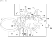
- Fig. 1 is a perspective view showing an overall configuration of an automatic analyzer.
- the automatic analyzer is a device that dispenses a specimen (sample) and a reagent in each of a plurality of reaction containers 2 and causes reactions in the reaction containers 2, and measures liquids obtained caused by reaction.
- the automatic analyzer includes, a reaction disk (incubator) 1, a reagent disk 9, a sample transport mechanism 17, reagent dispensing mechanisms 7, 8, sample dispensing mechanisms 11, 12, a cleaning mechanism 3, a spectrophotometer 4, stirring mechanisms 5, 6, a cleaning pump (not shown in the drawing), cleaning tanks 13, 14, 22, 23, 56, 57, and a control unit 21.
- the automatic analyzer further includes a display unit 51 and an input unit 52.
- the reaction containers 2 are arranged on the reaction disk 1 in a circumferential direction.
- the sample transport mechanism 17 that moves a sample rack 16 on which sample containers 15 (test tubes) are mounted is provided near the reaction disk 1.
- An inspection sample such as blood is stored in the sample container 15, and the sample container 15 is mounted on the sample rack 16 and is transported by the sample transport mechanism 17.
- Sample dispensing mechanisms 11, 12 that are rotatable and vertically movable are provided between the reaction disk 1 and the sample transport mechanism 17.
- the sample dispensing mechanisms 11, 12 include sample probes 11a, 12a, move while drawing an arc about rotary shafts of the sample dispensing mechanisms 11, 12, and dispense samples to the reaction containers 2 from the sample containers 15.
- the reagent disk 9 is capable of mounting a plurality of reagent bottles 10 on a circumference thereof.
- the reagent disk 9 is being kept cool.
- the reagent dispensing mechanisms 7, 8 are provided between the reaction disk 1 and the reagent disk 9 in a rotatable and vertically movable manner.
- the reagent dispensing mechanisms 7, 8 include reagent probes 7a, 8a, respectively.
- the reagent probes 7a, 8a moves while depicting an arc about a rotary shaft, accesses the reagent disk 9, and dispenses a reagent into the reaction container 2 from the reagent bottle 10.
- the cleaning mechanism 3 that cleans the reaction container 2 after the measurement is performed, stirring mechanisms 5, 6 that perform stirring of a mixed liquid (reaction liquid) of a reagent and sample in the reaction container 2, a light source (not shown in the drawing) that irradiates light to the mixed liquid (reaction liquid) in the reaction container 2, and measures the absorbance of the mixed liquid, and the spectrophotometer 4 are provided.
- the cleaning tanks 13, 14, 57, 56, 23, 22 are respectively provided on a movable range of the sample dispensing mechanisms 11, 12, the reagent dispensing mechanisms 7, 8, and the stirring mechanisms 5, 6.
- the respective mechanisms of the automatic analyzer are connected to the control unit 21 via an interface 50 (not shown in the drawing in Fig. 1 ), are controlled by the control unit 21.
- Analysis processing of the inspection sample by the automatic analyzer is, in general, performed in accordance with the following steps.
- a sample in the sample container 15 that is mounted on the sample rack 16 that is transported to a position near the reaction disk by the sample transport mechanism 17 is aspirated by the sample probe 11a of the sample dispensing mechanism 11, and the aspirated sample is discharged to the reaction container 2 on the reaction disk 1.
- a reagent used for an analysis is aspirated from the reagent bottle 10 on the reagent disk 9 by the reagent probe 7a of the reagent dispensing mechanism 7 or the reagent probe 8a of the reagent dispensing mechanism 8, and is discharged to the reaction container 2 into which the sample is dispensed previously.
- the mixed liquid of the sample and the reagent in the reaction container 2 is stirred by the stirring mechanism 5.
- the luminosity measured by the spectrophotometer 4 is transmitted to the control unit 21 via A/D converter and the interface 50.
- the control unit 21 performs an arithmetic operation for calculating, for example, the concentration or the like of a predetermined component among analysis items corresponding to a reagent based on absorbance of the mixed liquid (reaction liquid).
- the obtained measurement result is displayed on the display unit 51 (omitted in Fig. 1 ).
- the present invention is described by taking the automatic analyzer as an example, that obtains the concentration of the predetermined component using the spectrophotometer 4.
- the technique disclosed in the embodiment described later may be also used in an automatic immune analyzer or an automatic coagulation analyzer that measures a specimen using other photometers.
- the automatic analyzer has a liquid level detection function of detecting weather or not the probe is brought into contact with a liquid level based on a change in a capacitance of a tip end of the probe.
- a capacitance measurement unit that is provided on the probe for the liquid level detection, it is determined whether or not the probe is positionally displaced in a horizontal direction.
- the description is made in detail with respect to a method of correcting the position of the probe that determines the displacement of a movement trajectory of the probe based on a capacitance measured between the determination-use jigs fixedly or detachably mounted on the automatic analyzer, and corrects the position of the probe when necessary.
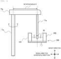
- Fig. 2 is a schematic view showing a one-axis dispensing mechanism having a rotation radius R, and a determination-use jig arranged in the automatic analyzer.
- the description is made by taking the reagent dispensing mechanism 7 described above as an example. Further, the present invention is equally applicable to other dispensing mechanisms, for example, the sample dispensing mechanisms 11, 12 and the reagent dispensing mechanism 8 described above.
- the reagent dispensing mechanism 7 includes: the reagent probe 7a that aspirates or discharges a liquid; an arm 7b that supports the reagent probe 7a; and a rotary shaft 7c that can rotate in a horizontal direction and can be displaced in a height direction.
- the reagent probe 7a is configured to be rotationally moveable in a horizontal plane and is vertically movable in a height direction corresponding to an operation of rotary shaft 7c by the control unit 21.
- the reagent probe 7a is configured to aspirate and discharge a liquid corresponding to an operation of a syringe not shown in the drawing by the control unit 21.
- the reagent probe 7a of the reagent dispensing mechanism 7 rotates and moves to a position above a vertical projection of the reagent bottle 10
- the reagent probe 7a is lowered and is immersed in a reagent in the reagent bottle 10, and aspirates the reagent.
- the reagent probe 7a of the reagent dispensing mechanism 7 moves to a position above vertical projection of the reaction container 2 by rotation after being elevated, the reagent probe 7a is lowered, and discharges the reagent in the reaction container 2.
- the reagent probe 7a includes a capacitance measurement unit 70 that measures a static capacitance between the reagent probe 7a and the surrounding thereof.
- the capacitance measurement unit 70 transmits a measured capacitance to the control unit 21 via the interface 50 (see Fig. 6 ).
- a determination jig 100 for determining the positional displacement of the reagent probe 7a is provided.
- the determination jig 100 includes a first member 101 and a second member 102 that are located on one side and the other side across a movement trajectory of the reagent probe 7a.
- the first member 101 and the second member 102 are formed using a conductive material, and are connected to a GND potential.
- the location where the determination jig 100 is provided is not limited to the cleaning tank provided that the location is within a movable range of the probe and is a structure that is not rotatable.
- the determination jig 100 can be provided in a thermostatic tank that keeps a temperature of the reaction container 2, a discard hole of the reaction container 2 or the like. Further, the determination jig 100 can be fixed in advance to a structure on the automatic analyzer or may be detachably mounted on the structure.
- the determination jig 100 is detachably mounted, for example, the determination jig 100 is attached before the determination of the positional displacement of the reagent probe 7a, and is removed after the determination of the positional displacement of the reagent probe 7a.
- Fig. 3 is a perspective view showing the structure of the determination jig 100.
- the determination jig 100 according to the embodiment is constituted of: a base 103 that forms a bottom surface; and the first member 101 and the second member 102 that are two members protruding upward from the base 103.
- the determination jig 100 is formed using a conductive material.
- the determination jig 100 may be formed using any other materials provided that capacitance changes in response to the presence or the non-presence of the first member 101 and the second member 102.
- the base 103, the first member 101 and the second member 102 may constitute the determination jig 100 in the form that these parts form an integral body, or may constitute the determination jig 100 in the form that these parts form separate bodies from each other.
- Fig. 4 is a top view showing a rotation trajectory of the probe
- Fig. 5 is a graph showing capacitance measured for each movement distance of the probe. Respective circumferential direction positions a to d in Fig. 4 correspond to movement distances A to D in Fig. 5 .
- the first member 101 and the second member 102 are provided at a predetermined interval in a movement direction of the reagent probe 7a.
- Fig. 5 with respect to capacitances measured by the capacitance measurement unit 70, two peaks appear along with the movement of the reagent probe 7a. Specifically, when the reagent probe 7a starts its rotation from a circumferential direction position a, the capacitance is gradually increased. When the reagent probe 7a reaches the circumferential direction position b that is a point at which the reagent probe 7a approaches closest to the first member 101, the capacitance takes a first peak value (P1).
- the capacitance is gradually decreased, thereafter, at an intermediate point between the circumferential direction position b and a circumferential direction position c, the capacitance is started to be increased again.
- the reagent probe 7a further rotates and reaches the circumferential direction position c that is a point at which the reagent probe 7a approaches closest to the second member 102, the capacitance takes a second peak value (P2) and, thereafter, the capacitance is gradually decreased.
- P2 second peak value
- the first member 101 is provided on an inner diameter side of the arcuate movement trajectory of the reagent probe 7a
- the second member 102 is provided on an outer diameter side of the arcuate movement trajectory of the reagent probe 7a.
- the position of the reagent probe 7a is normal, it is set in advance that the reagent probe 7a passes an intermediate position in the radial direction between an outer diameter side end of the first member 101 and an inner diameter side end of the second member 102.
- the capacitance measured by the capacitance measurement unit 70 takes a waveform indicated by a solid line in Fig. 5 . That is, the first peak value (P1) caused by the first member 101 and the second peak value (P2) caused by the second member 102 become substantially the same.
- the first peak value (P1) becomes larger than the second peak value (P2) as indicated by a dotted line in Fig. 5 .
- the second peak value (P2) becomes larger than the first peak value (P1) as indicated by a broken line in Fig. 5 .
- the positional displacement of the reagent probe 7a in the radial direction by calculating the first peak value (P1) that appears first and the second peak value (P2) that appears next respectively and by making a comparison which peak value is larger between the first peak value (P1) and the second peak value (P2).
- the positional displacement of the reagent probe 7a is determined by performing a relative comparison between two peak values, the determination accuracy becomes high compared to a case where the determination is performed by comparing either one peak value (absolute value) and a reference value.
- a movement amount (rotation angle D2) or a movement time from the rotation start position (the circumferential direction position a in Fig. 4 ) to the position that corresponds to the second peak value (P2) (the circumferential direction position c in Fig. 4 ) may be used.
- the circumferential direction position that becomes the reference is not limited to the rotation start position, and may be other position (for example, the circumferential direction position d in Fig. 4 ).
- the first member 101 and the second member 102 have a shape of protruding toward the movement trajectory of the reagent probe 7a. Accordingly, when a distance between a tip end of the protruding portion and the reagent probe 7a becomes a shortest distance, capacitance is sharply increased, and when the reagent probe 7a passes the shortest distance position, the capacitance is sharply decreased. As a result, the peak of the capacitance measured by the capacitance measurement unit 70 becomes apparent and hence, the determination accuracy of positional displacement is enhanced.
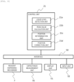
- Fig. 6 is a functional block diagram of the automatic analyzer. In Fig. 6 , functions other than calculations relating to the capacitance are omitted.
- the control unit 21 is a computer that includes a processor and a memory. As shown in Fig. 6 , the control unit 21 includes a liquid level detection unit 21a, a peak value calculation unit 21b, a position determination unit 21c, and a position correction unit 21d.
- the liquid level detection unit 21a, the peak value calculation unit 21b, the position determination unit 21c, and the position correction unit 21d are functions that are realized by executing programs stored in the memory by the processor.
- the liquid level detection unit 21a detects whether or not the probe reaches a liquid level based on a change in capacitance measured by the capacitance measurement unit 70 when the dispensing mechanism is lowered.
- the peak value calculation unit 21b calculates peak values of capacitances caused by the first member 101 and the second member 102 respectively.
- the position determination unit 21c determines the position of the probe in the radial direction by comparing the first peak value (P1) and the second peak value (P2).
- the position determination unit 21c may determines the circumferential direction position of the probe based on whether or not a movement amount or a movement time from the reference position of the probe to the position corresponding to the first peak value (P1) or the second peak value (P2) is within a predetermined range.
- the display unit 51 and the input unit 52 are also connected besides a dispensing mechanism (the reagent dispensing mechanism 7 as an example in this embodiment) and the capacitance measurement unit 70.
- the display unit 51 is a unit that displays an alarm or the like when a result of the position determination is abnormal, and is a display, for example.
- the input unit 52 is a unit that is used when a user inputs operation information or the like, and is keyboard, for example.
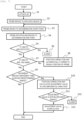
- Fig. 7 is a flowchart relating to determination and correction of a position of the probe.
- the description is made with respect to an automatic adjustment function that also performs the correction of the position of the probe when it is determined that the positional displacement exists.
- the processing may be adopted where the automatic analyzer performs steps up to outputting of an alarm or the like based on the determination of the positional displacement of the probe, and an operation in charge of maintenance performs the positional correction of the probe.
- timing at which the automatic adjustment function is performed a point of time that the probe or the thermostatic tank is exchanged, a point of time at which the automatic analyzer is initialized, or a point of time that the maintenance of the automatic analyzer is performed is named.
- the control unit 21 outputs a message to the display unit 51 that prompts attaching of the determination jig 100 to a predetermined place of the automatic analyzer (step S1).
- the step S1 is unnecessary.
- the control unit 21 drives the reagent dispensing mechanism 7 in a height direction so as to move the reagent probe 7a to a predetermined height for positional determination (step S2). Then, the control unit 21 drives the reagent dispensing mechanism 7 in a horizontal direction so that the reagent probe 7a moves to a determination start point (step S3) .
- the reagent probe 7a starts its rotation from the determination start point.
- the reagent probe 7a passes a position near the first member 101 and, thereafter, passes a position near the second member 102, and reaches a determination end point (step S4).
- the peak value calculation unit 21b of the control unit 21 calculates the first peak value (P1) and the second peak value (P2), and calculates a movement amount or the movement time from the determination start point to the position that corresponds to the first peak value (P1) (step S5).
- step S5 In a case where the peak values, the movement amount or the movement time cannot be calculated in step S5, an alarm or the like that prompts the confirmation whether the determination jig 100 is accurately mounted is outputted via the display unit 51 (step S6).
- step S6 the position determination unit 21c determines whether or not the first peak value (P1) and the second peak value (P2) are substantially the same (step S7).
- the reagent probe 7a is positionally displaced in a radial direction. That is, the position determination unit 21c determines that the reagent probe 7a is displaced toward an inner diameter side in a case where P1 is larger than P2, and determines that the reagent probe 7a is displaced toward an outer diameter side in a case where P2 is larger than P1.
- the position correction unit 21d corrects a position of the reagent probe 7a in a radial direction corresponding to a determination result of the reagent probe 7a made by the position determination unit 21c (step S8).
- a message that prompts a maintenance user to perform the positional correction may be outputted via the display unit 51.
- the processing returns to the step S4.
- the position of the reagent probe 7a in a radial direction is normal. Accordingly, in this case, the determination of the position of the reagent probe 7a in a circumferential direction is made. In such determination, the position determination unit 21c determines whether or not the movement amount or the movement time calculated in step S6 is within a predetermined range (step S9).
- the reagent probe 7a is positionally displaced in the circumferential direction. Accordingly, the position correction unit 21d calculates a differential from a designed value as an adjustment value in the circumferential direction (step S10). Next, the position correction unit 21d determines whether or not the adjustment value is within a specified range (step S11) .
- step S11 In a case where the adjustment value is not within the specified range in step S11, an alarm is outputted via the display unit 51 (step S12). On the other hand, in step S11, in a case where it is determined that the adjustment value is within the specified range, the adjustment value is reflected on the automatic analyzer (step S13), and the automatic adjustment function is finished.
- the positional displacement of the probe in the radial direction and in the circumferential direction is determined and the position is corrected when necessary. Accordingly, an operation of performing aspirating or discharging a liquid at an appropriate probe position is guaranteed and hence, the reliability of the automatic analyzer is enhanced.
- the probe draws an arcuate trajectory by the rotation of the dispensing mechanism having one shaft.
- the dispending mechanism may be of a type where the probe rotates about a plurality of shafts or of a type where the probe moves linearly.
- the first member 101 and the second member 102 are not limited to a horizontal cross-sectional shape as shown in Fig. 4 , and the first member 101 and the second member 102 may have a circular horizontal cross-sectional shape or a polygonal horizontal cross-sectional shape.
- a profile (inclination) in a height direction of a portion that faces the movement trajectory may be set so as to follow a profile (inclination) in a height direction of the capacitance measurement unit 70 at the tip end of the probe.
- first member 101 and the second member 102 may be formed in a recessed shape with respect to the base 103 instead of forming the first member 101 and the second member 102 in a protruding shape with respect to the base 103 as shown in Fig. 3 .
- the capacitance is decreased. Accordingly, the position of the probe can be determined by calculating minimum values of the capacitances caused by the respective members.
- the members attached to the determination jig 100 are not limited to two members consisting of the first member and the second member, and may be three or more members. In a case where the positional displacement of the probe in the radial direction is not determined and only the positional displacement of the probe in the circumferential direction is determined, it is unnecessary for the determination jig 100 to have a plurality of members that are formed in a protruding shape or a recessed shape. It is sufficient for the determination jig 100 to have only a single member formed in a protruding shape or a recessed shape following the movement trajectory of the probe.
Landscapes
- Physics & Mathematics (AREA)
- Engineering & Computer Science (AREA)
- General Physics & Mathematics (AREA)
- Power Engineering (AREA)
- Fluid Mechanics (AREA)
- Thermal Sciences (AREA)
- Electromagnetism (AREA)
- Health & Medical Sciences (AREA)
- Life Sciences & Earth Sciences (AREA)
- Chemical & Material Sciences (AREA)
- Analytical Chemistry (AREA)
- Biochemistry (AREA)
- General Health & Medical Sciences (AREA)
- Immunology (AREA)
- Pathology (AREA)
- Signal Processing (AREA)
- Automatic Analysis And Handling Materials Therefor (AREA)
Abstract
Description
- The present invention relates to an automatic analyzer and a control method thereof.
- An automatic analyzer used in a clinical inspection includes a probe for dispensing a reagent or a sample. To enhance the dispensing accuracy and the cleaning efficiency of the probe, it is necessary to adjust the probe such that the probe stops at the center of a dispensing position or a cleaning position. For example,
Patent Literature 1 discloses a technique that detects the displacement of the lowered position of a probe by diverting a capacitance detection mechanism that is provided to an automatic analyzer and is used for performing a liquid level detection function. - Patent Literature 1:
Japanese Unexamined Patent Application Publication No. 2011-033551 - However, in the technique described in
Patent Literature 1, although the positional displacement of the probe in a height direction can be detected, it is difficult for the technique to detect the positional displacement of the probe in a horizontal direction.
It is an object of the present invention to provide an automatic analyzer that can determine the positional displacement of a probe in a horizontal direction and a control method of the automatic analyzer by making use of a liquid level detection function in a capacitance in the automatic analyzer. - To achieve the above-mentioned object, an automatic analyzer according to the present invention includes: a dispensing mechanism capable of driving a probe that aspirates or discharges a liquid in a horizontal direction and a height direction; a capacitance measurement unit provided on the probe and configured to measure capacitance between the probe and a surrounding; and a control unit configured to control the dispensing mechanism and the capacitance measurement unit, in which the control unit includes: a liquid level detection unit configured to detect a liquid level of the liquid based on the capacitance measured by the capacitance measurement unit; a peak value calculation unit configured to calculate respective peak values of capacitances caused by a first member and a second member when the dispensing mechanism is driven in the horizontal direction, the first member and the second member being located on one side and the other side across a movement trajectory of the probe and provided at a predetermined interval in a movement direction of the probe; and a position determination unit configured to determine a horizontal position of the probe by comparing a first peak value caused by the first member and a second peak value caused by the second member.
- In a control method of an automatic analyzer according to the present invention, a control unit includes the steps of: detecting a liquid level of the liquid based on the capacitance measured by the capacitance measurement unit; calculating respective peak values of capacitances caused by a first member and a second member when the dispensing mechanism is driven in the horizontal direction, the first member and the second member being located on one side and the other side across a movement trajectory of the probe and provided at a predetermined interval in a movement direction of the probe; and determining a horizontal position of the probe by comparing a first peak value caused by the first member and a second peak value caused by the second member. Advantageous Effects of Invention
- According to the present invention, it is possible to provide an automatic analyzer and a control method thereof that can determine the positional displacement of a probe in a horizontal direction.
-
- [
FIG. 1] FIG. 1 is a perspective view showing an overall configuration of an automatic analyzer. - [
FIG. 2] FIG. 2 is a schematic view showing a dispensing mechanism and a determination jig. - [
FIG. 3] FIG. 3 is a perspective view showing a structure of the determination jig. - [
FIG. 4] FIG. 4 is a top view showing a rotation trajectory of a probe and the determination jig. - [
FIG. 5] FIG. 5 is a graph showing a capacitance measured for each movement distance of the probe. - [
FIG. 6] FIG. 6 is a functional block diagram of the automatic analyzer. - [
FIG. 7] FIG. 7 is a flowchart relating to determination and correction of a position of the probe. Description of Embodiments -
Fig. 1 is a perspective view showing an overall configuration of an automatic analyzer. The automatic analyzer is a device that dispenses a specimen (sample) and a reagent in each of a plurality ofreaction containers 2 and causes reactions in thereaction containers 2, and measures liquids obtained caused by reaction. The automatic analyzer includes, a reaction disk (incubator) 1, areagent disk 9, asample transport mechanism 17,reagent dispensing mechanisms sample dispensing mechanisms 11, 12, acleaning mechanism 3, aspectrophotometer 4,stirring mechanisms cleaning tanks control unit 21. Although omitted inFig. 1 , the automatic analyzer further includes adisplay unit 51 and aninput unit 52. - The
reaction containers 2 are arranged on thereaction disk 1 in a circumferential direction. Thesample transport mechanism 17 that moves asample rack 16 on which sample containers 15 (test tubes) are mounted is provided near thereaction disk 1. An inspection sample such as blood is stored in the sample container 15, and the sample container 15 is mounted on thesample rack 16 and is transported by thesample transport mechanism 17.Sample dispensing mechanisms 11, 12 that are rotatable and vertically movable are provided between thereaction disk 1 and thesample transport mechanism 17. Thesample dispensing mechanisms 11, 12 includesample probes sample dispensing mechanisms 11, 12, and dispense samples to thereaction containers 2 from the sample containers 15. - The
reagent disk 9 is capable of mounting a plurality ofreagent bottles 10 on a circumference thereof. Thereagent disk 9 is being kept cool. Thereagent dispensing mechanisms reaction disk 1 and thereagent disk 9 in a rotatable and vertically movable manner. Thereagent dispensing mechanisms reagent probes reagent probes reagent disk 9, and dispenses a reagent into thereaction container 2 from thereagent bottle 10. - Around the
reaction dick 1, thecleaning mechanism 3 that cleans thereaction container 2 after the measurement is performed, stirringmechanisms reaction container 2, a light source (not shown in the drawing) that irradiates light to the mixed liquid (reaction liquid) in thereaction container 2, and measures the absorbance of the mixed liquid, and thespectrophotometer 4 are provided. Thecleaning tanks sample dispensing mechanisms 11, 12, thereagent dispensing mechanisms stirring mechanisms control unit 21 via an interface 50 (not shown in the drawing inFig. 1 ), are controlled by thecontrol unit 21. - Analysis processing of the inspection sample by the automatic analyzer is, in general, performed in accordance with the following steps. First, a sample in the sample container 15 that is mounted on the
sample rack 16 that is transported to a position near the reaction disk by thesample transport mechanism 17 is aspirated by thesample probe 11a of the sample dispensing mechanism 11, and the aspirated sample is discharged to thereaction container 2 on thereaction disk 1. Next, a reagent used for an analysis is aspirated from thereagent bottle 10 on thereagent disk 9 by thereagent probe 7a of thereagent dispensing mechanism 7 or thereagent probe 8a of thereagent dispensing mechanism 8, and is discharged to thereaction container 2 into which the sample is dispensed previously. Subsequently, the mixed liquid of the sample and the reagent in thereaction container 2 is stirred by thestirring mechanism 5. - Then, light irradiated from the light source is made to transmit the
reaction container 2 filled with the mixed liquid, and luminosity of transmitted light is measured by thespectrophotometer 4. The luminosity measured by thespectrophotometer 4 is transmitted to thecontrol unit 21 via A/D converter and theinterface 50. Thecontrol unit 21 performs an arithmetic operation for calculating, for example, the concentration or the like of a predetermined component among analysis items corresponding to a reagent based on absorbance of the mixed liquid (reaction liquid). The obtained measurement result is displayed on the display unit 51 (omitted inFig. 1 ). The present invention is described by taking the automatic analyzer as an example, that obtains the concentration of the predetermined component using thespectrophotometer 4. The technique disclosed in the embodiment described later may be also used in an automatic immune analyzer or an automatic coagulation analyzer that measures a specimen using other photometers. - In the above-mentioned configuration, the automatic analyzer has a liquid level detection function of detecting weather or not the probe is brought into contact with a liquid level based on a change in a capacitance of a tip end of the probe. In this embodiment, by diverting a capacitance measurement unit that is provided on the probe for the liquid level detection, it is determined whether or not the probe is positionally displaced in a horizontal direction. Hereinafter, the description is made in detail with respect to a method of correcting the position of the probe that determines the displacement of a movement trajectory of the probe based on a capacitance measured between the determination-use jigs fixedly or detachably mounted on the automatic analyzer, and corrects the position of the probe when necessary.
-
Fig. 2 is a schematic view showing a one-axis dispensing mechanism having a rotation radius R, and a determination-use jig arranged in the automatic analyzer. Hereinafter, the description is made by taking thereagent dispensing mechanism 7 described above as an example. Further, the present invention is equally applicable to other dispensing mechanisms, for example, thesample dispensing mechanisms 11, 12 and thereagent dispensing mechanism 8 described above. - As shown in
Fig. 2 , thereagent dispensing mechanism 7 includes: thereagent probe 7a that aspirates or discharges a liquid; anarm 7b that supports thereagent probe 7a; and arotary shaft 7c that can rotate in a horizontal direction and can be displaced in a height direction. Thereagent probe 7a is configured to be rotationally moveable in a horizontal plane and is vertically movable in a height direction corresponding to an operation ofrotary shaft 7c by thecontrol unit 21. Thereagent probe 7a is configured to aspirate and discharge a liquid corresponding to an operation of a syringe not shown in the drawing by thecontrol unit 21. For example, when thereagent probe 7a of thereagent dispensing mechanism 7 rotates and moves to a position above a vertical projection of thereagent bottle 10, thereagent probe 7a is lowered and is immersed in a reagent in thereagent bottle 10, and aspirates the reagent. Next, when thereagent probe 7a of thereagent dispensing mechanism 7 moves to a position above vertical projection of thereaction container 2 by rotation after being elevated, thereagent probe 7a is lowered, and discharges the reagent in thereaction container 2. - Further, the
reagent probe 7a includes acapacitance measurement unit 70 that measures a static capacitance between thereagent probe 7a and the surrounding thereof. Thecapacitance measurement unit 70 transmits a measured capacitance to thecontrol unit 21 via the interface 50 (seeFig. 6 ). - Further, in a place that corresponds to a movement trajectory of the
reagent probe 7a in a horizontal direction, for example, acleaning tank 57 that cleans thereagent probe 7a, adetermination jig 100 for determining the positional displacement of thereagent probe 7a is provided. Thedetermination jig 100 includes afirst member 101 and asecond member 102 that are located on one side and the other side across a movement trajectory of thereagent probe 7a. Thefirst member 101 and thesecond member 102 are formed using a conductive material, and are connected to a GND potential. - The location where the
determination jig 100 is provided is not limited to the cleaning tank provided that the location is within a movable range of the probe and is a structure that is not rotatable. For example, in case of the sample probes 11a, 12a, thedetermination jig 100 can be provided in a thermostatic tank that keeps a temperature of thereaction container 2, a discard hole of thereaction container 2 or the like. Further, thedetermination jig 100 can be fixed in advance to a structure on the automatic analyzer or may be detachably mounted on the structure. In the case where thedetermination jig 100 is detachably mounted, for example, thedetermination jig 100 is attached before the determination of the positional displacement of thereagent probe 7a, and is removed after the determination of the positional displacement of thereagent probe 7a. -
Fig. 3 is a perspective view showing the structure of thedetermination jig 100. As shown inFig. 3 , thedetermination jig 100 according to the embodiment is constituted of: a base 103 that forms a bottom surface; and thefirst member 101 and thesecond member 102 that are two members protruding upward from thebase 103. As described previously, it is desirable that thedetermination jig 100 is formed using a conductive material. However, thedetermination jig 100 may be formed using any other materials provided that capacitance changes in response to the presence or the non-presence of thefirst member 101 and thesecond member 102. Thebase 103, thefirst member 101 and thesecond member 102 may constitute thedetermination jig 100 in the form that these parts form an integral body, or may constitute thedetermination jig 100 in the form that these parts form separate bodies from each other. - Next, how the movement trajectory and a capacitance change between a case where the
reagent probe 7a is positioned normally and a case where thereagent probe 7a is positioned in a displaced manner is described with reference toFig. 4 andFig. 5 .Fig. 4 is a top view showing a rotation trajectory of the probe, and a determination jig.Fig. 5 is a graph showing capacitance measured for each movement distance of the probe. Respective circumferential direction positions a to d inFig. 4 correspond to movement distances A to D inFig. 5 . - As shown in
Fig. 4 , thefirst member 101 and thesecond member 102 are provided at a predetermined interval in a movement direction of thereagent probe 7a. With such a configuration, as shown inFig. 5 , with respect to capacitances measured by thecapacitance measurement unit 70, two peaks appear along with the movement of thereagent probe 7a. Specifically, when thereagent probe 7a starts its rotation from a circumferential direction position a, the capacitance is gradually increased. When thereagent probe 7a reaches the circumferential direction position b that is a point at which thereagent probe 7a approaches closest to thefirst member 101, the capacitance takes a first peak value (P1). When thereagent probe 7a further rotates, the capacitance is gradually decreased, thereafter, at an intermediate point between the circumferential direction position b and a circumferential direction position c, the capacitance is started to be increased again. When thereagent probe 7a further rotates and reaches the circumferential direction position c that is a point at which thereagent probe 7a approaches closest to thesecond member 102, the capacitance takes a second peak value (P2) and, thereafter, the capacitance is gradually decreased. With respect to the movement direction of thereagent probe 7a, when a distance between thefirst member 101 and thesecond member 102 is set too short, two peaks overlap with each other and it is difficult to distinguish two peaks from each other. Accordingly, it is desirable that the distance between the center positions of the respective members be 10 mm or more. - The
first member 101 is provided on an inner diameter side of the arcuate movement trajectory of thereagent probe 7a, and thesecond member 102 is provided on an outer diameter side of the arcuate movement trajectory of thereagent probe 7a. In a case where the position of thereagent probe 7a is normal, it is set in advance that thereagent probe 7a passes an intermediate position in the radial direction between an outer diameter side end of thefirst member 101 and an inner diameter side end of thesecond member 102. Accordingly, in a case where thereagent probe 7a is provided at the normal position and the movement trajectory takes a trajectory T0 as shown inFig. 4 , the capacitance measured by thecapacitance measurement unit 70 takes a waveform indicated by a solid line inFig. 5 . That is, the first peak value (P1) caused by thefirst member 101 and the second peak value (P2) caused by thesecond member 102 become substantially the same. - However, in a case where the
reagent probe 7a is positionally displaced toward an inner diameter side so that the movement trajectory takes a trajectory expressed by T1 inFig. 4 , the first peak value (P1) becomes larger than the second peak value (P2) as indicated by a dotted line inFig. 5 . On the other hand, in a case where thereagent probe 7a is positionally displaced toward an outer diameter side so that the movement trajectory takes a trajectory expressed by T2 inFig. 4 , the second peak value (P2) becomes larger than the first peak value (P1) as indicated by a broken line inFig. 5 . Accordingly, it is possible to determine the positional displacement of thereagent probe 7a in the radial direction by calculating the first peak value (P1) that appears first and the second peak value (P2) that appears next respectively and by making a comparison which peak value is larger between the first peak value (P1) and the second peak value (P2). In this manner, the positional displacement of thereagent probe 7a is determined by performing a relative comparison between two peak values, the determination accuracy becomes high compared to a case where the determination is performed by comparing either one peak value (absolute value) and a reference value. - Further, it is also possible to determine the positional displacement of the
reagent probe 7a in the circumferential direction based on whether a movement amount (rotation angle D1) or a movement time from a rotation start position (the circumferential direction position a inFig. 4 ) to the position that corresponds to the first peak value (P1) (the circumferential direction position b inFig. 4 ) is within a predetermined range. In the positional displacement determination of thereagent probe 7a in the circumferential direction, a movement amount (rotation angle D2) or a movement time from the rotation start position (the circumferential direction position a inFig. 4 ) to the position that corresponds to the second peak value (P2) (the circumferential direction position c inFig. 4 ) may be used. The circumferential direction position that becomes the reference is not limited to the rotation start position, and may be other position (for example, the circumferential direction position d inFig. 4 ). - In this embodiment, the
first member 101 and thesecond member 102 have a shape of protruding toward the movement trajectory of thereagent probe 7a. Accordingly, when a distance between a tip end of the protruding portion and thereagent probe 7a becomes a shortest distance, capacitance is sharply increased, and when thereagent probe 7a passes the shortest distance position, the capacitance is sharply decreased. As a result, the peak of the capacitance measured by thecapacitance measurement unit 70 becomes apparent and hence, the determination accuracy of positional displacement is enhanced. -
Fig. 6 is a functional block diagram of the automatic analyzer. InFig. 6 , functions other than calculations relating to the capacitance are omitted. - The
control unit 21 is a computer that includes a processor and a memory. As shown inFig. 6 , thecontrol unit 21 includes a liquidlevel detection unit 21a, a peakvalue calculation unit 21b, aposition determination unit 21c, and aposition correction unit 21d. The liquidlevel detection unit 21a, the peakvalue calculation unit 21b, theposition determination unit 21c, and theposition correction unit 21d are functions that are realized by executing programs stored in the memory by the processor. - The liquid
level detection unit 21a detects whether or not the probe reaches a liquid level based on a change in capacitance measured by thecapacitance measurement unit 70 when the dispensing mechanism is lowered. The peakvalue calculation unit 21b calculates peak values of capacitances caused by thefirst member 101 and thesecond member 102 respectively. Theposition determination unit 21c determines the position of the probe in the radial direction by comparing the first peak value (P1) and the second peak value (P2). Theposition determination unit 21c may determines the circumferential direction position of the probe based on whether or not a movement amount or a movement time from the reference position of the probe to the position corresponding to the first peak value (P1) or the second peak value (P2) is within a predetermined range. - To the
control unit 21, via theinterface 50, thedisplay unit 51 and theinput unit 52 are also connected besides a dispensing mechanism (thereagent dispensing mechanism 7 as an example in this embodiment) and thecapacitance measurement unit 70. Thedisplay unit 51 is a unit that displays an alarm or the like when a result of the position determination is abnormal, and is a display, for example. Theinput unit 52 is a unit that is used when a user inputs operation information or the like, and is keyboard, for example. - Next, the flow of processing of determining the displacement of the movement trajectory of the probe and correcting the position of the probe is described with reference to
Fig. 7. Fig. 7 is a flowchart relating to determination and correction of a position of the probe. Hereinafter, the description is made with respect to an automatic adjustment function that also performs the correction of the position of the probe when it is determined that the positional displacement exists. Also, the processing may be adopted where the automatic analyzer performs steps up to outputting of an alarm or the like based on the determination of the positional displacement of the probe, and an operation in charge of maintenance performs the positional correction of the probe. As timing at which the automatic adjustment function is performed, a point of time that the probe or the thermostatic tank is exchanged, a point of time at which the automatic analyzer is initialized, or a point of time that the maintenance of the automatic analyzer is performed is named. - First, when a maintenance operator operates a button for performing an automatic adjustment function using the
input unit 52, the automatic adjustment function starts. Then, thecontrol unit 21 outputs a message to thedisplay unit 51 that prompts attaching of thedetermination jig 100 to a predetermined place of the automatic analyzer (step S1). In a case where thedetermination jig 100 is fixed to thecleaning tank 57 or the like of the automatic analyzer in advance, the step S1 is unnecessary. - When the
determination jig 100 is mounted and a confirmation button is operated by a maintenance operator, thecontrol unit 21 drives thereagent dispensing mechanism 7 in a height direction so as to move thereagent probe 7a to a predetermined height for positional determination (step S2). Then, thecontrol unit 21 drives thereagent dispensing mechanism 7 in a horizontal direction so that thereagent probe 7a moves to a determination start point (step S3) . - Next, the
reagent probe 7a starts its rotation from the determination start point. First, thereagent probe 7a passes a position near thefirst member 101 and, thereafter, passes a position near thesecond member 102, and reaches a determination end point (step S4). At this point of time, the peakvalue calculation unit 21b of thecontrol unit 21 calculates the first peak value (P1) and the second peak value (P2), and calculates a movement amount or the movement time from the determination start point to the position that corresponds to the first peak value (P1) (step S5). - In a case where the peak values, the movement amount or the movement time cannot be calculated in step S5, an alarm or the like that prompts the confirmation whether the
determination jig 100 is accurately mounted is outputted via the display unit 51 (step S6). On the other hand, in a case where the peak values and the like are calculated in step S5, theposition determination unit 21c determines whether or not the first peak value (P1) and the second peak value (P2) are substantially the same (step S7). - In a case where it is determined that the first peak value (P1) and the second peak value (P2) are not the same in step S7, the
reagent probe 7a is positionally displaced in a radial direction. That is, theposition determination unit 21c determines that thereagent probe 7a is displaced toward an inner diameter side in a case where P1 is larger than P2, and determines that thereagent probe 7a is displaced toward an outer diameter side in a case where P2 is larger than P1. Theposition correction unit 21d corrects a position of thereagent probe 7a in a radial direction corresponding to a determination result of thereagent probe 7a made by theposition determination unit 21c (step S8). In a case where thereagent dispensing mechanism 7 does not include an actuator that can move thereagent probe 7a in the radial direction, a message that prompts a maintenance user to perform the positional correction may be outputted via thedisplay unit 51. When the position correction is completed, the processing returns to the step S4. On the other hand, in a case where it is determined that P1 and P2 are the same in step S7, the position of thereagent probe 7a in a radial direction is normal. Accordingly, in this case, the determination of the position of thereagent probe 7a in a circumferential direction is made. In such determination, theposition determination unit 21c determines whether or not the movement amount or the movement time calculated in step S6 is within a predetermined range (step S9). - In a case where it is determined that the movement amount or the movement time calculated in step S6 is not within the predetermined range in step S9, the
reagent probe 7a is positionally displaced in the circumferential direction. Accordingly, theposition correction unit 21d calculates a differential from a designed value as an adjustment value in the circumferential direction (step S10). Next, theposition correction unit 21d determines whether or not the adjustment value is within a specified range (step S11) . - In a case where the adjustment value is not within the specified range in step S11, an alarm is outputted via the display unit 51 (step S12). On the other hand, in step S11, in a case where it is determined that the adjustment value is within the specified range, the adjustment value is reflected on the automatic analyzer (step S13), and the automatic adjustment function is finished.
- As has been described heretofore, in this embodiment, the positional displacement of the probe in the radial direction and in the circumferential direction is determined and the position is corrected when necessary. Accordingly, an operation of performing aspirating or discharging a liquid at an appropriate probe position is guaranteed and hence, the reliability of the automatic analyzer is enhanced.
- The present invention is not limited to the above-mentioned embodiment, and various modifications are conceivable. For example, in the above-mentioned embodiment, the probe draws an arcuate trajectory by the rotation of the dispensing mechanism having one shaft. However, provided that the dispensing mechanism can be driven in the horizontal direction, the dispending mechanism may be of a type where the probe rotates about a plurality of shafts or of a type where the probe moves linearly.
- Particularly, the following modifications are considered with respect to the
determination jig 100. - For example, the
first member 101 and thesecond member 102 are not limited to a horizontal cross-sectional shape as shown inFig. 4 , and thefirst member 101 and thesecond member 102 may have a circular horizontal cross-sectional shape or a polygonal horizontal cross-sectional shape. With respect to thefirst member 101 and thesecond member 102, a profile (inclination) in a height direction of a portion that faces the movement trajectory may be set so as to follow a profile (inclination) in a height direction of thecapacitance measurement unit 70 at the tip end of the probe. With such a configuration, an increase range of capacitance when each member and the probe are made to approach each other can enlarged and hence, an S/N ratio may be enhanced. - Further, the
first member 101 and thesecond member 102 may be formed in a recessed shape with respect to the base 103 instead of forming thefirst member 101 and thesecond member 102 in a protruding shape with respect to the base 103 as shown inFig. 3 . In this case, when the probe approaches the first member and the second member, the capacitance is decreased. Accordingly, the position of the probe can be determined by calculating minimum values of the capacitances caused by the respective members. - The members attached to the
determination jig 100 are not limited to two members consisting of the first member and the second member, and may be three or more members. In a case where the positional displacement of the probe in the radial direction is not determined and only the positional displacement of the probe in the circumferential direction is determined, it is unnecessary for thedetermination jig 100 to have a plurality of members that are formed in a protruding shape or a recessed shape. It is sufficient for thedetermination jig 100 to have only a single member formed in a protruding shape or a recessed shape following the movement trajectory of the probe. -
- 2: reaction container
- 3: cleaning mechanism
- 4: spectrophotometer
- 5, 6: stirring mechanism
- 7, 8: reagent dispensing mechanism
- 7a, 8a: reagent probe
- 9: reagent disk
- 10: reagent bottle
- 11, 12: sample dispensing mechanism
- 11a, 12a: sample probe
- 13, 14, 22, 23, 56, 57: cleaning tank
- 15: sample container
- 16: sample rack
- 17: sample transport mechanism
- 21: control unit
- 21a: liquid level detection unit
- 21b: peak value calculation unit
- 21c: position determination unit
- 21d: position correction unit
- 50: interface
- 51: display unit
- 52: input unit
- 70: capacitance measurement unit
- 100: determination jig
- 101: first member
- 102: second member
- 103: base
Claims (9)
- An automatic analyzer comprising:a dispensing mechanism capable of driving a probe that aspirates or discharges a liquid in a horizontal direction and a height direction;a capacitance measurement unit provided on the probe and configured to measure a capacitance between the probe and a surrounding; anda control unit configured to control the dispensing mechanism and the capacitance measurement unit, whereinthe control unit includes:a liquid level detection unit configured to detect a liquid level of the liquid based on the capacitance measured by the capacitance measurement unit;a peak value calculation unit configured to calculate respective peak values of capacitances caused by a first member and a second member when the dispensing mechanism is driven in the horizontal direction, the first member and the second member being located on one side and the other side across a movement trajectory of the probe and provided at a predetermined interval in a movement direction of the probe; anda position determination unit configured to determine a horizontal position of the probe by comparing a first peak value caused by the first member and a second peak value caused by the second member.
- The automatic analyzer according to claim 1, whereinthe first member is provided on an inner diameter side of the circular movement trajectory of the probe, and the second member is provided on an outer diameter side of the circular movement trajectory of the probe, andthe position determination unit determines that the probe is displaced toward the inner diameter side when the first peak value is larger than the second peak value, and determines that the probe is displaced toward the outer diameter side when the second peak value is larger than the first peak value.
- The automatic analyzer according to claim 2, wherein
the position determination unit determines that the probe is displaced in a circumferential direction when a movement amount or movement time for the probe to reach a position corresponding to the first peak value or the second peak value from a reference position is out of a predetermined range. - The automatic analyzer according to claim 3, wherein
the control unit further includes a position correction unit configured to correct a position of the probe when a displacement of the probe is determined. - The automatic analyzer according to claim 2, wherein
the first member and the second member have a shape of protruding toward the movement trajectory of the probe. - The automatic analyzer according to claim 1, wherein
the first member and the second member are attached before the determination of the horizontal position of the probe, and are removed after the determination of the horizontal position of the probe. - The automatic analyzer according to claim 1, further comprising:a cleaning tank configured to clean the probe, whereinthe first member and the second member are fixed to the cleaning tank.
- An automatic analyzer comprising:a dispensing mechanism capable of driving a probe that aspirates or discharges a liquid in a horizontal direction and a height direction;a capacitance measurement unit provided on the probe and configured to measure a capacitance between the probe and a surrounding; anda control unit configured to control the dispensing mechanism and the capacitance measurement unit, whereinthe control unit includes:a liquid level detection unit configured to detect a liquid level of the liquid based on the capacitance measured by the capacitance measurement unit;a peak value calculation unit configured to calculate a peak value of a capacitance caused by a member provided along a movement trajectory of the probe when the dispensing mechanism is driven in the horizontal direction; anda position determination unit configured to determine that the probe is displaced in a circumferential direction when a movement amount or movement time for the probe to reach a position corresponding to the peak value from a reference position is out of a predetermined range.
- A control method of an automatic analyzer, the automatic analyzer including a dispensing mechanism capable of driving a probe that aspirates or discharges a liquid in a horizontal direction and a height direction, a capacitance measurement unit provided on the probe and configured to measure a capacitance between the probe and a surrounding, and a control unit configured to control the dispensing mechanism and the capacitance measurement unit, the method causing the control unit to:detect a liquid level of the liquid based on the capacitance measured by the capacitance measurement unit;calculate respective peak values of capacitances caused by a first member and a second member when the dispensing mechanism is driven in the horizontal direction, the first member and the second member being located on one side and the other side across a movement trajectory of the probe and provided at a predetermined interval in a movement direction of the probe; anddetermine a horizontal position of the probe by comparing a first peak value caused by the first member and a second peak value caused by the second member.
Applications Claiming Priority (2)
| Application Number | Priority Date | Filing Date | Title |
|---|---|---|---|
| JP2021210778 | 2021-12-24 | ||
| PCT/JP2022/044310 WO2023120088A1 (en) | 2021-12-24 | 2022-12-01 | Automatic analysis device and control method for same |
Publications (2)
| Publication Number | Publication Date |
|---|---|
| EP4455680A1 true EP4455680A1 (en) | 2024-10-30 |
| EP4455680A4 EP4455680A4 (en) | 2025-12-17 |
Family
ID=86902088
Family Applications (1)
| Application Number | Title | Priority Date | Filing Date |
|---|---|---|---|
| EP22910805.5A Pending EP4455680A4 (en) | 2021-12-24 | 2022-12-01 | AUTOMATIC ANALYSIS DEVICE AND ASSOCIATED CONTROL METHOD |
Country Status (5)
| Country | Link |
|---|---|
| US (1) | US20250020682A1 (en) |
| EP (1) | EP4455680A4 (en) |
| JP (1) | JP7809140B2 (en) |
| CN (1) | CN118176424A (en) |
| WO (1) | WO2023120088A1 (en) |
Family Cites Families (13)
| Publication number | Priority date | Publication date | Assignee | Title |
|---|---|---|---|---|
| US5529754A (en) * | 1994-05-02 | 1996-06-25 | Hoffmann-La Roche Inc. | Apparatus for capacitatively determining the position of a pipetting needle within an automated analyzer |
| JP2005300330A (en) * | 2004-04-12 | 2005-10-27 | Nikon Corp | Position measurement method |
| JP5040422B2 (en) * | 2007-05-08 | 2012-10-03 | 株式会社島津製作所 | Microchip electrophoresis device |
| JP5143636B2 (en) | 2008-06-11 | 2013-02-13 | 株式会社日立ハイテクノロジーズ | Automatic analyzer |
| JP5417020B2 (en) * | 2009-04-14 | 2014-02-12 | 株式会社東芝 | Automatic analyzer |
| JP5337619B2 (en) | 2009-08-05 | 2013-11-06 | 株式会社日立ハイテクノロジーズ | Automatic analyzer and dispensing device control method |
| JP5705579B2 (en) | 2011-02-18 | 2015-04-22 | 株式会社日立ハイテクノロジーズ | Analysis equipment |
| JP5850625B2 (en) * | 2011-03-02 | 2016-02-03 | シスメックス株式会社 | Analysis apparatus and position confirmation method |
| JP5714410B2 (en) * | 2011-05-16 | 2015-05-07 | 株式会社日立ハイテクノロジーズ | Automatic analyzer and method |
| JP2015087329A (en) * | 2013-10-31 | 2015-05-07 | シスメックス株式会社 | Suction part position adjustment method, and specimen processing device |
| WO2015079873A1 (en) * | 2013-11-27 | 2015-06-04 | 株式会社島津製作所 | Automatic sample injection device |
| CN109115258B (en) * | 2018-06-21 | 2020-10-23 | 迈克医疗电子有限公司 | Calibration method and device of detection device and terminal equipment |
| JP7309637B2 (en) * | 2020-03-09 | 2023-07-18 | 株式会社日立ハイテク | automatic analyzer |
-
2022
- 2022-12-01 EP EP22910805.5A patent/EP4455680A4/en active Pending
- 2022-12-01 WO PCT/JP2022/044310 patent/WO2023120088A1/en not_active Ceased
- 2022-12-01 CN CN202280073047.3A patent/CN118176424A/en active Pending
- 2022-12-01 US US18/713,240 patent/US20250020682A1/en active Pending
- 2022-12-01 JP JP2023569235A patent/JP7809140B2/en active Active
Also Published As
| Publication number | Publication date |
|---|---|
| JP7809140B2 (en) | 2026-01-30 |
| EP4455680A4 (en) | 2025-12-17 |
| WO2023120088A1 (en) | 2023-06-29 |
| US20250020682A1 (en) | 2025-01-16 |
| CN118176424A (en) | 2024-06-11 |
| JPWO2023120088A1 (en) | 2023-06-29 |
Similar Documents
| Publication | Publication Date | Title |
|---|---|---|
| JP5736280B2 (en) | Automatic analyzer | |
| JP6854292B2 (en) | Automatic analyzer | |
| CN101377521A (en) | Automatic analyzer | |
| JP6272645B2 (en) | Automatic analyzer | |
| US20240003926A1 (en) | Automatic analyzer, position adjustment tool, and position adjustment method | |
| JP7309637B2 (en) | automatic analyzer | |
| WO2021245989A1 (en) | Automatic analyzer | |
| EP4350358A1 (en) | Automatic analysis device | |
| WO2010032507A1 (en) | Dispensing device, automatic analyzing device, and dispensing failure confirming method | |
| JP4812352B2 (en) | Automatic analyzer and its dispensing method | |
| JP2011033551A (en) | Method for controlling automatic analyzing device and dispensing device | |
| US20250020682A1 (en) | Automatic Analyzer and Control Method Thereof | |
| WO2020195500A1 (en) | Automatic analysis apparatus | |
| JP7301764B2 (en) | automatic analyzer | |
| US20240248109A1 (en) | Automatic analyzer | |
| EP4310508A1 (en) | Automatic analysis device | |
| JP6895792B2 (en) | Automatic analyzer | |
| JP2016186429A (en) | Dispensing device, automatic analyzer and dispensing method | |
| CN118401842A (en) | Automatic analysis device and dispensing method | |
| JP5506189B2 (en) | Automatic analyzer | |
| JP7105112B2 (en) | Dispensing unit, automatic analyzer, and liquid level detection judgment method | |
| US20240192245A1 (en) | Automatic analysis device and abnormality detection method | |
| JP2025035764A (en) | Stirring probe and stirring device | |
| WO2025239054A1 (en) | Automatic analysis device | |
| JP2010008373A (en) | Reagent storage, automatic analysis apparatus, and reagent tray driving method |
Legal Events
| Date | Code | Title | Description |
|---|---|---|---|
| STAA | Information on the status of an ep patent application or granted ep patent |
Free format text: STATUS: THE INTERNATIONAL PUBLICATION HAS BEEN MADE |
|
| PUAI | Public reference made under article 153(3) epc to a published international application that has entered the european phase |
Free format text: ORIGINAL CODE: 0009012 |
|
| STAA | Information on the status of an ep patent application or granted ep patent |
Free format text: STATUS: REQUEST FOR EXAMINATION WAS MADE |
|
| 17P | Request for examination filed |
Effective date: 20240429 |
|
| AK | Designated contracting states |
Kind code of ref document: A1 Designated state(s): AL AT BE BG CH CY CZ DE DK EE ES FI FR GB GR HR HU IE IS IT LI LT LU LV MC ME MK MT NL NO PL PT RO RS SE SI SK SM TR |
|
| DAV | Request for validation of the european patent (deleted) | ||
| DAX | Request for extension of the european patent (deleted) | ||
| A4 | Supplementary search report drawn up and despatched |
Effective date: 20251119 |
|
| RIC1 | Information provided on ipc code assigned before grant |
Ipc: G01N 35/10 20060101AFI20251113BHEP Ipc: G01F 23/263 20220101ALN20251113BHEP Ipc: G01F 23/80 20220101ALN20251113BHEP |
|
| GRAP | Despatch of communication of intention to grant a patent |
Free format text: ORIGINAL CODE: EPIDOSNIGR1 |
|
| STAA | Information on the status of an ep patent application or granted ep patent |
Free format text: STATUS: GRANT OF PATENT IS INTENDED |
|
| RIC1 | Information provided on ipc code assigned before grant |
Ipc: G01N 35/10 20060101AFI20260622BHEP Ipc: G01F 23/263 20220101ALN20260622BHEP Ipc: G01F 23/80 20220101ALN20260622BHEP |
|
| RIC1 | Information provided on ipc code assigned before grant |
Ipc: G01N 35/10 20060101AFI20260630BHEP Ipc: G01F 23/263 20220101ALN20260630BHEP Ipc: G01F 23/80 20220101ALN20260630BHEP |
|
| RIC1 | Information provided on ipc code assigned before grant |
Ipc: G01N 35/10 20060101AFI20260703BHEP Ipc: G01F 23/263 20220101ALN20260703BHEP Ipc: G01F 23/80 20220101ALN20260703BHEP |