EP4455677A1 - Adjustable adapter and laboratory system - Google Patents
Adjustable adapter and laboratory system Download PDFInfo
- Publication number
- EP4455677A1 EP4455677A1 EP23169881.2A EP23169881A EP4455677A1 EP 4455677 A1 EP4455677 A1 EP 4455677A1 EP 23169881 A EP23169881 A EP 23169881A EP 4455677 A1 EP4455677 A1 EP 4455677A1
- Authority
- EP
- European Patent Office
- Prior art keywords
- unit
- adjustable adapter
- base
- length direction
- along
- Prior art date
- Legal status (The legal status is an assumption and is not a legal conclusion. Google has not performed a legal analysis and makes no representation as to the accuracy of the status listed.)
- Pending
Links
Images



Classifications
-
- B—PERFORMING OPERATIONS; TRANSPORTING
- B01—PHYSICAL OR CHEMICAL PROCESSES OR APPARATUS IN GENERAL
- B01L—CHEMICAL OR PHYSICAL LABORATORY APPARATUS FOR GENERAL USE
- B01L9/00—Supporting devices; Holding devices
- B01L9/56—Means for indicating position of a recipient or sample in an array
-
- G—PHYSICS
- G01—MEASURING; TESTING
- G01N—INVESTIGATING OR ANALYSING MATERIALS BY DETERMINING THEIR CHEMICAL OR PHYSICAL PROPERTIES
- G01N35/00—Automatic analysis not limited to methods or materials provided for in any single one of groups G01N1/00 - G01N33/00; Handling materials therefor
-
- B—PERFORMING OPERATIONS; TRANSPORTING
- B01—PHYSICAL OR CHEMICAL PROCESSES OR APPARATUS IN GENERAL
- B01L—CHEMICAL OR PHYSICAL LABORATORY APPARATUS FOR GENERAL USE
- B01L9/00—Supporting devices; Holding devices
- B01L9/50—Clamping means, e.g. tongs
-
- B—PERFORMING OPERATIONS; TRANSPORTING
- B01—PHYSICAL OR CHEMICAL PROCESSES OR APPARATUS IN GENERAL
- B01L—CHEMICAL OR PHYSICAL LABORATORY APPARATUS FOR GENERAL USE
- B01L2200/00—Solutions for specific problems relating to chemical or physical laboratory apparatus
- B01L2200/02—Adapting objects or devices to another
- B01L2200/021—Adjust spacings in an array of wells, pipettes or holders, format transfer between arrays of different size or geometry
- B01L2200/022—Variable spacings
-
- B—PERFORMING OPERATIONS; TRANSPORTING
- B01—PHYSICAL OR CHEMICAL PROCESSES OR APPARATUS IN GENERAL
- B01L—CHEMICAL OR PHYSICAL LABORATORY APPARATUS FOR GENERAL USE
- B01L2200/00—Solutions for specific problems relating to chemical or physical laboratory apparatus
- B01L2200/02—Adapting objects or devices to another
- B01L2200/028—Modular arrangements
-
- B—PERFORMING OPERATIONS; TRANSPORTING
- B01—PHYSICAL OR CHEMICAL PROCESSES OR APPARATUS IN GENERAL
- B01L—CHEMICAL OR PHYSICAL LABORATORY APPARATUS FOR GENERAL USE
- B01L2200/00—Solutions for specific problems relating to chemical or physical laboratory apparatus
- B01L2200/18—Transport of container or devices
-
- B—PERFORMING OPERATIONS; TRANSPORTING
- B01—PHYSICAL OR CHEMICAL PROCESSES OR APPARATUS IN GENERAL
- B01L—CHEMICAL OR PHYSICAL LABORATORY APPARATUS FOR GENERAL USE
- B01L2300/00—Additional constructional details
- B01L2300/04—Closures and closing means
-
- B—PERFORMING OPERATIONS; TRANSPORTING
- B01—PHYSICAL OR CHEMICAL PROCESSES OR APPARATUS IN GENERAL
- B01L—CHEMICAL OR PHYSICAL LABORATORY APPARATUS FOR GENERAL USE
- B01L9/00—Supporting devices; Holding devices
- B01L9/02—Laboratory benches or tables; Fittings therefor
-
- G—PHYSICS
- G01—MEASURING; TESTING
- G01N—INVESTIGATING OR ANALYSING MATERIALS BY DETERMINING THEIR CHEMICAL OR PHYSICAL PROPERTIES
- G01N35/00—Automatic analysis not limited to methods or materials provided for in any single one of groups G01N1/00 - G01N33/00; Handling materials therefor
- G01N2035/00178—Special arrangements of analysers
- G01N2035/00326—Analysers with modular structure
Definitions
- the invention relates to an adjustable adapter for closing a c-shaped gap in between two modules of a laboratory system. Furthermore, the invention relates to such a laboratory system.
- the adjustable adapter according to the invention is adapted for closing a c-shaped gap in between two modules of a laboratory system.
- the laboratory system may be a laboratory sample distribution system.
- the adjustable adapter comprises a base.
- the base extends along a width direction of the adjustable adapter.
- the adjustable adapter has a pair of legs. Each of the legs protrudes from the base in a length direction of the adjustable adapter so that the base and the legs are arranged in a c-shape of the adjustable adapter.
- the base and the legs together can form the c-shape of the adjustable adapter.
- the base is adjustable to set its dimension along the length direction.
- inaccuracies in the positioning of the two modules relative to one another can be at least partially compensated regarding the length direction by accordingly adjusting the base. This can ensure that the c-shaped gap is closed even if the relative positioning of the two modules along the length direction has particularly high tolerances. Since the adjustable adapter enables to reliably close the c-shaped gap even at particularly high positioning tolerances, positioning of the modules relative to one another can be simplified.
- the c-shaped gap in between the two modules is to be closed as to avoid objects processed and/or transported by the laboratory system from falling into and/or through the c-shaped gap.
- Such an object may be a laboratory sample container.
- the c-shaped gap can extend in a horizontal plane containing respective inner surfaces of both the modules, said inner surfaces to be connected at least substantially flush or evenly by the adjustable adapter.
- the width direction may be perpendicular to the length direction.
- the width direction and the length direction may span the horizontal plane.
- the width direction and the length direction may be perpendicular to gravity.
- the base has two end portions.
- the end portions are located or arranged opposite one another along the width direction.
- each of the legs protrudes from the base at a respective end portion.
- the base and both the legs can partially enclose a tongue-shaped portion of one of the modules.
- the tongue-shaped portion may protrude into an interior of the other module of the laboratory system along the length direction.
- the other module may have a recess for accepting or receiving the tongue-shaped protrusion with a clearance, the clearance providing for the c-shaped gap.
- the base has a first unit and a second unit.
- the first unit overlaps the second unit with respect to the length direction.
- the first unit may be located of arranged above the second unit.
- the first unit comprises both the end portions of the base.
- the legs are each fixed at or to a respective end portion.
- a position of the second unit is adjustable relative to the first unit along the length direction in order to set the dimension of the base along the length direction.
- the first unit and the second unit can form a telescopic mechanism of the base.
- the second unit is guided at the legs along the length direction.
- the second unit is guided at the first unit along the length direction.
- the second unit is guided in a drawer-like manner. This allows for particularly easy adjustment of the base.
- the adjustable adapter has at least one linear guide for guiding the second unit relative to the first unit along the length direction. Additionally, or alternatively, the second unit is guided in between a first end position of the second unit and a second end position of the second unit, in both cases relative to the first unit. In particular, the second unit is guided steplessly in between both its end positions. A distance between the end positions may correspond to the tolerances to be compensated by adjusting the adjustable adapter.
- the first unit has a lamella arranged in between a body of the first unit and the second unit.
- the lamella is guided at the body along the length direction. Additionally, or alternatively, the lamella is guided at the second unit along the length direction.
- the lamella allows for a particularly great variation in the distance between the end positions of the second unit, thus enabling compensation of particular high positioning tolerances.
- the lamella may form an intermediate segment of the telescopic mechanism of the adjustable adapter.
- the adjustable adapter has at least one fastener.
- the fastener is adapted for releasable fixation of a present adjustment or setting of the base.
- the fastener comprises a clamping screw.
- the fastener can be a quick-fastener.
- the base has at least one through-slot extending along the width direction.
- at least one of the legs, in particular each of the legs has at least one through-slot extending along the width direction.
- At least one of the legs, in particular each of the legs can have an overhang outwardly projecting along the width direction, in particular horizontally, said overhang comprising the through-slot.
- the laboratory system according to the invention comprises two modules. Furthermore, the laboratory system has an adjustable adapter according to the invention as described above. Thus, the afore-described advantages of the adjustable adapter according to the invention transfer to the laboratory system according to the invention.
- a c-shaped gap is present in between the modules of the laboratory system.
- the c-shaped gap is closed by the adjustable adapter, in particular at least partially.
- the base of the adjustable adapter is adjusted so that the dimension of the base along the length direction is set in correspondence to the c-shaped gap.
- the base of the adjustable adapter is adjusted so that it completely fills or covers a corresponding portion of the c-shaped gap along the length direction.
- the adjustable adapter of the laboratory system can allow for preventing objects from falling into or through the c-shaped gap.
- Such an object may be a sample container to be handled and/or transported by the laboratory system.
- the laboratory system is a laboratory sample distribution system.
- the two modules of the laboratory system can have a respective inner surface.
- the inner surfaces of the modules can be connected with one another by the adjustable adapter, in particular substantially evenly or flush.
- the inner surfaces can be of substantially horizontal orientation.
- a first of the modules of the laboratory system is a transport module of the laboratory system.
- the inner surface of the transport module can be a transport surface on which sample container carriers of the laboratory system can be driven, in particular by electromagnetic interaction.
- the sample container carriers can be adapted for carrying sample containers.
- a second of the modules of the laboratory system is a sorter module of the laboratory system.
- the sorter module can have a handling device, for example comprising a controllable gripper for gripping sample containers.
- the transport module is adapted for delivering sample containers to the sorter module.
- the handling device may be configured to part sample containers from sample container carriers provided by the transport module and to pass the sample containers on.
- the sorter module is adapted to sort delivered samples. In particular, the sorter module is adapted to sort delivered sample containers by selectively passing delivered sample containers on to further modules of the laboratory system.
- the adjustable adapter according to the invention is used in the laboratory sample system to cover the c-shaped gap in between the modules of the laboratory system.
- a laboratory system 20 has two modules 23. Both the modules 23 can be arranged in line. The modules 23 can be adapted for distribution of laboratory sample containers.
- the laboratory system 20 can be a laboratory sample distribution system.
- Laboratory sample containers may be embodied as laboratory sample tubes having a circular cross-section.
- the laboratory sample containers can store a respective sample.
- the sample may be a liquid sample, e. g. a blood sample.
- a first of the modules 23 is a transport module 24 of the laboratory system 20.
- the transport module 24 has an inner surface 22 which comprises a transport surface.
- the transport surface of the transport module 24 can comprise an electromagnetic device for electro-magnetically driving sample container carriers of the laboratory system 20 on top of the transport surface. Such sample container carriers can be adapted for carrying laboratory sample containers.
- a second of the modules 23 is a sorter module 25 of the laboratory system 20.
- the sorter module 25 can have an inner surface 22.
- the transport module 24 is adapted for delivering sample containers to the sorter module 25.
- the sorter module 25 is adapted to sort delivered sample containers.
- the sorter module 25 can sort delivered sample containers by selectively passing the sample containers on to further modules of the laboratory system 20.
- the further modules may be adapted to process and/or analyze a respective sample stored in a passed-on sample container.
- the laboratory system 20 comprises an adjustable adapter 1 as separately depicted in figs. 5 to 7 .
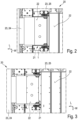
- a c-shaped gap 21 is present, as best to be seen in fig. 3 .
- the c-shaped gap 21 in between the modules 23 is at least partially closed by the adjustable adapter 1.
- the c-shaped gap 21 is closed by the adjustable adapter 1 so that sample containers can be prevented from falling through the c-shaped gap 21.
- the adjustable adapter 1 is used in the laboratory system 20 to cover or close the c-shaped gap 21 in between the modules 23.
- the adjustable adapter 1 has a base 2.
- the base 2 extends along a width direction W of the adjustable adapter 1.
- the adjustable adapter 1 has a pair of legs 3. Each leg 3 protrudes from the base 2 in a length direction L of the adjustable adapter 1 so that the base 2 and the legs 3 are arranged in a c-shape of the adjustable adapter 1.
- the base 2 is adjustable to set its dimension D along the length direction L.
- the base 2 of the adjustable adapter 1 is adjusted so that the dimension D of the base 2 along the length direction L is set in correspondence to a base portion of to the c-shaped gap 21.
- the base 2 of the adjustable adapter 1 is adjusted so that tolerances of a distance in between both the modules 23 is compensated.
- the base 2 has two end portions 4 which are arranged opposite one another along the width direction W. Therein, each leg 3 protrudes from the base 2 at a respective end portion 4.
- the legs 3 may be substantially in parallel.
- the legs 3 may be mirror symmetric.
- the length direction L may be perpendicular to the width direction W.
- the width direction W and the length direction L may span a horizontal plane.
- the horizontal plane can be perpendicular to gravity.
- the horizontal plane may contain or be parallel to the c-shaped gap 21 and/or the inner surfaces 22 and/or the c-shape of the adjustable adapter 1.
- the inner surfaces 22 of the modules 23 can be connected with one another at least substantially flush or evenly by the adjustable adapter 1.
- the base 2 comprises a first unit 5 and a second unit 4, as best to be seen in figs. 5 to 7 .
- the first unit 5 overlaps the second unit 6 with respect to the length direction L.
- the first unit 5 has both the end portions 4.
- the legs 3 are fixed to the first unit 5 at a respective end portion 4.
- a position of the second unit 6 is adjustable relative to the first unit 5 along the length direction L.
- the dimension D of the base 2 can be set with respect to the length direction L.
- the base 2 is adjusted so that the base 2 has its maximal dimension D2 along the length direction L.
- the base 2 is adjusted so that it has its minimal dimension D1 along the length direction L.
- the second unit 6 is guided at the legs 3 along the length direction L.
- the second unit 6 can be guided at the first unit 5 along the length direction L.
- the second unit 6 is guided in a drawer-like manner.
- the adjustable adapter 1 has at least one linear guide 7 for guiding the second unit 6 relative to the first unit 5 along the length direction L.
- the linear guide 7 can comprise a slot extending along the length direction L and a sliding element movably accepted or received in the slot.
- the second unit 6 is guided in between a first end position P1 of the second unit 6 and a second end position P2 of the second unit 6 relative to the first unit 5. In fig. 5 , the second unit 6 is in its second end position P2.
- the second unit 6 is in its first end position P1.
- the base 2 can have its min. dimension D1 along the length direction L.
- the base 2 can have its max. dimension D2 along the length direction L.
- the first unit 5 comprises a lamella 13.
- the lamella 13 is arranged in between a body 14 of the first unit 5 and the second unit 6.
- the lamella 13 is arranged in between the body 14 and the second unit 6 with respect to gravity.
- the lamella 13 is guided at the body 14 and/or at the second unit 6 along the length direction L.
- the lamella 13 may allow for enlarging a distance in between the first end position P1 and the second end position P2 of the second unit 6.
- the adjustable adapter 1 has at least one fastener 8.
- the fastener 8 is adapted for releasable fixation of a present adjustment or setting of the base 2.
- the fastener 8 can comprise a clamping screw 9.
- the base 2 has a through-slot 10 extending along a width direction W.
- the legs 3 - in the example of the figs. each of the legs 3 - has a through-slot 10 extending along the width direction W.
- the through-slot 10 is adapted to receive or accept a fastening element 11.
- the fastening element 11 can be a threaded bolt 12.
- the fastening element 11, for example, is adapted for fastening the adjustable adapter 1 to at least one of the modules 23.
- the through-slot 10 allows for compensation of tolerances regarding the positioning of the modules 23 relative to one another with respect to the width direction W.
- the through-slots 10 can allow for compensation of a lateral offset or misalignment of the two modules 23 relative to one another.
- the adjustable adapter 1 may allow for compensation of at least minor angular misalignment of the modules 23.
- the second unit 6 may be made from sheet metal.
- the first unit 5 may be made from sheet metal.
- the body 14 may be made from sheet metal.
- the lamella 13 may be made from sheet metal.
- the lamella 13 may be substantially flat.
- the second unit 6 may have an S-shaped cross-section, the cross section being oriented perpendicular to the width direction W.
- the lamella 13 can have a protrusion. At least at the protrusion, an extension of the lamella 13 along the length direction L can be greater than an extension of the body 14 and/or of the second unit 6 along the length direction L.
- An initial installation of the laboratory system 20 can be carried out as follows.
- the transport module 24 can be positioned on a laboratory floor and aligned so that its transport surface extends horizontally.
- the sorter module 25 can be positioned relative to the transport module 24 by moving the sorter module 25 towards the transport module 24.
- the sorter module 25 may have wheels rolling on the laboratory floor.
- the sorter module 25 may be moved towards the transport module 24 until a tongue-shaped protrusion of the transport module 24 reaches into an interior of the sorter module 25.
- the position of the sorter module 25 relative to the transport module 24 can be fixated or figuratively frozen.
- non-slip feet of the sorter module 25 can be extended downwards, in particular by a screw or lever mechanism or alike, until the feet get in contact with the laboratory floor.
- the sorter module 25 can be jacked up by extending the feet. Alternatively, wheels of the sorter module 25 can be retracted. By extending the feet individually, the sorter module 25 then can be aligned horizontally. Due to unevenness of the laboratory floor, the c-shaped gap 21 in between the transport module 24 and the sorter module 25 can be due to tolerances with respect to both the width direction W and the length direction L.
- the adjustable adapter 1 can be adapted to compensate for those tolerances.
- the adjustable adapter 1 may allow for compensation of at least minor angular misalignment of the modules 23.
- the adjustable adapter 1 can allow for closing the c-shaped gap 21 along the length direction L as well as along the width direction W, in particular so that sample containers can be prevented from falling through the c-shaped gap 21 in case of a malfunction of the transport system 20.
- tolerances of the c-shaped gap 21 can be compensated by the legs 3 using the through-slots 10.
- a distance in between the legs 3 along the width direction L can be constant or non-adjustable.
- the distance in between the legs 3 can correspond to a width of the transport module 24, in particular of the tongue-shaped protrusion of the transport module 24 reaching into the interior of the sorter module 25.
- the second unit 6 can be moved towards the transport module 24. Then, the second unit 6 can be fastened to the legs 3 by the fasteners 8. Then, the lamella 13 may be moved away from the transport module 24 until the c-shaped gap 21, in particular the base portion of the c-shaped gap 21, in between the sorter module 25 and the transport module 24 is closed. Therein, the lamella 13 may cover a portion of the gap 21.
- the body 14 can be rigidly connected to the legs 3.
- a frame of the sorter module 25 can have a gap or slot which ensures that the adjustable adapter 1, in particular the lamella 13 and/or the second unit 6, stays in horizontal orientation. The gap of the frame may be adapted to guide the protrusion of the lamella 13.
Landscapes
- Health & Medical Sciences (AREA)
- Chemical & Material Sciences (AREA)
- Clinical Laboratory Science (AREA)
- Chemical Kinetics & Catalysis (AREA)
- General Health & Medical Sciences (AREA)
- Biochemistry (AREA)
- Physics & Mathematics (AREA)
- General Physics & Mathematics (AREA)
- Immunology (AREA)
- Pathology (AREA)
- Analytical Chemistry (AREA)
- Life Sciences & Earth Sciences (AREA)
- Automatic Analysis And Handling Materials Therefor (AREA)
Abstract
Description
- The invention relates to an adjustable adapter for closing a c-shaped gap in between two modules of a laboratory system. Furthermore, the invention relates to such a laboratory system.
- Typically, avoiding a gap in between two modules of a common laboratory system requires particular precise and exhaustive positioning of both the modules relative to one another.
- It is an object of the present invention to provide for an adjustable adapter for closing a c-shaped gap in between two modules of a laboratory system, and to provide for such a laboratory system, enabling simplification of positioning of the two modules relative to one another.
- This object is solved by the subject-matter of the independent claims, respectively. Preferred embodiments are subject-matter of the dependent claims.
- The adjustable adapter according to the invention is adapted for closing a c-shaped gap in between two modules of a laboratory system. The laboratory system may be a laboratory sample distribution system. The adjustable adapter comprises a base. The base extends along a width direction of the adjustable adapter. The adjustable adapter has a pair of legs. Each of the legs protrudes from the base in a length direction of the adjustable adapter so that the base and the legs are arranged in a c-shape of the adjustable adapter. The base and the legs together can form the c-shape of the adjustable adapter. Therein, the base is adjustable to set its dimension along the length direction. Thus, inaccuracies in the positioning of the two modules relative to one another can be at least partially compensated regarding the length direction by accordingly adjusting the base. This can ensure that the c-shaped gap is closed even if the relative positioning of the two modules along the length direction has particularly high tolerances. Since the adjustable adapter enables to reliably close the c-shaped gap even at particularly high positioning tolerances, positioning of the modules relative to one another can be simplified.
- In particular, the c-shaped gap in between the two modules is to be closed as to avoid objects processed and/or transported by the laboratory system from falling into and/or through the c-shaped gap. Such an object may be a laboratory sample container. The c-shaped gap can extend in a horizontal plane containing respective inner surfaces of both the modules, said inner surfaces to be connected at least substantially flush or evenly by the adjustable adapter. The width direction may be perpendicular to the length direction. The width direction and the length direction may span the horizontal plane. The width direction and the length direction may be perpendicular to gravity.
- According to an embodiment of the invention, the base has two end portions. The end portions are located or arranged opposite one another along the width direction. Therein, each of the legs protrudes from the base at a respective end portion. Thus, the base and both the legs can partially enclose a tongue-shaped portion of one of the modules. The tongue-shaped portion may protrude into an interior of the other module of the laboratory system along the length direction. The other module may have a recess for accepting or receiving the tongue-shaped protrusion with a clearance, the clearance providing for the c-shaped gap.
- According to another embodiment of the invention, the base has a first unit and a second unit. Therein, the first unit overlaps the second unit with respect to the length direction. With respect to gravity, the first unit may be located of arranged above the second unit. The first unit comprises both the end portions of the base. Therein, the legs are each fixed at or to a respective end portion. A position of the second unit is adjustable relative to the first unit along the length direction in order to set the dimension of the base along the length direction. The first unit and the second unit can form a telescopic mechanism of the base.
- According to another embodiment of the invention, the second unit is guided at the legs along the length direction. Alternatively, or additionally, the second unit is guided at the first unit along the length direction. In particular, the second unit is guided in a drawer-like manner. This allows for particularly easy adjustment of the base.
- According to another embodiment of the invention, the adjustable adapter has at least one linear guide for guiding the second unit relative to the first unit along the length direction. Additionally, or alternatively, the second unit is guided in between a first end position of the second unit and a second end position of the second unit, in both cases relative to the first unit. In particular, the second unit is guided steplessly in between both its end positions. A distance between the end positions may correspond to the tolerances to be compensated by adjusting the adjustable adapter.
- According to another embodiment of the invention, the first unit has a lamella arranged in between a body of the first unit and the second unit. Therein, the lamella is guided at the body along the length direction. Additionally, or alternatively, the lamella is guided at the second unit along the length direction. The lamella allows for a particularly great variation in the distance between the end positions of the second unit, thus enabling compensation of particular high positioning tolerances. The lamella may form an intermediate segment of the telescopic mechanism of the adjustable adapter.
- According to another embodiment of the invention, the adjustable adapter has at least one fastener. The fastener is adapted for releasable fixation of a present adjustment or setting of the base. In particular, the fastener comprises a clamping screw. The fastener can be a quick-fastener.
- According to another embodiment of the invention, the base has at least one through-slot extending along the width direction. Alternatively, or additionally, at least one of the legs, in particular each of the legs, has at least one through-slot extending along the width direction. At least one of the legs, in particular each of the legs, can have an overhang outwardly projecting along the width direction, in particular horizontally, said overhang comprising the through-slot. By such a through-slot, compensation of positioning tolerances along the width direction can be enabled, said positioning tolerances along the width direction being due to a tolerated lateral misalignment.
- As implicated above, the laboratory system according to the invention comprises two modules. Furthermore, the laboratory system has an adjustable adapter according to the invention as described above. Thus, the afore-described advantages of the adjustable adapter according to the invention transfer to the laboratory system according to the invention. In between the modules of the laboratory system, a c-shaped gap is present. The c-shaped gap is closed by the adjustable adapter, in particular at least partially. Therein, the base of the adjustable adapter is adjusted so that the dimension of the base along the length direction is set in correspondence to the c-shaped gap. In particular, the base of the adjustable adapter is adjusted so that it completely fills or covers a corresponding portion of the c-shaped gap along the length direction. The adjustable adapter of the laboratory system can allow for preventing objects from falling into or through the c-shaped gap. Such an object may be a sample container to be handled and/or transported by the laboratory system. In particular, the laboratory system is a laboratory sample distribution system. The two modules of the laboratory system can have a respective inner surface. Therein, the inner surfaces of the modules can be connected with one another by the adjustable adapter, in particular substantially evenly or flush. In particular, the inner surfaces can be of substantially horizontal orientation.
- According to an embodiment of the invention, a first of the modules of the laboratory system is a transport module of the laboratory system. The inner surface of the transport module can be a transport surface on which sample container carriers of the laboratory system can be driven, in particular by electromagnetic interaction. The sample container carriers can be adapted for carrying sample containers. A second of the modules of the laboratory system is a sorter module of the laboratory system. The sorter module can have a handling device, for example comprising a controllable gripper for gripping sample containers. The transport module is adapted for delivering sample containers to the sorter module. The handling device may be configured to part sample containers from sample container carriers provided by the transport module and to pass the sample containers on. The sorter module is adapted to sort delivered samples. In particular, the sorter module is adapted to sort delivered sample containers by selectively passing delivered sample containers on to further modules of the laboratory system.
- In particular, the adjustable adapter according to the invention is used in the laboratory sample system to cover the c-shaped gap in between the modules of the laboratory system.
- Further advantages and features of the invention arise from the claims as well as from the following description of a preferred embodiment of the invention, which is depicted by the drawings. Therein, equal reference signs relate to equal or similar or functionally equal components.
- It is to be understood that the features mentioned above as well as the features described below are not only usable in the stated combination, respectively, but also in other combinations or solely, without leaving the frame of the present invention.
- Fig. 1
- schematically depicts, in a perspective view, an embodiment of a laboratory system according to the invention, the laboratory system having an embodiment of an adjustable adapter according to the invention,
- fig. 2
- illustrates, in a top view, a detail of the laboratory system according to
fig. 1 , - fig. 3
- illustrates, in a top view, a detail of the laboratory system according to
figs. 1 and2 , wherein the adjustable adapter is blanked out, - fig. 4
- illustrates, in a perspective view, a detail of the laboratory system according to
figs. 1 to 3 , - fig. 5
- separately illustrates, in a perspective view, the adjustable adapter of the laboratory system according to
figs. 1 to 4 , wherein a base of the adjustable adapter is adjusted so that the base is set to its max. dimension along the length direction, - fig. 6
- depicts the adjustable adapter of
fig. 5 in a similar view, wherein the base is adjusted so that it is set to its min. dimension along the length direction, and - fig. 7
- illustrates, in another perspective view, the adjustable adapter according to
figs. 5 and6 . - A
laboratory system 20 has two modules 23. Both the modules 23 can be arranged in line. The modules 23 can be adapted for distribution of laboratory sample containers. Thus, thelaboratory system 20 can be a laboratory sample distribution system. Laboratory sample containers may be embodied as laboratory sample tubes having a circular cross-section. The laboratory sample containers can store a respective sample. The sample may be a liquid sample, e. g. a blood sample. - In the example of
figs. 1 to 4 , a first of the modules 23 is a transport module 24 of thelaboratory system 20. For example, the transport module 24 has aninner surface 22 which comprises a transport surface. The transport surface of the transport module 24 can comprise an electromagnetic device for electro-magnetically driving sample container carriers of thelaboratory system 20 on top of the transport surface. Such sample container carriers can be adapted for carrying laboratory sample containers. A second of the modules 23 is a sorter module 25 of thelaboratory system 20. The sorter module 25 can have aninner surface 22. The transport module 24 is adapted for delivering sample containers to the sorter module 25. The sorter module 25 is adapted to sort delivered sample containers. For example, the sorter module 25 can sort delivered sample containers by selectively passing the sample containers on to further modules of thelaboratory system 20. The further modules may be adapted to process and/or analyze a respective sample stored in a passed-on sample container. - The
laboratory system 20 comprises anadjustable adapter 1 as separately depicted infigs. 5 to 7 . Therein, in between the modules 23 a c-shapedgap 21 is present, as best to be seen infig. 3 . The c-shapedgap 21 in between the modules 23 is at least partially closed by theadjustable adapter 1. For example, the c-shapedgap 21 is closed by theadjustable adapter 1 so that sample containers can be prevented from falling through the c-shapedgap 21. According to the figs., theadjustable adapter 1 is used in thelaboratory system 20 to cover or close the c-shapedgap 21 in between the modules 23. - The
adjustable adapter 1 has abase 2. Thebase 2 extends along a width direction W of theadjustable adapter 1. Theadjustable adapter 1 has a pair oflegs 3. Eachleg 3 protrudes from thebase 2 in a length direction L of theadjustable adapter 1 so that thebase 2 and thelegs 3 are arranged in a c-shape of theadjustable adapter 1. Thebase 2 is adjustable to set its dimension D along the length direction L. In thelaboratory system 20 according tofigs. 1 to 4 , thebase 2 of theadjustable adapter 1 is adjusted so that the dimension D of thebase 2 along the length direction L is set in correspondence to a base portion of to the c-shapedgap 21. Thus, thebase 2 of theadjustable adapter 1 is adjusted so that tolerances of a distance in between both the modules 23 is compensated. - For example, the
base 2 has twoend portions 4 which are arranged opposite one another along the width direction W. Therein, eachleg 3 protrudes from thebase 2 at arespective end portion 4. Thelegs 3 may be substantially in parallel. Thelegs 3 may be mirror symmetric. The length direction L may be perpendicular to the width direction W. The width direction W and the length direction L may span a horizontal plane. The horizontal plane can be perpendicular to gravity. The horizontal plane may contain or be parallel to the c-shapedgap 21 and/or theinner surfaces 22 and/or the c-shape of theadjustable adapter 1. Theinner surfaces 22 of the modules 23 can be connected with one another at least substantially flush or evenly by theadjustable adapter 1. - For example, the
base 2 comprises afirst unit 5 and asecond unit 4, as best to be seen infigs. 5 to 7 . Therein, thefirst unit 5 overlaps thesecond unit 6 with respect to the length direction L. Thefirst unit 5 has both theend portions 4. Therein, thelegs 3 are fixed to thefirst unit 5 at arespective end portion 4. A position of thesecond unit 6 is adjustable relative to thefirst unit 5 along the length direction L. By adjusting the position of thesecond unit 6 relative to thefirst unit 5, the dimension D of thebase 2 can be set with respect to the length direction L. Infig. 5 thebase 2 is adjusted so that thebase 2 has its maximal dimension D2 along the length direction L. Contrarily tofig. 5 , according tofig. 6 , thebase 2 is adjusted so that it has its minimal dimension D1 along the length direction L. - In the embodiment shown in the figures, the
second unit 6 is guided at thelegs 3 along the length direction L. Alternatively, or additionally, thesecond unit 6 can be guided at thefirst unit 5 along the length direction L. For example, thesecond unit 6 is guided in a drawer-like manner. For example, theadjustable adapter 1 has at least onelinear guide 7 for guiding thesecond unit 6 relative to thefirst unit 5 along the length direction L. Thelinear guide 7 can comprise a slot extending along the length direction L and a sliding element movably accepted or received in the slot. For example, thesecond unit 6 is guided in between a first end position P1 of thesecond unit 6 and a second end position P2 of thesecond unit 6 relative to thefirst unit 5. Infig. 5 , thesecond unit 6 is in its second end position P2. On the contrary, infig. 6 , thesecond unit 6 is in its first end position P1. When thesecond unit 6 is in its first end position P1, thebase 2 can have its min. dimension D1 along the length direction L. When thesecond unit 6 is in its second end position P2, thebase 2 can have its max. dimension D2 along the length direction L. - According to the embodiment shown in the figures, the
first unit 5 comprises alamella 13. Thelamella 13 is arranged in between abody 14 of thefirst unit 5 and thesecond unit 6. For example, thelamella 13 is arranged in between thebody 14 and thesecond unit 6 with respect to gravity. Thelamella 13 is guided at thebody 14 and/or at thesecond unit 6 along the length direction L. Thelamella 13 may allow for enlarging a distance in between the first end position P1 and the second end position P2 of thesecond unit 6. - For example, the
adjustable adapter 1 has at least one fastener 8. The fastener 8 is adapted for releasable fixation of a present adjustment or setting of thebase 2. As to be seen from the figures, the fastener 8 can comprise a clamping screw 9. - For example, the
base 2 has a through-slot 10 extending along a width direction W. In addition, or as an alternative, at least one of the legs 3 - in the example of the figs. each of the legs 3 - has a through-slot 10 extending along the width direction W. Therein, the through-slot 10 is adapted to receive or accept a fastening element 11. The fastening element 11 can be a threaded bolt 12. The fastening element 11, for example, is adapted for fastening theadjustable adapter 1 to at least one of the modules 23. Therein, the through-slot 10 allows for compensation of tolerances regarding the positioning of the modules 23 relative to one another with respect to the width direction W. The through-slots 10 can allow for compensation of a lateral offset or misalignment of the two modules 23 relative to one another. Theadjustable adapter 1 may allow for compensation of at least minor angular misalignment of the modules 23. - The
second unit 6 may be made from sheet metal. Thefirst unit 5 may be made from sheet metal. Thebody 14 may be made from sheet metal. Thelamella 13 may be made from sheet metal. Thelamella 13 may be substantially flat. Thesecond unit 6 may have an S-shaped cross-section, the cross section being oriented perpendicular to the width direction W. Thelamella 13 can have a protrusion. At least at the protrusion, an extension of thelamella 13 along the length direction L can be greater than an extension of thebody 14 and/or of thesecond unit 6 along the length direction L. - An initial installation of the
laboratory system 20 can be carried out as follows. At first, the transport module 24 can be positioned on a laboratory floor and aligned so that its transport surface extends horizontally. Then, the sorter module 25 can be positioned relative to the transport module 24 by moving the sorter module 25 towards the transport module 24. The sorter module 25 may have wheels rolling on the laboratory floor. The sorter module 25 may be moved towards the transport module 24 until a tongue-shaped protrusion of the transport module 24 reaches into an interior of the sorter module 25. As soon as the sorter module 25 has a position relative to the transport module 24 within a predetermined tolerance, the position of the sorter module 25 relative to the transport module 24 can be fixated or figuratively frozen. - For fixation of the sorter module 25 relative to the transport module 24, non-slip feet of the sorter module 25 can be extended downwards, in particular by a screw or lever mechanism or alike, until the feet get in contact with the laboratory floor. The sorter module 25 can be jacked up by extending the feet. Alternatively, wheels of the sorter module 25 can be retracted. By extending the feet individually, the sorter module 25 then can be aligned horizontally. Due to unevenness of the laboratory floor, the c-shaped
gap 21 in between the transport module 24 and the sorter module 25 can be due to tolerances with respect to both the width direction W and the length direction L. Theadjustable adapter 1 can be adapted to compensate for those tolerances. Theadjustable adapter 1 may allow for compensation of at least minor angular misalignment of the modules 23. - The
adjustable adapter 1 can allow for closing the c-shapedgap 21 along the length direction L as well as along the width direction W, in particular so that sample containers can be prevented from falling through the c-shapedgap 21 in case of a malfunction of thetransport system 20. With respect to the width direction W, tolerances of the c-shapedgap 21 can be compensated by thelegs 3 using the through-slots 10. A distance in between thelegs 3 along the width direction L can be constant or non-adjustable. Thus, the distance in between thelegs 3 can correspond to a width of the transport module 24, in particular of the tongue-shaped protrusion of the transport module 24 reaching into the interior of the sorter module 25. - After the
legs 3 of theadjustable adapter 1 are fastened to the sorter module 25, thesecond unit 6 can be moved towards the transport module 24. Then, thesecond unit 6 can be fastened to thelegs 3 by the fasteners 8. Then, thelamella 13 may be moved away from the transport module 24 until the c-shapedgap 21, in particular the base portion of the c-shapedgap 21, in between the sorter module 25 and the transport module 24 is closed. Therein, thelamella 13 may cover a portion of thegap 21. Thebody 14 can be rigidly connected to thelegs 3. A frame of the sorter module 25 can have a gap or slot which ensures that theadjustable adapter 1, in particular thelamella 13 and/or thesecond unit 6, stays in horizontal orientation. The gap of the frame may be adapted to guide the protrusion of thelamella 13.
Claims (10)
- Adjustable adapter (1) for closing a c-shaped gap (21) in between two modules (23) of a laboratory system (20), the adjustable adapter (1) comprising- a base (2) extending along a width direction (W) of the adjustable adapter (1), and- a pair of legs (3) each protruding from the base (2) in a length direction (L) of the adjustable adapter (1) so that the base (2) and the legs (3) are arranged in a c-shape of the adjustable adapter (1),- the base (2) being adjustable to set its dimension (D, D1, D2) along the length direction (L).
- Adjustable adapter (1) according to claim 1, characterized in that- the base (2) has two end portions (4) arranged opposite one another along the width direction (W),- each leg (3) protruding from the base (2) at a respective end portion (4).
- Adjustable adapter (1) according to any of the preceding claims, characterized in that- the base (2) comprises a first unit (5) and a second unit (6), the first unit (5) overlapping the second unit (6) with respect to the length direction (L),- the first unit (5) having both the end portions (4) and the legs (3) being fixed thereat, respectively,- a position of the second unit (6) being adjustable relative to the first unit (5) along the length direction (L) as to set the dimension (D, D1, D2) of the base (2) along the length direction (L).
- Adjustable adapter (1) according to claim 3, characterized in that- the second unit (6) is guided at the legs (3) and/or at the first unit (5) along the length direction (L),- in particular the second unit (6) being guided in a drawer-like manner.
- Adjustable adapter (1) according to claim 3 or 4, characterized in that- the adjustable adapter (1) has at least one linear guide (7) for guiding the second unit (6) relative to the first unit (5) along the length direction (L), and/or- the second unit (6) being guided, in particular steplessly, in between a first end position (P1) of the second unit (6) and a second end position (P2) of the second unit (6) relative to the first unit (5).
- Adjustable adapter (1) according to any of claims 3 to 5, characterized in that- the first unit (5) has a lamella (13) arranged in between a body (14) of the first unit (5) and the second unit (6),- the lamella (13) being guided at the body (14) and/or at the second unit (6) along the length direction (L).
- Adjustable adapter (1) according to any of the preceding claims, characterized in that- the adjustable adapter (1) has at least one fastener (8) for releasable fixation of a present adjustment of the base (2),- in particular the fastener (8) comprising a clamping screw (9).
- Adjustable adapter (1) according to any of the preceding claims, characterized in that- the base (2) and/or at least one of the legs (3) has a through-slot (10) extending along the width direction (W),- the through-slot (10) being adapted to receive a fastening element (11), in particular a threaded bolt (12), for fastening the adjustable adapter (1) to at least one of the modules (23).
- Laboratory system (20) comprising- two modules (23), and- an adjustable adapter (1) according to any of the preceding claims,- wherein a c-shaped gap (21) in between the modules (23) is closed by the adjustable adapter (1),- wherein the base (2) of the adjustable adapter (1) is adjusted so that the dimension (D, D1, D2) of the base (2) along the length direction (L) is set in correspondence to the c-shaped gap (21).
- Laboratory system (20) according to claim 9, characterized in that- a first of the modules (23) is a transport module (24) of the laboratory system (20), and- a second of the modules (23) is a sorter module (25) of the laboratory system (20),- the transport module (24) being adapted for delivering sample containers to the sorter module (25),- the sorter module (25) being adapted to sort delivered sample containers, in particular by selectively passing delivered sample containers on to further modules of the laboratory system (20).
Priority Applications (4)
| Application Number | Priority Date | Filing Date | Title |
|---|---|---|---|
| EP23169881.2A EP4455677A1 (en) | 2023-04-25 | 2023-04-25 | Adjustable adapter and laboratory system |
| CN202410490348.7A CN118831665A (en) | 2023-04-25 | 2024-04-23 | Adjustable adapter and laboratory system |
| US18/642,895 US20240359186A1 (en) | 2023-04-25 | 2024-04-23 | Adjustable adapter and laboratory system |
| JP2024070364A JP2024157543A (en) | 2023-04-25 | 2024-04-24 | Adjustable adapter and laboratory system |
Applications Claiming Priority (1)
| Application Number | Priority Date | Filing Date | Title |
|---|---|---|---|
| EP23169881.2A EP4455677A1 (en) | 2023-04-25 | 2023-04-25 | Adjustable adapter and laboratory system |
Publications (1)
| Publication Number | Publication Date |
|---|---|
| EP4455677A1 true EP4455677A1 (en) | 2024-10-30 |
Family
ID=86226719
Family Applications (1)
| Application Number | Title | Priority Date | Filing Date |
|---|---|---|---|
| EP23169881.2A Pending EP4455677A1 (en) | 2023-04-25 | 2023-04-25 | Adjustable adapter and laboratory system |
Country Status (4)
| Country | Link |
|---|---|
| US (1) | US20240359186A1 (en) |
| EP (1) | EP4455677A1 (en) |
| JP (1) | JP2024157543A (en) |
| CN (1) | CN118831665A (en) |
Citations (4)
| Publication number | Priority date | Publication date | Assignee | Title |
|---|---|---|---|---|
| US5220748A (en) * | 1992-07-02 | 1993-06-22 | Wingate Chadbourne | Door and window casing assembly |
| CN101158534A (en) * | 2006-10-08 | 2008-04-09 | 海尔集团公司 | refrigerator sliding shelf |
| US20210373042A1 (en) * | 2020-05-29 | 2021-12-02 | Roche Diagnostics Operations, Inc. | Module for an automated laboratory system |
| CN114458007A (en) * | 2022-02-10 | 2022-05-10 | 中建二局第三建筑工程有限公司 | U-shaped rubber plugging device for root of wall formwork and mounting structure of U-shaped rubber plugging device |
-
2023
- 2023-04-25 EP EP23169881.2A patent/EP4455677A1/en active Pending
-
2024
- 2024-04-23 US US18/642,895 patent/US20240359186A1/en active Pending
- 2024-04-23 CN CN202410490348.7A patent/CN118831665A/en active Pending
- 2024-04-24 JP JP2024070364A patent/JP2024157543A/en active Pending
Patent Citations (4)
| Publication number | Priority date | Publication date | Assignee | Title |
|---|---|---|---|---|
| US5220748A (en) * | 1992-07-02 | 1993-06-22 | Wingate Chadbourne | Door and window casing assembly |
| CN101158534A (en) * | 2006-10-08 | 2008-04-09 | 海尔集团公司 | refrigerator sliding shelf |
| US20210373042A1 (en) * | 2020-05-29 | 2021-12-02 | Roche Diagnostics Operations, Inc. | Module for an automated laboratory system |
| CN114458007A (en) * | 2022-02-10 | 2022-05-10 | 中建二局第三建筑工程有限公司 | U-shaped rubber plugging device for root of wall formwork and mounting structure of U-shaped rubber plugging device |
Also Published As
| Publication number | Publication date |
|---|---|
| JP2024157543A (en) | 2024-11-07 |
| CN118831665A (en) | 2024-10-25 |
| US20240359186A1 (en) | 2024-10-31 |
Similar Documents
| Publication | Publication Date | Title |
|---|---|---|
| US6012568A (en) | Adjustable conveyor | |
| US10362871B2 (en) | Device and method for fixing a push element | |
| US6109426A (en) | Oriented bottle conveyor | |
| US20090272074A1 (en) | Transport system for handling multi-width flexible pouches | |
| JP7709453B2 (en) | Conveyor Guide Rail Attachment | |
| US20240359186A1 (en) | Adjustable adapter and laboratory system | |
| US3844405A (en) | Quick adjusting guide rail for conveyor | |
| AU2017296217A1 (en) | Adjustable idler support system for conveyor belt | |
| US10206503B2 (en) | Device and method for fixing a push element | |
| AU2017256412A1 (en) | Fastening device and method for fastening at least one sensor to a railway rail | |
| EP1311409A4 (en) | Flat goods clamping and transporting apparatus | |
| CN109483579A (en) | A kind of Intelligent assembly flexible grabbing device | |
| CN109108870B (en) | Stacked platform mechanism | |
| KR101772356B1 (en) | Adjusting mechanizm for track, conveying apparatus, and vibratory conveying apparatus | |
| SK278311B6 (en) | System for guiding of the slide | |
| US20190210819A1 (en) | Aligning Ramp for Aligning a Shipping Container Loaded on a Vehicle, and Combination of a Shipping Container Loaded on a Vehicle and the Aligning Ramp | |
| CN109399119B (en) | A welding tool suitable for belt conveyor trough roller beams with different bandwidths | |
| CN108942028B (en) | Automobile body side wall clamp | |
| EA011660B1 (en) | Lateral bracket of conveyor guide | |
| CN208245029U (en) | A conveying fixture assembly used in an automobile lamp housing spraying production line | |
| EP3154879B1 (en) | Transport system | |
| EP4682091A1 (en) | Induction board for a conveyor system | |
| US11477909B2 (en) | Attachment member, member attachment structure, and member attachment method | |
| US8322517B1 (en) | Lightweight conveyor pallet | |
| DE102024124431A1 (en) | Format part for supporting a container during transport |
Legal Events
| Date | Code | Title | Description |
|---|---|---|---|
| PUAI | Public reference made under article 153(3) epc to a published international application that has entered the european phase |
Free format text: ORIGINAL CODE: 0009012 |
|
| STAA | Information on the status of an ep patent application or granted ep patent |
Free format text: STATUS: THE APPLICATION HAS BEEN PUBLISHED |
|
| AK | Designated contracting states |
Kind code of ref document: A1 Designated state(s): AL AT BE BG CH CY CZ DE DK EE ES FI FR GB GR HR HU IE IS IT LI LT LU LV MC ME MK MT NL NO PL PT RO RS SE SI SK SM TR |
|
| STAA | Information on the status of an ep patent application or granted ep patent |
Free format text: STATUS: REQUEST FOR EXAMINATION WAS MADE |
|
| 17P | Request for examination filed |
Effective date: 20250425 |
|
| GRAP | Despatch of communication of intention to grant a patent |
Free format text: ORIGINAL CODE: EPIDOSNIGR1 |
|
| STAA | Information on the status of an ep patent application or granted ep patent |
Free format text: STATUS: GRANT OF PATENT IS INTENDED |
|
| INTG | Intention to grant announced |
Effective date: 20260319 |