EP4455632A1 - Trace gas sampling device and detection system - Google Patents
Trace gas sampling device and detection system Download PDFInfo
- Publication number
- EP4455632A1 EP4455632A1 EP22909178.0A EP22909178A EP4455632A1 EP 4455632 A1 EP4455632 A1 EP 4455632A1 EP 22909178 A EP22909178 A EP 22909178A EP 4455632 A1 EP4455632 A1 EP 4455632A1
- Authority
- EP
- European Patent Office
- Prior art keywords
- sampling
- vapor
- target
- air pump
- trace
- Prior art date
- Legal status (The legal status is an assumption and is not a legal conclusion. Google has not performed a legal analysis and makes no representation as to the accuracy of the status listed.)
- Granted
Links
Images

Classifications
-
- G—PHYSICS
- G01—MEASURING; TESTING
- G01N—INVESTIGATING OR ANALYSING MATERIALS BY DETERMINING THEIR CHEMICAL OR PHYSICAL PROPERTIES
- G01N1/00—Sampling; Preparing specimens for investigation
- G01N1/02—Devices for withdrawing samples
- G01N1/22—Devices for withdrawing samples in the gaseous state
- G01N1/2202—Devices for withdrawing samples in the gaseous state involving separation of sample components during sampling
- G01N1/2214—Devices for withdrawing samples in the gaseous state involving separation of sample components during sampling by sorption
-
- G—PHYSICS
- G01—MEASURING; TESTING
- G01N—INVESTIGATING OR ANALYSING MATERIALS BY DETERMINING THEIR CHEMICAL OR PHYSICAL PROPERTIES
- G01N1/00—Sampling; Preparing specimens for investigation
- G01N1/02—Devices for withdrawing samples
- G01N1/22—Devices for withdrawing samples in the gaseous state
- G01N1/26—Devices for withdrawing samples in the gaseous state with provision for intake from several spaces
-
- G—PHYSICS
- G01—MEASURING; TESTING
- G01N—INVESTIGATING OR ANALYSING MATERIALS BY DETERMINING THEIR CHEMICAL OR PHYSICAL PROPERTIES
- G01N1/00—Sampling; Preparing specimens for investigation
- G01N1/02—Devices for withdrawing samples
- G01N2001/022—Devices for withdrawing samples sampling for security purposes, e.g. contraband, warfare agents
Definitions
- At least an embodiment of the present disclosure relates to a security inspection system, and in particular, to a trace vapor sampling device for security inspection and a detection system including such sampling device.
- IMS Ion Mobility Spectrometry
- the IMS technology mainly includes three components: a drift tube for ion detection, a sample inlet (also known as a thermal desorber), and a swab for collecting trace samples.
- the IMS technology may also be used as a trace detection technology for industrial toxic gases and chemical warfare agents, and has been applied to security inspection in military and police systems.
- trace detection devices which use the IMS technology are mainly used as commonly used security inspection devices for cargo inspection.
- Such a device requires handholding a swab (wearing gloves) or a sampler to wipe and collect samples directly on surfaces of relevant personnel and cargoes, and then the collected swab is insert into the sample inlet to wait for analysis results.
- a swab wearing gloves
- a sampler to wipe and collect samples directly on surfaces of relevant personnel and cargoes, and then the collected swab is insert into the sample inlet to wait for analysis results.
- the entire sampling process of the device requires manual operation, which is very cumbersome.
- the commonly used trace detection devices are also difficult to directly inspect items inside packages of cargoes. When suspected contrabands are located inside the packages and are too far away from the operator or blocked by other items, it may be difficult for the operator to directly sample the suspected contrabands, and it may cause missed inspections when sampling surrounding surfaces.
- the main purpose of the present disclosure is to provide a trace vapor sampling device and a detection system, so as to at least partially solve at least one technical problem mentioned above and in other aspects.
- a trace vapor sampling device including: a moving carrier; a plurality of sampling apparatuses provided on the moving carrier, including: a sampling hose configured to go deep into an inside of a target to be inspected and acquire a target vapor inside the target; a sampling channel connected to the sampling hose and configured to transmit the target vapor; and a pre-concentrator provided in the sampling channel, an adsorption medium is placed inside the pre-concentrator, and the target vapor is adsorbed onto the adsorption medium; a control apparatus provided on the moving carrier; and at least one air pump, each air pump is controllably communicated with one or more sampling apparatuses, and the control apparatus controls each air pump to be selectively communicated with one sampling apparatus or one of the plurality of sampling apparatuses, so that the air pump drives the sampling hose of the communicated sampling apparatus to acquire the target vapor.
- the trace vapor sampling device includes: an air pump, the control apparatus controls the air pump to be selectively communicated with one of the plurality of sampling apparatuses.
- the trace vapor sampling device includes: a plurality of air pumps, the control apparatus controls each air pump to be communicated with a corresponding sampling apparatus.
- the pre-concentrator is provided with a first heating element, and the first heating element is configured to heat the adsorption medium, so as to separate the target vapor adsorbed on the adsorption medium from the adsorption medium.
- a flow rate of the air pump is greater than or equal to 1L/min.
- the sampling channel includes: a sample inlet provided with a fast interface, the sampling hose is connected to the fast interface of the sample inlet; and an exhaust port configured to discharge a residual vapor in the pre-concentrator.
- the sampling channel further including: an information recording apparatus configured to record target information of the target.
- the information recording apparatus includes a camera, a scanning gun and a wireless radio frequency identification reader-writer.
- control apparatus further includes: a communication unit connected to the camera, the scanning gun and the wireless radio frequency identification reader-writer respectively and configured to transmit the target information, the communication unit includes a communication interface configured to receive the target information.
- the moving carrier is a robot moving carrier.
- a detection system including: the trace vapor sampling device as described above; and an analysis device configured to inspect and analyze the target vapor acquired by the sampling apparatus or the adsorption medium adsorbed with the target vapor so as to obtain an analysis result.
- the analysis device includes: an analysis device sample inlet configured to acquire the target vapor; a detection apparatus configured to inspect the target vapor to obtain an inspection signal; a computing apparatus connected to the detection apparatus and configured to calculate and analyze the inspection signal so as to obtain the analysis result.
- a second heating element is provided on the analysis device sample inlet, and the second heating element is configured to heat the adsorption medium placed in the analysis device sample inlet so as to acquire the target vapor.
- the analysis device further includes: a semi-permeable membrane provided between the analysis device sample inlet and the detection apparatus and configured to selectively filter the target vapor.
- the detection apparatus includes at least one of an ion mobility spectrometer, a miniature mass spectrometer, a GC-IMS, a FAIMS, an electrochemical sensor array, a photoacoustic spectrum sensor, a QCL infrared spectrum system, an amplifying fluorescent polymer sensor and/or a quartz crystal microbalance detector.
- the trace vapor sampling device and the detection system provided by the present disclosure, through acquiring the target vapor using the sampling hose, adsorbing the target vapor onto the adsorption medium using the pre-concentrator, and acquiring the target vapor using at least one air pump to drive the sampling hose of the communicated sampling apparatus, it is possible to achieve the sampling of the target to be inspected.
- This sampling process does not require manual operation, which reduces labor consumption.
- a trace vapor sampling device including:
- a detection system including:
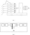
- FIG. 1 is a schematic diagram of a structure of a sampling device according to an embodiment of the present disclosure.
- the trace vapor sampling device includes: a moving carrier 1, a plurality of sampling apparatuses 2, a control apparatus 3 and at least one air pump 9.
- the plurality of sampling apparatuses 2 are provided on the moving carrier 1, the sampling apparatus includes a sampling hose 21, a sampling channel 22 and a pre-concentrator 23.
- the sampling hose 21 is configured to go deep into an inside of a target to be inspected (such as a container, a cargo box, a luggage box, etc.) to acquire a target vapor inside the target.
- the sampling hose 21 may go deep into the inside of the target to be inspected, for example, the sampling hose may go deep into a package of the cargo to be inspected.
- a length of the sampling hose 21 may be adjusted, so that the sampling hose 21 may go deep into the inside of the target to be inspected by a long distance. In addition, the sampling hose 21 may go deep into the inside of the target to be inspected by bypassing blocking of a physical structure.
- the sampling channel 22 is connected to the sampling hose 21, and the sampling channel is configured to transmit the target vapor.
- FIG. 2 is a schematic diagram of a partial structure of the sampling apparatus in FIG. 1 .
- the pre-concentrator 23 is provided in the sampling channel 22.
- An adsorption medium 24 is placed inside the pre-concentrator 23.
- the target vapor is adsorbed onto the adsorption medium 24.
- the control apparatus 3 is provided on the moving carrier 1.
- Each of the at least one air pump 9 is controllably communicated with one or more sampling apparatuses 2.
- the control apparatus 3 controls each air pump 9 to be selectively communicated with one sampling apparatus 2 or one of the plurality of sampling apparatuses 2, so that the air pump 9 drives the sampling hose 21 of the communicated sampling apparatus 2 to acquire the target vapor.
- the sampling device provided in the present disclosure acquires the target vapor using the sampling hose 21, the target vapor is adsorbed onto the adsorption medium 24 using the pre-concentrator 23, and the target vapor is acquired using the sampling hose 21 of the communicated sampling apparatus driven by the at least one vapor pump 9, thus the sampling of a target to be inspected is achieved.
- This sampling process does not require manual operation.
- the sampling device avoids using the swab for sampling and therefore the costs are low.
- the sampling channel 22 includes: a sample inlet 221 and an exhaust port 222.
- a fast interface is provided on the sample inlet, and the sampling hose 21 is connected to the fast interface of the injection port 221.
- the exhaust port 222 is configured to discharge residual vapor in the pre-concentrator 23.
- the sampling device includes an air pump 9.
- the control apparatus 3 controls the air pump 9 to be selectively communicated with one of the plurality of sampling apparatuses 2.
- the sampling apparatuses 2 may be alternately used by switching among the sampling apparatuses.
- the sampling device includes a plurality of air pumps 9.
- the control apparatus 3 controls each air pump 9 to be communicated with a corresponding sampling apparatus 2.
- the plurality of air pumps 9 and communicated each air pump 9 with a corresponding sampling apparatus 2 it is possible to achieve simultaneous sampling of a plurality of targets.
- the pre-concentrator 23 is provided with a first heating element (not shown in the drawing).
- the first heating element is configured to heat the adsorption medium 24 so as to separate the target vapor adsorbed onto the adsorption medium 24 from the adsorption medium 24.
- a flow rate of the air pump 9 is greater than or equal to 1L/min.
- the flow rate of the air pump 9 may be set according to volumes of cargoes.
- the above sampling device further includes an information recording apparatus 4 configured to record target information of the target.
- the information recording apparatus includes a camera 41, a scanning gun 42 and a wireless radio frequency identification reader-writer 43, and the information recording apparatus is used to record information of cargoes and items to be inspected.
- control apparatus 3 further includes a communication unit (not shown in the drawing) connected to the camera 41, the scanning gun 42 and the wireless radio frequency identification reader-writer 43, respectively, and is configured to transmit the target information.
- the communication unit includes a communication interface (not shown in the drawing) for receiving the target information.
- the moving carrier is a robot moving carrier.
- the moving carrier may be manually controlled or automatically controlled by the robot, so as to reach a vicinity of the cargo to be inspected.
- a detection system including the trace vapor sampling device as described above and an analysis device.
- the analysis device is configured to inspect and analyze the target vapor acquired by the sampling apparatus or the adsorption medium 24 adsorbed with the target vapor so as to obtain an analysis result.
- FIG. 3 is a schematic diagram of a structure of an analysis device according to an embodiment of the present disclosure.
- the detection device includes: an analysis device sample inlet 5, a detection apparatus 7 and a computing apparatus 8.
- the analysis device sample inlet 5 is configured to acquire the target vapor.
- the detection apparatus 7 is configured to inspect the target vapor to obtain an inspection signal.
- the computing apparatus 8 is connected to the detection apparatus 7 and configured to calculate and analyze the inspection signal so as to obtain the analysis result.
- a second heating element (not shown in the drawing) is provided on the analysis device sample inlet 5.
- the second heating element is configured to heat the adsorption medium 24 placed in the analysis device sample inlet 5 so as to acquire the target vapor.
- the sampling channel 22 when inspecting the target vapor, may also be disassembled from the sampling device, and the exhaust port 222 of the sampling channel 22 may be communicated with the detection device sample inlet 5.
- the first heating element provided inside the pre-concentrator 23 instantly heats the adsorption medium 24, the target vapor adsorbed onto the adsorption medium 24 is detached and enters the analysis device sample inlet 5, so that the analysis device sample inlet 5 may acquire the target vapor.
- the analysis device further includes a semi-permeable membrane 6.
- the semi-permeable membrane 6 is provided between the analysis device sample inlet 5 and the detection apparatus 8, and is configured to filter the target vapor.
- the detection apparatus includes at least one of an ion mobility spectrometer, a miniature mass spectrometer, a GC-IMS, a FAIMS, an electrochemical sensor array, a photoacoustic spectrum sensor, a QCL infrared spectrum system, an amplifying fluorescent polymer sensor, and/or a quartz crystal microbalance detector.
- the target vapor collected in the present disclosure may be cross-validated from different perspectives using a plurality of inspection techniques, which is more accurate.
- the trace vapor sampling device and the detection system overcomes disadvantages that the relevant inhalation vapor sampling inspection system may not inspect samples with too low saturated vapor pressure.
- the trace vapor sampling device and the detection system of the embodiments of the present disclosure may achieve the sampling and inspection of contrabands such as explosives, drugs, etc. that are not easily volatile at room temperature and atmospheric pressure and have too low saturated vapor pressure.
- a sensitivity of relevant inhalation vapor sampling inspection system is usually at ppb-ppm level.
- the trace vapor sampling device and the inspection system in the embodiments of the present disclosure may have a higher inspection sensitivity, which may reach a level of ppb to ppt.
- the trace vapor sampling device and the detection system according to the embodiments of the present disclosure overcomes disadvantages of the related inhalation analysis device that is difficult to conduct a one-time inspection of large air cargo boxes, truck carriages, and container loads containing a large number of items without opening packages of cargoes.
- the trace vapor sampling device and the detection system of the embodiments of the present disclosure have a plurality of sampling apparatuses, which may achieve simultaneous inspection of a plurality of cargoes.
- the trace vapor sampling device and the detection system overcomes disadvantages that the relevant analysis device may not quickly sample an entire box of cargoes in a short period of time.
- the air pump with a high flow rate, it is possible to achieve rapid inspection of cargoes with large volumes.
- the trace vapor sampling device and the detection system according to the embodiments of the present disclosure may be applied in fields of civil aviation, customs, logistics and other applications.
Landscapes
- Health & Medical Sciences (AREA)
- Life Sciences & Earth Sciences (AREA)
- Engineering & Computer Science (AREA)
- Biomedical Technology (AREA)
- Molecular Biology (AREA)
- Physics & Mathematics (AREA)
- Chemical & Material Sciences (AREA)
- Analytical Chemistry (AREA)
- Biochemistry (AREA)
- General Health & Medical Sciences (AREA)
- General Physics & Mathematics (AREA)
- Immunology (AREA)
- Pathology (AREA)
- Sampling And Sample Adjustment (AREA)
Abstract
Description
- This application claims priority to
Chinese Patent Application No. 202111597148.4, filed on December 24, 2021 - At least an embodiment of the present disclosure relates to a security inspection system, and in particular, to a trace vapor sampling device for security inspection and a detection system including such sampling device.
- Ion Mobility Spectrometry (IMS) technology, as a trace inspection technology for rapidly inspecting explosives and drugs, has been widely used in security inspection in fields such as airports, customs, subways and government agencies. The IMS technology mainly includes three components: a drift tube for ion detection, a sample inlet (also known as a thermal desorber), and a swab for collecting trace samples. The IMS technology may also be used as a trace detection technology for industrial toxic gases and chemical warfare agents, and has been applied to security inspection in military and police systems.
- At present, trace detection devices which use the IMS technology are mainly used as commonly used security inspection devices for cargo inspection. Such a device requires handholding a swab (wearing gloves) or a sampler to wipe and collect samples directly on surfaces of relevant personnel and cargoes, and then the collected swab is insert into the sample inlet to wait for analysis results. However, the entire sampling process of the device requires manual operation, which is very cumbersome.
- During the cargo inspection, since various parts of the surface of an item to be inspected require to be sampled, and the swab belongs to consumables, a consumption of consumables may be increased accordingly when the number of inspection increases, and the application costs may be higher.
- The commonly used trace detection devices are also difficult to directly inspect items inside packages of cargoes. When suspected contrabands are located inside the packages and are too far away from the operator or blocked by other items, it may be difficult for the operator to directly sample the suspected contrabands, and it may cause missed inspections when sampling surrounding surfaces.
- In view of this, the main purpose of the present disclosure is to provide a trace vapor sampling device and a detection system, so as to at least partially solve at least one technical problem mentioned above and in other aspects.
- According to the embodiments of the present disclosure, a trace vapor sampling device is provided, including: a moving carrier; a plurality of sampling apparatuses provided on the moving carrier, including: a sampling hose configured to go deep into an inside of a target to be inspected and acquire a target vapor inside the target; a sampling channel connected to the sampling hose and configured to transmit the target vapor; and a pre-concentrator provided in the sampling channel, an adsorption medium is placed inside the pre-concentrator, and the target vapor is adsorbed onto the adsorption medium; a control apparatus provided on the moving carrier; and at least one air pump, each air pump is controllably communicated with one or more sampling apparatuses, and the control apparatus controls each air pump to be selectively communicated with one sampling apparatus or one of the plurality of sampling apparatuses, so that the air pump drives the sampling hose of the communicated sampling apparatus to acquire the target vapor.
- According to the embodiments of the present disclosure, the trace vapor sampling device includes: an air pump, the control apparatus controls the air pump to be selectively communicated with one of the plurality of sampling apparatuses.
- According to the embodiments of the present disclosure, the trace vapor sampling device includes: a plurality of air pumps, the control apparatus controls each air pump to be communicated with a corresponding sampling apparatus.
- According to the embodiments of the present disclosure, the pre-concentrator is provided with a first heating element, and the first heating element is configured to heat the adsorption medium, so as to separate the target vapor adsorbed on the adsorption medium from the adsorption medium.
- According to the embodiments of the present disclosure, a flow rate of the air pump is greater than or equal to 1L/min.
- According to the embodiments of the present disclosure, the sampling channel includes: a sample inlet provided with a fast interface, the sampling hose is connected to the fast interface of the sample inlet; and an exhaust port configured to discharge a residual vapor in the pre-concentrator.
- According to the embodiments of the present disclosure, the sampling channel further including: an information recording apparatus configured to record target information of the target.
- According to the embodiments of the present disclosure, the information recording apparatus includes a camera, a scanning gun and a wireless radio frequency identification reader-writer.
- According to the embodiments of the present disclosure, the control apparatus further includes: a communication unit connected to the camera, the scanning gun and the wireless radio frequency identification reader-writer respectively and configured to transmit the target information, the communication unit includes a communication interface configured to receive the target information.
- According to the embodiments of the present disclosure, the moving carrier is a robot moving carrier.
- According to the embodiments of the present disclosure, a detection system is provided, including: the trace vapor sampling device as described above; and an analysis device configured to inspect and analyze the target vapor acquired by the sampling apparatus or the adsorption medium adsorbed with the target vapor so as to obtain an analysis result.
- According to the embodiments of the present disclosure, the analysis device includes: an analysis device sample inlet configured to acquire the target vapor; a detection apparatus configured to inspect the target vapor to obtain an inspection signal; a computing apparatus connected to the detection apparatus and configured to calculate and analyze the inspection signal so as to obtain the analysis result.
- According to the embodiments of the present disclosure, a second heating element is provided on the analysis device sample inlet, and the second heating element is configured to heat the adsorption medium placed in the analysis device sample inlet so as to acquire the target vapor.
- According to the embodiments of the present disclosure, the analysis device further includes: a semi-permeable membrane provided between the analysis device sample inlet and the detection apparatus and configured to selectively filter the target vapor.
- According to the embodiments of the present disclosure, the detection apparatus includes at least one of an ion mobility spectrometer, a miniature mass spectrometer, a GC-IMS, a FAIMS, an electrochemical sensor array, a photoacoustic spectrum sensor, a QCL infrared spectrum system, an amplifying fluorescent polymer sensor and/or a quartz crystal microbalance detector.
- According to the embodiments of the present disclosure, the trace vapor sampling device and the detection system provided by the present disclosure, through acquiring the target vapor using the sampling hose, adsorbing the target vapor onto the adsorption medium using the pre-concentrator, and acquiring the target vapor using at least one air pump to drive the sampling hose of the communicated sampling apparatus, it is possible to achieve the sampling of the target to be inspected. This sampling process does not require manual operation, which reduces labor consumption.
-
-
FIG. 1 is a schematic diagram of a structure of a sampling device according to an embodiment of the present disclosure; -
FIG. 2 is a schematic diagram of a partial structure of the sampling device inFIG. 1 ; -
FIG. 3 is a block diagram of a structure of an analysis device according to an embodiment of the present disclosure. -
- 1. moving carrier
- 2. sampling apparatus
- 21 sampling hose
- 22 sampling channel
- 221 sample inlet
- 222 exhaust port
- 23 pre-concentrator
- 24 adsorption medium
- 3. control apparatus
- 4. information recording apparatus
- 41 camera
- 42 scanning gun
- 43 wireless radio frequency identification reader-writer
- 5. analysis device sample inlet
- 6. semi-permeable membrane
- 7. detection apparatus
- 8. computing apparatus
- 9. air pump
- In order to make purposes, technical solutions and advantages of the present disclosure clearer, the present disclosure will be further explained in detail below, combined with specific embodiments and with reference to the accompanying drawings.
- However, it should be understood that these descriptions are only illustrative and not intended to limit the scope of the present disclosure. In addition, the descriptions of well-known structures and technologies are omitted in the following explanation to avoid unnecessary confusion with the concept of the present disclosure. Various structural diagrams according to the embodiments of the present disclosure are shown in the accompanying drawings. These drawings are not drawn to scale, and for the purpose of clear expression, certain details may be enlarged and certain details may be omitted.
- According to the entire inventive concept of an aspect of the present disclosure, a trace vapor sampling device is provided, including:
- a moving carrier;
- a plurality of sampling apparatuses provided on the moving carrier, including:
- a sampling hose configured to go deep into an inside of a target to be inspected and acquire a target vapor inside the target;
- a sampling channel connected to the sampling hose and configured to transmit the target vapor; and
- a pre-concentrator provided in the sampling channel, an adsorption medium is placed inside the pre-concentrator, and the target vapor is adsorbed onto the adsorption medium;
- a control apparatus provided on the moving carrier; and
- at least one air pump, each air pump is controllably communicated with one or more sampling apparatuses, and the control apparatus controls each air pump to be selectively communicated with one sampling apparatus or one of the plurality of sampling apparatuses, so that the air pump drives the sampling hose of the communicated sampling apparatus to acquire the target vapor.
- According to an entire concept of another aspect of the present disclosure, a detection system is provided, including:
- the above-mentioned trace vapor sampling device; and
- an analysis device configured to inspect and analyze the target vapor acquired by the sampling device or the adsorption medium adsorbed with the target vapor to obtain an analysis result.
-
FIG. 1 is a schematic diagram of a structure of a sampling device according to an embodiment of the present disclosure. - According to an exemplary embodiment of the present disclosure, as shown in
FIG. 1 , the trace vapor sampling device includes: a movingcarrier 1, a plurality ofsampling apparatuses 2, acontrol apparatus 3 and at least oneair pump 9. The plurality ofsampling apparatuses 2 are provided on the movingcarrier 1, the sampling apparatus includes asampling hose 21, asampling channel 22 and a pre-concentrator 23. Thesampling hose 21 is configured to go deep into an inside of a target to be inspected (such as a container, a cargo box, a luggage box, etc.) to acquire a target vapor inside the target. Thesampling hose 21 may go deep into the inside of the target to be inspected, for example, the sampling hose may go deep into a package of the cargo to be inspected. In addition, a length of thesampling hose 21 may be adjusted, so that thesampling hose 21 may go deep into the inside of the target to be inspected by a long distance. In addition, thesampling hose 21 may go deep into the inside of the target to be inspected by bypassing blocking of a physical structure. Thesampling channel 22 is connected to thesampling hose 21, and the sampling channel is configured to transmit the target vapor. -
FIG. 2 is a schematic diagram of a partial structure of the sampling apparatus inFIG. 1 . - In an embodiment, referring to
FIG. 1 and FIG. 2 in combination, the pre-concentrator 23 is provided in thesampling channel 22. Anadsorption medium 24 is placed inside the pre-concentrator 23. The target vapor is adsorbed onto theadsorption medium 24. - In an embodiment, as shown in
FIG. 1 , thecontrol apparatus 3 is provided on the movingcarrier 1. Each of the at least oneair pump 9 is controllably communicated with one ormore sampling apparatuses 2. Thecontrol apparatus 3 controls eachair pump 9 to be selectively communicated with onesampling apparatus 2 or one of the plurality ofsampling apparatuses 2, so that theair pump 9 drives thesampling hose 21 of the communicatedsampling apparatus 2 to acquire the target vapor. - According to the embodiment of the present disclosure, the sampling device provided in the present disclosure acquires the target vapor using the
sampling hose 21, the target vapor is adsorbed onto theadsorption medium 24 using the pre-concentrator 23, and the target vapor is acquired using thesampling hose 21 of the communicated sampling apparatus driven by the at least onevapor pump 9, thus the sampling of a target to be inspected is achieved. This sampling process does not require manual operation. - The sampling device according to the embodiment of the present disclosure avoids using the swab for sampling and therefore the costs are low.
- Continuing to refer to
FIG. 2 , thesampling channel 22 includes: asample inlet 221 and anexhaust port 222. A fast interface is provided on the sample inlet, and thesampling hose 21 is connected to the fast interface of theinjection port 221. Theexhaust port 222 is configured to discharge residual vapor in the pre-concentrator 23. - According to a specific embodiment of the present disclosure, the sampling device includes an
air pump 9. Thecontrol apparatus 3 controls theair pump 9 to be selectively communicated with one of the plurality ofsampling apparatuses 2. In the present disclosure, by selectively communicating with one of the plurality ofsampling apparatuses 2 using anair pump 9, thesampling apparatuses 2 may be alternately used by switching among the sampling apparatuses. - According to an alternative embodiment of the present disclosure, the sampling device includes a plurality of
air pumps 9. Thecontrol apparatus 3 controls eachair pump 9 to be communicated with acorresponding sampling apparatus 2. In the embodiment of the present disclosure, by providing the plurality ofair pumps 9 and communicated eachair pump 9 with acorresponding sampling apparatus 2, it is possible to achieve simultaneous sampling of a plurality of targets. - According to the embodiment of the present disclosure, the pre-concentrator 23 is provided with a first heating element (not shown in the drawing). The first heating element is configured to heat the
adsorption medium 24 so as to separate the target vapor adsorbed onto theadsorption medium 24 from theadsorption medium 24. - According to the embodiment of the present disclosure, a flow rate of the
air pump 9 is greater than or equal to 1L/min. By using anair pump 9 with high flow rate, it is possible to sample a target to be inspected with too low saturated vapor pressure, such as explosives, drugs, and other contrabands that are not easily volatile at room temperature and atmospheric pressure. The flow rate of theair pump 9 may be set according to volumes of cargoes. When the air pump is turned on, the target vapor is captured and accumulated onto an adsorption medium of a special material, and an inhalation stops after a preset sampling time. - With reference to
FIG. 1 , according to the embodiment of the present disclosure, the above sampling device further includes aninformation recording apparatus 4 configured to record target information of the target. The information recording apparatus includes acamera 41, ascanning gun 42 and a wireless radio frequency identification reader-writer 43, and the information recording apparatus is used to record information of cargoes and items to be inspected. - According to the embodiment of the present disclosure, the
control apparatus 3 further includes a communication unit (not shown in the drawing) connected to thecamera 41, thescanning gun 42 and the wireless radio frequency identification reader-writer 43, respectively, and is configured to transmit the target information. The communication unit includes a communication interface (not shown in the drawing) for receiving the target information. - According to the embodiment of the present, the moving carrier is a robot moving carrier. The moving carrier may be manually controlled or automatically controlled by the robot, so as to reach a vicinity of the cargo to be inspected.
- According to the embodiment of the present disclosure, a detection system is also provided, including the trace vapor sampling device as described above and an analysis device. The analysis device is configured to inspect and analyze the target vapor acquired by the sampling apparatus or the
adsorption medium 24 adsorbed with the target vapor so as to obtain an analysis result. -
FIG. 3 is a schematic diagram of a structure of an analysis device according to an embodiment of the present disclosure. - As shown in
FIG. 3 , the detection device includes: an analysisdevice sample inlet 5, adetection apparatus 7 and acomputing apparatus 8. The analysisdevice sample inlet 5 is configured to acquire the target vapor. Thedetection apparatus 7 is configured to inspect the target vapor to obtain an inspection signal. Thecomputing apparatus 8 is connected to thedetection apparatus 7 and configured to calculate and analyze the inspection signal so as to obtain the analysis result. - According to a specific embodiment of the present disclosure, a second heating element (not shown in the drawing) is provided on the analysis
device sample inlet 5. The second heating element is configured to heat theadsorption medium 24 placed in the analysisdevice sample inlet 5 so as to acquire the target vapor. - According to a specific embodiment of the present disclosure, when inspecting the target vapor, the
sampling channel 22 may also be disassembled from the sampling device, and theexhaust port 222 of thesampling channel 22 may be communicated with the detectiondevice sample inlet 5. The first heating element provided inside the pre-concentrator 23 instantly heats theadsorption medium 24, the target vapor adsorbed onto theadsorption medium 24 is detached and enters the analysisdevice sample inlet 5, so that the analysisdevice sample inlet 5 may acquire the target vapor. - According to the embodiment of the present disclosure, the analysis device further includes a
semi-permeable membrane 6. Thesemi-permeable membrane 6 is provided between the analysisdevice sample inlet 5 and thedetection apparatus 8, and is configured to filter the target vapor. - According to the embodiment of the present disclosure, the detection apparatus includes at least one of an ion mobility spectrometer, a miniature mass spectrometer, a GC-IMS, a FAIMS, an electrochemical sensor array, a photoacoustic spectrum sensor, a QCL infrared spectrum system, an amplifying fluorescent polymer sensor, and/or a quartz crystal microbalance detector. The target vapor collected in the present disclosure may be cross-validated from different perspectives using a plurality of inspection techniques, which is more accurate.
- The trace vapor sampling device and the detection system according to the embodiments of the present disclosure overcomes disadvantages that the relevant inhalation vapor sampling inspection system may not inspect samples with too low saturated vapor pressure. The trace vapor sampling device and the detection system of the embodiments of the present disclosure may achieve the sampling and inspection of contrabands such as explosives, drugs, etc. that are not easily volatile at room temperature and atmospheric pressure and have too low saturated vapor pressure. A sensitivity of relevant inhalation vapor sampling inspection system is usually at ppb-ppm level. The trace vapor sampling device and the inspection system in the embodiments of the present disclosure may have a higher inspection sensitivity, which may reach a level of ppb to ppt.
- The trace vapor sampling device and the detection system according to the embodiments of the present disclosure overcomes disadvantages of the related inhalation analysis device that is difficult to conduct a one-time inspection of large air cargo boxes, truck carriages, and container loads containing a large number of items without opening packages of cargoes. The trace vapor sampling device and the detection system of the embodiments of the present disclosure have a plurality of sampling apparatuses, which may achieve simultaneous inspection of a plurality of cargoes.
- The trace vapor sampling device and the detection system according to the embodiments of the present disclosure overcomes disadvantages that the relevant analysis device may not quickly sample an entire box of cargoes in a short period of time. By using the air pump with a high flow rate, it is possible to achieve rapid inspection of cargoes with large volumes.
- The trace vapor sampling device and the detection system according to the embodiments of the present disclosure may be applied in fields of civil aviation, customs, logistics and other applications.
- The specific embodiments described above provide further detailed explanations of purposes, technical solutions and beneficial effects of the present disclosure. It should be understood that the above explanations are only specific embodiments of the present disclosure and are not intended to limit the present disclosure. Any modifications, equivalent substitutions, improvements, etc. made within the spirit and principle of the present disclosure should be included within the scope of protection of the present disclosure.
Claims (15)
- A trace vapor sampling device, comprising:a moving carrier (1);a plurality of sampling apparatuses (2) provided on the moving carrier (1), comprising:a sampling hose (21) configured to go deep into an inside of a target to be inspected and acquire a target vapor inside the target;a sampling channel (22) connected to the sampling hose (21) and configured to transmit the target vapor; anda pre-concentrator (23) provided in the sampling channel (22), wherein an adsorption medium (24) is placed inside the pre-concentrator (23), and the target vapor is adsorbed onto the adsorption medium (24);a control apparatus (3) provided on the moving carrier (1); andat least one air pump (9), wherein each air pump (9) is controllably communicated with one or more sampling apparatuses (2), and the control apparatus (3) controls each air pump (9) to be selectively communicated with one sampling apparatus (2) or one of the plurality of sampling apparatuses (2), so that the air pump (9) drives the sampling hose (21) of the communicated sampling apparatus (2) to acquire the target vapor.
- The trace vapor sampling device of claim 1, comprising: an air pump (9), wherein the control apparatus (3) controls the air pump (9) to be selectively communicated with one of the plurality of sampling apparatuses (2).
- The trace vapor sampling device of claim 1, comprising: a plurality of air pumps (9), wherein the control apparatus (3) controls each air pump (9) to be communicated with a corresponding sampling apparatus (2).
- The trace vapor sampling device of claim 1, wherein the pre-concentrator (23) is provided with a first heating element, and the first heating element is configured to heat the adsorption medium, so as to separate the target vapor adsorbed on the adsorption medium from the adsorption medium.
- The trace vapor sampling device of claim 1, wherein a flow rate of the air pump (9) is greater than or equal to 1L/min.
- The trace vapor sampling device of claim 1, wherein the sampling channel (22) comprises:a sample inlet (221) provided with a fast interface, wherein the sampling hose (21) is connected to the fast interface of the sample inlet (221); andan exhaust port (222) configured to discharge a residual vapor in the pre-concentrator.
- The trace vapor sampling device of claim 1, further comprising:
an information recording apparatus (4) configured to record target information of the target. - The trace vapor sampling device of claim 7, wherein the information recording apparatus comprises a camera, a scanning gun and a wireless radio frequency identification reader-writer.
- The trace vapor sampling device of claim 8, wherein the control apparatus further comprises:
a communication unit connected to the camera, the scanning gun and the wireless radio frequency identification reader-writer respectively and configured to transmit the target information, wherein the communication unit comprises a communication interface configured to receive the target information. - The trace vapor sampling apparatus of claim 1, wherein the moving carrier is a robot moving carrier.
- A detection system, comprising:the trace vapor sampling device of claims 1 to 10; andan analysis device configured to inspect and analyze the target vapor acquired by the sampling apparatus or the adsorption medium adsorbed with the target vapor so as to obtain an analysis result.
- The detection system of claim 11, wherein the analysis device comprises:an analysis device sample inlet (5) configured to acquire the target vapor;a detection apparatus (7) configured to inspect the target vapor to obtain an inspection signal; anda computing apparatus (8) connected to the detection apparatus (7) and configured to calculate and analyze the inspection signal so as to obtain the analysis result.
- The detection system of claim 12, wherein a second heating element is provided on the analysis device sample inlet (5), and the second heating element is configured to heat the adsorption medium (24) placed in the analysis device sample inlet (5) so as to acquire the target vapor.
- The detection system of claim 11, wherein the analysis device further comprises: a semipermeable membrane (6) provided between the analysis device sample inlet (5) and the detection apparatus (7) and configured to selectively filter the target vapor.
- The detection system of any one of claims 11 to 14, wherein the detection apparatus (7) comprises at least one of an ion mobility spectrometer, a miniature mass spectrometer, a GC-IMS, a FAIMS, an electrochemical sensor array, a photoacoustic spectrum sensor, a QCL infrared spectrum system, an amplifying fluorescent polymer sensor and/or a quartz crystal microbalance detector.
Applications Claiming Priority (2)
| Application Number | Priority Date | Filing Date | Title |
|---|---|---|---|
| CN202111597148.4A CN114383903B (en) | 2021-12-24 | 2021-12-24 | Trace gas sampling equipment and detection system |
| PCT/CN2022/099348 WO2023115846A1 (en) | 2021-12-24 | 2022-06-17 | Trace gas sampling device and detection system |
Publications (3)
| Publication Number | Publication Date |
|---|---|
| EP4455632A1 true EP4455632A1 (en) | 2024-10-30 |
| EP4455632A4 EP4455632A4 (en) | 2025-04-09 |
| EP4455632B1 EP4455632B1 (en) | 2026-04-29 |
Family
ID=81197723
Family Applications (1)
| Application Number | Title | Priority Date | Filing Date |
|---|---|---|---|
| EP22909178.0A Active EP4455632B1 (en) | 2021-12-24 | 2022-06-17 | Detection system comprising a trace gas sampling device |
Country Status (3)
| Country | Link |
|---|---|
| EP (1) | EP4455632B1 (en) |
| CN (1) | CN114383903B (en) |
| WO (1) | WO2023115846A1 (en) |
Families Citing this family (5)
| Publication number | Priority date | Publication date | Assignee | Title |
|---|---|---|---|---|
| US12044666B2 (en) * | 2018-07-30 | 2024-07-23 | Seekops Inc. | Ultra-lightweight, handheld gas leak detection device |
| CN114383903B (en) * | 2021-12-24 | 2023-05-09 | 同方威视技术股份有限公司 | Trace gas sampling equipment and detection system |
| CN117347121A (en) * | 2023-12-06 | 2024-01-05 | 深圳市亿天净化技术有限公司 | Environmental gas monitoring method, system and computer storage medium |
| CN118067464B (en) * | 2024-02-06 | 2024-09-10 | 盐城市汇坤新材料科技有限公司 | Pyrolysis gas component detection equipment and process for molding material for casting |
| CN119534572A (en) * | 2024-12-10 | 2025-02-28 | 国网四川省电力公司电力科学研究院 | High-sensitivity multi-parameter long-term monitoring and analysis system for gas decomposition products |
Family Cites Families (22)
| Publication number | Priority date | Publication date | Assignee | Title |
|---|---|---|---|---|
| GB0106087D0 (en) * | 2001-03-13 | 2001-05-02 | Secr Defence | Gas sampler |
| US6984524B2 (en) * | 2002-09-12 | 2006-01-10 | Control Screening, Llc | Chemiluminescent detection of explosives, narcotics, and other chemical substances |
| JP3800422B2 (en) * | 2003-03-31 | 2006-07-26 | 株式会社日立製作所 | Method and apparatus for detecting a specific drug |
| US7122065B2 (en) * | 2004-02-25 | 2006-10-17 | Honeywell International, Inc. | Adapter for low volume air sampler |
| RU70991U1 (en) * | 2007-11-07 | 2008-02-20 | Общество с ограниченной ответственностью "Лаванда-Ю" | DEVICE FOR IDENTIFICATION OF EXPLOSIVES AND EXPLOSIVE HAZARDS IN VEHICLES |
| CN101520383B (en) * | 2008-02-28 | 2011-01-26 | 中国石油化工股份有限公司 | System for quantificationally collecting trace gas in rock group inclusion and use method thereof |
| CN101587029B (en) * | 2008-05-21 | 2013-10-23 | 同方威视技术股份有限公司 | Sample processing system and method for trace detector |
| US8196479B2 (en) * | 2009-10-20 | 2012-06-12 | Midwest Research Institute, Inc. | Portable multi-tube air sampler unit |
| CN102313775B (en) * | 2010-07-06 | 2013-05-29 | 同方威视技术股份有限公司 | Ionic migration spectrometer and detection method thereof |
| CN102568994B (en) * | 2010-12-31 | 2014-08-06 | 同方威视技术股份有限公司 | Sample introduction device for ion mobility spectrometer, use method of sample introduction device and ion mobility spectrometer |
| CN104181228B (en) * | 2014-09-18 | 2017-02-22 | 电子科技大学 | Method capable of accelerating response of trace gas integrated detector |
| CN104483423B (en) * | 2014-12-31 | 2016-03-09 | 同方威视技术股份有限公司 | Sample collection and thermal desorption sampling device and method and trace detection equipment |
| CN204882165U (en) * | 2015-07-08 | 2015-12-16 | 南京师范大学 | Original state soil clearance gas collecting device |
| CN105259246B (en) * | 2015-11-18 | 2019-02-19 | 同方威视技术股份有限公司 | Darkroom type security inspection equipment and method |
| US10940428B2 (en) * | 2016-03-25 | 2021-03-09 | The Regents Of The University Of California | Portable micro-preconcentrator to facilitate chemical sampling and subsequent analysis |
| EP4198485B1 (en) * | 2017-03-20 | 2026-04-15 | M & C TechGroup Germany GmbH | Method for sampling a gas sample with a gas sampling probe and performing a leak test of a gas channel of the gas withdrawal probe |
| CN109164056A (en) * | 2018-08-29 | 2019-01-08 | 防灾科技学院 | Coal fire spontaneous combustion carbon dioxide gas flux detection device |
| CN111337598B (en) * | 2020-05-18 | 2020-09-11 | 同方威视技术股份有限公司 | Trace detection equipment |
| CN213397846U (en) * | 2020-12-07 | 2021-06-08 | 唐山中浩化工有限公司 | Sampling device for measuring trace sulfide in hydrogen |
| CN112881609A (en) * | 2021-01-19 | 2021-06-01 | 武汉微纳传感技术有限公司 | Miniature multichannel trace gas concentration analyzer |
| CN113109506A (en) * | 2021-02-23 | 2021-07-13 | 农业农村部环境保护科研监测所 | Multi-point position acquisition monitoring system for multiple gas pollutants |
| CN114383903B (en) * | 2021-12-24 | 2023-05-09 | 同方威视技术股份有限公司 | Trace gas sampling equipment and detection system |
-
2021
- 2021-12-24 CN CN202111597148.4A patent/CN114383903B/en active Active
-
2022
- 2022-06-17 WO PCT/CN2022/099348 patent/WO2023115846A1/en not_active Ceased
- 2022-06-17 EP EP22909178.0A patent/EP4455632B1/en active Active
Also Published As
| Publication number | Publication date |
|---|---|
| WO2023115846A1 (en) | 2023-06-29 |
| CN114383903B (en) | 2023-05-09 |
| EP4455632A4 (en) | 2025-04-09 |
| CN114383903A (en) | 2022-04-22 |
| EP4455632B1 (en) | 2026-04-29 |
Similar Documents
| Publication | Publication Date | Title |
|---|---|---|
| EP4455632B1 (en) | Detection system comprising a trace gas sampling device | |
| US10032616B2 (en) | Sample introduction device | |
| EP2260285B1 (en) | Hand-held trace vapor/particle detection system | |
| EP2446242B1 (en) | Non-invasive method and system for screening the content of containers for the presence of threat substances | |
| CN105277577A (en) | Darkroom type security inspection device and method | |
| HK1208904A1 (en) | Apparatus and method for sample collection and thermal analysis on injected sample and trace detection device | |
| JPH09126966A (en) | Sampling room for explosives detection screening equipment | |
| WO2012065099A3 (en) | Portable vacuum gas chromatograph | |
| US20180202902A1 (en) | Method for sampling and extracting pollutants in a fluid, sampling cartridge, sampling and extracting devices using said method | |
| CN105393105A (en) | Method and device for detecting and identifying not easily volatilized substances in a gas phase by means of surface-enhanced vibration spectroscopy | |
| CN101441143A (en) | Apparatus for mobile collection of atmospheric sample for chemical analysis | |
| EP2225555B1 (en) | Detection apparatus | |
| JP5001821B2 (en) | Detection system | |
| US11543333B2 (en) | Thermal extraction apparatus with high volume sampling trap | |
| Jürschik et al. | Proton transfer reaction mass spectrometry for the sensitive and rapid real-time detection of solid high explosives in air and water | |
| CN105004832A (en) | Four-spectrometer combined analytical instrument suitable for complex chemical samples | |
| WO2023115847A1 (en) | Trace particle and steam detection system | |
| JP2004125576A (en) | Dangerous goods detection device and dangerous goods detection method | |
| CA3121678C (en) | Mass spectrometry of surface contamination | |
| CN205262812U (en) | Darkroom formula security installations | |
| US20220042953A1 (en) | System and method for reducing moisture to sample and test a gas mixture | |
| Neudorfl et al. | Research programme on explosives vapour detection at NRC | |
| JP5216126B2 (en) | Dangerous substance detection system | |
| JPH02122237A (en) | Method and apparatus for sampling and analyzing fluid hydrocarbon as sample | |
| JP2011227104A (en) | Detection system |
Legal Events
| Date | Code | Title | Description |
|---|---|---|---|
| STAA | Information on the status of an ep patent application or granted ep patent |
Free format text: STATUS: THE INTERNATIONAL PUBLICATION HAS BEEN MADE |
|
| PUAI | Public reference made under article 153(3) epc to a published international application that has entered the european phase |
Free format text: ORIGINAL CODE: 0009012 |
|
| STAA | Information on the status of an ep patent application or granted ep patent |
Free format text: STATUS: REQUEST FOR EXAMINATION WAS MADE |
|
| 17P | Request for examination filed |
Effective date: 20240717 |
|
| AK | Designated contracting states |
Kind code of ref document: A1 Designated state(s): AL AT BE BG CH CY CZ DE DK EE ES FI FR GB GR HR HU IE IS IT LI LT LU LV MC MK MT NL NO PL PT RO RS SE SI SK SM TR |
|
| REG | Reference to a national code |
Ref legal event code: R079 Free format text: PREVIOUS MAIN CLASS: G01N0001240000 Ipc: G01N0001220000 Ref country code: DE Ref legal event code: R079 Ref document number: 602022035897 Country of ref document: DE Free format text: PREVIOUS MAIN CLASS: G01N0001240000 Ipc: G01N0001220000 |
|
| DAV | Request for validation of the european patent (deleted) | ||
| DAX | Request for extension of the european patent (deleted) | ||
| A4 | Supplementary search report drawn up and despatched |
Effective date: 20250312 |
|
| RIC1 | Information provided on ipc code assigned before grant |
Ipc: G01N 1/26 20060101ALI20250306BHEP Ipc: G01N 1/22 20060101AFI20250306BHEP |
|
| GRAP | Despatch of communication of intention to grant a patent |
Free format text: ORIGINAL CODE: EPIDOSNIGR1 |
|
| STAA | Information on the status of an ep patent application or granted ep patent |
Free format text: STATUS: GRANT OF PATENT IS INTENDED |
|
| GRAJ | Information related to disapproval of communication of intention to grant by the applicant or resumption of examination proceedings by the epo deleted |
Free format text: ORIGINAL CODE: EPIDOSDIGR1 |
|
| STAA | Information on the status of an ep patent application or granted ep patent |
Free format text: STATUS: REQUEST FOR EXAMINATION WAS MADE |
|
| GRAP | Despatch of communication of intention to grant a patent |
Free format text: ORIGINAL CODE: EPIDOSNIGR1 |
|
| STAA | Information on the status of an ep patent application or granted ep patent |
Free format text: STATUS: GRANT OF PATENT IS INTENDED |
|
| INTG | Intention to grant announced |
Effective date: 20260205 |
|
| GRAS | Grant fee paid |
Free format text: ORIGINAL CODE: EPIDOSNIGR3 |
|
| GRAA | (expected) grant |
Free format text: ORIGINAL CODE: 0009210 |
|
| STAA | Information on the status of an ep patent application or granted ep patent |
Free format text: STATUS: THE PATENT HAS BEEN GRANTED |
|
| P01 | Opt-out of the competence of the unified patent court (upc) registered |
Free format text: CASE NUMBER: UPC_APP_0009269_4455632/2026 Effective date: 20260310 |
|
| AK | Designated contracting states |
Kind code of ref document: B1 Designated state(s): AL AT BE BG CH CY CZ DE DK EE ES FI FR GB GR HR HU IE IS IT LI LT LU LV MC MK MT NL NO PL PT RO RS SE SI SK SM TR |
|
| REG | Reference to a national code |
Ref country code: CH Ref legal event code: F10 Free format text: ST27 STATUS EVENT CODE: U-0-0-F10-F00 (AS PROVIDED BY THE NATIONAL OFFICE) Effective date: 20260429 Ref country code: GB Ref legal event code: FG4D |
|
| REG | Reference to a national code |
Ref country code: IE Ref legal event code: FG4D |
|
| REG | Reference to a national code |
Ref country code: DE Ref legal event code: R096 Ref document number: 602022035897 Country of ref document: DE |
|
| REG | Reference to a national code |
Ref country code: NL Ref legal event code: FP |
|
| PGFP | Annual fee paid to national office [announced via postgrant information from national office to epo] |
Ref country code: GB Payment date: 20260630 Year of fee payment: 5 |
|
| PGFP | Annual fee paid to national office [announced via postgrant information from national office to epo] |
Ref country code: DE Payment date: 20260625 Year of fee payment: 5 |
|
| PGFP | Annual fee paid to national office [announced via postgrant information from national office to epo] |
Ref country code: AT Payment date: 20260714 Year of fee payment: 5 |
|
| PGFP | Annual fee paid to national office [announced via postgrant information from national office to epo] |
Ref country code: NL Payment date: 20260624 Year of fee payment: 5 |
|
| PGFP | Annual fee paid to national office [announced via postgrant information from national office to epo] |
Ref country code: FR Payment date: 20260629 Year of fee payment: 5 |