EP4455626A1 - Temperature sensor assembly - Google Patents
Temperature sensor assembly Download PDFInfo
- Publication number
- EP4455626A1 EP4455626A1 EP23170117.8A EP23170117A EP4455626A1 EP 4455626 A1 EP4455626 A1 EP 4455626A1 EP 23170117 A EP23170117 A EP 23170117A EP 4455626 A1 EP4455626 A1 EP 4455626A1
- Authority
- EP
- European Patent Office
- Prior art keywords
- thermal
- thermal rod
- housing
- temperature sensor
- rod
- Prior art date
- Legal status (The legal status is an assumption and is not a legal conclusion. Google has not performed a legal analysis and makes no representation as to the accuracy of the status listed.)
- Pending
Links
Images






Classifications
-
- G—PHYSICS
- G01—MEASURING; TESTING
- G01K—MEASURING TEMPERATURE; MEASURING QUANTITY OF HEAT; THERMALLY-SENSITIVE ELEMENTS NOT OTHERWISE PROVIDED FOR
- G01K1/00—Details of thermometers not specially adapted for particular types of thermometer
- G01K1/14—Supports; Fastening devices; Arrangements for mounting thermometers in particular locations
- G01K1/143—Supports; Fastening devices; Arrangements for mounting thermometers in particular locations for measuring surface temperatures
-
- G—PHYSICS
- G01—MEASURING; TESTING
- G01K—MEASURING TEMPERATURE; MEASURING QUANTITY OF HEAT; THERMALLY-SENSITIVE ELEMENTS NOT OTHERWISE PROVIDED FOR
- G01K1/00—Details of thermometers not specially adapted for particular types of thermometer
- G01K1/02—Means for indicating or recording specially adapted for thermometers
- G01K1/026—Means for indicating or recording specially adapted for thermometers arrangements for monitoring a plurality of temperatures, e.g. by multiplexing
-
- G—PHYSICS
- G01—MEASURING; TESTING
- G01K—MEASURING TEMPERATURE; MEASURING QUANTITY OF HEAT; THERMALLY-SENSITIVE ELEMENTS NOT OTHERWISE PROVIDED FOR
- G01K1/00—Details of thermometers not specially adapted for particular types of thermometer
- G01K1/08—Protective devices, e.g. casings
-
- G—PHYSICS
- G01—MEASURING; TESTING
- G01K—MEASURING TEMPERATURE; MEASURING QUANTITY OF HEAT; THERMALLY-SENSITIVE ELEMENTS NOT OTHERWISE PROVIDED FOR
- G01K1/00—Details of thermometers not specially adapted for particular types of thermometer
- G01K1/16—Special arrangements for conducting heat from the object to the sensitive element
- G01K1/18—Special arrangements for conducting heat from the object to the sensitive element for reducing thermal inertia
-
- G—PHYSICS
- G01—MEASURING; TESTING
- G01K—MEASURING TEMPERATURE; MEASURING QUANTITY OF HEAT; THERMALLY-SENSITIVE ELEMENTS NOT OTHERWISE PROVIDED FOR
- G01K13/00—Thermometers specially adapted for specific purposes
- G01K13/02—Thermometers specially adapted for specific purposes for measuring temperature of moving fluids or granular materials capable of flow
-
- G—PHYSICS
- G01—MEASURING; TESTING
- G01K—MEASURING TEMPERATURE; MEASURING QUANTITY OF HEAT; THERMALLY-SENSITIVE ELEMENTS NOT OTHERWISE PROVIDED FOR
- G01K7/00—Measuring temperature based on the use of electric or magnetic elements directly sensitive to heat ; Power supply therefor, e.g. using thermoelectric elements
- G01K7/02—Measuring temperature based on the use of electric or magnetic elements directly sensitive to heat ; Power supply therefor, e.g. using thermoelectric elements using thermoelectric elements, e.g. thermocouples
-
- G—PHYSICS
- G01—MEASURING; TESTING
- G01K—MEASURING TEMPERATURE; MEASURING QUANTITY OF HEAT; THERMALLY-SENSITIVE ELEMENTS NOT OTHERWISE PROVIDED FOR
- G01K7/00—Measuring temperature based on the use of electric or magnetic elements directly sensitive to heat ; Power supply therefor, e.g. using thermoelectric elements
- G01K7/16—Measuring temperature based on the use of electric or magnetic elements directly sensitive to heat ; Power supply therefor, e.g. using thermoelectric elements using resistive elements
Definitions
- the present invention relates to a temperature sensor assembly configured to determine a temperature of a surface of a vessel wall, in particular for use in industrial processes.
- the present invention further relates to a system with such a temperature sensor assembly.
- Determination of temperatures are vital for safe running of facilities, as being one of the main control parameters for process control. Ensuring that temperature measurements of process media are accurate and repeatable is critical.
- surface temperature sensors are placed at a surface of a wall of the vessel in order to measure the temperature of this surface, and respectively determine the temperature of the medium at the other side of the wall.
- Such devices are known for example from WO2019063519A1 , WO2020035260A1 , EP4063815A1 and EP4130694A1 .
- the surface temperature sensors must be fixed or pressed to the surface in a very reliable and reproducible manner. This is relevant to create a definite thermal contact between wall surface and a thermometer rod or thermal rod, and to have a definite situation for temperature measurement.
- An aspect of the present invention relates to a temperature sensor assembly configured to determine a temperature of a surface of a vessel wall, comprising: a housing and a head element, wherein the head element is removably arranged on the housing.
- a first thermal rod comprising a temperature measurement sensor; and/or a second thermal rod, comprising a reference temperature sensor; wherein the first thermal rod and the second thermal rod are connected to the head element, such that the first thermal rod and/or the second thermal rod are removable from the housing with the head element.
- removably here and in the following means non-destructively, i.e. without damaging any parts, and reversibly, i.e. the part, here the head element, can be put in place again afterwards and is then essentially in the same state as before the removal.
- Typical options to realize this are thread-type connections, clamps, force fitting.
- the head element may be removed by loosening a screw joint or a hook, thereby releasing a spring which is pressing the first thermal rod and/or the second thermal rod onto a thermal contact area to make contact to the surface of the vessel wall.
- Other embodiments, which accomplish the described feature, may also be possible.
- the housing may be connected to the surface of the vessel wall.
- the housing is connected, pressed and/or attached to the surface, which temperature shall be measured.
- the housing may be designed as a neck tube.
- the neck tube may be connected to the vessel wall by an adapter, for example a clamp.
- the first and second thermal rod may e.g. contain sensing elements such as resistive temperature sensors or thermo-couple structures. Additionally, the first and second thermal rod may contain the conductors or wires to operate these sensor elements, together with means to electrically insulate these conductors against each other.
- sensing elements such as resistive temperature sensors or thermo-couple structures.
- the first and second thermal rod may contain the conductors or wires to operate these sensor elements, together with means to electrically insulate these conductors against each other.
- Well-known mineral insulated stainless-steel - or copper-clad cables can be embodiments of such a thermal rods, which are well-known to a person skilled in the art.
- the temperature sensor assembly according to the present invention is configured to be used with a surface of a vessel wall.
- a vessel may be a tube or a tank or a similar object which is designed to contain/carry a fluid.
- the term "fluid" includes liquid as well as gaseous substances.
- the first thermal rod and the second thermal rod may also be described as thermometer rods. Both thermal rods may be essentially identical in construction. Alternatively, the rods may also be different.
- the first thermal rod comprises the temperature measurement sensor to measure a temperature of the surface of the vessel wall or a temperature close to the surface of the vessel wall.
- the temperature measurement sensor may also be described as main temperature measurement sensor or contact temperature measurement sensor. The measured temperature may therefore be described as main temperature or contact temperature.
- the second thermal rod comprises the reference temperature sensor to measure a reference temperature, e.g. in a small or a larger distance from the surface.
- the measured reference temperature can be used together with the main temperature of the temperature measurement sensor of the first thermal rod, to estimate the surface temperature of the vessel wall. If the surface temperature of the vessel wall is known, it may be used to determine the temperature inside the vessel.
- the head element serves as a closure or cover for the housing. Furthermore, the head element may comprise the electronics for evaluating or analysing the measured values of the sensors, e.g. an analysing device, in the first and second thermal rods.
- a further housing structure configured to house the electronics of the assembly may also be remotely connected to the assembly, in particular the head element.
- the first thermal rod and second thermal rod are both connected to the head element.
- the first and second thermal rod are not fixated inside the housing.
- the first and second rod element may be hold in place inside the housing, for example by a force fitting. This may be done by some clamping of the rods themselves inside the housing, or by clamping a coupling element, for example a pinhole plate, inside the housing, which, in turn, can have a form fitted, force-fitted, or welded connection to the first thermal rod and/or second thermal rod.
- a further beneficial force-fitted structure is given by a slightly bent rod structure, either of the first rod and/or of the second rod.
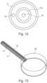
- An embodiment of such a structure is shown in Figure 13
- the first thermal rod and the second thermal rod are configured to be removed from the housing, when the head element is removed. Particularly beneficial is a removal which is possible in a non-destructive and reversible way.
- the first thermal rod and/or the second thermal rod, or a mechanical ensemble which contains both is connected to the housing through a force fitting.
- the housing and the head element are connected by a force-fitting and/or form-fitting, in particular by a threading.
- Other connections may be possible, for example a bayonet lock. This allows to securely connect the head element to the housing.
- the temperature assembly is configured to be connected to the vessel wall by a connection element, in particular by a clamping means.
- the housing is connected via the connection element.
- the connection element may also comprise an adapter element or a receptacle to connect the housing to the connection element.
- a filling material e.g. an insulating material, is at least partially arranged inside of the housing. In an embodiment, it is possible to use air or another gas as filling material.
- a coupling element in particular a pinhole plate, is arranged to the first thermal rod and/or the second thermal rod.
- the coupling element allows to keep the first and second thermal rods thermally decoupled and at a defined spatial space.
- the coupling element also allows to fasten the first and second thermal rods by a force fitting inside the housing. More precisely the coupling element holds the first and/or second thermal rod in position. The coupling element does not inhibit a removal of the rods from the housing.
- the internal cross section of the housing is nowhere smaller than the cross section of the first thermal rod and/or the second thermal rod or the coupling element, for example a pinhole plate.
- the said structures can simply pass every cross section of the housing during removal.
- the inner cross section of the housing is larger, than the cross section of the coupling element.
- the coupling element in particular a pinhole fixed: It may also be oval or of elliptic shape and could be rotated to give a form fitted fixation.
- the coupling element e.g. the pinhole plate, is configured to fit through every cross section of the housing.
- the first thermal rod extends essentially along a middle axis of the housing.
- the second thermal rod extends at least partially parallel to the first thermal rod.
- the first thermal rod/ and/or the second thermal rod is at least in sections. This helps to ensure thermal decoupling of the two thermal rods.
- the bent structure may also help to force fit the thermal rods inside the housing, for example with the help of a coupling element. More specifically, the coupling element may be pressed against an inner surface of the vessel wall because auf the bent shape of the first and/or second thermal rod.
- the first thermal rod and/or the second thermal rod are/is pressed to the surface of the vessel by a spring element.
- the spring elements provide spring-loaded mechanical contacts of the thermal rods. This allows a constant contact pressure of the thermal rods, even when reassembling during maintenance.
- the spring element may comprise an elastic material, for example an elastomer, or a mechanical spring, for example a coil spring. Other suitable materials or components are possible.
- the first thermal rod and/or the second thermal rod comprises a hollow cylindrical shape, wherein the first thermal rod and the second thermal rod are arranged coaxial to each other. In other words, one thermal rod extend coaxially inside the other respective thermal rod.
- the first thermal rod is arranged in a first housing with a first head element and the second thermal rod is arranged in a second housing with a second head element.
- the first housing could also be enclosed by the other (e.g. essentially concentrically or eccentrically)
- a further aspect of the present invention relates to a system for determining a temperature of a surface of a vessel wall, comprising: a temperature sensor assembly according to any of preceding embodiments; and an analysing device, for determining the surface temperature of the vessel wall, wherein the temperature sensor assembly is electrically connected to the analysing device; and a connection element configured to connect the temperature sensor assembly to the vessel wall, wherein the temperature sensor assembly is removable connected to the connection element by an adapter element.
- FIG. 1 illustrates schematically a temperature sensor assembly 10 comprising a housing 11. At an axial end of the housing 11, a head element 12 is arranged. More precisely, the head element 12 is removable arranged or connected to the housing 11.
- the housing 11 may comprise a cylindrical shape or geometry.
- the housing 11 may also be described as neck tube. Alternatively, other shapes may be possible.
- the housing 11 is filled with a filling material 18, in particular an insulating material 18 or gas, for example air. Other gases and/or materials may be possible.
- the head element 12 comprises a first thermal rod 13 and a second thermal rod 15.
- the first and second thermal rods 13, 15 are connected to the head element 12 with an axial end.
- the first thermal rod 13 and the second thermal rod 15 are fixed to the head element 12, such that, in an assembled state, the first and second thermal rods 13,15 both extend inside the housing 11. More precisely, in an assembled state, the two thermal rods 13, 15 are completely surrounded by the housing 11.
- the first and second thermal rods 13, 15 are thermally decoupled from each other.
- the first thermal rod 13 and the second thermal rod 15 extend parallel to each other.
- the first thermal rod 13 and the second thermal rod 15 are connected to the head element 12. When the head element 12 is removed from the housing 11, the first thermal rod 13 and the second thermal rod 15 are also removed from the housing 11.
- the first and second thermal rods 13, 15 may be removed from the housing 11 with the insulating material 18 or without the insulating material 18.
- the first thermal rod 13 and/or the second thermal rod 15 may be loosely hold in place inside the housing 11 by the insulating material or other guiding elements.
- the first thermal rod 13 comprises a temperature measurement sensor 14.
- the temperature measurement sensor 14 is arranged in the area of the free end of the first thermal rod 13.
- the free end of the first thermal rod 13 is in contact with the surface of vessel wall 22.
- the second thermal rod 15 comprises a reference temperature sensor 16.
- the reference temperature sensor 16 is arranged in the area of the free end of the second thermal rod 15.
- the second thermal rod 15 is not in contact with the vessel wall 22.
- the second thermal rod 22 comprises a tip element 24.
- the tip element 24 allows for a different thermal conductivity or thermal resistance between the reference temperature sensor 16 and the vessel wall 22 and the first thermal rod 13 and the vessel wall 22.
- the head element 12 may comprise electronic components for analysing or processing temperature data of the temperature sensors in the first thermal rod 13 and the second thermal rod 15, e.g. the head element 12 may comprise an analysing device.
- the housing 11 is connected to the vessel wall 22 by an adapter element 23.
- the adapter element 23 may be arranged at the vessel wall 22 by a clamp element or a similar structure.
- the adapter element 23 is configured to hold the housing 11 such that the head element 12 with the first thermal rod 13 and the second thermal rod 15 can be removed without removing the housing 11 and/or the adapter element 23.
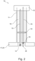
- FIG 2 illustrates another temperature sensor assembly 10.
- the temperature sensor assembly 10 is similar to the one as shown in Figure 1 , but with the difference that a coupling element 19 is arranged at the first thermal rod 13 and the second thermal rod 15. It is possible, that only the first and/or the second thermal rod 13, 15 are connected to the coupling element 19.
- the coupling element 19 allows to keep the first and second thermal rods 13, 15 thermally decoupled.
- the coupling element 19 also allows to fasten the first and second thermal rods 13, 15 by a force fitting inside the housing 11.
- the coupling element 19 may be designed as a pinhole plate 19. Other forms or designs may also be used.
- FIG 3 illustrates another temperature sensor assembly 10.
- the temperature sensor assembly 10 is similar to the one as shown in Figure 2 .
- the first thermal rod 13 extends along a centre longitudinal axis of the housing 11.
- the second thermal rod 15 is arranged eccentric, next to the first thermal rod 13.
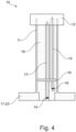
- FIG 4 illustrates another temperature sensor assembly 10.
- the temperature sensor assembly 10 is similar to the one as shown in Figure 3 , but with the difference, that the free end of the second thermal rod 15 comprises a bent or a curvature away from the first thermal rod 13. This is an advantage in terms of thermal decoupling.
- FIG. 5 illustrates another temperature sensor assembly 10.
- the temperature sensor assembly 10 is similar to the one as shown in Figure 2 , but with the difference, that the tip or axial end of the first thermal rod 13 comprises a cap element 25 comprising highly thermal conducting material for improving the thermal coupling between the temperature measurement sensor 14 of the first thermal rod 13 and the surface of the vessel wall 22.
- FIG 6 illustrates a further temperature sensor assembly 10.
- the temperature sensor assembly 10 is similar to the one shown in Figure 5 , but the tip or the free axial end of the second thermal rod 15 is directly thermally coupled to the surface of the vessel wall 22.
- the first thermal rod 13 comprises the cap element 25.
- the cap element 25 has a different thermal conductivity and is beneficial for the thermal decoupling of the second thermal rod 15 from the vessel wall 22.
- the cap element 25 may have a high thermal conductivity for improving the temperature measurement by decreasing the thermal resistance between the surface of the vessel wall 22 and the temperature sensor.
- Figure 7 illustrates a further temperature sensor assembly 10 similar to the temperature sensor assembly 10 as shown in Figure 1 , but wherein the housing 11 is filled only partially with an insulating material 18.
- the insulating material 18 may be used to fix the position of the first and second thermal rods 13, 15. This means, the insulating material 18 may be fixed to the housing 11, but not to the two thermal rods 13, 15.
- the housing 11 is at least partially filled with air.
- the housing 11 is filled with a material whose thermal conductivity is at most a factor of 2 greater than that of air.
- Figure 8 illustrates another temperature sensor assembly 200 similar to the temperature sensor assembly 10 as shown in figure 7 , but without the insulating material.
- two coupling elements 19 are provided, which are only weakly thermally conductive.
- the coupling elements 19 are not connected to the first and second thermal rods 13, 15.
- the first and second thermal rods 13, 15 are guided through respective holes of the coupling element 19 without being fixed/fastened to the coupling element 19.
- the first and the second thermal rods 13, 15, which may be formed as standard thermometer rods are coupled to the surface of the vessel wall 22 mechanically by a spring elements 20 to provide spring-loaded mechanical contacts.
- Figure 9 illustrates another temperature sensor assembly 10, wherein the first thermal rod 13 is arranged within a first housing 11a and the second thermal rod 15 is arranged within a second housing 11b.
- the thermal coupling of the first thermal rod 13 and the thermal coupling of the second thermal rod 15 are each configured as shown in Figure 1 .
- Figure 10 illustrates how the temperature sensor assembly 10 as shown in Figure 9 may be arranged on a curved surface of the vessel wall 22.
- Figure 11 and Figure 12 illustrate an embodiment wherein the first thermal rod 13 and the second thermal rod 15 are arranged in two housings. Inside the housing 11, an inner housing 11c is arranged. The housing 11 and the inner housing 11c are concentrically to each other. The second thermal rod 15 is arranged in the inner housing 11c. The first thermal rod 13 is arranged in an annular gap between the inner housing 11c and the housing 11. More precisely, the first thermal rod 13 is arranged eccentrically from the second thermal rod 15.
- the housing 11 may contain this internal or inner housing 11c with the first and second thermal rods, and possibly one or more other rods.
- the internal or inner housing 11c may be assembled concentrically to the external housing.
- the internal or inner housing 11c may be in mechanical contact to the surface of the vessel wall 22, whose temperature is to be measured, or not.
- Figure 13 and Figure 14 illustrates further embodiments.
- the second thermal rod 15 has a hollow cylindrical geometry, wherein the first thermal rod 13 is arranged concentrically inside the second thermal rod 15.
- the first thermal rod 13 is in contact with a surface of the vessel wall 22.
- the second thermal rod 15 is distanced from the vessel wall 22.
- Figure 14 illustrates the reverse case of Figure 13 .
- the first thermal rod 13 comprises a hollow cylindrical geometry and the second thermal rod 15 is arranged coaxial inside the first thermal rod 13.
- the first thermal rod 13 is in contact with a surface of the vessel wall 22.
- the second thermal rod 15 inside the first thermal rod 13 is distanced to the vessel wall 22.
- Figure 15 illustrates an embodiment, wherein the first thermal rod 13 is bent away from the second thermal rod 15. To put it another way, the first thermal rod 13 and the second thermal rod 15 do not extend along an axis parallel to a longitudinal axis of the housing 11 (the housing is not shown in Figure 15 ).
- the first thermal rod 13 and second thermal rod 15 are bent or inclined towards an inner surface of the housing 11.
- the bent and inclined features allow to create a tension against the housing 11.
- the coupling element 19, which is connected to one or both thermal rods 13, 15 is pressed against an inner surface of the housing 11. This allows to fix the first thermal rod 13 and/or the second thermal rod 15 inside the housing 11 by a force fit.
- the thermal rods 13, 15 are removed with the head element 12.
- the coupling element 19 is also removed with the thermal rods 13, 15, when the head element 12 is removed.
- the head element 12 and the first and second thermal rod 13, 15 with the coupling element 19 can be inserted back into the housing 11 and connected or fastend to it.
Landscapes
- Physics & Mathematics (AREA)
- General Physics & Mathematics (AREA)
- Measuring Temperature Or Quantity Of Heat (AREA)
Abstract
Description
- The present invention relates to a temperature sensor assembly configured to determine a temperature of a surface of a vessel wall, in particular for use in industrial processes. The present invention further relates to a system with such a temperature sensor assembly.
- Determination of temperatures are vital for safe running of facilities, as being one of the main control parameters for process control. Ensuring that temperature measurements of process media are accurate and repeatable is critical. For determination of a temperature of a medium within a vessel and/or of the vessel wall, surface temperature sensors are placed at a surface of a wall of the vessel in order to measure the temperature of this surface, and respectively determine the temperature of the medium at the other side of the wall. Such devices are known for example from
WO2019063519A1 ,WO2020035260A1 ,EP4063815A1 andEP4130694A1 . The surface temperature sensors must be fixed or pressed to the surface in a very reliable and reproducible manner. This is relevant to create a definite thermal contact between wall surface and a thermometer rod or thermal rod, and to have a definite situation for temperature measurement. - It has now become apparent, that there is a need to provide further means for reliable temperature measurements in industrial processes.
- In view of the above, it is an object of the present invention to provide a temperature sensor assembly. It is further an object of the present invention to provide a system with such a temperature sensor assembly.
- These and other objects, which become apparent upon reading the following description, are solved by the subject matter of the independent claims. The dependent claims refer to preferred embodiments of the invention.
- An aspect of the present invention relates to a temperature sensor assembly configured to determine a temperature of a surface of a vessel wall, comprising: a housing and a head element, wherein the head element is removably arranged on the housing. A first thermal rod, comprising a temperature measurement sensor; and/or a second thermal rod, comprising a reference temperature sensor; wherein the first thermal rod and the second thermal rod are connected to the head element, such that the first thermal rod and/or the second thermal rod are removable from the housing with the head element.
- The term "removably" here and in the following means non-destructively, i.e. without damaging any parts, and reversibly, i.e. the part, here the head element, can be put in place again afterwards and is then essentially in the same state as before the removal. Typical options to realize this are thread-type connections, clamps, force fitting. For example, the head element may be removed by loosening a screw joint or a hook, thereby releasing a spring which is pressing the first thermal rod and/or the second thermal rod onto a thermal contact area to make contact to the surface of the vessel wall. Other embodiments, which accomplish the described feature, may also be possible.
- The housing may be connected to the surface of the vessel wall. The housing is connected, pressed and/or attached to the surface, which temperature shall be measured. The housing may be designed as a neck tube. The neck tube may be connected to the vessel wall by an adapter, for example a clamp.
- The first and second thermal rod may e.g. contain sensing elements such as resistive temperature sensors or thermo-couple structures. Additionally, the first and second thermal rod may contain the conductors or wires to operate these sensor elements, together with means to electrically insulate these conductors against each other. Well-known mineral insulated stainless-steel - or copper-clad cables can be embodiments of such a thermal rods, which are well-known to a person skilled in the art.
- The temperature sensor assembly according to the present invention is configured to be used with a surface of a vessel wall. A vessel may be a tube or a tank or a similar object which is designed to contain/carry a fluid. The term "fluid" includes liquid as well as gaseous substances.
- The first thermal rod and the second thermal rod may also be described as thermometer rods. Both thermal rods may be essentially identical in construction. Alternatively, the rods may also be different.
- The first thermal rod comprises the temperature measurement sensor to measure a temperature of the surface of the vessel wall or a temperature close to the surface of the vessel wall. The temperature measurement sensor may also be described as main temperature measurement sensor or contact temperature measurement sensor. The measured temperature may therefore be described as main temperature or contact temperature.
- The second thermal rod comprises the reference temperature sensor to measure a reference temperature, e.g. in a small or a larger distance from the surface. The measured reference temperature can be used together with the main temperature of the temperature measurement sensor of the first thermal rod, to estimate the surface temperature of the vessel wall. If the surface temperature of the vessel wall is known, it may be used to determine the temperature inside the vessel.
- The head element serves as a closure or cover for the housing. Furthermore, the head element may comprise the electronics for evaluating or analysing the measured values of the sensors, e.g. an analysing device, in the first and second thermal rods. A further housing structure configured to house the electronics of the assembly may also be remotely connected to the assembly, in particular the head element.
- The first thermal rod and second thermal rod are both connected to the head element. The first and second thermal rod are not fixated inside the housing. The first and second rod element may be hold in place inside the housing, for example by a force fitting. This may be done by some clamping of the rods themselves inside the housing, or by clamping a coupling element, for example a pinhole plate, inside the housing, which, in turn, can have a form fitted, force-fitted, or welded connection to the first thermal rod and/or second thermal rod.
- A further beneficial force-fitted structure is given by a slightly bent rod structure, either of the first rod and/or of the second rod. An embodiment of such a structure is shown in
Figure 13 - The first thermal rod and the second thermal rod are configured to be removed from the housing, when the head element is removed. Particularly beneficial is a removal which is possible in a non-destructive and reversible way.
- In an embodiment, the first thermal rod and/or the second thermal rod, or a mechanical ensemble which contains both, is connected to the housing through a force fitting.
- In an embodiment, the housing and the head element are connected by a force-fitting and/or form-fitting, in particular by a threading. Other connections may be possible, for example a bayonet lock. This allows to securely connect the head element to the housing.
- In an embodiment, the temperature assembly is configured to be connected to the vessel wall by a connection element, in particular by a clamping means. Preferably, the housing is connected via the connection element. The connection element may also comprise an adapter element or a receptacle to connect the housing to the connection element.
- In an embodiment, a filling material, e.g. an insulating material, is at least partially arranged inside of the housing. In an embodiment, it is possible to use air or another gas as filling material.
- In an embodiment, a coupling element, in particular a pinhole plate, is arranged to the first thermal rod and/or the second thermal rod. The coupling element allows to keep the first and second thermal rods thermally decoupled and at a defined spatial space. The coupling element also allows to fasten the first and second thermal rods by a force fitting inside the housing. More precisely the coupling element holds the first and/or second thermal rod in position. The coupling element does not inhibit a removal of the rods from the housing.
- The internal cross section of the housing is nowhere smaller than the cross section of the first thermal rod and/or the second thermal rod or the coupling element, for example a pinhole plate. The said structures can simply pass every cross section of the housing during removal. In other words, the inner cross section of the housing is larger, than the cross section of the coupling element.
- In order to have the coupling element, in particular a pinhole fixed: It may also be oval or of elliptic shape and could be rotated to give a form fitted fixation. The coupling element, e.g. the pinhole plate, is configured to fit through every cross section of the housing.
- In an embodiment, the first thermal rod extends essentially along a middle axis of the housing.
- In an embodiment, the second thermal rod extends at least partially parallel to the first thermal rod.
- In an embodiment, the first thermal rod/ and/or the second thermal rod is at least in sections. This helps to ensure thermal decoupling of the two thermal rods. The bent structure may also help to force fit the thermal rods inside the housing, for example with the help of a coupling element. More specifically, the coupling element may be pressed against an inner surface of the vessel wall because auf the bent shape of the first and/or second thermal rod.
- In an embodiment, the first thermal rod and/or the second thermal rod are/is pressed to the surface of the vessel by a spring element. The spring elements provide spring-loaded mechanical contacts of the thermal rods. This allows a constant contact pressure of the thermal rods, even when reassembling during maintenance. The spring element may comprise an elastic material, for example an elastomer, or a mechanical spring, for example a coil spring. Other suitable materials or components are possible.
- In an embodiment, the first thermal rod and/or the second thermal rod comprises a hollow cylindrical shape, wherein the first thermal rod and the second thermal rod are arranged coaxial to each other. In other words, one thermal rod extend coaxially inside the other respective thermal rod.
- In an embodiment, the first thermal rod is arranged in a first housing with a first head element and the second thermal rod is arranged in a second housing with a second head element. The first housing could also be enclosed by the other (e.g. essentially concentrically or eccentrically)
- A further aspect of the present invention relates to a system for determining a temperature of a surface of a vessel wall, comprising: a temperature sensor assembly according to any of preceding embodiments; and an analysing device, for determining the surface temperature of the vessel wall, wherein the temperature sensor assembly is electrically connected to the analysing device; and a connection element configured to connect the temperature sensor assembly to the vessel wall, wherein the temperature sensor assembly is removable connected to the connection element by an adapter element.
- The accompanying drawings, which are included to provide a further understanding of the invention and are incorporated in and constitute a part of this application, illustrate embodiments of the invention and together with the description serve to explain the principle of the invention. The drawings display:
- Figure 1
- a schematic drawing of a temperature sensor assembly;
- Figure 2
- a schematic drawing of a another temperature sensor assembly;
- Figure 3
- a schematic drawing of a another temperature sensor assembly;
- Figure 4
- a schematic drawing of a another temperature sensor assembly;
- Figure 5
- a schematic drawing of another temperature sensor assembly;
- Figure 6
- a schematic drawing of another temperature sensor assembly;
- Figure 7
- a schematic drawing of a temperature sensor assembly configured inside of a neck tube;
- Figure 8
- a schematic drawing of a temperature sensor assembly with a spring element;
- Figure 9
- a schematic drawing of a temperature sensor assembly configured with two neck tubes;
- Figure 10
- a schematic drawing of a temperature sensor assembly attached to a pipe/tank perimeter;
- Figure 11
- a schematic drawing of an embodiment of one or more rods in an internal housing;
- Figure 12
- another schematic drawing of the embodiment shown in
Figure 11 ; - Figure 13
- a schematic drawing of an embodiment with a hollow cylindrical thermal rod;
- Figure 14
- a schematic drawing of another embodiment with a hollow cylindrical rod; and
- Figure 15
- a schematic drawing of an assembly of rods which contains one or more bent rods which lead to a certain clamping stress inside the housing after mounting.
-
Figure 1 illustrates schematically atemperature sensor assembly 10 comprising ahousing 11. At an axial end of thehousing 11, ahead element 12 is arranged. More precisely, thehead element 12 is removable arranged or connected to thehousing 11. - The
housing 11 may comprise a cylindrical shape or geometry. Thehousing 11 may also be described as neck tube. Alternatively, other shapes may be possible. Thehousing 11 is filled with a fillingmaterial 18, in particular an insulatingmaterial 18 or gas, for example air. Other gases and/or materials may be possible. - The
head element 12 comprises a firstthermal rod 13 and a secondthermal rod 15. In other words, the first and secondthermal rods head element 12 with an axial end. The firstthermal rod 13 and the secondthermal rod 15 are fixed to thehead element 12, such that, in an assembled state, the first and secondthermal rods housing 11. More precisely, in an assembled state, the twothermal rods housing 11. The first and secondthermal rods thermal rod 13 and the secondthermal rod 15 extend parallel to each other. - The first
thermal rod 13 and the secondthermal rod 15 are connected to thehead element 12. When thehead element 12 is removed from thehousing 11, the firstthermal rod 13 and the secondthermal rod 15 are also removed from thehousing 11. The first and secondthermal rods housing 11 with the insulatingmaterial 18 or without the insulatingmaterial 18. - The first
thermal rod 13 and/or the secondthermal rod 15 may be loosely hold in place inside thehousing 11 by the insulating material or other guiding elements. - The first
thermal rod 13 comprises atemperature measurement sensor 14. Thetemperature measurement sensor 14 is arranged in the area of the free end of the firstthermal rod 13. The free end of the firstthermal rod 13 is in contact with the surface ofvessel wall 22. - The second
thermal rod 15 comprises areference temperature sensor 16. Thereference temperature sensor 16 is arranged in the area of the free end of the secondthermal rod 15. The secondthermal rod 15 is not in contact with thevessel wall 22. The secondthermal rod 22 comprises atip element 24. Thetip element 24 allows for a different thermal conductivity or thermal resistance between thereference temperature sensor 16 and thevessel wall 22 and the firstthermal rod 13 and thevessel wall 22. - The
head element 12 may comprise electronic components for analysing or processing temperature data of the temperature sensors in the firstthermal rod 13 and the secondthermal rod 15, e.g. thehead element 12 may comprise an analysing device. - The
housing 11 is connected to thevessel wall 22 by an adapter element 23. The adapter element 23 may be arranged at thevessel wall 22 by a clamp element or a similar structure. The adapter element 23 is configured to hold thehousing 11 such that thehead element 12 with the firstthermal rod 13 and the secondthermal rod 15 can be removed without removing thehousing 11 and/or the adapter element 23. -
Figure 2 illustrates anothertemperature sensor assembly 10. Thetemperature sensor assembly 10 is similar to the one as shown inFigure 1 , but with the difference that acoupling element 19 is arranged at the firstthermal rod 13 and the secondthermal rod 15. It is possible, that only the first and/or the secondthermal rod coupling element 19. Thecoupling element 19 allows to keep the first and secondthermal rods coupling element 19 also allows to fasten the first and secondthermal rods housing 11. Thecoupling element 19 may be designed as apinhole plate 19. Other forms or designs may also be used. -
Figure 3 illustrates anothertemperature sensor assembly 10. Thetemperature sensor assembly 10 is similar to the one as shown inFigure 2 . The firstthermal rod 13 extends along a centre longitudinal axis of thehousing 11. The secondthermal rod 15 is arranged eccentric, next to the firstthermal rod 13. -
Figure 4 illustrates anothertemperature sensor assembly 10. Thetemperature sensor assembly 10 is similar to the one as shown inFigure 3 , but with the difference, that the free end of the secondthermal rod 15 comprises a bent or a curvature away from the firstthermal rod 13. This is an advantage in terms of thermal decoupling. -
Figure 5 illustrates anothertemperature sensor assembly 10. Thetemperature sensor assembly 10 is similar to the one as shown inFigure 2 , but with the difference, that the tip or axial end of the firstthermal rod 13 comprises acap element 25 comprising highly thermal conducting material for improving the thermal coupling between thetemperature measurement sensor 14 of the firstthermal rod 13 and the surface of thevessel wall 22. -
Figure 6 illustrates a furthertemperature sensor assembly 10. Thetemperature sensor assembly 10 is similar to the one shown inFigure 5 , but the tip or the free axial end of the secondthermal rod 15 is directly thermally coupled to the surface of thevessel wall 22. The firstthermal rod 13 comprises thecap element 25. Thecap element 25 has a different thermal conductivity and is beneficial for the thermal decoupling of the secondthermal rod 15 from thevessel wall 22. Thecap element 25 may have a high thermal conductivity for improving the temperature measurement by decreasing the thermal resistance between the surface of thevessel wall 22 and the temperature sensor. -
Figure 7 illustrates a furthertemperature sensor assembly 10 similar to thetemperature sensor assembly 10 as shown inFigure 1 , but wherein thehousing 11 is filled only partially with an insulatingmaterial 18. The insulatingmaterial 18 may be used to fix the position of the first and secondthermal rods material 18 may be fixed to thehousing 11, but not to the twothermal rods housing 11 is at least partially filled with air. Preferably, thehousing 11 is filled with a material whose thermal conductivity is at most a factor of 2 greater than that of air. -
Figure 8 illustrates another temperature sensor assembly 200 similar to thetemperature sensor assembly 10 as shown infigure 7 , but without the insulating material. To mechanically fix the first and secondthermal rod housing 11, twocoupling elements 19 are provided, which are only weakly thermally conductive. Thecoupling elements 19 are not connected to the first and secondthermal rods thermal rods coupling element 19 without being fixed/fastened to thecoupling element 19. Additionally, the first and the secondthermal rods vessel wall 22 mechanically by aspring elements 20 to provide spring-loaded mechanical contacts. -
Figure 9 illustrates anothertemperature sensor assembly 10, wherein the firstthermal rod 13 is arranged within afirst housing 11a and the secondthermal rod 15 is arranged within asecond housing 11b. The thermal coupling of the firstthermal rod 13 and the thermal coupling of the secondthermal rod 15 are each configured as shown inFigure 1 . -
Figure 10 illustrates how thetemperature sensor assembly 10 as shown inFigure 9 may be arranged on a curved surface of thevessel wall 22. -
Figure 11 andFigure 12 illustrate an embodiment wherein the firstthermal rod 13 and the secondthermal rod 15 are arranged in two housings. Inside thehousing 11, aninner housing 11c is arranged. Thehousing 11 and theinner housing 11c are concentrically to each other. The secondthermal rod 15 is arranged in theinner housing 11c. The firstthermal rod 13 is arranged in an annular gap between theinner housing 11c and thehousing 11. More precisely, the firstthermal rod 13 is arranged eccentrically from the secondthermal rod 15. - In other words, the
housing 11 may contain this internal orinner housing 11c with the first and second thermal rods, and possibly one or more other rods. The internal orinner housing 11c may be assembled concentrically to the external housing. The internal orinner housing 11c may be in mechanical contact to the surface of thevessel wall 22, whose temperature is to be measured, or not. -
Figure 13 andFigure 14 illustrates further embodiments. InFigure 13 the secondthermal rod 15 has a hollow cylindrical geometry, wherein the firstthermal rod 13 is arranged concentrically inside the secondthermal rod 15. The firstthermal rod 13 is in contact with a surface of thevessel wall 22. The secondthermal rod 15 is distanced from thevessel wall 22. -
Figure 14 illustrates the reverse case ofFigure 13 . InFigure 14 , the firstthermal rod 13 comprises a hollow cylindrical geometry and the secondthermal rod 15 is arranged coaxial inside the firstthermal rod 13. The firstthermal rod 13 is in contact with a surface of thevessel wall 22. The secondthermal rod 15 inside the firstthermal rod 13 is distanced to thevessel wall 22. -
Figure 15 illustrates an embodiment, wherein the firstthermal rod 13 is bent away from the secondthermal rod 15. To put it another way, the firstthermal rod 13 and the secondthermal rod 15 do not extend along an axis parallel to a longitudinal axis of the housing 11 (the housing is not shown inFigure 15 ). - In an assembled state, the first
thermal rod 13 and secondthermal rod 15 are bent or inclined towards an inner surface of thehousing 11. The bent and inclined features allow to create a tension against thehousing 11. More precisely, thecoupling element 19, which is connected to one or boththermal rods housing 11. This allows to fix the firstthermal rod 13 and/or the secondthermal rod 15 inside thehousing 11 by a force fit. When thehead element 12 is removed from thehousing 11, thethermal rods head element 12. Thecoupling element 19 is also removed with thethermal rods head element 12 is removed. Thehead element 12 and the first and secondthermal rod coupling element 19 can be inserted back into thehousing 11 and connected or fastend to it. - Other variations to the disclosed embodiments can be understood and effected by those skilled in the art in practicing the claimed invention, from the study of the drawings, the disclosure, and the appended claims. In the claims, the word "comprising" does not exclude other elements or steps and the indefinite article "a" or "an" does not exclude a plurality. A single processor or other unit may fulfill the functions of several items or steps recited in the claims. The mere fact that certain measures are recited in mutually different dependent claims does not indicate that a combination of these measures cannot be used to advantage. Any reference signs in the claims should not be construed as limiting the scope of the claims.
-
- 10
- temperature sensor assembly
- 11
- housing
- 11a
- first housing
- 11b
- second housing
- 11c
- inner housing
- 12
- head element
- 13
- first thermal rod
- 14
- temperature measurement sensor
- 15
- second thermal rod
- 16
- reference temperature sensor
- 17
- connection element
- 18
- filling material/insulating material
- 19
- coupling element
- 20
- spring element
- 22
- vessel wall
- 23
- adapter element
- 24
- tip element
- 25
- cap element
Claims (13)
- A temperature sensor assembly (10) configured to determine a temperature of a surface of a vessel wall (22), comprising:- a housing (11) and a head element (12), wherein the head element (12) is removably arranged on the housing (11);- a first thermal rod (13), comprising a temperature measurement sensor (14); and/or- a second thermal rod (15), comprising a reference temperature sensor (16); wherein- the first thermal rod (13) and the second thermal rod (15) are connected to the head element (12), such that the first thermal rod (13) and/or the second thermal rod (15) are removable from the housing (11) with the head element (12).
- The temperature sensor assembly according to claim 1, wherein the first thermal rod (13) and the second thermal rod (15) are connected to the housing (11) through a force fitting.
- The temperature sensor assembly according to claim 1 or 2, wherein the housing (11) and the head element (12) are connected by a force-fitting and/or form-fitting, in particular by a threading.
- The temperature sensor assembly according to any one of the preceding claims, wherein the temperature assembly (10) is configured to be connected to the vessel wall (22), by a connection element (17), in particular by a clamping means.
- The temperature sensor assembly according to any one of the preceding claims, wherein a filling material (18) is at least partially arranged inside of the housing (11), wherein the filling material (18) is preferably an insulating material (18).
- The temperature sensor assembly according to any one of the preceding claims, wherein a coupling element (19), in particular a pinhole plate (19), is arranged to the first thermal rod (13) and/or the second thermal rod (15).
- The temperature sensor assembly according to any one of the preceding claims, wherein the first thermal rod (13) extends essentially along a middle axis of the housing (11).
- The temperature sensor assembly according to any one of the preceding claims, wherein the second thermal rod (15) extends at least partially parallel to the first thermal rod (13).
- The temperature sensor assembly according to any one of the preceding claims, wherein the first thermal rod (13) and/or the second thermal rod (15) are/is bent at least in sections.
- The temperature sensor assembly according to any one of the preceding claims, wherein the first thermal rod (13) and/or the second thermal rod (15) are/is pressed to the surface of the vessel wall (22) by a spring element (20).
- The temperature assembly according to any one of the preceding claims, wherein, the first thermal rod (13) and/or the second thermal rod (15) comprises a hollow cylindrical shape, wherein the first thermal rod (13) and the second thermal rod (15) are arranged coaxial to each other.
- The temperature sensor assembly according to any one of the preceding claims, wherein the first thermal rod (13) is arranged in a first housing (11a) with a first head element and the second thermal rod (15) is arranged in a second housing (11b) with a second head element.
- A system for determining a temperature of a surface of a vessel wall (22), comprising:- a temperature sensor assembly (10) according to any one of the claims 1 to 12;- an analysing device, for determining the surface temperature of the vessel wall (22), wherein the temperature sensor assembly (10) is electrically connected to the analysing device; and- a connection element (17) configured to connect the temperature sensor assembly (10) to the vessel wall (22); wherein- the temperature sensor assembly (10) is removable connected to the connection element (17) by an adapter element (23).
Priority Applications (3)
| Application Number | Priority Date | Filing Date | Title |
|---|---|---|---|
| EP23170117.8A EP4455626A1 (en) | 2023-04-26 | 2023-04-26 | Temperature sensor assembly |
| CN202410495810.2A CN118857485A (en) | 2023-04-26 | 2024-04-24 | Temperature Sensor Assemblies and Systems |
| US18/644,321 US20240361187A1 (en) | 2023-04-26 | 2024-04-24 | Temperature Sensor Assembly and System |
Applications Claiming Priority (1)
| Application Number | Priority Date | Filing Date | Title |
|---|---|---|---|
| EP23170117.8A EP4455626A1 (en) | 2023-04-26 | 2023-04-26 | Temperature sensor assembly |
Publications (1)
| Publication Number | Publication Date |
|---|---|
| EP4455626A1 true EP4455626A1 (en) | 2024-10-30 |
Family
ID=86226835
Family Applications (1)
| Application Number | Title | Priority Date | Filing Date |
|---|---|---|---|
| EP23170117.8A Pending EP4455626A1 (en) | 2023-04-26 | 2023-04-26 | Temperature sensor assembly |
Country Status (3)
| Country | Link |
|---|---|
| US (1) | US20240361187A1 (en) |
| EP (1) | EP4455626A1 (en) |
| CN (1) | CN118857485A (en) |
Citations (5)
| Publication number | Priority date | Publication date | Assignee | Title |
|---|---|---|---|---|
| WO2019063519A1 (en) | 2017-09-27 | 2019-04-04 | Abb Schweiz Ag | TEMPERATURE MEASURING DEVICE AND METHOD FOR TEMPERATURE DETERMINATION |
| WO2020035260A1 (en) | 2018-08-15 | 2020-02-20 | Abb Schweiz Ag | Temperature measuring device and method for determining temperature |
| EP4063815A1 (en) | 2021-03-23 | 2022-09-28 | ABB Schweiz AG | Temperature-measuring device |
| EP4130694A1 (en) | 2021-08-02 | 2023-02-08 | Abb Schweiz Ag | A temperature sensor assembly |
| DE102021209278A1 (en) * | 2021-08-24 | 2023-03-02 | Siemens Aktiengesellschaft | Temperature measuring device for non-invasive temperature measurement, calibration method and computer program product |
-
2023
- 2023-04-26 EP EP23170117.8A patent/EP4455626A1/en active Pending
-
2024
- 2024-04-24 CN CN202410495810.2A patent/CN118857485A/en active Pending
- 2024-04-24 US US18/644,321 patent/US20240361187A1/en active Pending
Patent Citations (5)
| Publication number | Priority date | Publication date | Assignee | Title |
|---|---|---|---|---|
| WO2019063519A1 (en) | 2017-09-27 | 2019-04-04 | Abb Schweiz Ag | TEMPERATURE MEASURING DEVICE AND METHOD FOR TEMPERATURE DETERMINATION |
| WO2020035260A1 (en) | 2018-08-15 | 2020-02-20 | Abb Schweiz Ag | Temperature measuring device and method for determining temperature |
| EP4063815A1 (en) | 2021-03-23 | 2022-09-28 | ABB Schweiz AG | Temperature-measuring device |
| EP4130694A1 (en) | 2021-08-02 | 2023-02-08 | Abb Schweiz Ag | A temperature sensor assembly |
| DE102021209278A1 (en) * | 2021-08-24 | 2023-03-02 | Siemens Aktiengesellschaft | Temperature measuring device for non-invasive temperature measurement, calibration method and computer program product |
Also Published As
| Publication number | Publication date |
|---|---|
| CN118857485A (en) | 2024-10-29 |
| US20240361187A1 (en) | 2024-10-31 |
Similar Documents
| Publication | Publication Date | Title |
|---|---|---|
| EP2559987B1 (en) | Combination pressure/temperature in a compact sensor assembly | |
| US12442693B2 (en) | Temperature sensor assembly | |
| EP2420807B1 (en) | Temperature sensor | |
| CN1228836A (en) | Automatic verification of temperature sensors | |
| US20040164868A1 (en) | Carbon dioxide fire extinguishing device | |
| EP2023106A2 (en) | Improved thermocouple head terminal | |
| US11994421B2 (en) | Vibration resistant temperature sensing assembly | |
| EP3563130B1 (en) | Adjustable spring loaded adapter for temperature sensor | |
| CN105675728A (en) | Super-high-temperature electromagnetic acoustic sensor and obtaining method thereof | |
| US3526134A (en) | Thermobulb mount | |
| EP4455626A1 (en) | Temperature sensor assembly | |
| JPH0569635U (en) | Liquid level sensor | |
| WO2006037992A1 (en) | Apparatus and method for measuring hydrogen concentration in molten metals | |
| US10481060B2 (en) | Density sensor and density sensor manufacturing method | |
| RU2633405C1 (en) | Device for measuring thermal conductivity | |
| RU2099675C1 (en) | Resistance thermometer for measurement of temperature of liquid and gaseous media in pipe lines | |
| US20230147830A1 (en) | Coupling adapter for a thermometer | |
| US2988718A (en) | Detecting probe | |
| RU2327122C1 (en) | Temperature sensor | |
| EP3557207A2 (en) | Coaxial high temperature thermocouple | |
| CN220019442U (en) | Freezing point tester for crystal substance | |
| CN220381070U (en) | Detection device for liquid chromatography system | |
| US9188494B2 (en) | Measurement of fluid temperatures | |
| EP4641155A1 (en) | Non-invasive temperature sensor | |
| JPH09273957A (en) | Level measuring apparatus |
Legal Events
| Date | Code | Title | Description |
|---|---|---|---|
| PUAI | Public reference made under article 153(3) epc to a published international application that has entered the european phase |
Free format text: ORIGINAL CODE: 0009012 |
|
| STAA | Information on the status of an ep patent application or granted ep patent |
Free format text: STATUS: THE APPLICATION HAS BEEN PUBLISHED |
|
| AK | Designated contracting states |
Kind code of ref document: A1 Designated state(s): AL AT BE BG CH CY CZ DE DK EE ES FI FR GB GR HR HU IE IS IT LI LT LU LV MC ME MK MT NL NO PL PT RO RS SE SI SK SM TR |
|
| STAA | Information on the status of an ep patent application or granted ep patent |
Free format text: STATUS: REQUEST FOR EXAMINATION WAS MADE |
|
| 17P | Request for examination filed |
Effective date: 20250409 |
|
| STAA | Information on the status of an ep patent application or granted ep patent |
Free format text: STATUS: EXAMINATION IS IN PROGRESS |
|
| 17Q | First examination report despatched |
Effective date: 20251008 |