EP4455617A1 - Shape measurement system and shape measurement method - Google Patents
Shape measurement system and shape measurement method Download PDFInfo
- Publication number
- EP4455617A1 EP4455617A1 EP22910773.5A EP22910773A EP4455617A1 EP 4455617 A1 EP4455617 A1 EP 4455617A1 EP 22910773 A EP22910773 A EP 22910773A EP 4455617 A1 EP4455617 A1 EP 4455617A1
- Authority
- EP
- European Patent Office
- Prior art keywords
- optical fiber
- core optical
- shape
- strain
- strain distribution
- Prior art date
- Legal status (The legal status is an assumption and is not a legal conclusion. Google has not performed a legal analysis and makes no representation as to the accuracy of the status listed.)
- Pending
Links
Images





Classifications
-
- G—PHYSICS
- G01—MEASURING; TESTING
- G01B—MEASURING LENGTH, THICKNESS OR SIMILAR LINEAR DIMENSIONS; MEASURING ANGLES; MEASURING AREAS; MEASURING IRREGULARITIES OF SURFACES OR CONTOURS
- G01B11/00—Measuring arrangements characterised by the use of optical techniques
- G01B11/16—Measuring arrangements characterised by the use of optical techniques for measuring the deformation in a solid, e.g. optical strain gauge
- G01B11/18—Measuring arrangements characterised by the use of optical techniques for measuring the deformation in a solid, e.g. optical strain gauge using photoelastic elements
-
- G—PHYSICS
- G01—MEASURING; TESTING
- G01B—MEASURING LENGTH, THICKNESS OR SIMILAR LINEAR DIMENSIONS; MEASURING ANGLES; MEASURING AREAS; MEASURING IRREGULARITIES OF SURFACES OR CONTOURS
- G01B11/00—Measuring arrangements characterised by the use of optical techniques
- G01B11/16—Measuring arrangements characterised by the use of optical techniques for measuring the deformation in a solid, e.g. optical strain gauge
-
- G—PHYSICS
- G01—MEASURING; TESTING
- G01D—MEASURING NOT SPECIALLY ADAPTED FOR A SPECIFIC VARIABLE; ARRANGEMENTS FOR MEASURING TWO OR MORE VARIABLES NOT COVERED IN A SINGLE OTHER SUBCLASS; TARIFF METERING APPARATUS; MEASURING OR TESTING NOT OTHERWISE PROVIDED FOR
- G01D5/00—Mechanical means for transferring the output of a sensing member; Means for converting the output of a sensing member to another variable where the form or nature of the sensing member does not constrain the means for converting; Transducers not specially adapted for a specific variable
- G01D5/26—Mechanical means for transferring the output of a sensing member; Means for converting the output of a sensing member to another variable where the form or nature of the sensing member does not constrain the means for converting; Transducers not specially adapted for a specific variable characterised by optical transfer means, i.e. using infrared, visible, or ultraviolet light
- G01D5/32—Mechanical means for transferring the output of a sensing member; Means for converting the output of a sensing member to another variable where the form or nature of the sensing member does not constrain the means for converting; Transducers not specially adapted for a specific variable characterised by optical transfer means, i.e. using infrared, visible, or ultraviolet light with attenuation or whole or partial obturation of beams of light
- G01D5/34—Mechanical means for transferring the output of a sensing member; Means for converting the output of a sensing member to another variable where the form or nature of the sensing member does not constrain the means for converting; Transducers not specially adapted for a specific variable characterised by optical transfer means, i.e. using infrared, visible, or ultraviolet light with attenuation or whole or partial obturation of beams of light the beams of light being detected by photocells
- G01D5/353—Mechanical means for transferring the output of a sensing member; Means for converting the output of a sensing member to another variable where the form or nature of the sensing member does not constrain the means for converting; Transducers not specially adapted for a specific variable characterised by optical transfer means, i.e. using infrared, visible, or ultraviolet light with attenuation or whole or partial obturation of beams of light the beams of light being detected by photocells influencing the transmission properties of an optical fibre
- G01D5/3537—Optical fibre sensor using a particular arrangement of the optical fibre itself
- G01D5/3538—Optical fibre sensor using a particular arrangement of the optical fibre itself using a particular type of fiber, e.g. fibre with several cores, PANDA fiber, fiber with an elliptic core or the like
-
- G—PHYSICS
- G02—OPTICS
- G02B—OPTICAL ELEMENTS, SYSTEMS OR APPARATUS
- G02B6/00—Light guides; Structural details of arrangements comprising light guides and other optical elements, e.g. couplings
- G02B6/02—Optical fibres with cladding with or without a coating
- G02B6/02042—Multicore optical fibres
-
- G—PHYSICS
- G02—OPTICS
- G02B—OPTICAL ELEMENTS, SYSTEMS OR APPARATUS
- G02B6/00—Light guides; Structural details of arrangements comprising light guides and other optical elements, e.g. couplings
- G02B6/24—Coupling light guides
- G02B6/42—Coupling light guides with opto-electronic elements
- G02B6/4201—Packages, e.g. shape, construction, internal or external details
- G02B6/4202—Packages, e.g. shape, construction, internal or external details for coupling an active element with fibres without intermediate optical elements, e.g. fibres with plane ends, fibres with shaped ends, bundles
Definitions
- the present disclosure relates to a technique for deriving a three-dimensional shape of a measuring object on the basis of measurement and analysis of a strain distribution in a light propagation direction of a multi-core optical fiber installed along the measuring object.
- a reflection spectrum in a frequency domain of each core of a multi-core optical fiber (hereinafter sometimes referred to as MCF (Multi Core Fiber).) is measured by optical frequency domain reflectometry (OFDR), and a measurement result is analyzed, so that a three-dimensional shape of a measuring object can be derived (see, for example, Non Patent Literatures 1 and 2.).
- OFDR optical frequency domain reflectometry
- a measurement distance is limited to about several tens of meters.
- a method for improving measurement resolution by applying fiber bragg gratings (FBG) to the entire length of a sensing medium is known (see, for example, Non Patent Literature 1.).
- FBG fiber bragg gratings
- shape identification can also be performed using quasi-distribution measurement by application of FBGs or the like (see, for example, Non Patent Literature 2.).
- FBGs frequency division multiplexing
- this technique has the problem that the number of measurement points is limited and shape identification over a long distance is difficult to perform.
- Non Patent Literature 3 uses Brillouin optical time domain reflectometry (BOTDR) capable of measurement over a long distance ranging from several kilometers to several tens of kilometers.
- BOTDR Brillouin optical time domain reflectometry
- Non Patent Literature 3 requires a core at the center of a cladding of the MCF, and thus it is impossible to use a four-core fiber having no core at the center of a cladding used for communication.
- Non Patent Literature 3 it is necessary to increase a distance between a central core and a peripheral core for shape sensing with a small curvature.
- a cladding diameter is increased in order to increase the core interval, a problem occurs in which breakage due to bending of the optical fiber is likely to occur.
- An object of the present disclosure is to achieve shape identification of a measuring object over a long distance using a multi-core optical fiber having no core at the center of a cladding.
- a shape measurement system of the present disclosure includes:
- a shape measurement method of the present disclosure includes:
- the present disclosure can achieve shape identification of a measuring object over a long distance using a multi-core optical fiber having no core at the center of a cladding.
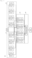
- Fig. 1 illustrates an example of a system configuration of the present disclosure.
- a system that achieves a shape identification method of the present disclosure includes a multi-core optical fiber 91 used for extracting a shape change of a measuring object 100, a strain distribution measurement device 92 that detects a strain distribution in a propagation direction of each core 11 of the multi-core optical fiber 91, and an analysis device 93 that analyzes measurement data acquired by the strain distribution measurement device 92.
- the multi-core optical fiber 91 is installed along a longitudinal direction of the measuring object 100.
- the multi-core optical fiber 91 includes a total of four cores 11 disposed in a cladding 12.
- the four cores 11 are disposed on a square lattice at substantially equal intervals on substantially the same circumference at a distance r from the cross-sectional center of the cladding 12, in a region other than the cross-sectional center of the cladding 12.
- the cores 11 included in the MCF 91 may have a structure in which the cores are disposed so as to intentionally make their refractive index distributions and optical characteristics different.
- the exemplary embodiment of the present disclosure shows an example in which the number of cores 11 is four, the number of cores 11 may be four or more.
- the cores 11 of the MCF 91 may be disposed at intervals that are not the equal intervals, but it is preferable that the cores 11 are disposed equally to some extent in the cross section of the MCF 91. For example, when the number of cores is four, the cores may be separately disposed in four quadrants in an orthogonal coordinate.
- a change in an extending state of the MCF 91 is detected using an MCF in which a cladding outer diameter is set to 125 um and a core interval is set to 35 um to 45 um in order to reduce crosstalk between the cores.
- a strain distribution measurement device 92 a BOTDR device that measures a backward Brillouin scattering light distribution is used.
- Fig. 2 illustrates an example of a flow executed in the shape identification method of the present disclosure.
- the MCF 91 is laid on the measuring object 100, and the strain distribution characteristic of each core 11 in a steady state is acquired using the strain distribution measurement device 92 (step S1).
- the analysis device 93 acquires a strain distribution in a reference shape of the MCF 91.
- the strain distribution characteristic of each core 11 is acquired again using the strain distribution measurement device 92 (step S2).
- the analysis device 93 acquires a strain distribution in an unknown shape of the MCF 91.
- step S3 a differential strain in step S2 with respect to step S1 is derived at each point of the MCF 91 where the strain distribution measurement device 92 measures a strain (step S3).
- a differential strain ⁇ i thus calculated in step S3 is the sum of a strain ⁇ b due to bending of the MCF 91 and an axial strain ⁇ a in the longitudinal direction of the MCF 91.
- r represents a distance from a central axis C c of the cladding 12 to the core 11
- ⁇ i represents an angle of the core 11 in the cross section of the MCF 91.
- Fig. 4 illustrates a specific example of the distance r, the angle ⁇ , and the bending angle ⁇ .
- An angle ⁇ 1 is an angle formed between a line connecting a core C1 and the central axis C c of the MCF 91 and a line connecting a core C4 adjacent to the core C1 and the central axis C c of the MCF 91.
- the angles ⁇ 1 to ⁇ 4 are 90 degrees.
- step S3 since there are four cores 11, quartic simultaneous equations are obtained.
- the axial strain ⁇ a , the curvature ⁇ in the bending strain, and the bending angle ⁇ are equal in any core 11. Therefore, the differential strain ⁇ i of each core 11 is obtained using the least squares method or the like. (step S3)
- a position vector of the magnitude, corresponding to the differential strain ⁇ i , in a direction corresponding to the curvature ⁇ and the bending angle ⁇ at each point of a distance z where the strain is measured is determined using the Frenet-Serret integral formula (step S4).
- position accuracy can be improved by correcting a start point and an end point of a measured section in the distance z of the multi-core optical fiber 91.
- BOTDR optical frequency domain reflectometry
- OFDR optical frequency domain reflectometry
- Figs. 5A to 5C illustrate an extraction example of a three-dimensional shape change in the exemplary embodiment of the present disclosure.
- the strain distribution data in the reference shape in step S1 of Fig. 2 was acquired in a state where the MCF 91 for sensing was linearly extended.
- step S2 was executed by making one loop at a constant curvature on an xy plane counterclockwise so that the measuring object 100 was disposed in the middle of the MCF 91 as illustrated in Fig. 5A .
- the strain distribution data in the unknown shape in Fig. 5B was acquired.
- Solid lines C1, C2, C3, and C4 in Fig. 5B represents difference among their respective core numbers i. Fig.
- 5C illustrates a result of shape identification by calculating the shape of the MCF 91 changed from the reference shape on the basis of the strain distribution data in steps S1 and S2. From this result, it can be seen that the curvature of the bending in the middle of the measuring object 100 can be accurately detected.
- Figs. 6A to 6C illustrate an extraction example of the three-dimensional shape change in the exemplary embodiment of the present disclosure.
- the strain distribution data in the reference shape in step S1 of Fig. 2 was acquired in a state where the MCF 91 for sensing was linearly extended.
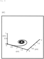
- step S2 was executed by deforming the end part of the MCF 91 along the measuring object 100 that spirals on an xy plane as illustrated in Fig. 6A .
- the strain distribution data in the unknown shape in Fig. 6B was acquired.
- Solid lines C1, C2, C3, and C4 in Fig. 6B represents difference among their respective core numbers i. Fig.
- 6C illustrates a result of shape identification by calculating the shape of the MCF 91 changed from the reference shape on the basis of the strain distribution data in steps S1 and S2. From this result, it can be seen that the shape change in which the curvature gradually decreases to the end side of the MCF 91 can be accurately detected.
- Fig. 7 illustrates an example of the amount of strain generated in the core 11 with respect to the distance r.
- Difference in line type in Fig. 7 represents difference in curvature, and it can be seen that increase in the distance r from the central axis C c of the cladding 12 to the core 11 causes increase in the amount of strain, and a minute change is more easily extracted.
- the MCF 91 in order to increase the distance r between the central axis C c of the cladding 12 and the center of the core 11, it is necessary to increase the diameter of the cladding 12. As the cladding diameter is increased, the rigidity of the optical fiber increases, the optical fiber itself is more difficult to bend, and the possibility of breakage also increases.
- the rigidity of the optical fiber depends on a cross-sectional shape of the optical fiber, and a solid optical fiber in which the entire optical fiber is glass, as illustrated in Fig. 8A , has a section modulus expressed by Formula (3).
- the present disclosure does not require the core 11 at the cladding central axis C c and can thereby adopt a hollow optical fiber, in which the central axis C c of the cladding 12 is hollow as illustrated in Fig. 8B .
- a section modulus in this instance is expressed by Formula (4). [Numerical Formula 4] ⁇ 32 R 4 ⁇ R a 4 R
- Fig. 8C illustrates the section moduli with respect to the diameter of the cladding 12 calculated using Formulas (3) and (4).
- Non Patent Literature 3 discloses that it is possible to perform shape identification without breakage in an MCF in which the cladding 12 has a diameter of 375 um. It can be understood that setting the hollow area to 80% can keep the same level of rigidity, with the cladding 12 even having a diameter of 430 ⁇ m, as that of the cladding 12 having a diameter of 375 um. Since the hollow MCF is usable in the present disclosure, the distance r from the cladding central axis C c to the core 11 can be increased as compared with the solid type illustrated in Fig. 8A . Therefore, the present disclosure can detect a minute amount of strain.
- a system configuration of a shape measurement system of the present embodiment is different from the configuration described with reference to Fig. 1 in that the known twists are applied to the MCF 91, and in addition, an analysis procedure of the analysis device 93 related thereto is different. Specifically, a shape measurement method of the present embodiment is different therefrom in the analysis in steps S3 and S4 illustrated in Fig. 2 .
- the differential strain ⁇ i obtained by finding the difference between the strain distribution of each core 11 in the unknown shape and the strain distribution of each core 11 in the reference shape, is expressed by the sum of the bending strain ⁇ b,i and the axial strain ⁇ a .
- the differential strain ⁇ i is the sum of the bending strain ⁇ b,i , the axial strain ⁇ a , and a twisting strain ⁇ t .
- the bending strain ⁇ b,i of Formula (1) is expressed by Formula (5), and respective coefficients are expressed by (6) to (9).
- k 1 and k 2 are correction coefficients for the twisting
- ⁇ i is an angle indicating the position of the core number i
- ⁇ is a Poisson's ratio
- p is a spin rate of the core 11 on the circumference
- ⁇ is a specific angle of twist.
- the spin rate is the number of twists applied to the MCF 91 [times/m].
- the curvature ⁇ , the bending angle ⁇ , the axial strain ⁇ a , and the twisting strain ⁇ t satisfying Formulas (5) and (10) are determined by the least squares method or the like (step S4).
- a position vector of the magnitude, corresponding to the differential strain ⁇ i of the multi-core optical fiber, in a direction corresponding to the curvature ⁇ and the bending angle ⁇ at each point of a distance z where the strain is measured is determined using the Frenet-Serret integral formula.
- the present disclosure enables shape identification by using the core disposition structure in which there is no core at the center of the multi-core optical fiber used for detecting a shape change.
- shape identification over several tens of meters is performed in OFDR, whereas shape identification over several kilometers or several tens of kilometers is enabled.
- a hollow optical fiber is usable as the MCF 91, it is practical to increase the strain and improve the measurement sensitivity enough to measure a minute shape, by increasing the outer diameter of the MCF and increasing the distance between the cladding center and the core center.
- the present disclosure can be used for measures against infrastructure aging by deriving a three-dimensional shape of a measuring object.
Landscapes
- Physics & Mathematics (AREA)
- General Physics & Mathematics (AREA)
- Length Measuring Devices By Optical Means (AREA)
Abstract
Description
- The present disclosure relates to a technique for deriving a three-dimensional shape of a measuring object on the basis of measurement and analysis of a strain distribution in a light propagation direction of a multi-core optical fiber installed along the measuring object.
- A reflection spectrum in a frequency domain of each core of a multi-core optical fiber (hereinafter sometimes referred to as MCF (Multi Core Fiber).) is measured by optical frequency domain reflectometry (OFDR), and a measurement result is analyzed, so that a three-dimensional shape of a measuring object can be derived (see, for example,
Non Patent Literatures - A method for improving measurement resolution by applying fiber bragg gratings (FBG) to the entire length of a sensing medium is known (see, for example,
Non Patent Literature 1.). However, there is the problem that the manufacturability and economic efficiency of the sensing medium are deteriorated. - On the other hand, shape identification can also be performed using quasi-distribution measurement by application of FBGs or the like (see, for example,
Non Patent Literature 2.). However, this technique has the problem that the number of measurement points is limited and shape identification over a long distance is difficult to perform. - In addition, shape identification using an MCF has also been proposed (see, for example,
Non Patent Literature 3.).Non Patent Literature 3 uses Brillouin optical time domain reflectometry (BOTDR) capable of measurement over a long distance ranging from several kilometers to several tens of kilometers. However,Non Patent Literature 3 requires a core at the center of a cladding of the MCF, and thus it is impossible to use a four-core fiber having no core at the center of a cladding used for communication. - Furthermore, in
Non Patent Literature 3, it is necessary to increase a distance between a central core and a peripheral core for shape sensing with a small curvature. However, when a cladding diameter is increased in order to increase the core interval, a problem occurs in which breakage due to bending of the optical fiber is likely to occur. -
- Non Patent Literature 1: https://doi.org/10.1117/12.720914 (High-accuracy fiber-optic shape sensing)
- Non Patent Literature 2: DOI:10.1109/TMECH.2010.2080360 (Real-Time Estimation of 3-D Needle Shape and Deflection for MRI-Guided Interventions)
- Non Patent Literature 3: Kobayashi et al., "Basic Study of Shape Sensing for Large-Scale Line Structures with Multi-Core Fibers by Brillouin OTDR", OFT 2020-19, 2020.
- An object of the present disclosure is to achieve shape identification of a measuring object over a long distance using a multi-core optical fiber having no core at the center of a cladding.
- Specifically, a shape measurement system of the present disclosure includes:
- a multi-core optical fiber in which four or more cores are disposed in a part other than the center of a cross section;
- a strain distribution measurement device configured to measure a strain distribution of each of the cores in a longitudinal direction of the multi-core optical fiber; and
- an analysis device configured to calculate a shape of the multi-core optical fiber by using the strain distribution of the multi-core optical fiber.
- Specifically, a shape measurement method of the present disclosure includes:
- using a multi-core optical fiber in which four or more cores are disposed in a part other than the center of a cross section and measuring, by means of a strain distribution measurement device, a strain distribution of each of the cores in a longitudinal direction of the multi-core optical fiber; and
- calculating, by means of an analysis device, a shape of the multi-core optical fiber by using the strain distribution of the multi-core optical fiber.
- The present disclosure can achieve shape identification of a measuring object over a long distance using a multi-core optical fiber having no core at the center of a cladding.
-
-
Fig. 1 illustrates an example of a system configuration of the present disclosure. -
Fig. 2 illustrates an example of a flow executed by a system of the present disclosure. -
Fig. 3 is an explanatory diagram of a curvature κ in the present disclosure. -
Fig. 4 is an explanatory diagram of a distance r, an angle α, and a bending angle β in the present disclosure. -
Fig. 5A illustrates a first extraction example of a three-dimensional shape change in an exemplary embodiment of the present disclosure. -
Fig. 5B illustrates the first extraction example of the three-dimensional shape change in the exemplary embodiment of the present disclosure. -
Fig. 5C illustrates the first extraction example of the three-dimensional shape change in the exemplary embodiment of the present disclosure. -
Fig. 6A illustrates a second extraction example of the three-dimensional shape change in the exemplary embodiment of the present disclosure. -
Fig. 6B illustrates the second extraction example of the three-dimensional shape change in the exemplary embodiment of the present disclosure. -
Fig. 6C illustrates the second extraction example of the three-dimensional shape change in the exemplary embodiment of the present disclosure. -
Fig. 7 illustrates an example of the distance r and a strain amount generated in a core. -
Fig. 8A illustrates a cross-sectional structure example of a solid optical fiber. -
Fig. 8B illustrates a cross-sectional structure example of a hollow optical fiber. -
Fig. 8C illustrates an example of a section modulus with respect to a cladding diameter. -
Fig. 9 illustrates an example of an MCF used in an exemplary embodiment of the present disclosure. - Hereinafter, embodiments of the present disclosure will be described in detail with reference to the drawings. Note that the present disclosure is not limited to the following embodiments. These embodiments are merely examples, and the present disclosure can be implemented in a form with various modifications and improvements applied on the basis of the knowledge of a person skilled in the art. Note that components having the same reference numerals in the present specification and the drawings indicate the same components.
-
Fig. 1 illustrates an example of a system configuration of the present disclosure. - A system that achieves a shape identification method of the present disclosure includes a multi-core
optical fiber 91 used for extracting a shape change of ameasuring object 100, a straindistribution measurement device 92 that detects a strain distribution in a propagation direction of eachcore 11 of the multi-coreoptical fiber 91, and ananalysis device 93 that analyzes measurement data acquired by the straindistribution measurement device 92. - The multi-core
optical fiber 91 is installed along a longitudinal direction of themeasuring object 100. The multi-coreoptical fiber 91 includes a total of fourcores 11 disposed in acladding 12. In the drawing, as an embodiment example, an example is illustrated in which the fourcores 11 are disposed on a square lattice at substantially equal intervals on substantially the same circumference at a distance r from the cross-sectional center of thecladding 12, in a region other than the cross-sectional center of thecladding 12. - In the exemplary embodiment of the present disclosure, an example in which the four
cores 11 have substantially the same refractive index distribution and optical characteristic will be described. However, thecores 11 included in theMCF 91 may have a structure in which the cores are disposed so as to intentionally make their refractive index distributions and optical characteristics different. In addition, although the exemplary embodiment of the present disclosure shows an example in which the number ofcores 11 is four, the number ofcores 11 may be four or more. In addition, thecores 11 of theMCF 91 may be disposed at intervals that are not the equal intervals, but it is preferable that thecores 11 are disposed equally to some extent in the cross section of theMCF 91. For example, when the number of cores is four, the cores may be separately disposed in four quadrants in an orthogonal coordinate. - In the
MCF 91 of the exemplary embodiment of the present disclosure, a change in an extending state of theMCF 91 is detected using an MCF in which a cladding outer diameter is set to 125 um and a core interval is set to 35 um to 45 um in order to reduce crosstalk between the cores. In addition, as the straindistribution measurement device 92, a BOTDR device that measures a backward Brillouin scattering light distribution is used.Fig. 2 illustrates an example of a flow executed in the shape identification method of the present disclosure. - First, the
MCF 91 is laid on the measuringobject 100, and the strain distribution characteristic of each core 11 in a steady state is acquired using the strain distribution measurement device 92 (step S1). As a result, theanalysis device 93 acquires a strain distribution in a reference shape of theMCF 91. - Next, in a state where a three-dimensional shape of the measuring
object 100 has changed, the strain distribution characteristic of each core 11 is acquired again using the strain distribution measurement device 92 (step S2). As a result, theanalysis device 93 acquires a strain distribution in an unknown shape of theMCF 91. - Next, using the data acquired in step S1 and the data acquired in step S2, a differential strain in step S2 with respect to step S1 is derived at each point of the
MCF 91 where the straindistribution measurement device 92 measures a strain (step S3). A differential strain εi thus calculated in step S3 is the sum of a strain εb due to bending of theMCF 91 and an axial strain εa in the longitudinal direction of theMCF 91. - When the
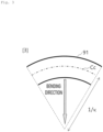
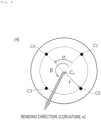
MCF 91 is bent as illustrated inFig. 3 , a bending strain εb,i, a curvature κ, and a bending angle β in each core Ci (i = 1 to 4) are expressed by Relational Formula (1).
- Note that r represents a distance from a central axis Cc of the
cladding 12 to thecore 11, and αi represents an angle of the core 11 in the cross section of theMCF 91. -
Fig. 4 illustrates a specific example of the distance r, the angle α, and the bending angle β. An angle α1 is an angle formed between a line connecting a core C1 and the central axis Cc of theMCF 91 and a line connecting a core C4 adjacent to the core C1 and the central axis Cc of theMCF 91. In the present embodiment, since the cores C1 to C4 are disposed at substantially equal intervals on the concentric circle, the angles α1 to α4 are 90 degrees. - Here, the axial strain εa is uniformly generated with respect to the cross section of the
MCF 91, and thus is constant regardless of the core number i. Therefore, the differential strain εi at the core number i calculated in step S3 is expressed by Formula (2).
- In the present embodiment, since there are four
cores 11, quartic simultaneous equations are obtained. In addition, the axial strain εa, the curvature κ in the bending strain, and the bending angle β are equal in anycore 11. Therefore, the differential strain εi of each core 11 is obtained using the least squares method or the like. (step S3) - Finally, a position vector of the magnitude, corresponding to the differential strain εi, in a direction corresponding to the curvature κ and the bending angle β at each point of a distance z where the strain is measured is determined using the Frenet-Serret integral formula (step S4). As a result, it is practical to obtain direction and extent of deformation at each point of the distance z of the multi-core
optical fiber 91, and thus it is practical to measure the shape of the multi-coreoptical fiber 91 after deformation from the steady state. - Note that position accuracy can be improved by correcting a start point and an end point of a measured section in the distance z of the multi-core
optical fiber 91. In addition, although the BOTDR is used for the strain distribution measurement in the present exemplary embodiment, any means capable of measuring a strain of an optical fiber such as optical frequency domain reflectometry (OFDR) may be used. -
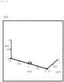
Figs. 5A to 5C illustrate an extraction example of a three-dimensional shape change in the exemplary embodiment of the present disclosure. In the exemplary embodiment of the present disclosure, the strain distribution data in the reference shape in step S1 ofFig. 2 was acquired in a state where theMCF 91 for sensing was linearly extended. Next, step S2 was executed by making one loop at a constant curvature on an xy plane counterclockwise so that the measuringobject 100 was disposed in the middle of theMCF 91 as illustrated inFig. 5A . As a result, the strain distribution data in the unknown shape inFig. 5B was acquired. Solid lines C1, C2, C3, and C4 inFig. 5B represents difference among their respective core numbers i.Fig. 5C illustrates a result of shape identification by calculating the shape of theMCF 91 changed from the reference shape on the basis of the strain distribution data in steps S1 and S2. From this result, it can be seen that the curvature of the bending in the middle of the measuringobject 100 can be accurately detected. -
Figs. 6A to 6C illustrate an extraction example of the three-dimensional shape change in the exemplary embodiment of the present disclosure. Similarly to the example ofFigs. 5A to 5C , the strain distribution data in the reference shape in step S1 ofFig. 2 was acquired in a state where theMCF 91 for sensing was linearly extended. Next, step S2 was executed by deforming the end part of theMCF 91 along the measuringobject 100 that spirals on an xy plane as illustrated inFig. 6A . As a result, the strain distribution data in the unknown shape inFig. 6B was acquired. Solid lines C1, C2, C3, and C4 inFig. 6B represents difference among their respective core numbers i.Fig. 6C illustrates a result of shape identification by calculating the shape of theMCF 91 changed from the reference shape on the basis of the strain distribution data in steps S1 and S2. From this result, it can be seen that the shape change in which the curvature gradually decreases to the end side of theMCF 91 can be accurately detected. -
Fig. 7 illustrates an example of the amount of strain generated in the core 11 with respect to the distance r. Difference in line type inFig. 7 represents difference in curvature, and it can be seen that increase in the distance r from the central axis Cc of thecladding 12 to the core 11 causes increase in the amount of strain, and a minute change is more easily extracted. In theMCF 91, in order to increase the distance r between the central axis Cc of thecladding 12 and the center of the core 11, it is necessary to increase the diameter of thecladding 12. As the cladding diameter is increased, the rigidity of the optical fiber increases, the optical fiber itself is more difficult to bend, and the possibility of breakage also increases. The rigidity of the optical fiber depends on a cross-sectional shape of the optical fiber, and a solid optical fiber in which the entire optical fiber is glass, as illustrated inFig. 8A , has a section modulus expressed by Formula (3).
[Numerical Formula 3]
- On the other hand, the present disclosure does not require the core 11 at the cladding central axis Cc and can thereby adopt a hollow optical fiber, in which the central axis Cc of the
cladding 12 is hollow as illustrated inFig. 8B . A section modulus in this instance is expressed by Formula (4).
[Numerical Formula 4]
-
Fig. 8C illustrates the section moduli with respect to the diameter of thecladding 12 calculated using Formulas (3) and (4).Non Patent Literature 3 discloses that it is possible to perform shape identification without breakage in an MCF in which thecladding 12 has a diameter of 375 um. It can be understood that setting the hollow area to 80% can keep the same level of rigidity, with thecladding 12 even having a diameter of 430 µm, as that of thecladding 12 having a diameter of 375 um. Since the hollow MCF is usable in the present disclosure, the distance r from the cladding central axis Cc to the core 11 can be increased as compared with the solid type illustrated inFig. 8A . Therefore, the present disclosure can detect a minute amount of strain. - In extracting the three-dimensional shape change using the
MCF 91, an error may occur in the measurement result due to occurrence of unintended twisting. Therefore, in the present embodiment, a certain number of twists are intentionally applied per unit length in manufacturing the MCF used for shape identification as illustrated inFig. 9 . Here, in the drawing, an example where the number of cores is three is illustrated for easy understanding. As a result, in theMCF 91 of the present embodiment, under condition of applying unintended twists the number of which is equal to or less than the number of twists applied in advance, it is practical to infer the unintended twists applied later. Therefore, a strain resulting from the unintended twists can be eliminated, and the accuracy of shape identification can be improved. - A system configuration of a shape measurement system of the present embodiment is different from the configuration described with reference to
Fig. 1 in that the known twists are applied to theMCF 91, and in addition, an analysis procedure of theanalysis device 93 related thereto is different. Specifically, a shape measurement method of the present embodiment is different therefrom in the analysis in steps S3 and S4 illustrated inFig. 2 . - In step S3 of
Fig. 2 , the differential strain εi, obtained by finding the difference between the strain distribution of each core 11 in the unknown shape and the strain distribution of each core 11 in the reference shape, is expressed by the sum of the bending strain εb,i and the axial strain εa. In the present embodiment, since theMCF 91 is twisted, the differential strain εi is the sum of the bending strain εb,i, the axial strain εa, and a twisting strain εt. In addition, the bending strain εb,i of Formula (1) is expressed by Formula (5), and respective coefficients are expressed by (6) to (9).
- k1 and k2 are correction coefficients for the twisting, ωi is an angle indicating the position of the core number i, ν is a Poisson's ratio, p is a spin rate of the core 11 on the circumference, and ϕ is a specific angle of twist. Here, the spin rate is the number of twists applied to the MCF 91 [times/m].
- Since the relative positional relationship between the
cores 11 does not change, the sum of εb,i is 0. Therefore, the sum of the differential strains εi is expressed by Formula (10).
[Numerical Formula 10]
- The curvature κ, the bending angle β, the axial strain εa, and the twisting strain εt satisfying Formulas (5) and (10) are determined by the least squares method or the like (step S4). Finally, a position vector of the magnitude, corresponding to the differential strain εi of the multi-core optical fiber, in a direction corresponding to the curvature κ and the bending angle β at each point of a distance z where the strain is measured is determined using the Frenet-Serret integral formula. As a result, it is practical to obtain direction and extent of deformation at each point of the distance z of the multi-core
optical fiber 91, and thus it is practical to measure the shape of the multi-coreoptical fiber 91 after deformation from the steady state. - The present disclosure enables shape identification by using the core disposition structure in which there is no core at the center of the multi-core optical fiber used for detecting a shape change. In addition, shape identification over several tens of meters is performed in OFDR, whereas shape identification over several kilometers or several tens of kilometers is enabled. Furthermore, according to the present disclosure, because a hollow optical fiber is usable as the
MCF 91, it is practical to increase the strain and improve the measurement sensitivity enough to measure a minute shape, by increasing the outer diameter of the MCF and increasing the distance between the cladding center and the core center. - The present disclosure can be used for measures against infrastructure aging by deriving a three-dimensional shape of a measuring object.
-
- 11
- Core
- 12
- Cladding
- 91
- Multi-core optical fiber
- 92
- Strain distribution measurement device
- 93
- Analysis device
- 100
- Measuring Object
Claims (8)
- A shape measurement system comprising:a multi-core optical fiber in which four or more cores are disposed in a part other than a center of a cross section;a strain distribution measurement device configured to measure a strain distribution of each of the cores in a longitudinal direction of the multi-core optical fiber; andan analysis device configured to calculate a shape of the multi-core optical fiber by using the strain distribution of the multi-core optical fiber.
- The shape measurement system according to claim 1, whereinthe strain distribution measurement device measures in advance the strain distribution in a reference shape of the multi-core optical fiber, andthe analysis device calculates the shape of the multi-core optical fiber changed from the reference shape by comparing the strain distribution, measured by the strain distribution measurement device, with the strain distribution in the reference shape.
- The shape measurement system according to claim 2, whereinthe analysis device obtains a differential strain by using the strain distribution, measured by the strain distribution measurement device, and the strain distribution in the reference shape,calculates a position vector at each point of the multi-core optical fiber where the strain distribution measurement device measures a strain, by using the differential strain, andmeasures the shape of the multi-core optical fiber in a three-dimensional space by using the position vector.
- The shape measurement system according to claim 1, whereina known twist is applied to the multi-core optical fiber, andthe analysis device infers a strain of an unintended twist caused by a shape change of the multi-core optical fiber, based on a strain resulting from the known twist, and excludes the inferred strain of the unintended twist from the strain distribution of the multi-core optical fiber.
- The shape measurement system according to claim 1, whereinthe multi-core optical fiberhas a cladding diameter of 125 um, andincludes cores disposed on a square lattice at an interval of 35 um or more and 45 um or less.
- The shape measurement system according to claim 1, wherein the multi-core optical fiber is hollow at a central axis.
- The shape measurement system according to claim 1, wherein the strain distribution measurement device measures a backward Brillouin scattering light distribution generated in the multi-core optical fiber.
- A shape measurement method comprising:using a multi-core optical fiber in which four or more cores are disposed in a part other than a center of a cross section and measuring, by means of a strain distribution measurement device, a strain distribution of each of the cores in a longitudinal direction of the multi-core optical fiber; andcalculating, by means of an analysis device, a shape of the multi-core optical fiber by using the strain distribution of the multi-core optical fiber.
Applications Claiming Priority (2)
| Application Number | Priority Date | Filing Date | Title |
|---|---|---|---|
| JP2021210127 | 2021-12-24 | ||
| PCT/JP2022/043879 WO2023120055A1 (en) | 2021-12-24 | 2022-11-29 | Shape measurement system and shape measurement method |
Publications (2)
| Publication Number | Publication Date |
|---|---|
| EP4455617A1 true EP4455617A1 (en) | 2024-10-30 |
| EP4455617A4 EP4455617A4 (en) | 2025-12-17 |
Family
ID=86902308
Family Applications (1)
| Application Number | Title | Priority Date | Filing Date |
|---|---|---|---|
| EP22910773.5A Pending EP4455617A4 (en) | 2021-12-24 | 2022-11-29 | SHAPE MEASUREMENT SYSTEM AND SHAPE MEASUREMENT METHOD |
Country Status (4)
| Country | Link |
|---|---|
| US (1) | US20250060213A1 (en) |
| EP (1) | EP4455617A4 (en) |
| JP (1) | JP7637395B2 (en) |
| WO (1) | WO2023120055A1 (en) |
Families Citing this family (1)
| Publication number | Priority date | Publication date | Assignee | Title |
|---|---|---|---|---|
| WO2025047077A1 (en) * | 2023-08-28 | 2025-03-06 | 日本電信電話株式会社 | Measurement system, measurement method, and analysis device |
Family Cites Families (12)
| Publication number | Priority date | Publication date | Assignee | Title |
|---|---|---|---|---|
| JP2001324358A (en) * | 2000-05-12 | 2001-11-22 | Fujikura Ltd | Optical fiber sensor |
| JP4134511B2 (en) * | 2000-12-14 | 2008-08-20 | 日立電線株式会社 | Rare earth element doped optical fiber and optical device using the same |
| US7930065B2 (en) * | 2005-12-30 | 2011-04-19 | Intuitive Surgical Operations, Inc. | Robotic surgery system including position sensors using fiber bragg gratings |
| US7324714B1 (en) * | 2007-04-11 | 2008-01-29 | The United States Of America As Represented By The Secretary Of The Navy | Multicore fiber curvature sensor |
| US8910391B2 (en) * | 2013-01-24 | 2014-12-16 | Faro Technologies, Inc. | Non-articulated portable CMM |
| JP6346852B2 (en) * | 2014-11-27 | 2018-06-20 | 日本電信電話株式会社 | Optical fiber bending shape measuring apparatus and bending shape measuring method thereof |
| US10302463B2 (en) * | 2015-11-19 | 2019-05-28 | Corning Incorporated | Distributed fiber sensors and systems employing multicore optical fibers |
| US10581216B2 (en) * | 2016-05-25 | 2020-03-03 | Nec Corporation | 3D waveguide for efficient coupling of multimode pump and signals to a multicore fiber amplifier |
| WO2018009342A1 (en) * | 2016-07-08 | 2018-01-11 | Intuitive Surgical Operations, Inc. | Calculation of redundant bend in multi-core fiber for safety |
| US11788909B2 (en) * | 2020-03-05 | 2023-10-17 | Nippon Telegraph And Telephone Corporation | Measuring device and measuring method using tape core wire |
| EP4163586B1 (en) | 2020-06-05 | 2025-04-09 | Nippon Telegraph And Telephone Corporation | Shape measurement system and shape measurement method |
| US12467805B2 (en) * | 2020-11-05 | 2025-11-11 | Ntt, Inc. | Apparatus and methods for calculating the behavior of linear structures |
-
2022
- 2022-11-29 US US18/706,667 patent/US20250060213A1/en active Pending
- 2022-11-29 WO PCT/JP2022/043879 patent/WO2023120055A1/en not_active Ceased
- 2022-11-29 EP EP22910773.5A patent/EP4455617A4/en active Pending
- 2022-11-29 JP JP2023569212A patent/JP7637395B2/en active Active
Also Published As
| Publication number | Publication date |
|---|---|
| JP7637395B2 (en) | 2025-02-28 |
| JPWO2023120055A1 (en) | 2023-06-29 |
| WO2023120055A1 (en) | 2023-06-29 |
| US20250060213A1 (en) | 2025-02-20 |
| EP4455617A4 (en) | 2025-12-17 |
Similar Documents
| Publication | Publication Date | Title |
|---|---|---|
| EP3521752B1 (en) | Optical position and/or shape sensing | |
| EP4163586B1 (en) | Shape measurement system and shape measurement method | |
| CA2654225C (en) | Multi-core distributed temperature sensing fiber | |
| US8970845B1 (en) | In-situ three-dimensional shape rendering from strain values obtained through optical fiber sensors | |
| US10591666B2 (en) | Two-core optical fibers for distributed fiber sensors and systems | |
| Duncan et al. | Characterization of a fiber-optic shape and position sensor | |
| CN104154874B (en) | Monitoring device and method that armored concrete rust distending based on Fibre Optical Sensor splits | |
| JP2016102691A (en) | Optical fiber bent shape measurement device and bent shape measurement method therefor | |
| CN110331974A (en) | A kind of novel oilfield well logging optical cable based on weak optical fiber Bragg grating array | |
| US20250060213A1 (en) | Shape measurement system and shape measurement method | |
| US11788909B2 (en) | Measuring device and measuring method using tape core wire | |
| JP2016102689A (en) | Optical fiber bent shape measurement device and bent shape measurement method therefor | |
| Askins et al. | Bend and twist sensing in a multi-core optical fiber | |
| CN202547682U (en) | Spatial resolution calibration device of Brillouin optical time domain demodulator | |
| JP7406768B2 (en) | Optical fiber cable sensing device, optical fiber cable sensing method, and program | |
| JP7406767B2 (en) | Fiber optic cable sensing system, fiber optic cable sensing method, and fiber optic cable | |
| US12566059B2 (en) | Optical fiber strain measuring method and optical fiber strain measuring device | |
| JP2026065458A (en) | Analysis system, analysis device, and analysis method | |
| WO2025047077A1 (en) | Measurement system, measurement method, and analysis device | |
| JP2023014654A (en) | Optical fiber bending direction calculation system, optical fiber bending direction calculation method, optical fiber bending direction calculation device, and optical fiber bending direction calculation program | |
| JP2023014655A (en) | Optical fiber twisting period calculation system, optical fiber twisting period calculation method, optical fiber twisting period calculation device, and optical fiber twisting period calculation program | |
| JPH04132106A (en) | Length measuring method for cable conduit |
Legal Events
| Date | Code | Title | Description |
|---|---|---|---|
| STAA | Information on the status of an ep patent application or granted ep patent |
Free format text: STATUS: THE INTERNATIONAL PUBLICATION HAS BEEN MADE |
|
| PUAI | Public reference made under article 153(3) epc to a published international application that has entered the european phase |
Free format text: ORIGINAL CODE: 0009012 |
|
| STAA | Information on the status of an ep patent application or granted ep patent |
Free format text: STATUS: REQUEST FOR EXAMINATION WAS MADE |
|
| 17P | Request for examination filed |
Effective date: 20240724 |
|
| AK | Designated contracting states |
Kind code of ref document: A1 Designated state(s): AL AT BE BG CH CY CZ DE DK EE ES FI FR GB GR HR HU IE IS IT LI LT LU LV MC ME MK MT NL NO PL PT RO RS SE SI SK SM TR |
|
| DAV | Request for validation of the european patent (deleted) | ||
| DAX | Request for extension of the european patent (deleted) | ||
| RAP3 | Party data changed (applicant data changed or rights of an application transferred) |
Owner name: NTT, INC. Owner name: THE UNIVERSITY OF TOKYO |
|
| A4 | Supplementary search report drawn up and despatched |
Effective date: 20251118 |
|
| RIC1 | Information provided on ipc code assigned before grant |
Ipc: G01D 5/353 20060101AFI20251112BHEP Ipc: G01B 11/16 20060101ALI20251112BHEP Ipc: G02B 6/02 20060101ALN20251112BHEP Ipc: G02B 6/42 20060101ALN20251112BHEP |
|
| GRAP | Despatch of communication of intention to grant a patent |
Free format text: ORIGINAL CODE: EPIDOSNIGR1 |
|
| STAA | Information on the status of an ep patent application or granted ep patent |
Free format text: STATUS: GRANT OF PATENT IS INTENDED |
|
| RIC1 | Information provided on ipc code assigned before grant |
Ipc: G01D 5/353 20060101AFI20260707BHEP Ipc: G01B 11/16 20060101ALI20260707BHEP Ipc: G02B 6/02 20060101ALN20260707BHEP Ipc: G02B 6/42 20060101ALN20260707BHEP |