EP4455484A1 - Rotary compressor and air conditioner - Google Patents
Rotary compressor and air conditioner Download PDFInfo
- Publication number
- EP4455484A1 EP4455484A1 EP23774311.7A EP23774311A EP4455484A1 EP 4455484 A1 EP4455484 A1 EP 4455484A1 EP 23774311 A EP23774311 A EP 23774311A EP 4455484 A1 EP4455484 A1 EP 4455484A1
- Authority
- EP
- European Patent Office
- Prior art keywords
- casing
- compressor
- nmax
- vcc
- electric motor
- Prior art date
- Legal status (The legal status is an assumption and is not a legal conclusion. Google has not performed a legal analysis and makes no representation as to the accuracy of the status listed.)
- Granted
Links
Images


Classifications
-
- F—MECHANICAL ENGINEERING; LIGHTING; HEATING; WEAPONS; BLASTING
- F04—POSITIVE - DISPLACEMENT MACHINES FOR LIQUIDS; PUMPS FOR LIQUIDS OR ELASTIC FLUIDS
- F04B—POSITIVE-DISPLACEMENT MACHINES FOR LIQUIDS; PUMPS
- F04B35/00—Piston pumps specially adapted for elastic fluids and characterised by the driving means to their working members, or by combination with, or adaptation to, specific driving engines or motors, not otherwise provided for
- F04B35/04—Piston pumps specially adapted for elastic fluids and characterised by the driving means to their working members, or by combination with, or adaptation to, specific driving engines or motors, not otherwise provided for the means being electric
-
- F—MECHANICAL ENGINEERING; LIGHTING; HEATING; WEAPONS; BLASTING
- F04—POSITIVE - DISPLACEMENT MACHINES FOR LIQUIDS; PUMPS FOR LIQUIDS OR ELASTIC FLUIDS
- F04C—ROTARY-PISTON, OR OSCILLATING-PISTON, POSITIVE-DISPLACEMENT MACHINES FOR LIQUIDS; ROTARY-PISTON, OR OSCILLATING-PISTON, POSITIVE-DISPLACEMENT PUMPS
- F04C18/00—Rotary-piston pumps specially adapted for elastic fluids
- F04C18/30—Rotary-piston pumps specially adapted for elastic fluids having the characteristics covered by two or more of groups F04C18/02, F04C18/08, F04C18/22, F04C18/24, F04C18/48, or having the characteristics covered by one of these groups together with some other type of movement between co-operating members
- F04C18/34—Rotary-piston pumps specially adapted for elastic fluids having the characteristics covered by two or more of groups F04C18/02, F04C18/08, F04C18/22, F04C18/24, F04C18/48, or having the characteristics covered by one of these groups together with some other type of movement between co-operating members having the movement defined in group F04C18/08 or F04C18/22 and relative reciprocation between the co-operating members
- F04C18/356—Rotary-piston pumps specially adapted for elastic fluids having the characteristics covered by two or more of groups F04C18/02, F04C18/08, F04C18/22, F04C18/24, F04C18/48, or having the characteristics covered by one of these groups together with some other type of movement between co-operating members having the movement defined in group F04C18/08 or F04C18/22 and relative reciprocation between the co-operating members with vanes reciprocating with respect to the outer member
-
- F—MECHANICAL ENGINEERING; LIGHTING; HEATING; WEAPONS; BLASTING
- F04—POSITIVE - DISPLACEMENT MACHINES FOR LIQUIDS; PUMPS FOR LIQUIDS OR ELASTIC FLUIDS
- F04B—POSITIVE-DISPLACEMENT MACHINES FOR LIQUIDS; PUMPS
- F04B49/00—Control, e.g. of pump delivery, or pump pressure of, or safety measures for, machines, pumps, or pumping installations, not otherwise provided for, or of interest apart from, groups F04B1/00 - F04B47/00
- F04B49/20—Control, e.g. of pump delivery, or pump pressure of, or safety measures for, machines, pumps, or pumping installations, not otherwise provided for, or of interest apart from, groups F04B1/00 - F04B47/00 by changing the driving speed
-
- F—MECHANICAL ENGINEERING; LIGHTING; HEATING; WEAPONS; BLASTING
- F04—POSITIVE - DISPLACEMENT MACHINES FOR LIQUIDS; PUMPS FOR LIQUIDS OR ELASTIC FLUIDS
- F04C—ROTARY-PISTON, OR OSCILLATING-PISTON, POSITIVE-DISPLACEMENT MACHINES FOR LIQUIDS; ROTARY-PISTON, OR OSCILLATING-PISTON, POSITIVE-DISPLACEMENT PUMPS
- F04C23/00—Combinations of two or more pumps, each being of rotary-piston or oscillating-piston type, specially adapted for elastic fluids; Pumping installations specially adapted for elastic fluids; Multi-stage pumps specially adapted for elastic fluids
- F04C23/008—Hermetic pumps
-
- F—MECHANICAL ENGINEERING; LIGHTING; HEATING; WEAPONS; BLASTING
- F04—POSITIVE - DISPLACEMENT MACHINES FOR LIQUIDS; PUMPS FOR LIQUIDS OR ELASTIC FLUIDS
- F04C—ROTARY-PISTON, OR OSCILLATING-PISTON, POSITIVE-DISPLACEMENT MACHINES FOR LIQUIDS; ROTARY-PISTON, OR OSCILLATING-PISTON, POSITIVE-DISPLACEMENT PUMPS
- F04C29/00—Component parts, details or accessories of pumps or pumping installations, not provided for in groups F04C18/00 - F04C28/00
- F04C29/02—Lubrication; Lubricant separation
- F04C29/026—Lubricant separation
-
- F—MECHANICAL ENGINEERING; LIGHTING; HEATING; WEAPONS; BLASTING
- F25—REFRIGERATION OR COOLING; COMBINED HEATING AND REFRIGERATION SYSTEMS; HEAT PUMP SYSTEMS; MANUFACTURE OR STORAGE OF ICE; LIQUEFACTION SOLIDIFICATION OF GASES
- F25B—REFRIGERATION MACHINES, PLANTS OR SYSTEMS; COMBINED HEATING AND REFRIGERATION SYSTEMS; HEAT PUMP SYSTEMS
- F25B31/00—Compressor arrangements
- F25B31/02—Compressor arrangements of motor-compressor units
- F25B31/026—Compressor arrangements of motor-compressor units with compressor of rotary type
-
- F—MECHANICAL ENGINEERING; LIGHTING; HEATING; WEAPONS; BLASTING
- F04—POSITIVE - DISPLACEMENT MACHINES FOR LIQUIDS; PUMPS FOR LIQUIDS OR ELASTIC FLUIDS
- F04C—ROTARY-PISTON, OR OSCILLATING-PISTON, POSITIVE-DISPLACEMENT MACHINES FOR LIQUIDS; ROTARY-PISTON, OR OSCILLATING-PISTON, POSITIVE-DISPLACEMENT PUMPS
- F04C2240/00—Components
- F04C2240/30—Casings or housings
Definitions
- the present disclosure relates to a rotary type compressor and an air conditioner.
- a rotary type compressor includes a cylindrical casing closed at both ends and housing an electric motor and a compression mechanism, where the compression mechanism is driven by the electric motor (see, e.g., Patent Document 1).
- the compressor of Patent Document 1 uses a concentrated winding electric motor in order to reduce the size of a coil and to ensure a space for separating lubricant oil from a refrigerant in the casing.
- This compressor satisfies a relationship represented by 0.3 ⁇ L1/(L1+L2) ⁇ 0.6 between the height (L1) of a space in the casing above the electric motor and the height (L2) of the electric motor (the height from the upper end to the lower end of the coil), thereby reducing upsizing of the casing.
- Patent Document 1 Japanese Patent No. 3670890
- Patent Document 1 when the compressor rotates at a high speed, the flow velocity of the refrigerant in the casing increases, and thus the lubricant oil is not sufficiently separated from the refrigerant and is discharged outside of the casing. As a result, the amount of oil discharged increases, which may lead to a decrease in the reliability of the compressor.
- a first aspect of the present disclosure is directed to a rotary type compressor including: a cylindrical casing (20) having a first end plate (22) at one end in an axial direction and a second end plate (23) at another other end in the axial direction; an electric motor (40) that is a variable-speed type electric motor and that is disposed in the casing (20) in which a first space (S 1) is sandwiched between the electric motor (40) and the first end plate (22); and a compression mechanism (30) that is disposed in the casing (20) in which a second space (S2) is sandwiched between the compression mechanism (30) and the electric motor (40) and that is coupled with the electric motor (40), wherein the rotational compressor satisfies a relationship represented by 0.8 ⁇ (A+B)*D 2 /(Vcc*Nmax) ⁇ 1.0, where an axial length of the first space (S1) is A (mm), an axial length of the second space (S2) is B (mm), an inner diameter of the casing (20) is
- the value of (A+B)*D 2 /(Vcc*Nmax), a ratio between the spatial volume in the casing (20) and the suction volume of the compressor at the maximum number of rotations, is defined as the above range.
- a second aspect of the present disclosure is an embodiment of the first aspect.
- the relationships of D ⁇ 100 and Nmax ⁇ 118 are satisfied.
- lubricant oil can be sufficiently separated from a refrigerant in the casing.
- a third aspect of the present disclosure is an embodiment of the first or second aspect.
- a relationship represented by 0.85 ⁇ (A+B)*D 2 /(Vcc*Nmax) ⁇ 0.95 is satisfied.
- the range of the volume ratio is defined as a narrower range than that of the first aspect, and thus, when the compressor is rotated at a high speed, lubricant oil can be more sufficiently separated from a refrigerant in the casing.
- a fourth aspect of the present disclosure is an embodiment of any one of the first to third aspects.
- a relationship represented by 6 ⁇ 10 3 ⁇ Vcc ⁇ 8 ⁇ 10 3 is satisfied.
- a fifth aspect of the present disclosure is directed to an air conditioner including: a refrigerant circuit (1) of a vapor compression refrigeration cycle, wherein a compressor (10) of the refrigerant circuit (1) is the rotary type compressor of any one of the first to fourth aspects.
- a rotary type compressor (hereinafter simply referred to as a compressor) (10) of this embodiment is an oscillating piston compressor (10), and is connected to a refrigerant circuit (1) as shown in FIG. 1 .
- the refrigerant circuit (1) includes the compressor (10), a radiator (2), an expansion mechanism (3), and an evaporator (4) connected in sequence via a refrigerant pipe (5), and performs a vapor compression refrigeration cycle by a refrigerant circulating therein.
- the expansion mechanism (3) an expansion valve whose opening degree is adjustable is used, but another component such as a capillary tube whose opening degree is fixed may be used.
- the compressor (10) includes a casing (20).
- the casing (20) is a closed container having a vertically long cylindrical shape and including a first end plate (22) at one end (upper end) and a second end plate (23) at the other end (lower end) of a cylindrical barrel (21) in the axial direction.
- the casing (20) houses a compression mechanism (30) that compresses a refrigerant in the refrigerant circuit (1) and an electric motor (40) that is a variable-speed type electric motor and that drives the compression mechanism (30), where compression mechanism (30) and the electric motor (40) are fixed to the inner peripheral surface of the barrel (21).
- the electric motor (40) is disposed in the casing (20) in which a first space (S1) is sandwiched between the electric motor (40) and the first end plate (22), and the compression mechanism (30) is disposed in the casing (20) in which a second space (S2) is sandwiched between the compression mechanism (30) and the electric motor (40).
- the electric motor (40) includes a stator (41) and a rotor (42), both formed in a cylindrical shape.
- the stator (41) is fixed to the barrel (21) of the casing (20).
- the stator (41) includes a hollow portion where the rotor (42) is disposed.
- a drive shaft (45) is fixed to a hollow portion of the rotor (42) so as to penetrate the rotor (42), and that the rotor (42) and the drive shaft (45) rotates integrally.
- the drive shaft (45) includes a main shaft portion (46) extending vertically.
- the drive shaft (45) is formed integrally with an eccentric portion (47) near a lower end of the main shaft portion (46).
- the eccentric portion (47) has a larger diameter than the main shaft portion (46).
- the eccentric portion (47) has an axis decentered by a predetermined distance with respect to the axis of the main shaft portion (46).
- a lower end portion of the main shaft portion (46) is provided with an oil supply pump (48).
- the oil supply pump (48) is immersed in lubricant oil in an oil reservoir formed at the bottom of the casing (20).
- the oil supply pump (48) pumps up lubricant oil into an oil supply path (not shown) in the drive shaft (45) along with rotation of the drive shaft (45), and then supplies the lubricant oil to each sliding portion of the compression mechanism (30).
- the compression mechanism (30) includes a cylinder (31) formed in an annular shape.
- the cylinder (31) has one axial end (upper end) to which a front head (32) is fixed and the other axial end (lower end) to which a rear head (33) is fixed.
- the cylinder (31), the front head (32), and the rear head (33) are stacked from top to bottom in order of the front head (32), the cylinder (31), and the rear head (33), and are fastened and fixed together with a plurality of bolts, for example.
- the drive shaft (45) vertically penetrates the compression mechanism (30).
- the front head (32) and the rear head (33) are provided with bearing portions (32a, 33a) that support the drive shaft (45) at both above and below the eccentric portion (47).
- the cylinder (31) has an upper end closed by the front head (32) and a lower end closed by the rear head (33).
- the internal space of the cylinder (31) forms a cylinder chamber (35).
- the cylinder (31) (cylinder chamber (35)) houses a tubular piston (34) slidably fitted to the eccentric portion (47) of the drive shaft (45).
- the piston (34) rotates eccentrically in the cylinder chamber (35).
- the piston (34) has an outer peripheral surface integrated with a blade extending radially outward from the outer peripheral surface of the piston (34). The blade is held by a bush (not shown) provided in the piston (34) and swings along with rotation of the drive shaft (45).
- a bush not shown
- the cylinder (31) has a suction port (31a) communicating with the cylinder chamber (35).
- the suction port (31a) is connected with a suction pipe (36) fixed to the barrel (21).
- the suction pipe (36) is connected with an accumulator (37) fixed to the casing (20).
- the front head (32) has a discharge port (32b) extending parallel to the axis of the drive shaft (45).
- the discharge port (32b) is opened and closed by a discharge valve (not shown).
- a muffler (38) is attached to an upper surface of the front head (32) so as to cover the discharge port (32b) and the discharge valve.
- a muffler space (38a) defined in the muffler (38) communicates with the internal space of the casing (20) through a discharge opening (38b) formed on an upper portion of the muffler (38).
- the suction pipe (36) connected to the suction port (31a) is attached to the casing (20) so that a refrigerant is sucked into the compression mechanism (30) through the accumulator (37) and the suction pipe (36).
- a discharge pipe (39) is attached to the casing (20) and penetrates the first end plate (22).
- a lower end portion of the discharge pipe (39) is open to the inside of the casing (20).
- the discharge port (32b) of the compression mechanism (30) communicates with the internal space of the casing (20) through the discharge opening (38b) of the muffler (38).
- a refrigerant discharged from the compression mechanism (30) flows out of the casing (20) through the internal space of the casing (20) and the discharge pipe (39).
- the first end plate (22) of the casing (20) is provided with a terminal (50) to which an electric wire for supplying electric power to the electric motor (40) is connected.
- the compressor of this embodiment satisfies a relationship represented by 0.8 ⁇ (A+B)*D 2 /(Vcc*Nmax) ⁇ 1.0, where the axial length of the first space (S1) is A (mm), the axial length of the second space (S2) is B (mm), the inner diameter of the casing (20) is D (mm), the suction volume per rotation of the compression mechanism (30) is Vcc (mm 3 ), and the maximum rotational speed of the compression mechanism (30) is Nmax (rps).
- D 100, Nmax ⁇ 118, and 6 ⁇ 10 3 ⁇ Vcc ⁇ 8 ⁇ 10 3 .
- the values A and B are determined as appropriate (for example, the value A may be about 50 to 70 mm, and the value B may be about 20 to 30 mm).
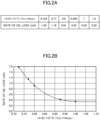
- a relationship under those conditions between a volume ratio represented by (A+B)*D 2 /(Vcc*Nmax) (a ratio between a spatial volume in the casing and the suction volume of the compressor (10) at the maximum number of rotations) and a rate of oil loss at a plurality of points where the volume ratio ranges from about 0.70 to 1.20 is shown in the table of FIG. 2A and the graph of FIG. 2B .
- a relationship under the same conditions between the volume ratio and a vibration amount (the amount of vibration of the casing (20)) at a plurality of points where the volume ratio ranges from about 0.70 to 1.10 is shown in the table of FIG. 3A and the graph of FIG. 3B .
- the rate of oil loss is a ratio between the total amount of oil and the amount of oil having flowed out of the casing (20).
- the volume ratio decreases, i.e., as the spatial volume in the casing (20) with respect to the suction volume at the maximum number of rotations decreases, the rate of oil loss increases and the amount of oil flowing out of the casing (20) increases.
- the volume ratio increases, i.e., as the spatial volume in the casing (20) with respect to the suction volume Vcc at the maximum number Nmax of rotations increases, the rate of oil loss decreases and the amount of oil flowing out of the casing (20) decreases.
- the volume ratio satisfies the relationship represented by 0.8 ⁇ (A+B)*D 2 /(Vcc*Nmax) ⁇ 1.0, and the rate of oil loss ranges between 0.91 to 0.35 as shown in FIGS. 2A and 2B . If the volume ratio is smaller than 0.8, the rate of oil loss is higher, but according to this embodiment, an increase in the rate of oil loss can be reduced. If the volume ratio is larger than 1.0, the rate of oil loss is substantially constant, and thus the spatial volume in the casing (20) does not need to be excessively large and upsizing of the casing (20) can be reduced.
- the volume ratio satisfies the relationship represented by 0.8 ⁇ (A+B)*D 2 /(Vcc*Nmax) ⁇ 1.0, and the vibration amount ( ⁇ m) of the casing (20) ranges from 27.5 to 30 ( ⁇ m) as shown in FIGS. 3A and 3B . If the volume ratio is smaller than 0.8, the vibration amount is smaller while the rate of oil loss is higher, but according to this embodiment, both the vibration amount and the rate of oil loss are reduced. Further, if the volume ratio is larger than 1.0, the vibration amount is larger, but according to this embodiment, the vibration amount can be reduced while the rate of oil loss is reduced.
- a conventional compressor has a barrel with a smaller diameter for downsizing and operates at a higher rotational speed to ensure an appropriate amount of discharge, an average gas flow velocity directing upward from a compression mechanism to a discharge pipe increases. Accordingly, the oil separation effect in a space in a casing decreases, and the amount of oil loss increases. If the spatial volume in the casing is made larger to deal with the problem, the compressor is upsized.
- the volume ratio is set to 0.8 ⁇ (A+B)*D 2 /(Vcc*Nmax) ⁇ 1.0.
- the range of the volume ratio is determined so that the vibration amount is reduced.
- the height of the casing (20) of the compressor (10) is reduced so that downsizing can be achieved, and also the height of the casing (20) is reduced so that even when the compressor (10) operates at a high speed, an increase in the rate of oil loss can be reduced while the vibration can be reduced.
- vibration of the compressor (10) is reduced, and thus damage to the casing (20) and the pipe due to the vibration can be reduced. Further, the rate of oil loss is reduced, and thus decrease in the reliability of the sliding portion of the compressor (10) can be reduced.
- the compressor (10) includes the casing (20) with a smaller diameter and operates at a high speed, where an increase in the rate of oil loss can be reduced while the vibration of the casing (20) can be reduced.
- the compressor has a small capacity, where an increase in the rate of oil loss can be reduced while the vibration of the casing (20) can be reduced.
- the rate of oil loss of the compressor (10) is reduced, thereby reducing lubricant oil adhering to the heat exchangers (2, 4) of the refrigerant circuit and inhibiting heat transfer.
- a decrease in the system efficiency can also be reduced.
- the volume ratio may be set to a range of 0.85 ⁇ (A+B)*D 2 /(Vcc*Nmax) ⁇ 0.95.
- the range of the volume ratio is limited to a range narrower than that of the above embodiment.
- the rate of oil loss can be further reduced than according to the above embodiment.
- upsizing of the casing (20) can be further reduced and the vibration amount can also be reduced.
- damage to the casing (20) and the pipe, a decrease in the reliability of the compressor (10), and a reduction in the system efficiency can be further reduced.
- the volume ratio may be set to a range of 0.9 ⁇ (A+B)*D ⁇ 2/(Vcc*Nmax) ⁇ 1.0.
- the rate of oil loss can be further reduced than according to the above embodiment and the first variation, and upsizing of the casing (20) can be reduced as easily as according to the embodiment and the first variation.
- the vibration amount can be reduced.
- a decrease in the reliability of the compressor (10) and a reduction in the system efficiency can be further reduced while damage to the casing (20) and the pipe can be reduced.
- the present disclosure is useful for a rotary type compressor and an air conditioner.
Landscapes
- Engineering & Computer Science (AREA)
- Mechanical Engineering (AREA)
- General Engineering & Computer Science (AREA)
- Physics & Mathematics (AREA)
- Thermal Sciences (AREA)
- Applications Or Details Of Rotary Compressors (AREA)
- Compressor (AREA)
Abstract
Description
- The present disclosure relates to a rotary type compressor and an air conditioner.
- In general, a rotary type compressor includes a cylindrical casing closed at both ends and housing an electric motor and a compression mechanism, where the compression mechanism is driven by the electric motor (see, e.g., Patent Document 1).
- The compressor of
Patent Document 1 uses a concentrated winding electric motor in order to reduce the size of a coil and to ensure a space for separating lubricant oil from a refrigerant in the casing. This compressor satisfies a relationship represented by 0.3 ≤ L1/(L1+L2) ≤ 0.6 between the height (L1) of a space in the casing above the electric motor and the height (L2) of the electric motor (the height from the upper end to the lower end of the coil), thereby reducing upsizing of the casing. - [Patent Document 1]
Japanese Patent No. 3670890 - However, in
Patent Document 1, when the compressor rotates at a high speed, the flow velocity of the refrigerant in the casing increases, and thus the lubricant oil is not sufficiently separated from the refrigerant and is discharged outside of the casing. As a result, the amount of oil discharged increases, which may lead to a decrease in the reliability of the compressor. - It is an object of the present disclosure to sufficiently separate lubricant oil from a refrigerant in a casing even when a compressor is rotated at a high speed.
- A first aspect of the present disclosure is directed to a rotary type compressor including: a cylindrical casing (20) having a first end plate (22) at one end in an axial direction and a second end plate (23) at another other end in the axial direction; an electric motor (40) that is a variable-speed type electric motor and that is disposed in the casing (20) in which a first space (S 1) is sandwiched between the electric motor (40) and the first end plate (22); and a compression mechanism (30) that is disposed in the casing (20) in which a second space (S2) is sandwiched between the compression mechanism (30) and the electric motor (40) and that is coupled with the electric motor (40), wherein the rotational compressor satisfies a relationship represented by 0.8 ≤ (A+B)*D2/(Vcc*Nmax) ≤ 1.0, where an axial length of the first space (S1) is A (mm), an axial length of the second space (S2) is B (mm), an inner diameter of the casing (20) is D (mm), a suction volume per rotation of the compression mechanism (30) is Vcc (mm3), and a maximum rotational speed of the compression mechanism (30) is Nmax (rps).
- According to the first aspect, the value of (A+B)*D2/(Vcc*Nmax), a ratio between the spatial volume in the casing (20) and the suction volume of the compressor at the maximum number of rotations, is defined as the above range. Thus, even when the compressor is operated at a high speed, lubricant oil can be sufficiently separated from a refrigerant in the casing (20).
- A second aspect of the present disclosure is an embodiment of the first aspect. In the rotary type compressor of the second aspect, the relationships of D < 100 and Nmax ≥ 118 are satisfied.
- According to the second aspect, particularly when the casing is downsized and the compressor is operated at a high speed, lubricant oil can be sufficiently separated from a refrigerant in the casing.
- A third aspect of the present disclosure is an embodiment of the first or second aspect. In the rotary type compressor of the third aspect, a relationship represented by 0.85 ≤ (A+B)*D2/(Vcc*Nmax) ≤ 0.95 is satisfied.
- According to the third aspect, the range of the volume ratio is defined as a narrower range than that of the first aspect, and thus, when the compressor is rotated at a high speed, lubricant oil can be more sufficiently separated from a refrigerant in the casing.
- A fourth aspect of the present disclosure is an embodiment of any one of the first to third aspects. In the rotary type compressor of the fourth aspect, a relationship represented by 6×10³ ≤ Vcc ≤ 8× 10³ is satisfied.
- A fifth aspect of the present disclosure is directed to an air conditioner including: a refrigerant circuit (1) of a vapor compression refrigeration cycle, wherein a compressor (10) of the refrigerant circuit (1) is the rotary type compressor of any one of the first to fourth aspects.
-
-
FIG. 1 is a sectional view of a rotary type compressor of an embodiment. -
FIG. 2A is a table showing a relationship between a volume ratio represented by (A+B)*D2/(Vcc*Nmax) (a ratio between the spatial volume in a casing and the suction volume of the compressor at the maximum number of rotations) and a rate of oil loss. -
FIG. 2B is a graph showing of the relationship between the volume ratio represented by (A+B)*D2/(Vcc*Nmax) and the rate of oil loss. -
FIG. 3A is a table showing a relationship between the volume ratio represented by (A+B)*D2/(Vcc*Nmax) and the value of vibration of the compressor. -
FIG. 3B is a graph showing the relationship between the volume ratio represented by (A+B)*D2/(Vcc*Nmax) and the value of vibration of the compressor. - An embodiment will be described below in detail with reference to the drawings.
- A rotary type compressor (hereinafter simply referred to as a compressor) (10) of this embodiment is an oscillating piston compressor (10), and is connected to a refrigerant circuit (1) as shown in
FIG. 1 . The refrigerant circuit (1) includes the compressor (10), a radiator (2), an expansion mechanism (3), and an evaporator (4) connected in sequence via a refrigerant pipe (5), and performs a vapor compression refrigeration cycle by a refrigerant circulating therein. In general, as the expansion mechanism (3), an expansion valve whose opening degree is adjustable is used, but another component such as a capillary tube whose opening degree is fixed may be used. - The compressor (10) includes a casing (20). The casing (20) is a closed container having a vertically long cylindrical shape and including a first end plate (22) at one end (upper end) and a second end plate (23) at the other end (lower end) of a cylindrical barrel (21) in the axial direction. The casing (20) houses a compression mechanism (30) that compresses a refrigerant in the refrigerant circuit (1) and an electric motor (40) that is a variable-speed type electric motor and that drives the compression mechanism (30), where compression mechanism (30) and the electric motor (40) are fixed to the inner peripheral surface of the barrel (21). The electric motor (40) is disposed in the casing (20) in which a first space (S1) is sandwiched between the electric motor (40) and the first end plate (22), and the compression mechanism (30) is disposed in the casing (20) in which a second space (S2) is sandwiched between the compression mechanism (30) and the electric motor (40).
- The electric motor (40) includes a stator (41) and a rotor (42), both formed in a cylindrical shape. The stator (41) is fixed to the barrel (21) of the casing (20). The stator (41) includes a hollow portion where the rotor (42) is disposed. A drive shaft (45) is fixed to a hollow portion of the rotor (42) so as to penetrate the rotor (42), and that the rotor (42) and the drive shaft (45) rotates integrally.
- The drive shaft (45) includes a main shaft portion (46) extending vertically. The drive shaft (45) is formed integrally with an eccentric portion (47) near a lower end of the main shaft portion (46). The eccentric portion (47) has a larger diameter than the main shaft portion (46). The eccentric portion (47) has an axis decentered by a predetermined distance with respect to the axis of the main shaft portion (46).
- A lower end portion of the main shaft portion (46) is provided with an oil supply pump (48). The oil supply pump (48) is immersed in lubricant oil in an oil reservoir formed at the bottom of the casing (20). The oil supply pump (48) pumps up lubricant oil into an oil supply path (not shown) in the drive shaft (45) along with rotation of the drive shaft (45), and then supplies the lubricant oil to each sliding portion of the compression mechanism (30).
- The compression mechanism (30) includes a cylinder (31) formed in an annular shape. The cylinder (31) has one axial end (upper end) to which a front head (32) is fixed and the other axial end (lower end) to which a rear head (33) is fixed. The cylinder (31), the front head (32), and the rear head (33) are stacked from top to bottom in order of the front head (32), the cylinder (31), and the rear head (33), and are fastened and fixed together with a plurality of bolts, for example.
- The drive shaft (45) vertically penetrates the compression mechanism (30). The front head (32) and the rear head (33) are provided with bearing portions (32a, 33a) that support the drive shaft (45) at both above and below the eccentric portion (47).
- The cylinder (31) has an upper end closed by the front head (32) and a lower end closed by the rear head (33). The internal space of the cylinder (31) forms a cylinder chamber (35). The cylinder (31) (cylinder chamber (35)) houses a tubular piston (34) slidably fitted to the eccentric portion (47) of the drive shaft (45). As the drive shaft (45) rotates, the piston (34) rotates eccentrically in the cylinder chamber (35). Although not shown in the figure, the piston (34) has an outer peripheral surface integrated with a blade extending radially outward from the outer peripheral surface of the piston (34). The blade is held by a bush (not shown) provided in the piston (34) and swings along with rotation of the drive shaft (45). Thus, the piston (34) being rotated by itself is restricted.
- The cylinder (31) has a suction port (31a) communicating with the cylinder chamber (35). The suction port (31a) is connected with a suction pipe (36) fixed to the barrel (21). The suction pipe (36) is connected with an accumulator (37) fixed to the casing (20).
- The front head (32) has a discharge port (32b) extending parallel to the axis of the drive shaft (45). The discharge port (32b) is opened and closed by a discharge valve (not shown). A muffler (38) is attached to an upper surface of the front head (32) so as to cover the discharge port (32b) and the discharge valve. A muffler space (38a) defined in the muffler (38) communicates with the internal space of the casing (20) through a discharge opening (38b) formed on an upper portion of the muffler (38).
- As described above, the suction pipe (36) connected to the suction port (31a) is attached to the casing (20) so that a refrigerant is sucked into the compression mechanism (30) through the accumulator (37) and the suction pipe (36).
- A discharge pipe (39) is attached to the casing (20) and penetrates the first end plate (22). A lower end portion of the discharge pipe (39) is open to the inside of the casing (20). The discharge port (32b) of the compression mechanism (30) communicates with the internal space of the casing (20) through the discharge opening (38b) of the muffler (38). A refrigerant discharged from the compression mechanism (30) flows out of the casing (20) through the internal space of the casing (20) and the discharge pipe (39).
- The first end plate (22) of the casing (20) is provided with a terminal (50) to which an electric wire for supplying electric power to the electric motor (40) is connected.
- The compressor of this embodiment satisfies a relationship represented by 0.8 ≤ (A+B)*D2/(Vcc*Nmax) ≤ 1.0, where the axial length of the first space (S1) is A (mm), the axial length of the second space (S2) is B (mm), the inner diameter of the casing (20) is D (mm), the suction volume per rotation of the compression mechanism (30) is Vcc (mm3), and the maximum rotational speed of the compression mechanism (30) is Nmax (rps).
- According to this embodiment, D < 100, Nmax ≥ 118, and 6×10³ ≤ Vcc ≤ 8×10³. The values A and B are determined as appropriate (for example, the value A may be about 50 to 70 mm, and the value B may be about 20 to 30 mm).
- A relationship under those conditions between a volume ratio represented by (A+B)*D2/(Vcc*Nmax) (a ratio between a spatial volume in the casing and the suction volume of the compressor (10) at the maximum number of rotations) and a rate of oil loss at a plurality of points where the volume ratio ranges from about 0.70 to 1.20 is shown in the table of
FIG. 2A and the graph ofFIG. 2B . Further, a relationship under the same conditions between the volume ratio and a vibration amount (the amount of vibration of the casing (20)) at a plurality of points where the volume ratio ranges from about 0.70 to 1.10 is shown in the table ofFIG. 3A and the graph ofFIG. 3B . - The rate of oil loss is a ratio between the total amount of oil and the amount of oil having flowed out of the casing (20). As the volume ratio decreases, i.e., as the spatial volume in the casing (20) with respect to the suction volume at the maximum number of rotations decreases, the rate of oil loss increases and the amount of oil flowing out of the casing (20) increases. As the volume ratio increases, i.e., as the spatial volume in the casing (20) with respect to the suction volume Vcc at the maximum number Nmax of rotations increases, the rate of oil loss decreases and the amount of oil flowing out of the casing (20) decreases.
- According to this embodiment, the volume ratio satisfies the relationship represented by 0.8 ≤ (A+B)*D2/(Vcc*Nmax) ≤ 1.0, and the rate of oil loss ranges between 0.91 to 0.35 as shown in
FIGS. 2A and 2B . If the volume ratio is smaller than 0.8, the rate of oil loss is higher, but according to this embodiment, an increase in the rate of oil loss can be reduced. If the volume ratio is larger than 1.0, the rate of oil loss is substantially constant, and thus the spatial volume in the casing (20) does not need to be excessively large and upsizing of the casing (20) can be reduced. - The volume ratio satisfies the relationship represented by 0.8 ≤ (A+B)*D2/(Vcc*Nmax) ≤ 1.0, and the vibration amount (µm) of the casing (20) ranges from 27.5 to 30 (µm) as shown in
FIGS. 3A and 3B . If the volume ratio is smaller than 0.8, the vibration amount is smaller while the rate of oil loss is higher, but according to this embodiment, both the vibration amount and the rate of oil loss are reduced. Further, if the volume ratio is larger than 1.0, the vibration amount is larger, but according to this embodiment, the vibration amount can be reduced while the rate of oil loss is reduced. - If a conventional compressor has a barrel with a smaller diameter for downsizing and operates at a higher rotational speed to ensure an appropriate amount of discharge, an average gas flow velocity directing upward from a compression mechanism to a discharge pipe increases. Accordingly, the oil separation effect in a space in a casing decreases, and the amount of oil loss increases. If the spatial volume in the casing is made larger to deal with the problem, the compressor is upsized.
- According to this embodiment, the volume ratio is set to 0.8 ≤ (A+B)*D2/(Vcc*Nmax) ≤ 1.0. As described above, according to this embodiment, not only the spatial volume in the casing (20) is increased so that the rate of oil loss is reduced, but also the range of the volume ratio is determined so that the vibration amount is reduced. In particular, the height of the casing (20) of the compressor (10) is reduced so that downsizing can be achieved, and also the height of the casing (20) is reduced so that even when the compressor (10) operates at a high speed, an increase in the rate of oil loss can be reduced while the vibration can be reduced.
- According to this embodiment, vibration of the compressor (10) is reduced, and thus damage to the casing (20) and the pipe due to the vibration can be reduced. Further, the rate of oil loss is reduced, and thus decrease in the reliability of the sliding portion of the compressor (10) can be reduced.
- According to this embodiment, the relationships represented by D < 100 and Nmax ≥ 118 are satisfied. According to this embodiment, the compressor (10) includes the casing (20) with a smaller diameter and operates at a high speed, where an increase in the rate of oil loss can be reduced while the vibration of the casing (20) can be reduced.
- According to this embodiment, the relationship represented by 6×10³ ≤ Vcc ≤ 8×10³ is satisfied. According to this embodiment, the compressor has a small capacity, where an increase in the rate of oil loss can be reduced while the vibration of the casing (20) can be reduced.
- According to an air conditioner including the compressor of this embodiment, the rate of oil loss of the compressor (10) is reduced, thereby reducing lubricant oil adhering to the heat exchangers (2, 4) of the refrigerant circuit and inhibiting heat transfer. Thus, a decrease in the system efficiency can also be reduced.
- The above embodiment may be modified as follows.
- In the above embodiment, the volume ratio may be set to a range of 0.85 ≤ (A+B)*D2/(Vcc*Nmax) ≤ 0.95.
- Accordingly, the range of the volume ratio is limited to a range narrower than that of the above embodiment. Thus, the rate of oil loss can be further reduced than according to the above embodiment. Then, upsizing of the casing (20) can be further reduced and the vibration amount can also be reduced. As a result, damage to the casing (20) and the pipe, a decrease in the reliability of the compressor (10), and a reduction in the system efficiency can be further reduced.
- In the above embodiment, the volume ratio may be set to a range of 0.9 ≤ (A+B)*
D ^2/(Vcc*Nmax) ≤ 1.0. - Accordingly, the rate of oil loss can be further reduced than according to the above embodiment and the first variation, and upsizing of the casing (20) can be reduced as easily as according to the embodiment and the first variation. Thus, the vibration amount can be reduced. As a result, a decrease in the reliability of the compressor (10) and a reduction in the system efficiency can be further reduced while damage to the casing (20) and the pipe can be reduced.
- While the embodiment and variations thereof have been described above, it will be understood that various changes in form and details may be made without departing from the spirit and scope of the claims. The elements according to the embodiments, the variations thereof, and the other embodiments may be combined and replaced with each other.
- As described above, the present disclosure is useful for a rotary type compressor and an air conditioner.
-
- 1
- Refrigerant Circuit
- 10
- Rotary Type Compressor
- 20
- Casing
- 22
- First End Plate
- 23
- Second End Plate
- 30
- Compression Mechanism
- 40
- Electric Motor
- S1
- First Space
- S2
- Second Space
Claims (5)
- A rotary type compressor comprising:a cylindrical casing (20) having a first end plate (22) at one end in an axial direction and a second end plate (23) at another other end in the axial direction;an electric motor (40) that is a variable-speed type electric motor and that is disposed in the casing (20) in which a first space (S 1) is sandwiched between the electric motor (40) and the first end plate (22); anda compression mechanism (30) that is disposed in the casing (20) in which a second space (S2) is sandwiched between the compression mechanism (30) and the electric motor (40) and that is coupled with the electric motor (40),whereinthe rotational compressor satisfies a relationship represented by 0.8 ≤ (A+B)*D2/(Vcc*Nmax) ≤ 1.0, where an axial length of the first space (S1) is A (mm), an axial length of the second space (S2) is B (mm), an inner diameter of the casing (20) is D (mm), a suction volume per rotation of the compression mechanism (30) is Vcc (mm3), and a maximum rotational speed of the compression mechanism (30) is Nmax (rps).
- The rotary type compressor of claim 1, wherein

- The rotary type compressor of claim 1 or 2, wherein

- The rotary type compressor of any one of claims 1 to 3, wherein

- An air conditioner comprising:a refrigerant circuit (1) of a vapor compression refrigeration cycle,whereina compressor (10) of the refrigerant circuit (1) is the rotary type compressor of any one of claims 1 to 4.
Applications Claiming Priority (2)
| Application Number | Priority Date | Filing Date | Title |
|---|---|---|---|
| JP2022048468A JP7284436B1 (en) | 2022-03-24 | 2022-03-24 | rotary compressor and air conditioner |
| PCT/JP2023/005009 WO2023181712A1 (en) | 2022-03-24 | 2023-02-14 | Rotary compressor and air conditioner |
Publications (3)
| Publication Number | Publication Date |
|---|---|
| EP4455484A1 true EP4455484A1 (en) | 2024-10-30 |
| EP4455484A4 EP4455484A4 (en) | 2025-04-23 |
| EP4455484B1 EP4455484B1 (en) | 2025-12-03 |
Family
ID=86538317
Family Applications (1)
| Application Number | Title | Priority Date | Filing Date |
|---|---|---|---|
| EP23774311.7A Active EP4455484B1 (en) | 2022-03-24 | 2023-02-14 | Rotary compressor and air conditioner |
Country Status (7)
| Country | Link |
|---|---|
| US (1) | US12292044B2 (en) |
| EP (1) | EP4455484B1 (en) |
| JP (1) | JP7284436B1 (en) |
| CN (1) | CN118541547B (en) |
| AU (1) | AU2023237934B2 (en) |
| ES (1) | ES3058567T3 (en) |
| WO (1) | WO2023181712A1 (en) |
Family Cites Families (12)
| Publication number | Priority date | Publication date | Assignee | Title |
|---|---|---|---|---|
| US6075304A (en) * | 1997-04-30 | 2000-06-13 | Alon Co., Ltd | Stator with molded encasement for small motors and manufacturing process therefor |
| US6102677A (en) * | 1997-10-21 | 2000-08-15 | Matsushita Electric Industrial Co., Ltd. | Hermetic compressor |
| TW564285B (en) * | 1999-06-29 | 2003-12-01 | Sanyo Electric Co | Sealed rotary compressor |
| JP3670890B2 (en) * | 1999-06-29 | 2005-07-13 | 三洋電機株式会社 | Hermetic rotary compressor |
| KR101234824B1 (en) * | 2005-01-18 | 2013-02-20 | 삼성전자주식회사 | Multi-stage compression type rotary compressor |
| JP5286937B2 (en) * | 2008-05-27 | 2013-09-11 | 株式会社富士通ゼネラル | Rotary compressor |
| JP5468215B2 (en) * | 2008-06-09 | 2014-04-09 | ダイキン工業株式会社 | Air conditioner and method of manufacturing air conditioner |
| JP6349623B2 (en) * | 2012-03-30 | 2018-07-04 | ダイキン工業株式会社 | Compressor |
| DE202017104967U1 (en) * | 2016-08-22 | 2017-11-29 | Trane International Inc. | Compressor noise reduction |
| CN206221247U (en) | 2016-09-23 | 2017-06-06 | 广东美芝制冷设备有限公司 | Rotary compressor and the air-conditioning system with it |
| KR20210002281A (en) * | 2019-06-28 | 2021-01-07 | 엘지전자 주식회사 | A Laundry Treatment Apparatus |
| CN110925200B (en) | 2019-12-11 | 2021-09-03 | 安徽美芝精密制造有限公司 | Single-cylinder compressor and refrigerating and heating equipment |
-
2022
- 2022-03-24 JP JP2022048468A patent/JP7284436B1/en active Active
-
2023
- 2023-02-14 WO PCT/JP2023/005009 patent/WO2023181712A1/en not_active Ceased
- 2023-02-14 CN CN202380017106.XA patent/CN118541547B/en active Active
- 2023-02-14 EP EP23774311.7A patent/EP4455484B1/en active Active
- 2023-02-14 AU AU2023237934A patent/AU2023237934B2/en active Active
- 2023-02-14 ES ES23774311T patent/ES3058567T3/en active Active
-
2024
- 2024-08-21 US US18/811,274 patent/US12292044B2/en active Active
Also Published As
| Publication number | Publication date |
|---|---|
| US12292044B2 (en) | 2025-05-06 |
| CN118541547A (en) | 2024-08-23 |
| US20240410349A1 (en) | 2024-12-12 |
| EP4455484B1 (en) | 2025-12-03 |
| JP7284436B1 (en) | 2023-05-31 |
| CN118541547B (en) | 2025-01-10 |
| AU2023237934B2 (en) | 2025-10-09 |
| EP4455484A4 (en) | 2025-04-23 |
| AU2023237934A1 (en) | 2024-11-07 |
| WO2023181712A1 (en) | 2023-09-28 |
| JP2023141896A (en) | 2023-10-05 |
| ES3058567T3 (en) | 2026-03-11 |
Similar Documents
| Publication | Publication Date | Title |
|---|---|---|
| US10890186B2 (en) | Compressor | |
| US10227983B2 (en) | Scroll compressor having an oil separation space | |
| CN105899808A (en) | Rotary compressor | |
| US8864480B2 (en) | Oil recovery member, and motor mechanism and compressor using the same | |
| US8118568B2 (en) | Hermetic compressor | |
| EP3540221B1 (en) | Compressor | |
| KR20180107482A (en) | Scroll compressor | |
| EP3636929B1 (en) | Rotary compressor | |
| EP4455484B1 (en) | Rotary compressor and air conditioner | |
| KR20180090324A (en) | Rotary compressor | |
| EP4455485A1 (en) | Compressor and air conditioner | |
| JP2003269335A (en) | Rotary compressor | |
| JP4992496B2 (en) | Rotary compressor | |
| KR101406509B1 (en) | An oil recovery member and a transmission mechanism and a compressor using the oil recovery member | |
| CN116075637B (en) | compressor | |
| JP2017101557A (en) | Hermetic type compressor | |
| KR101406521B1 (en) | Transmission mechanism and compressor using it | |
| JP2001289171A (en) | Refrigerant compressor | |
| JP2017096116A (en) | Compressor |
Legal Events
| Date | Code | Title | Description |
|---|---|---|---|
| STAA | Information on the status of an ep patent application or granted ep patent |
Free format text: STATUS: THE INTERNATIONAL PUBLICATION HAS BEEN MADE |
|
| PUAI | Public reference made under article 153(3) epc to a published international application that has entered the european phase |
Free format text: ORIGINAL CODE: 0009012 |
|
| STAA | Information on the status of an ep patent application or granted ep patent |
Free format text: STATUS: REQUEST FOR EXAMINATION WAS MADE |
|
| 17P | Request for examination filed |
Effective date: 20240723 |
|
| AK | Designated contracting states |
Kind code of ref document: A1 Designated state(s): AL AT BE BG CH CY CZ DE DK EE ES FI FR GB GR HR HU IE IS IT LI LT LU LV MC ME MK MT NL NO PL PT RO RS SE SI SK SM TR |
|
| P01 | Opt-out of the competence of the unified patent court (upc) registered |
Free format text: CASE NUMBER: APP_932/2025 Effective date: 20250108 |
|
| A4 | Supplementary search report drawn up and despatched |
Effective date: 20250324 |
|
| RIC1 | Information provided on ipc code assigned before grant |
Ipc: F04C 29/00 20060101ALI20250318BHEP Ipc: F04B 39/12 20060101ALI20250318BHEP Ipc: F04B 39/04 20060101ALI20250318BHEP Ipc: F04C 29/02 20060101AFI20250318BHEP |
|
| DAV | Request for validation of the european patent (deleted) | ||
| DAX | Request for extension of the european patent (deleted) | ||
| GRAP | Despatch of communication of intention to grant a patent |
Free format text: ORIGINAL CODE: EPIDOSNIGR1 |
|
| STAA | Information on the status of an ep patent application or granted ep patent |
Free format text: STATUS: GRANT OF PATENT IS INTENDED |
|
| INTG | Intention to grant announced |
Effective date: 20250723 |
|
| GRAS | Grant fee paid |
Free format text: ORIGINAL CODE: EPIDOSNIGR3 |
|
| GRAA | (expected) grant |
Free format text: ORIGINAL CODE: 0009210 |
|
| STAA | Information on the status of an ep patent application or granted ep patent |
Free format text: STATUS: THE PATENT HAS BEEN GRANTED |
|
| AK | Designated contracting states |
Kind code of ref document: B1 Designated state(s): AL AT BE BG CH CY CZ DE DK EE ES FI FR GB GR HR HU IE IS IT LI LT LU LV MC ME MK MT NL NO PL PT RO RS SE SI SK SM TR |
|
| REG | Reference to a national code |
Ref country code: CH Ref legal event code: F10 Free format text: ST27 STATUS EVENT CODE: U-0-0-F10-F00 (AS PROVIDED BY THE NATIONAL OFFICE) Effective date: 20251203 Ref country code: GB Ref legal event code: FG4D |
|
| REG | Reference to a national code |
Ref country code: DE Ref legal event code: R096 Ref document number: 602023009369 Country of ref document: DE |
|
| REG | Reference to a national code |
Ref country code: IE Ref legal event code: FG4D |
|
| REG | Reference to a national code |
Ref country code: ES Ref legal event code: FG2A Ref document number: 3058567 Country of ref document: ES Kind code of ref document: T3 Effective date: 20260311 |
|
| REG | Reference to a national code |
Ref country code: NL Ref legal event code: MP Effective date: 20251203 |
|
| REG | Reference to a national code |
Ref country code: LT Ref legal event code: MG9D |
|
| PG25 | Lapsed in a contracting state [announced via postgrant information from national office to epo] |
Ref country code: NO Free format text: LAPSE BECAUSE OF FAILURE TO SUBMIT A TRANSLATION OF THE DESCRIPTION OR TO PAY THE FEE WITHIN THE PRESCRIBED TIME-LIMIT Effective date: 20260303 |
|
| PGFP | Annual fee paid to national office [announced via postgrant information from national office to epo] |
Ref country code: DE Payment date: 20260218 Year of fee payment: 4 |
|
| PG25 | Lapsed in a contracting state [announced via postgrant information from national office to epo] |
Ref country code: FI Free format text: LAPSE BECAUSE OF FAILURE TO SUBMIT A TRANSLATION OF THE DESCRIPTION OR TO PAY THE FEE WITHIN THE PRESCRIBED TIME-LIMIT Effective date: 20251203 Ref country code: HR Free format text: LAPSE BECAUSE OF FAILURE TO SUBMIT A TRANSLATION OF THE DESCRIPTION OR TO PAY THE FEE WITHIN THE PRESCRIBED TIME-LIMIT Effective date: 20251203 |
|
| PGFP | Annual fee paid to national office [announced via postgrant information from national office to epo] |
Ref country code: AT Payment date: 20260301 Year of fee payment: 4 |
|
| PGFP | Annual fee paid to national office [announced via postgrant information from national office to epo] |
Ref country code: IT Payment date: 20260228 Year of fee payment: 4 |
|
| PG25 | Lapsed in a contracting state [announced via postgrant information from national office to epo] |
Ref country code: RS Free format text: LAPSE BECAUSE OF FAILURE TO SUBMIT A TRANSLATION OF THE DESCRIPTION OR TO PAY THE FEE WITHIN THE PRESCRIBED TIME-LIMIT Effective date: 20260303 |
|
| PGFP | Annual fee paid to national office [announced via postgrant information from national office to epo] |
Ref country code: FR Payment date: 20260219 Year of fee payment: 4 |
|
| PG25 | Lapsed in a contracting state [announced via postgrant information from national office to epo] |
Ref country code: PL Free format text: LAPSE BECAUSE OF FAILURE TO SUBMIT A TRANSLATION OF THE DESCRIPTION OR TO PAY THE FEE WITHIN THE PRESCRIBED TIME-LIMIT Effective date: 20251203 |
|
| PG25 | Lapsed in a contracting state [announced via postgrant information from national office to epo] |
Ref country code: LV Free format text: LAPSE BECAUSE OF FAILURE TO SUBMIT A TRANSLATION OF THE DESCRIPTION OR TO PAY THE FEE WITHIN THE PRESCRIBED TIME-LIMIT Effective date: 20251203 |
|
| PG25 | Lapsed in a contracting state [announced via postgrant information from national office to epo] |
Ref country code: BG Free format text: LAPSE BECAUSE OF FAILURE TO SUBMIT A TRANSLATION OF THE DESCRIPTION OR TO PAY THE FEE WITHIN THE PRESCRIBED TIME-LIMIT Effective date: 20251203 |
|
| REG | Reference to a national code |
Ref country code: AT Ref legal event code: MK05 Ref document number: 1863869 Country of ref document: AT Kind code of ref document: T Effective date: 20251203 |
|
| PG25 | Lapsed in a contracting state [announced via postgrant information from national office to epo] |
Ref country code: NL Free format text: LAPSE BECAUSE OF FAILURE TO SUBMIT A TRANSLATION OF THE DESCRIPTION OR TO PAY THE FEE WITHIN THE PRESCRIBED TIME-LIMIT Effective date: 20251203 |
|
| PG25 | Lapsed in a contracting state [announced via postgrant information from national office to epo] |
Ref country code: LT Free format text: LAPSE BECAUSE OF FAILURE TO SUBMIT A TRANSLATION OF THE DESCRIPTION OR TO PAY THE FEE WITHIN THE PRESCRIBED TIME-LIMIT Effective date: 20251203 |
|
| PG25 | Lapsed in a contracting state [announced via postgrant information from national office to epo] |
Ref country code: SM Free format text: LAPSE BECAUSE OF FAILURE TO SUBMIT A TRANSLATION OF THE DESCRIPTION OR TO PAY THE FEE WITHIN THE PRESCRIBED TIME-LIMIT Effective date: 20251203 |
|
| PGFP | Annual fee paid to national office [announced via postgrant information from national office to epo] |
Ref country code: ES Payment date: 20260424 Year of fee payment: 4 |
|
| PG25 | Lapsed in a contracting state [announced via postgrant information from national office to epo] |
Ref country code: AT Free format text: LAPSE BECAUSE OF FAILURE TO SUBMIT A TRANSLATION OF THE DESCRIPTION OR TO PAY THE FEE WITHIN THE PRESCRIBED TIME-LIMIT Effective date: 20251203 |
|
| PG25 | Lapsed in a contracting state [announced via postgrant information from national office to epo] |
Ref country code: EE Free format text: LAPSE BECAUSE OF FAILURE TO SUBMIT A TRANSLATION OF THE DESCRIPTION OR TO PAY THE FEE WITHIN THE PRESCRIBED TIME-LIMIT Effective date: 20251203 |
|
| PG25 | Lapsed in a contracting state [announced via postgrant information from national office to epo] |
Ref country code: PT Free format text: LAPSE BECAUSE OF FAILURE TO SUBMIT A TRANSLATION OF THE DESCRIPTION OR TO PAY THE FEE WITHIN THE PRESCRIBED TIME-LIMIT Effective date: 20260406 Ref country code: IS Free format text: LAPSE BECAUSE OF FAILURE TO SUBMIT A TRANSLATION OF THE DESCRIPTION OR TO PAY THE FEE WITHIN THE PRESCRIBED TIME-LIMIT Effective date: 20260403 |
|
| PG25 | Lapsed in a contracting state [announced via postgrant information from national office to epo] |
Ref country code: CZ Free format text: LAPSE BECAUSE OF FAILURE TO SUBMIT A TRANSLATION OF THE DESCRIPTION OR TO PAY THE FEE WITHIN THE PRESCRIBED TIME-LIMIT Effective date: 20251203 |
|
| PG25 | Lapsed in a contracting state [announced via postgrant information from national office to epo] |
Ref country code: SK Free format text: LAPSE BECAUSE OF FAILURE TO SUBMIT A TRANSLATION OF THE DESCRIPTION OR TO PAY THE FEE WITHIN THE PRESCRIBED TIME-LIMIT Effective date: 20251203 |
|
| PG25 | Lapsed in a contracting state [announced via postgrant information from national office to epo] |
Ref country code: SE Free format text: LAPSE BECAUSE OF FAILURE TO SUBMIT A TRANSLATION OF THE DESCRIPTION OR TO PAY THE FEE WITHIN THE PRESCRIBED TIME-LIMIT Effective date: 20251203 |