EP4455469A2 - Flugzeugtriebwerksteuerungssystem zur aufrechterhaltung eines konstanten schubs unter dem meeresspiegel - Google Patents
Flugzeugtriebwerksteuerungssystem zur aufrechterhaltung eines konstanten schubs unter dem meeresspiegel Download PDFInfo
- Publication number
- EP4455469A2 EP4455469A2 EP24172836.9A EP24172836A EP4455469A2 EP 4455469 A2 EP4455469 A2 EP 4455469A2 EP 24172836 A EP24172836 A EP 24172836A EP 4455469 A2 EP4455469 A2 EP 4455469A2
- Authority
- EP
- European Patent Office
- Prior art keywords
- thrust
- engine
- current
- prescribed
- sea level
- Prior art date
- Legal status (The legal status is an assumption and is not a legal conclusion. Google has not performed a legal analysis and makes no representation as to the accuracy of the status listed.)
- Pending
Links
Images
Classifications
-
- F—MECHANICAL ENGINEERING; LIGHTING; HEATING; WEAPONS; BLASTING
- F02—COMBUSTION ENGINES; HOT-GAS OR COMBUSTION-PRODUCT ENGINE PLANTS
- F02C—GAS-TURBINE PLANTS; AIR INTAKES FOR JET-PROPULSION PLANTS; CONTROLLING FUEL SUPPLY IN AIR-BREATHING JET-PROPULSION PLANTS
- F02C9/00—Controlling gas-turbine plants; Controlling fuel supply in air- breathing jet-propulsion plants
- F02C9/26—Control of fuel supply
- F02C9/28—Regulating systems responsive to plant or ambient parameters, e.g. temperature, pressure, rotor speed
-
- B—PERFORMING OPERATIONS; TRANSPORTING
- B64—AIRCRAFT; AVIATION; COSMONAUTICS
- B64D—EQUIPMENT FOR FITTING IN OR TO AIRCRAFT; FLIGHT SUITS; PARACHUTES; ARRANGEMENT OR MOUNTING OF POWER PLANTS OR PROPULSION TRANSMISSIONS IN AIRCRAFT
- B64D31/00—Power plant control systems; Arrangement of power plant control systems in aircraft
- B64D31/02—Initiating means
- B64D31/06—Initiating means actuated automatically
-
- F—MECHANICAL ENGINEERING; LIGHTING; HEATING; WEAPONS; BLASTING
- F05—INDEXING SCHEMES RELATING TO ENGINES OR PUMPS IN VARIOUS SUBCLASSES OF CLASSES F01-F04
- F05D—INDEXING SCHEME FOR ASPECTS RELATING TO NON-POSITIVE-DISPLACEMENT MACHINES OR ENGINES, GAS-TURBINES OR JET-PROPULSION PLANTS
- F05D2270/00—Control
- F05D2270/01—Purpose of the control system
- F05D2270/12—Purpose of the control system to maintain desired vehicle trajectory parameters
-
- F—MECHANICAL ENGINEERING; LIGHTING; HEATING; WEAPONS; BLASTING
- F05—INDEXING SCHEMES RELATING TO ENGINES OR PUMPS IN VARIOUS SUBCLASSES OF CLASSES F01-F04
- F05D—INDEXING SCHEME FOR ASPECTS RELATING TO NON-POSITIVE-DISPLACEMENT MACHINES OR ENGINES, GAS-TURBINES OR JET-PROPULSION PLANTS
- F05D2270/00—Control
- F05D2270/70—Type of control algorithm
- F05D2270/71—Type of control algorithm synthesized, i.e. parameter computed by a mathematical model
Definitions
- the present disclosure relates generally to an aircraft engine control system and more specifically to an aircraft engine control system for tailoring engine thrust to a selected aircraft operating parameter.
- An aircraft engine generates a controlled amount of thrust during flight.
- the amount of thrust generated by an engine is partially determined by ambient conditions and therefore a controller uses information indicative of the ambient conditions to control engine operation and thereby thrust.
- Thrust generated by the engine may not be directly measurable during aircraft operation and therefore measurable engine operating parameters are monitored and controlled to set a desired thrust.
- Such engine operating parameters can include, for example, shaft or rotor speed, engine temperature and engine pressure. The engine is then operated to provide a specific shaft speed, rotor speed, temperature, or pressure to set a desired thrust.
- a method of controlling an aircraft engine with an engine control system to set a prescribed thrust at a selected aircraft operating parameter independent of a thrust setting model that determines thrust based on a current aircraft operating parameter includes, among other possible things, determining a reference thrust that corresponds to a thrust setting parameter at the selected aircraft operating parameter for a current airspeed according to a predefined relationship, calculating an adjustment factor based on a relationship between the current aircraft operating parameter and the selected aircraft operating parameter, determining the prescribed thrust at the current aircraft operating parameter by applying the adjustment factor to the reference thrust, determining a value of the thrust setting parameter that provides the prescribed thrust at the current aircraft operating parameter according to a predefined relationship between the reference thrust and the current airspeed, and operating the aircraft engine based on the determined value of the thrust setting parameter to provide the prescribed thrust.
- the selected aircraft operating parameter comprises a sea level altitude and the current aircraft operating parameter comprises the current altitude.
- the thrust setting model is configured for determining a thrust based on the current altitude for altitudes above sea level and the prescribed thrust is determined independent of the thrust setting model to provide a constant thrust for operation at altitudes below sea level.
- the method further comprises determining the thrust based on the thrust setting model in response to the aircraft operating at an altitude above sea level.
- determining the reference thrust corresponding to the thrust setting parameter for a current airspeed according to the predefined relationship comprises looking up the reference thrust that corresponds to the current air speed, and the thrust setting parameter in a look-up table.
- determining the thrust setting parameter value that corresponds with the prescribed thrust at the current airspeed comprises looking up the thrust setting parameter value that corresponds with the prescribed thrust at the current airspeed in a look-up table.
- the thrust setting parameter comprises a rotational speed of an engine shaft.
- the thrust setting parameter comprises at least one of a measured engine operating temperature and a measured engine operating pressure.
- calculating the adjustment factor is based on a measured ambient pressure at the current altitude and a determined ambient pressure at sea level.
- a method of controlling an aircraft engine with an engine control system to maintain a prescribed engine thrust at a value that corresponds to operation at sea level independent of a current altitude of an aircraft includes, among other possible things, determining a reference thrust that corresponds to a value of a thrust setting parameter at sea level for a current air speed according to a predefined relationship in response to operation below sea level, calculating an adjustment factor based on a relationship between a current altitude and sea level, determining the prescribed engine thrust at the current altitude by applying the adjustment factor to the reference thrust, determining the value of the thrust setting parameter that provides the prescribed engine thrust at sea level according to a predefined relationship of the reference thrust and the current airspeed, and operating the engine based on the determined value of the thrust setting parameter to provide the prescribed engine thrust.
- determining the reference thrust corresponding to the value of the thrust setting parameter at sea level according to the predefined relationship comprises looking up the reference thrust that corresponds to the current airspeed and the value of the thrust setting parameter in a look-up table.
- determining the value of the thrust setting parameter that provides the prescribed engine thrust at sea level according to the predefined relationship comprises looking up the value of the thrust setting parameter that corresponds to the prescribed thrust and the current airspeed in a look-up table.
- the thrust setting parameter comprises a rotational speed of an engine shaft.
- the thrust setting parameter comprises at least one of a measured engine operating temperature and a measured engine operating pressure.
- calculating the adjustment factor is at least partially based on a measured ambient pressure at the current altitude and a determined ambient pressure at sea level.
- a control system for an aircraft engine includes, among other possible things, a controller that includes a processor and a memory for storing engine operating settings that are indicative of a prescribed thrust based on a thrust setting parameter and an aircraft operating condition.
- the controller is programmed to receive information indicative of the thrust setting parameter and the aircraft operating condition from at least one sensor that is associated with an aircraft engine, to set the prescribed thrust at a selected aircraft operating parameter independent of a thrust setting model by determining a reference thrust that corresponds to a value of the thrust setting parameter at the selected aircraft operating parameter for a current aircraft operating parameter according to a predefined relationship in response to operation at a threshold aircraft operating condition, to calculate an adjustment factor based on a difference between a current aircraft operating parameter and the selected aircraft operating parameter, to determine the prescribed thrust at the current aircraft operating parameter by applying the adjustment factor to the reference thrust, and to determine a value of the thrust setting parameter that provides the prescribed thrust at the current aircraft operating parameter according to a predefined relationship of the reference thrust and a current airspeed.
- the controller is further programmed to operate the aircraft engine based on the determined value of the thrust setting parameter to provide the prescribed thrust.
- the selected aircraft operating parameter comprises thrust at sea level and the threshold aircraft operating condition comprises operation at an altitude at or below sea level.
- the thrust setting model is configured for determining a thrust based on a current altitude for altitudes above sea level and the prescribed thrust is determined independent of the thrust setting model to provide a constant thrust at altitudes at or below sea level.
- the controller includes look-up tables including predefined relationships between the reference thrust, the thrust setting parameter and airspeed and the controller is further programmed to determine the reference thrust and the thrust setting parameter utilizing the look-up tables.
- the thrust setting parameter comprises at least one of a rotational speed of an engine shaft, a measured engine operating temperature and a measured engine operating pressure.
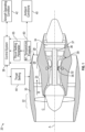
- Figure 1 schematically illustrates a turbine engine assembly 20 including a control system 38 that defines an engine thrust setting 44.
- the example control system 38 determines the engine thrust setting 44 to provide a constant thrust instead of changing thrust based on current operating conditions.
- the engine thrust setting 44 is maintained constant for all altitudes at or below sea level.
- the example turbine engine assembly 20 generally incorporates a fan section 22, a compressor section 24, a combustor section 26 and a turbine section 28 disposed along a common longitudinal axis A.
- the fan section 22 drives air along a bypass flow path B through nacelle 30, while the compressor section 24 drives air along a core flow path C for compression and communication into the combustor section 26.
- Compressed air flow communicated to the combustor section 26 is mixed with fuel from a fuel system 32 and ignited to generate an exhaust gas flow that drives rotation as it expands through the turbine section 28.
- the turbine section 28 is coupled to drive the compressor section 24 through at least one shaft 36.
- the shaft 36 may also drive the fan section 22.
- the turbine section 28 includes at least one rotor 34.
- At least one temperature sensor 35 is provides temperature information for controlling engine operation based on temperature.
- At least one pressure sensor 39 is installed to provide pressure information for controlling engine operation based on pressure.
- At least one speed sensor 37 provides information indicative of a shaft speed.
- Engine operating thrust varies based on ambient conditions 40 and aircraft operating conditions 42 and is modelled by a thrust setting model.
- the ambient conditions 40 include, among other possible things, atmospheric pressure, and ambient temperature.
- Aircraft operating conditions 42 may require engine thrust to be limited. Thrust is therefore, adjusted based on ambient and aircraft conditions 40, 42 by the engine control system 38.
- a thrust setting model is used to associate engine thrust to a measured engine operating parameter 60.
- the thrust setting model is incorporated in the engine control system 38 and defines the thrust setting 44 based on known relationships and/or by way of predefined lookup tables.
- One of the measured engine operating parameters 60 is used as a thrust setting parameter 65 and is monitored and controlled to provide the desired thrust.
- the thrust setting parameter 65 may be any one of the measured engine operating parameters 60 including, for example, a measured rotor/shaft speed (N1), an engine temperature, or a pressure at a location within the engine assembly 20.
- Variations in thrust may correspond with ambient and aircraft conditions 40, 42 and thereby, the required thrust setting parameter 65 is utilized to set the desired thrust and varies with ambient and aircraft conditions 40, 42.
- the control system 38 determines a value for the thrust setting parameter 65 for a given set of ambient conditions 40 based on known relationships and/or by way of predefined lookup tables. Both performing calculations and using a look up table are within the contemplation of this disclosure.
- other means and methods of determining a desired value for the thrust setting parameter 65 could be utilized and are within the contemplation of this disclosure.
- the control system 38 defines settings for the thrust setting parameter 65 that provides the desired thrust at those conditions.
- the thrust setting 44 is then utilized to operate the engine assembly 20 within the defined settings.
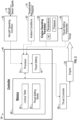
- the control system 38 includes a controller 46 with a processor 54 and memory device 48.
- the example controller 46 relates to a device and system for performing necessary computing or calculation operations of the control system 38.
- the controller 46 may be specially constructed for operation of the control system 38, or it may comprise at least a general-purpose computer selectively activated or reconfigured by software instructions stored in the memory device 48.
- the controller 46 may further be part of full authority digital engine control (FADEC) or an electronic engine controller (EEC).
- FADEC full authority digital engine control
- EEC electronic engine controller
- the software instructions may include a thrust setting model 52 that uses data stored in the memory device 48 in the form of lookup tables schematically indicated at 50 utilized by the processor 54 to define the thrust setting 44.
- the disclosed memory device 48 may include any one or combination of volatile memory elements (e.g., random access memory (RAM, such as DRAM, SRAM, SDRAM, VRAM, etc.) and/or nonvolatile memory elements (e.g., ROM, hard drive, tape, CD-ROM, etc.).
- the software instructions in the memory device 48 may include one or more separate programs, each of which includes an ordered listing of executable instructions for implementing logical functions.
- Software in memory, in whole or in part, is read by the processor 54, and executed to generate the thrust setting 44.
- the thrust setting 44 may be communicated and utilized by a thrust controller 58 to operate the engine according to the defined thrust setting 44.
- the example thrust controller 58 includes all devices that operate to communicate with the engine assembly 20 to generate the thrust based on the thrust setting 44 determined by the processor 54 utilizing the example thrust setting model 52.
- the control system 38 receives information indicative of aircraft operating conditions 42 and ambient conditions 40.
- the information on aircraft operating conditions 42 may be provided by sensor signals 74 indicative of an aircraft operating condition including, among other possible things, aircraft offtakes, aircraft altitude and air speed.
- Information on ambient conditions 40 may be provided by sensor signals 76 from various sensors and systems that provide information including, among other possible things, ambient temperature, and atmospheric pressure.
- the sensor signals 74, 76 may be provided by one or more sensors or sensor systems disposed on the aircraft. Moreover, the sensor signals 74, 76 may be provided through communication with systems external to the aircraft.
- the controller 46 further receives information indicative of a value for at least one of the engine operating parameters 60 utilized as the thrust setting parameter 65.
- the example thrust setting model 52 utilizes information gathered regarding the engine operating parameters 60, ambient conditions 40 and aircraft operating conditions 42 to determine a value of the thrust setting 44.
- the thrust setting model 52 automatically provides the thrust setting 44 that corresponds to the input conditions 40, 42 and 65 according to a defined algorithm. Deviation from the defined thrust setting model 52 for certain operating conditions can require substantial efforts and costs. Accordingly, the disclosed control system 38 provides an alternate means of determined the thrust setting 44 for select operating conditions independent of the thrust setting model 52.
- a prescribed thrust is maintained at a value corresponding to sea level for all altitudes at or below sea level. It should be appreciated that although the disclosed example provides for maintaining a prescribed thrust at a value corresponding with operation at sea level, other altitudes could be utilized and are within the contemplation of this disclosure. Moreover, although the prescribed thrust is maintained with respect to a selected altitude, other aircraft operating parameters could also be utilized for setting the prescribed thrust and are within the contemplation and scope of this disclosure.
- Maintaining a prescribed thrust at altitudes at or below sea level requires changes to the thrust setting parameter 65 that are not provided by the thrust setting model 52. For example, a constant rotor/shaft speed, N1, that provides a given amount of thrust at sea level will provide a different amount of thrust at different altitudes. Accordingly, maintaining a constant thrust corresponding to a thrust at sea level requires an adjustment to how the thrust setting parameter 65 is determined.
- the example control system 38 is configured to adjust values of the thrust setting parameter 65 to maintain a constant thrust for altitudes at or below sea level.
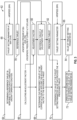
- steps of an example process performed by the example control system 38 are schematically indicated at 62.
- the example control system 38 operates to provide the thrust setting 44 that corresponds with operation at sea level for altitudes below sea level. In other words, rather than changing thrust based on altitude as is performed for altitudes above sea level, the example control system 38 maintains the thrust at the sea level setting for all altitudes below sea level.
- thrust may be maintained at other predefined altitudes and/or for other conditions and remain within the contemplation and scope of this disclosure.
- the setting for the thrust setting parameter 65 that provides a reference thrust at sea level is adjusted to current ambient conditions 40 below sea level.
- the example control system 38 compensates settings for the thrust setting parameter 65 to maintain the prescribed thrust for all altitudes below sea level.
- the control system 38 determines the setting of the thrust setting parameter 65 at sea level for similar operating conditions and determines an adjustment value that is applied to maintain the constant prescribed thrust.
- the control system 38 first determines a reference thrust 78 at sea level that corresponds to a predefined setting of the thrust setting parameter 65 at sea level for a current air speed as is indicated at 64.
- the thrust setting parameter 65 is an engine rotor/shaft speed, N1.
- the desired thrust for various N1 speeds at a specified air speed is predefined in the lookup tables 50 stored in the memory 48 ( Figure 2 ).
- the lookup table 50 includes data for the reference thrust and N1 at sea level for a given air speed.
- the controller 46 determines the reference thrust 78 at sea level based on the N1 speed at sea level from the thrust setting model 52 and the current air speed. The air speed is measured as a Mach number (MN) for current operating conditions.
- MN Mach number
- the example method continues by calculating an adjustment factor that provides for adjusting the determined sea level reference thrust 78 based on the current altitude of the aircraft and is indicated at 66.
- the adjustment factor is determined, at least partially, by a calculation including a ratio of a pressure at sea level and a pressure at a current altitude below sea level.
- the pressure at sea level (Psl) is determined and utilized to determine the adjustment factor.
- the pressure at the current altitude (Pamb) is information continually determined and/or measured by sensors 76 and communicated to the control system 38.
- a ratio of Psl/Pamb is utilized as part of a relationship to determine an adjustment factor.
- the adjustment factor 80 provides for adjusting the reference thrust 78 based on the current altitude of the aircraft.
- Equation 1 is disclosed by way of example, the adjustment factor 80 may be determined utilizing other criteria indicative of differences between actual aircraft operating conditions and operating conditions at sea level.
- additional variables may be utilized with Equation 1 to tailor the determination of the adjustment factor 80 to application specific factors. For example, aircraft specific features and/or unique ambient conditions may be compensated by additional variables and is within the contemplation and scope of this disclosure.
- the determined adjustment factor 80 represents a relationship between operation at current conditions and operation at sea level.
- the relationship may also be represented as some percentage or fraction of the current reference condition.
- the adjustment factor 80 is calculated, it is applied to the reference thrust 78 as indicated in step 68.
- Application of the adjustment factor 80 provides for the definition of a prescribed thrust 82.
- the prescribed thrust 82 represents the thrust for the current altitude that provides the thrust that would correspond to operation at sea level.
- the prescribed thrust 82 is the desired setting and is implemented by controlling the thrust setting parameter 65.
- a value of the thrust setting parameter 65 that provides prescribed thrust 82 is determined as indicated at 70.
- the rotor/shaft speed N1 is utilized as the thrust setting parameter 65 and is determined with the predefined data set provided as a lookup table 50.
- the prescribed thrust 82 is utilized with the predefined lookup tables 50 to determine a value 84 of the thrust setting parameter 65 that corresponds with the prescribed thrust 82.
- the value 84 of the thrust setting parameter 65 is then utilized for operation of the aircraft engine as is schematically indicated at 72.
- the value 84 of the thrust setting parameter 65 is a shaft/rotor speed, N1.
- the thrust setting parameter 65 may be a measured pressure and/or temperature at a location within the engine assembly 20.
- the controller 46 repeats the method steps 62 to update the value 84 of the thrust setting parameter 65 for changes in aircraft operation including changes in altitude.
- a method of controlling an aircraft engine 20 with an engine control system 38 to set a prescribed thrust 82 at a selected aircraft operating parameter independent of a thrust setting model 52 that determines thrust based on a current aircraft operating parameter includes, among other possible things, determining a reference thrust 78 that corresponds to a thrust setting parameter 65 at the selected aircraft operating parameter for a current airspeed according to a predefined relationship, calculating an adjustment factor 80 based on a relationship between the current aircraft operating parameter and the selected aircraft operating parameter, determining the prescribed thrust 82 at the current aircraft operating parameter by applying the adjustment factor 80 to the reference thrust 78, determining a value of the thrust setting parameter 65 that provides the prescribed thrust 82 at the current aircraft operating parameter according to a predefined relationship between the reference thrust 78 and the current airspeed, and operating the engine 20 based on the determined value of the thrust setting parameter 65 to provide the prescribed thrust 82.
- the selected aircraft operating parameter includes a sea level altitude and the current aircraft operating parameter includes the current altitude.
- the thrust setting model 52 is configured for determining a thrust based on the current altitude for altitudes above sea level and the prescribed thrust 82 is determined independent of the thrust setting model 52 to provide a constant thrust for altitudes below sea level.
- the method further includes determining the thrust based on the thrust setting model 52 in response to the aircraft operating at an altitude above sea level.
- determining the reference thrust 78 corresponds to the thrust setting parameter 65 according to a predefined relationship includes looking up the reference thrust 78 that corresponds to the current air speed, and the thrust setting parameter 65 in a look-up table 50.
- determining the thrust setting parameter 65 value that corresponds with the prescribed thrust 82 at the current airspeed includes looking up the thrust setting parameter 65 value that corresponds with the prescribed thrust 82 at the current airspeed in a look-up table 50.
- the thrust setting parameter 65 includes a rotational speed of an engine shaft 36.
- the thrust setting parameter 65 includes at least one of a measured engine operating temperature and a measured engine operating pressure.
- calculating the adjustment factor 80 is based on a measured ambient pressure at the current altitude and a determined ambient pressure at sea level.
- a method of controlling an aircraft engine 20 with an engine control system 38 to maintain a prescribed engine thrust 82 at a value that corresponds to operation at sea level independent of a current altitude of an aircraft includes, among other possible things, determining a reference thrust 78 that corresponds to a value of a thrust setting parameter 65 at sea level for a current air speed according to a predefined relationship in response to operation below sea level, calculating an adjustment factor 80 based on a relationship between a current altitude and sea level, determining the prescribed engine thrust 82 at the current altitude by applying the adjustment factor 80 to the reference thrust 78, determining the value of the thrust setting parameter 65 that provides the prescribed engine thrust 82 at sea level according to a predefined relationship of the reference thrust 78 and the current airspeed, and operating the engine 20 based on the determined value of the thrust setting parameter 65 to provide the prescribed engine thrust 82.
- determining the reference thrust 78 that corresponds to the value of the thrust setting parameter 65 at sea level according to a predefined relationship includes looking up the reference thrust 78 that corresponds to the current airspeed and the value of the thrust setting parameter 65 in a look-up table 50.
- determining the value of the thrust setting parameter 65 that provides the prescribed engine thrust 82 at sea level according to the predefined relationship includes looking up the value of the thrust setting parameter 65 that corresponds to the prescribed thrust 82 and the current airspeed in a look-up table 50.
- the thrust setting parameter 65 includes a rotational speed of an engine shaft 36.
- the thrust setting parameter 65 includes at least one of a measured engine operating temperature and a measured engine operating pressure.
- calculating the adjustment factor 80 is at least partially based on a measured ambient pressure at the current altitude and a determined ambient pressure at sea level.
- a control system 38 for an aircraft engine 20 includes, among other possible things, a controller 46 that includes a processor 54 and a memory 48 for storing engine operating settings that are indicative of a prescribed thrust 82 based on a thrust setting parameter 65 and an aircraft operating condition, the controller 46 is programmed to receive information indicative of the thrust setting parameter 65 and the aircraft operating condition from at least one sensor 35, 37 and 39 that is associated with an aircraft engine 20, to set the prescribed thrust 82 at a selected aircraft operating parameter independent of a thrust setting model 52 by determining a reference thrust 78 that corresponds to a value of the thrust setting parameter 65 at the selected aircraft operating parameter for a current aircraft operating condition according to a predefined relationship in response to operation at a threshold aircraft operating condition, to calculate an adjustment factor 80 based on a difference between a current aircraft operating parameter and the selected aircraft operating parameter, to determine the prescribed thrust 82 at the current aircraft operating parameter by applying the adjustment factor 80 to the reference thrust 78, and to determine a value of the thrust setting parameter that provides the prescribed thrust 82 at the
- the selected aircraft operating parameter includes a sea level altitude and the threshold aircraft operating condition includes operation at an altitude at or below sea level.
- the thrust setting model 52 is configured for determining a thrust based on a current altitude for altitudes above sea level and the prescribed thrust 82 is determined independent of the thrust setting model 52 to provide a constant thrust at altitudes at or below sea level.
- the controller 46 includes look-up tables 50 that include predefined relationships between the reference thrust 78, the thrust setting parameter 65 and airspeed and the controller 46 is further programmed to determine the reference thrust 78 and the thrust setting parameter 65 utilizing the look-up tables 50.
- the thrust setting parameter 65 includes at least one of a rotational speed of an engine shaft 36, a measured engine operating temperature and a measured engine operating pressure.
- the example control system 38 and method provides a constant prescribed thrust 82 for all altitudes below sea level that corresponds to a thrust at sea level for current operating conditions.
Landscapes
- Engineering & Computer Science (AREA)
- Chemical & Material Sciences (AREA)
- Combustion & Propulsion (AREA)
- Aviation & Aerospace Engineering (AREA)
- Mechanical Engineering (AREA)
- General Engineering & Computer Science (AREA)
- Feedback Control In General (AREA)
- Combined Controls Of Internal Combustion Engines (AREA)
- Control Of Vehicle Engines Or Engines For Specific Uses (AREA)
Applications Claiming Priority (1)
| Application Number | Priority Date | Filing Date | Title |
|---|---|---|---|
| US18/307,160 US20240359806A1 (en) | 2023-04-26 | 2023-04-26 | Aircraft engine control system for maintaining constant thrust below sea level |
Publications (2)
| Publication Number | Publication Date |
|---|---|
| EP4455469A2 true EP4455469A2 (de) | 2024-10-30 |
| EP4455469A3 EP4455469A3 (de) | 2025-01-15 |
Family
ID=90924464
Family Applications (1)
| Application Number | Title | Priority Date | Filing Date |
|---|---|---|---|
| EP24172836.9A Pending EP4455469A3 (de) | 2023-04-26 | 2024-04-26 | Flugzeugtriebwerksteuerungssystem zur aufrechterhaltung eines konstanten schubs unter dem meeresspiegel |
Country Status (3)
| Country | Link |
|---|---|
| US (1) | US20240359806A1 (de) |
| EP (1) | EP4455469A3 (de) |
| CA (1) | CA3232841A1 (de) |
Family Cites Families (1)
| Publication number | Priority date | Publication date | Assignee | Title |
|---|---|---|---|---|
| US4275557A (en) * | 1978-01-25 | 1981-06-30 | General Electric Company | Method and apparatus for controlling thrust in a gas turbine engine |
-
2023
- 2023-04-26 US US18/307,160 patent/US20240359806A1/en active Pending
-
2024
- 2024-03-21 CA CA3232841A patent/CA3232841A1/en active Pending
- 2024-04-26 EP EP24172836.9A patent/EP4455469A3/de active Pending
Also Published As
| Publication number | Publication date |
|---|---|
| US20240359806A1 (en) | 2024-10-31 |
| EP4455469A3 (de) | 2025-01-15 |
| CA3232841A1 (en) | 2025-06-23 |
Similar Documents
| Publication | Publication Date | Title |
|---|---|---|
| EP3147220B1 (de) | Systeme und verfahren zur einhebel-turbopropsteuerung unter verwendung drehmomentbasierter und leistungsbasierter zeitplanung | |
| US9732625B2 (en) | System and method for controlling a gas turbine engine | |
| US10961921B2 (en) | Model-based control system and method for a turboprop engine | |
| CA3011878C (en) | Method of controlling gas generator power and torque output | |
| US5051918A (en) | Gas turbine stall/surge identification and recovery | |
| US20130184961A1 (en) | Methods and systems for managing power of an engine | |
| US20160069277A1 (en) | Turboshaft engine control | |
| EP2813686B1 (de) | Motorbetriebunterstützungssystem für eine Gasturbine | |
| JPS6132484B2 (de) | ||
| US9815568B2 (en) | Device for monitoring a power transmission system of an aircraft, an aircraft provided with the device, and the method used | |
| EP3712074B1 (de) | Verfahren und system zum einstellen der leistung eines flugzeugmotors | |
| EP3279450B1 (de) | System und verfahren für einen motorenregler auf basis der beschleunigungsleistung | |
| US20150285159A1 (en) | Method and a device for adjusting a setpoint value of a parameter that influences thrust from a gas turbine engine | |
| CN110199102B (zh) | 燃气涡轮发动机燃料控制系统和方法 | |
| EP3020943A1 (de) | Optimale schubsteuerung eines flugzeugmotors | |
| Csank et al. | Enhanced engine performance during emergency operation using a model-based engine control architecture | |
| US12140085B2 (en) | System and method for detecting and accommodating loss of torque on gas turbine engines | |
| EP4455469A2 (de) | Flugzeugtriebwerksteuerungssystem zur aufrechterhaltung eines konstanten schubs unter dem meeresspiegel | |
| US10946972B2 (en) | Method and system for controlling thrust of an engine | |
| EP3623608B1 (de) | Verfahren und system zur einstellung eines variablen geometriemechanismus | |
| EP4442979A1 (de) | Systeme und verfahren zur einstellung einer modulationseigenschaft eines abblasventils eines gasturbinenmotors |
Legal Events
| Date | Code | Title | Description |
|---|---|---|---|
| PUAI | Public reference made under article 153(3) epc to a published international application that has entered the european phase |
Free format text: ORIGINAL CODE: 0009012 |
|
| STAA | Information on the status of an ep patent application or granted ep patent |
Free format text: STATUS: THE APPLICATION HAS BEEN PUBLISHED |
|
| AK | Designated contracting states |
Kind code of ref document: A2 Designated state(s): AL AT BE BG CH CY CZ DE DK EE ES FI FR GB GR HR HU IE IS IT LI LT LU LV MC ME MK MT NL NO PL PT RO RS SE SI SK SM TR |
|
| PUAL | Search report despatched |
Free format text: ORIGINAL CODE: 0009013 |
|
| AK | Designated contracting states |
Kind code of ref document: A3 Designated state(s): AL AT BE BG CH CY CZ DE DK EE ES FI FR GB GR HR HU IE IS IT LI LT LU LV MC ME MK MT NL NO PL PT RO RS SE SI SK SM TR |
|
| RIC1 | Information provided on ipc code assigned before grant |
Ipc: F02C 9/28 20060101AFI20241211BHEP |
|
| STAA | Information on the status of an ep patent application or granted ep patent |
Free format text: STATUS: REQUEST FOR EXAMINATION WAS MADE |
|
| 17P | Request for examination filed |
Effective date: 20250715 |