EP4455462A1 - Diagnostic device for exhaust gas aftertreatment device, diagnostic method for exhaust gas aftertreatment device, and diagnostic program for exhaust gas aftertreatment device - Google Patents
Diagnostic device for exhaust gas aftertreatment device, diagnostic method for exhaust gas aftertreatment device, and diagnostic program for exhaust gas aftertreatment device Download PDFInfo
- Publication number
- EP4455462A1 EP4455462A1 EP23749601.3A EP23749601A EP4455462A1 EP 4455462 A1 EP4455462 A1 EP 4455462A1 EP 23749601 A EP23749601 A EP 23749601A EP 4455462 A1 EP4455462 A1 EP 4455462A1
- Authority
- EP
- European Patent Office
- Prior art keywords
- exhaust gas
- gas aftertreatment
- filter
- aftertreatment device
- diagnostic
- Prior art date
- Legal status (The legal status is an assumption and is not a legal conclusion. Google has not performed a legal analysis and makes no representation as to the accuracy of the status listed.)
- Pending
Links
Images



Classifications
-
- F—MECHANICAL ENGINEERING; LIGHTING; HEATING; WEAPONS; BLASTING
- F02—COMBUSTION ENGINES; HOT-GAS OR COMBUSTION-PRODUCT ENGINE PLANTS
- F02D—CONTROLLING COMBUSTION ENGINES
- F02D35/00—Controlling engines, dependent on conditions exterior or interior to engines, not otherwise provided for
- F02D35/0015—Controlling engines, dependent on conditions exterior or interior to engines, not otherwise provided for using exhaust gas sensors
-
- F—MECHANICAL ENGINEERING; LIGHTING; HEATING; WEAPONS; BLASTING
- F01—MACHINES OR ENGINES IN GENERAL; ENGINE PLANTS IN GENERAL; STEAM ENGINES
- F01N—GAS-FLOW SILENCERS OR EXHAUST APPARATUS FOR MACHINES OR ENGINES IN GENERAL; GAS-FLOW SILENCERS OR EXHAUST APPARATUS FOR INTERNAL-COMBUSTION ENGINES
- F01N11/00—Monitoring or diagnostic devices for exhaust-gas treatment apparatus
- F01N11/002—Monitoring or diagnostic devices for exhaust-gas treatment apparatus the diagnostic devices measuring or estimating temperature or pressure in, or downstream of the exhaust apparatus
-
- F—MECHANICAL ENGINEERING; LIGHTING; HEATING; WEAPONS; BLASTING
- F01—MACHINES OR ENGINES IN GENERAL; ENGINE PLANTS IN GENERAL; STEAM ENGINES
- F01N—GAS-FLOW SILENCERS OR EXHAUST APPARATUS FOR MACHINES OR ENGINES IN GENERAL; GAS-FLOW SILENCERS OR EXHAUST APPARATUS FOR INTERNAL-COMBUSTION ENGINES
- F01N3/00—Exhaust or silencing apparatus having means for purifying, rendering innocuous, or otherwise treating exhaust
-
- F—MECHANICAL ENGINEERING; LIGHTING; HEATING; WEAPONS; BLASTING
- F01—MACHINES OR ENGINES IN GENERAL; ENGINE PLANTS IN GENERAL; STEAM ENGINES
- F01N—GAS-FLOW SILENCERS OR EXHAUST APPARATUS FOR MACHINES OR ENGINES IN GENERAL; GAS-FLOW SILENCERS OR EXHAUST APPARATUS FOR INTERNAL-COMBUSTION ENGINES
- F01N3/00—Exhaust or silencing apparatus having means for purifying, rendering innocuous, or otherwise treating exhaust
- F01N3/02—Exhaust or silencing apparatus having means for purifying, rendering innocuous, or otherwise treating exhaust for cooling, or for removing solid constituents of, exhaust
- F01N3/021—Exhaust or silencing apparatus having means for purifying, rendering innocuous, or otherwise treating exhaust for cooling, or for removing solid constituents of, exhaust by means of filters
-
- F—MECHANICAL ENGINEERING; LIGHTING; HEATING; WEAPONS; BLASTING
- F01—MACHINES OR ENGINES IN GENERAL; ENGINE PLANTS IN GENERAL; STEAM ENGINES
- F01N—GAS-FLOW SILENCERS OR EXHAUST APPARATUS FOR MACHINES OR ENGINES IN GENERAL; GAS-FLOW SILENCERS OR EXHAUST APPARATUS FOR INTERNAL-COMBUSTION ENGINES
- F01N3/00—Exhaust or silencing apparatus having means for purifying, rendering innocuous, or otherwise treating exhaust
- F01N3/02—Exhaust or silencing apparatus having means for purifying, rendering innocuous, or otherwise treating exhaust for cooling, or for removing solid constituents of, exhaust
- F01N3/021—Exhaust or silencing apparatus having means for purifying, rendering innocuous, or otherwise treating exhaust for cooling, or for removing solid constituents of, exhaust by means of filters
- F01N3/023—Exhaust or silencing apparatus having means for purifying, rendering innocuous, or otherwise treating exhaust for cooling, or for removing solid constituents of, exhaust by means of filters using means for regenerating the filters, e.g. by burning trapped particles
-
- F—MECHANICAL ENGINEERING; LIGHTING; HEATING; WEAPONS; BLASTING
- F02—COMBUSTION ENGINES; HOT-GAS OR COMBUSTION-PRODUCT ENGINE PLANTS
- F02D—CONTROLLING COMBUSTION ENGINES
- F02D45/00—Electrical control not provided for in groups F02D41/00 - F02D43/00
-
- G—PHYSICS
- G06—COMPUTING OR CALCULATING; COUNTING
- G06F—ELECTRIC DIGITAL DATA PROCESSING
- G06F21/00—Security arrangements for protecting computers, components thereof, programs or data against unauthorised activity
- G06F21/60—Protecting data
- G06F21/64—Protecting data integrity, e.g. using checksums, certificates or signatures
-
- F—MECHANICAL ENGINEERING; LIGHTING; HEATING; WEAPONS; BLASTING
- F01—MACHINES OR ENGINES IN GENERAL; ENGINE PLANTS IN GENERAL; STEAM ENGINES
- F01N—GAS-FLOW SILENCERS OR EXHAUST APPARATUS FOR MACHINES OR ENGINES IN GENERAL; GAS-FLOW SILENCERS OR EXHAUST APPARATUS FOR INTERNAL-COMBUSTION ENGINES
- F01N2560/00—Exhaust systems with means for detecting or measuring exhaust gas components or characteristics
- F01N2560/06—Exhaust systems with means for detecting or measuring exhaust gas components or characteristics the means being a temperature sensor
-
- F—MECHANICAL ENGINEERING; LIGHTING; HEATING; WEAPONS; BLASTING
- F01—MACHINES OR ENGINES IN GENERAL; ENGINE PLANTS IN GENERAL; STEAM ENGINES
- F01N—GAS-FLOW SILENCERS OR EXHAUST APPARATUS FOR MACHINES OR ENGINES IN GENERAL; GAS-FLOW SILENCERS OR EXHAUST APPARATUS FOR INTERNAL-COMBUSTION ENGINES
- F01N2590/00—Exhaust or silencing apparatus adapted to particular use, e.g. for military applications, airplanes, submarines
- F01N2590/08—Exhaust or silencing apparatus adapted to particular use, e.g. for military applications, airplanes, submarines for heavy duty applications, e.g. trucks, buses, tractors, locomotives
-
- F—MECHANICAL ENGINEERING; LIGHTING; HEATING; WEAPONS; BLASTING
- F01—MACHINES OR ENGINES IN GENERAL; ENGINE PLANTS IN GENERAL; STEAM ENGINES
- F01N—GAS-FLOW SILENCERS OR EXHAUST APPARATUS FOR MACHINES OR ENGINES IN GENERAL; GAS-FLOW SILENCERS OR EXHAUST APPARATUS FOR INTERNAL-COMBUSTION ENGINES
- F01N2900/00—Details of electrical control or of the monitoring of the exhaust gas treating apparatus
- F01N2900/06—Parameters used for exhaust control or diagnosing
- F01N2900/14—Parameters used for exhaust control or diagnosing said parameters being related to the exhaust gas
- F01N2900/1406—Exhaust gas pressure
-
- F—MECHANICAL ENGINEERING; LIGHTING; HEATING; WEAPONS; BLASTING
- F01—MACHINES OR ENGINES IN GENERAL; ENGINE PLANTS IN GENERAL; STEAM ENGINES
- F01N—GAS-FLOW SILENCERS OR EXHAUST APPARATUS FOR MACHINES OR ENGINES IN GENERAL; GAS-FLOW SILENCERS OR EXHAUST APPARATUS FOR INTERNAL-COMBUSTION ENGINES
- F01N2900/00—Details of electrical control or of the monitoring of the exhaust gas treating apparatus
- F01N2900/06—Parameters used for exhaust control or diagnosing
- F01N2900/16—Parameters used for exhaust control or diagnosing said parameters being related to the exhaust apparatus, e.g. particulate filter or catalyst
-
- F—MECHANICAL ENGINEERING; LIGHTING; HEATING; WEAPONS; BLASTING
- F01—MACHINES OR ENGINES IN GENERAL; ENGINE PLANTS IN GENERAL; STEAM ENGINES
- F01N—GAS-FLOW SILENCERS OR EXHAUST APPARATUS FOR MACHINES OR ENGINES IN GENERAL; GAS-FLOW SILENCERS OR EXHAUST APPARATUS FOR INTERNAL-COMBUSTION ENGINES
- F01N2900/00—Details of electrical control or of the monitoring of the exhaust gas treating apparatus
- F01N2900/06—Parameters used for exhaust control or diagnosing
- F01N2900/16—Parameters used for exhaust control or diagnosing said parameters being related to the exhaust apparatus, e.g. particulate filter or catalyst
- F01N2900/1602—Temperature of exhaust gas apparatus
-
- F—MECHANICAL ENGINEERING; LIGHTING; HEATING; WEAPONS; BLASTING
- F01—MACHINES OR ENGINES IN GENERAL; ENGINE PLANTS IN GENERAL; STEAM ENGINES
- F01N—GAS-FLOW SILENCERS OR EXHAUST APPARATUS FOR MACHINES OR ENGINES IN GENERAL; GAS-FLOW SILENCERS OR EXHAUST APPARATUS FOR INTERNAL-COMBUSTION ENGINES
- F01N2900/00—Details of electrical control or of the monitoring of the exhaust gas treating apparatus
- F01N2900/06—Parameters used for exhaust control or diagnosing
- F01N2900/16—Parameters used for exhaust control or diagnosing said parameters being related to the exhaust apparatus, e.g. particulate filter or catalyst
- F01N2900/1606—Particle filter loading or soot amount
-
- Y—GENERAL TAGGING OF NEW TECHNOLOGICAL DEVELOPMENTS; GENERAL TAGGING OF CROSS-SECTIONAL TECHNOLOGIES SPANNING OVER SEVERAL SECTIONS OF THE IPC; TECHNICAL SUBJECTS COVERED BY FORMER USPC CROSS-REFERENCE ART COLLECTIONS [XRACs] AND DIGESTS
- Y02—TECHNOLOGIES OR APPLICATIONS FOR MITIGATION OR ADAPTATION AGAINST CLIMATE CHANGE
- Y02T—CLIMATE CHANGE MITIGATION TECHNOLOGIES RELATED TO TRANSPORTATION
- Y02T10/00—Road transport of goods or passengers
- Y02T10/10—Internal combustion engine [ICE] based vehicles
- Y02T10/40—Engine management systems
Definitions
- the present invention relates to a diagnostic device for an exhaust gas aftertreatment device, a diagnostic method for an exhaust gas aftertreatment device, and a diagnostic program for an exhaust gas aftertreatment device, the diagnostic device, the diagnostic method, and the diagnostic program diagnosing a malfunction in an exhaust gas aftertreatment device provided in a vehicle.
- Patent Literature 1 discloses a particulate filter malfunction diagnostic device that determines a malfunction in a particulate filter based on a deposition amount of particulate matter (PM).
- a PM sensor detects the deposition amount of PM based on a change in electric resistance between a pair of electrodes.
- Patent Literature 2 discloses a diagnostic device that includes a PM sensor including at least a pair of electrode members forming a capacitor, the PM sensor being provided in a filter member disposed downstream of a diesel particulate filter (DPF), and that determines a malfunction in the DPF based on electrostatic capacitance between the electrode members.
- a PM sensor including at least a pair of electrode members forming a capacitor, the PM sensor being provided in a filter member disposed downstream of a diesel particulate filter (DPF), and that determines a malfunction in the DPF based on electrostatic capacitance between the electrode members.
- DPF diesel particulate filter
- Patent Literature 1 With the PM sensor of Patent Literature 1, a great change in an output is inevitable due to adhesion of PM having a large particle size to a portion between the pair of electrode members. Further, in Patent Literature 2, a capacitor has to be added, and an improvement in DPF is necessary.
- An object of the present invention is to provide a diagnostic device for an exhaust gas aftertreatment device, a diagnostic method for the exhaust gas aftertreatment device, and a diagnostic program for the exhaust gas aftertreatment device, the diagnostic device, diagnostic method, and diagnostic program being capable of detecting a malfunction in the exhaust gas aftertreatment device with high accuracy.
- a diagnostic device for an exhaust gas aftertreatment device that has a filter for collecting fine particles from exhaust gas of an engine and is provided in a vehicle, the diagnostic device diagnosing a malfunction in the exhaust gas aftertreatment device, the diagnostic device including: a temperature detection device that detects a filter inlet-side temperature and a filter outlet-side temperature; a differential pressure detection device that detects a differential pressure between a filter inlet-side pressure and a filter outlet-side pressure; an intake air pressure detection device that detects an intake air pressure of the engine; and a controller that determines a malfunction in the exhaust gas aftertreatment device based on values detected by the temperature detection device, the differential pressure detection device, and the intake air pressure detection device.
- a diagnostic method for an exhaust gas aftertreatment device that has a filter for collecting fine particles from exhaust gas of an engine and is provided in a vehicle, the diagnostic method for diagnosing a malfunction in the exhaust gas aftertreatment device, the diagnostic method including: a temperature detection step of detecting a filter inlet-side temperature and a filter outlet-side temperature; a differential pressure detection step of detecting a differential pressure between a filter inlet-side pressure and a filter outlet-side pressure; an intake air pressure detection step of detecting an intake air pressure of the engine; and a determination step of determining a malfunction in the exhaust gas aftertreatment device based on values detected in the temperature detection step, the differential pressure detection step, and the intake air pressure detection step.
- a diagnostic program for an exhaust gas aftertreatment device that has a filter for collecting fine particles from exhaust gas of an engine and is provided in a vehicle, the diagnostic program for causing a computer to diagnose a malfunction in the exhaust gas aftertreatment device, the diagnostic program including causing the computer to determine a malfunction in the exhaust gas aftertreatment device based on a filter inlet-side temperature, a filter outlet-side temperature, a differential pressure between a filter inlet-side pressure and a filter outlet-side pressure, and an intake air pressure of the engine.
- a malfunction in the exhaust gas aftertreatment device is determined based on the filter inlet-side temperature, the filter outlet-side temperature, the differential pressure between the filter inlet-side pressure and the filter outlet-side pressure, and the intake air pressure of the engine.
- the deposition amount of fine particles deposited on the filter can be obtained from the differential pressure between the filter inlet-side pressure and the filter outlet-side pressure.
- a temperature state of the filter is obtained from the filter inlet-side temperature and the filter outlet-side temperature. Therefore, before the filter is damaged by melting, a malfunction in the exhaust gas aftertreatment device can be detected by using the differential pressure between the filter inlet-side pressure and the filter outlet-side pressure, the filter inlet-side temperature, and the filter outlet-side temperature for determination.
- the outputs from the temperature detection device, the differential pressure detection device, and the intake air pressure detection device do not change significantly. Therefore, the malfunction in the exhaust gas aftertreatment device can be detected with high accuracy.
- a diagnostic device (diagnostic device 1) for an exhaust gas aftertreatment device diagnoses a malfunction in the exhaust gas aftertreatment device provided in a vehicle.
- FIG. 1 which is a side view of a work machine 20, the diagnostic device 1 is provided in the work machine 20.
- the work machine 20 is one example of a vehicle, and is, for example, a hydraulic excavator.
- the work machine 20 may be operated by an operator in a cab 23, may be remotely operated, or may be automatically operated.
- the work machine 20 has a machine main body 25 including a lower travelling body 21 and an upper slewing body 22, an attachment 30, and cylinders 40.
- the lower travelling body 21 is a portion that causes the work machine 20 to travel, and includes, for example, right and left crawlers 26.
- the upper slewing body 22 is slewably attached to an upper part of the lower travelling body 21 via a slewing device 24.
- the cab 23 is provided at a front part of the upper slewing body 22.
- the attachment 30 is attached to the upper slewing body 22 to be rotatable in an up-and-down direction.
- the attachment 30 includes a boom 31, an arm 32, and a bucket 33.
- the boom 31 is attached to the upper slewing body 22 to be rotatable in the up-and-down direction (capable of being raised and lowered).
- the arm 32 is attached to the boom 31 to be rotatable in the up-and-down direction.
- the bucket 33 is attached to the arm 32 to be rotatable in a frontand-rear direction.
- the bucket 33 is a tip attachment that is a tip portion of the attachment 30, and is a part that performs work such as excavation, leveling, and scooping of earth and sand.
- a work object to be held by the bucket 33 is not limited to earth and sand, but may also be stones or waste (such as industrial waste).
- the tip attachment is not limited to the bucket 33, and may be a grapple, a lifting magnet, or the like.
- the cylinders 40 can hydraulically turn the attachment 30.
- the cylinders 40 are hydraulic telescopic cylinders.
- the cylinders 40 include a boom cylinder 41, an arm cylinder 42, and a bucket cylinder 43.
- the boom cylinder 41 rotates the boom 31 with respect to the upper slewing body 22.
- the boom cylinder 41 has a base end portion rotatably attached to the upper slewing body 22.
- the boom cylinder 41 has a tip portion rotatably attached to the boom 31.
- the arm cylinder 42 rotates the arm 32 with respect to the boom 31.
- the arm cylinder 42 has a base end portion rotatably attached to the boom 31.
- the arm cylinder 42 has a tip portion rotatably attached to the arm 32.
- the bucket cylinder 43 rotates the bucket 33 with respect to the arm 32.
- the bucket cylinder 43 has a base end portion rotatably attached to the arm 32.
- the bucket cylinder 43 has a tip portion rotatably attached to a link member 34 rotatably attached to the bucket 33.
- the work machine 20 includes an engine 51, a hydraulic pump 52, and a control valve group 53.
- the engine 51 is a power source of the work machine 20.
- the hydraulic pump 52 is driven by the engine 51.
- the hydraulic pump 52 includes a left hydraulic pump 52L and a right hydraulic pump 52R.
- the control valve group 53 changes a flow rate of hydraulic oil supplied from the hydraulic pump 52 to the cylinders 40 and the like.
- the control valve group 53 includes a left control valve group 53L and a right control valve group 53R.
- the left hydraulic pump 52L supplies hydraulic oil to each of a left traveling motor 54L, a slewing motor 55, and the arm cylinder 42.
- the right hydraulic pump 52R supplies hydraulic oil to each of a right traveling motor 54R, the boom cylinder 41, and the bucket cylinder 43.
- FIG. 2 illustrates one example of the arrangement of these components, and the arrangement of these components is not limited to FIG. 2 .
- the left traveling motor 54L drives the left crawler 26 of the lower travelling body 21, and the right traveling motor 54R drives the right crawler 26 of the lower travelling body 21.
- the slewing motor 55 is provided in the slewing device 24 and slews the upper slewing body 22.
- the left control valve group 53L includes a control valve that changes the flow rate of the hydraulic oil supplied to the left traveling motor 54L, a control valve that changes the flow rate of the hydraulic oil supplied to the slewing motor 55, and a control valve that changes the flow rate of the hydraulic oil supplied to the arm cylinder 42.
- the right control valve group 53R includes a control valve that changes the flow rate of the hydraulic oil supplied to the right traveling motor 54R, a control valve that changes the flow rate of the hydraulic oil supplied to the boom cylinder 41, and a control valve that changes the flow rate of the hydraulic oil supplied to the bucket cylinder 43.
- These control valves are controlled by a controller 71 in response to an operation supplied to an operation device 28 (see FIG. 1 ) including at least one operation lever provided in the cab 23.
- the operation device 28 includes a plurality of operation levers, and these operation levers are disposed in the cab 23.
- the engine 51, the hydraulic pump 52, and the control valve group 53 are controlled by the controller 71 described later.
- the left and right crawlers 26, the upper slewing body 22, and the attachment 30 are movable portions of the work machine 20.
- the operation device 28 outputs operation commands for operating the movable portions.
- the engine 51, the hydraulic pump 52, and the control valve group 53 are power sources that supply power to the movable portions.
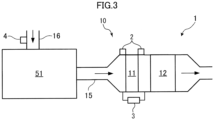
- the work machine 20 includes the exhaust gas aftertreatment device 10.
- the exhaust gas aftertreatment device 10 is provided in an exhaust pipe 15 through which an exhaust gas of the engine 51 passes, and collects fine particles from the exhaust gas.
- the exhaust gas aftertreatment device 10 includes a filter 11 that collects fine particles, and an oxidation catalyst 12 that is provided downstream of the filter 11 and oxidizes unburnt fuel.
- the diagnostic device 1 includes temperature sensors 2 (one example of a temperature detection device), a differential pressure sensor 3 (one example of a differential pressure detection device), and an intake air pressure sensor 4 (one example of an intake air pressure detection device).
- the temperature sensors 2 respectively detect a filter inlet-side temperature and a filter outlet-side temperature.
- the differential pressure sensor 3 detects a filter inlet-side pressure, a filter outlet-side pressure, and a differential pressure (for example, a differential pressure between an inlet side and an outlet side of the filter 11).
- the intake air pressure sensor 4 is provided in an intake air pipe 16 that supplies air to the engine 51, and detects an intake air pressure (boost pressure) of the engine 51.
- the filter inlet-side temperature is a temperature detected by the temperature sensor 2 disposed at an exhaust gas inlet of the filter 11 or near the inlet.
- the filter inlet-side temperature may be a temperature of the exhaust gas at the inlet of the filter 11 or the temperature of the filter 11 at the inlet of the filter 11.
- the filter inlet-side temperature may be a temperature of the exhaust gas near the inlet upstream of the inlet of the filter 11 or a temperature of the pipe near the inlet upstream of the inlet of the filter 11.
- the filter outlet-side temperature is a temperature detected by the temperature sensor 2 disposed at the exhaust gas outlet of the filter 11 or near the outlet.
- the filter outlet-side temperature may be a temperature of the exhaust gas at the outlet of the filter 11 or a temperature of the filter 11 at the outlet of the filter 11.
- the filter outlet-side temperature may be a temperature of the exhaust gas near the outlet downstream of the outlet of the filter 11, or may be a temperature of the pipe near the outlet downstream of the outlet of the filter 11.
- the filter inlet-side pressure may be a pressure at the inlet of the filter 11, or may be a pressure near the inlet upstream of the inlet of the filter 11.
- the filter outlet-side pressure may be a pressure at the outlet of the filter 11, or may be a pressure near the outlet downstream of the outlet of the filter 11.
- the work machine 20 includes the controller 71, a storage device 73, and a communication device 74.
- the controller 71 includes a computer that inputs and outputs signals, performs arithmetic (processing), stores information, and the like.
- the controller 71 includes determination means, notification means, limiting means, accumulated time calculation means, and security processing means, described later. Functions of the determination means, the notification means, the limiting means, the accumulated time calculation means, and the security processing means in the controller 71 are implemented by executing programs stored in the storage unit (not illustrated) of the controller 71.
- the controller 71 may be provided at only one place or may be provided separately at a plurality of places.
- the controller 71 may be mounted on the work machine 20 or may be disposed in a server or the like outside the work machine 20.
- the diagnostic device 1 includes the controller 71.
- the controller 71 receives the temperature values respectively detected by the temperature sensors 2.
- the controller 71 handles, for example, a temperature value expressed as an absolute temperature. Further, the controller 71 receives a differential pressure value detected by the differential pressure sensor 3. Further, the controller 71 receives a pressure value detected by the intake air pressure sensor 4. The controller 71 periodically acquires the temperature values respectively detected by the temperature sensors 2, the differential pressure value detected by the differential pressure sensor 3, and the pressure value detected by the intake air pressure sensor 4.
- controller 71 receives an operation command from the operation device 28.
- the communication device 74 can transmit and receive data by performing communication such as wireless communication or wired communication with a server or the like outside the work machine 20.
- the controller 71 determines a malfunction in the exhaust gas aftertreatment device 10 based on the values detected respectively by the temperature sensors 2, the differential pressure sensor 3, and the intake air pressure sensor 4. Specifically, for example, the controller 71 may determine a malfunction in the exhaust gas aftertreatment device 10 based on an index.
- the index may be a value based on a ratio between the filter inlet-side temperature and the filter outlet-side temperature and a ratio between the differential pressure (differential pressure between the filter inlet-side pressure and the filter outlet-side pressure) and the intake air pressure of the engine 51.
- the controller 71 may determine that the exhaust gas aftertreatment device 10 has malfunctioned when the index exceeds a threshold.
- the index may be a value represented by "a/b”.
- the ratio of the differential pressure to the intake air pressure of the engine 51 in the exhaust gas aftertreatment device 10 is greater than the ratio in the normal state, and the value of "b" is greater.
- the case where the filter 11 is clogged is a state where a large amount of fine particles are deposited on the filter 11, and burning the fine particles in this state may cause a damage of the filter 11 due to melting.
- the value of "b" increases, the index "a/b” falls below a lower limit value (threshold) in the normal state. Therefore, before the filter 11 is damaged by melting, the controller 71 can detect a malfunction in the exhaust gas aftertreatment device 10 by detecting that the index falls below the lower limit value.
- the controller 71 can detect a malfunction in the exhaust gas aftertreatment device 10 by detecting that the index exceeds an upper limit value.
- the index may be obtained by multiplying "a/b” by a coefficient learned from past data.
- the index may be obtained by multiplying a numerical value of "g(a/b)" including "a/b” by a coefficient f(t) that changes with time t.
- f(t) t
- the values of "a” and “b” in the index may be weighted.
- the value of "a” may be set to have a greater weight than the value of "b".
- the index may be a product "a ⁇ b" obtained from “a” and "b".
- the upper limit value (threshold) of the index in the normal state is set in consideration of a fact that the value of "b” increases when the filter 11 is clogged and the value of "a” increases when the filter 11 has a high temperature.
- the controller 71 can detect a malfunction in the exhaust gas aftertreatment device 10 by detecting that the index exceeds the upper limit value (threshold).
- a malfunction in the exhaust gas aftertreatment device 10 is determined based on the filter inlet-side temperature, the filter outlet-side temperature, the differential pressure between the filter inlet-side pressure and the filter outlet-side pressure, and the intake air pressure of the engine 51.
- the deposition amount of fine particles deposited on the filter 11 can be obtained from the differential pressure between the filter inlet-side pressure and the filter outlet-side pressure.
- a temperature state of the filter 11 is obtained from the filter inlet-side temperature and the filter outlet-side temperature. Therefore, before the filter 11 is damaged by melting, a malfunction in the exhaust gas aftertreatment device 10 can be detected by using the differential pressure between the filter inlet-side pressure and the filter outlet-side pressure, the filter inlet-side temperature, and the filter outlet-side temperature for the determination.
- the outputs from the temperature sensors 2, the differential pressure sensor 3, and the intake air pressure sensor 4 do not change significantly. Therefore, the malfunction in the exhaust gas aftertreatment device 10 can be detected with high accuracy.
- a malfunction in the exhaust gas aftertreatment device 10 is determined based on the index that is the value obtained by multiplying the ratio between the filter inlet-side temperature and the filter outlet-side temperature by a ratio between the differential pressure between the filter inlet-side pressure and the filter outlet-side pressure and the intake air pressure of the engine 51. Since such an index is dimensionless, a malfunction in the exhaust gas aftertreatment device 10 can be detected with high accuracy by using this index for any type of the work machine 20.
- the controller 71 may perform control for notifying a determination result in a case where the controller 71 (specifically, the determination means) determines that the exhaust gas aftertreatment device 10 has malfunctioned.
- the controller 71 may perform control for notifying a determination result in a case where the controller 71 (specifically, the determination means) determines that the exhaust gas aftertreatment device 10 has malfunctioned.
- the controller 71 may transmit a fact that the exhaust gas aftertreatment device 10 has malfunctioned to an external device such as a server located outside the work machine 20, via the communication device 74.
- a malfunction in the exhaust gas aftertreatment device 10 can be notified to a person outside the work machine 20. Therefore, for example, in a case where the work machine 20 is automatically operated, the operation can be stopped by operating the work machine 20. Further, the controller 71 may transmit the fact that the exhaust gas aftertreatment device 10 has malfunctioned to a terminal device for remotely operating the work machine 20. In this case, the malfunction in the exhaust gas aftertreatment device 10 can be notified to a remote operator who performs a remote operation. As described above, it is possible to prevent the work machine 20 from continuing to operate in a situation where the filter 11 is likely to be damaged by melting.
- the controller 71 may perform control for limiting the output from the power source within a predetermined range in a case where the controller 71 (specifically, the determination means) determines that the exhaust gas aftertreatment device 10 has malfunctioned. Specifically, the controller 71 limits an output from at least one of the engine 51, the hydraulic pump 52, and the control valve group 53 within the predetermined range.
- the regeneration processing of the exhaust gas aftertreatment device 10 can be assisted.
- the regeneration processing is processing for increasing the load on the engine 51 and heating the filter 11 to burn the fine particles deposited on the filter 11.
- the controller 71 may calculate an accumulated time during which the operation device 28 outputs an operation command in a state where the controller 71 (specifically, the limiting means) limits the output from the power source.
- the controller 71 stores the accumulated time in the storage device 73. As a result, a determination is made that the exhaust gas aftertreatment device 10 has malfunctioned, and it can be seen how long the movable portions have been operating in a state where the output from the power source is limited.
- the controller 71 then transmits the accumulated time stored in the storage device 73 from the communication device 74 to the outside, for example, at timing when the engine 51 is stopped.
- the controller 71 (specifically, the security processing means) performs processing relating to information security on at least one of the values detected by the temperature sensors 2, the differential pressure sensor 3, and the intake air pressure sensor 4. Specifically, at least one of the temperature sensors 2, the differential pressure sensor 3, and the intake air pressure sensor 4 gives a signature to the detection value to be transmitted to the controller 71. The controller 71 verifies the signature, and in a case where the verification succeeds, calculates an index based on the detection value to which the signature is given. When verifying the signature given to the detection value transmitted to the controller 71, the controller 71 can detect modification of the detection value, and can check a transmission source to prevent spoof. Accordingly, the security of the detection value can be ensured.
- an external device such as a server outside the work machine 20 may verify the signature.
- the controller 71 itself is desirably mounted in a region having tamper resistance.
- the controller 71 is stored in a housing so as to be hardly removed in an unauthorized manner, or to enable detection of unauthorized removal of the controller 71 from the housing.
- the temperature sensors 2, the differential pressure sensor 3, and the intake air pressure sensor 4 may encrypt the detection value to be transmitted to the controller 71.
- the encryption may be public key encryption or common key encryption.
- the controller 71 decrypts the encrypted detection value, and calculates an index based on the decrypted detection value when the decryption succeeds.
- an external device such as a server outside the work machine 20 may decrypt the detection value.
- the controller 71 desirably stores the encrypted detection value in an area having tamper resistance (a chip or the like having tamper resistance against unauthorized access).
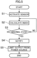
- FIG. 5 is a flowchart of diagnostic processing.
- the controller 71 activates the temperature sensors 2, the differential pressure sensor 3, and the intake air pressure sensor 4 (step S1).
- the controller 71 calculates an index based on the detection values of the temperature sensors 2, the differential pressure sensor 3, and the intake air pressure sensor 4 (step S2).
- the controller 71 detects the filter inlet-side temperature and the filter outlet-side temperature based on the values detected respectively by the temperature sensors 2 (temperature detection step), detects the differential pressure between the filter inlet-side pressure and the filter outlet-side pressure based on the value detected by the differential pressure sensor 3 (differential pressure detection step), detects the intake air pressure of the engine 51 based on the value detected by the intake air pressure sensor 4 (intake air pressure detection step), and calculates an index using these detection results.
- step S3 determines whether the exhaust gas aftertreatment device 10 is in a malfunction state (abnormal state) (step S3: determination step). In a case where a determination is made in step S3 as not being in the abnormal state (S3: NO), the controller 71 returns to step S2. On the other hand, in a case where the determination is made in step S3 as being in the abnormal state (S3: YES), the controller 71 notifies the determination result (step S4). Then, the controller 71 limits the output from the power source within a predetermined range (step S5), and ends this flow.
- the diagnostic device 1 determines a malfunction in the exhaust gas aftertreatment device 10 based on the filter inlet-side temperature, the filter outlet-side temperature, the differential pressure between the filter inlet-side pressure and the filter outlet-side pressure, and the intake air pressure of the engine 51.
- the deposition amount of fine particles deposited on the filter 11 can be obtained from the differential pressure between the filter inlet-side pressure and the filter outlet-side pressure.
- a temperature state of the filter 11 is obtained from the filter inlet-side temperature and the filter outlet-side temperature.
- a malfunction in the exhaust gas aftertreatment device 10 can be detected by using the differential pressure between the filter inlet-side pressure and the filter outlet-side pressure, the filter inlet-side temperature, and the filter outlet-side temperature for the determination.
- the outputs from the temperature sensors 2, the differential pressure sensor 3, and the intake air pressure sensor 4 do not change significantly. Therefore, the malfunction in the exhaust gas aftertreatment device 10 can be detected with high accuracy.
- the controller 71 can determine a malfunction in the exhaust gas aftertreatment device 10 based on the index that is the value obtained by multiplying the ratio between the filter inlet-side temperature and the filter outlet-side temperature by the ratio between the differential pressure between the filter inlet-side pressure and the filter outlet-side pressure and the intake air pressure of the engine 51. Since such an index is dimensionless, a malfunction in the exhaust gas aftertreatment device 10 can be detected with high accuracy by using this index for any type of the work machine 20.
- the determination result in a case where a determination is made that the exhaust gas aftertreatment device 10 has malfunctioned, the determination result can be notified.
- the malfunction in the exhaust gas aftertreatment device 10 can be notified to the operator who operates the work machine 20.
- the malfunction in the exhaust gas aftertreatment device 10 can be notified to a person outside the work machine 20. Therefore, for example, in a case where the work machine 20 is automatically operated, the operation can be stopped by operating the work machine 20.
- the malfunction in the exhaust gas aftertreatment device 10 is transmitted to the terminal device for remotely operating the work machine 20, the malfunction in the exhaust gas aftertreatment device 10 can be notified to the remote operator who performs the remote operation. Therefore, it is possible to prevent the work machine 20 from continuing to operate in a situation where the filter 11 is likely to be damaged by melting.
- the output from the power source in a case where a determination is made that the exhaust gas aftertreatment device 10 has malfunctioned, the output from the power source can be limited within a predetermined range.
- the damage of the filter 11 due to melting can be reduced.
- the regeneration processing of the exhaust gas aftertreatment device 10 in a case where the lower limit value of the output from the power source is limited and the load applied to the engine 51 is increased, the regeneration processing of the exhaust gas aftertreatment device 10 can be assisted.
- the present embodiment it is possible to calculate the accumulated time during which the operation device 28 outputs an operation command in a state where the output from the power source is limited. As a result, a determination is made that the exhaust gas aftertreatment device 10 has malfunctioned, and it can be seen how long the movable portions have been operating in a state where the output from the power source is limited.
- processing relating to information security can be performed on at least one of the values detected respectively by the temperature sensors 2, the differential pressure sensor 3, and the intake air pressure sensor 4.
- modification of a detection value is detected or the detection value is encrypted, thus securing the security of information.
Landscapes
- Engineering & Computer Science (AREA)
- Chemical & Material Sciences (AREA)
- General Engineering & Computer Science (AREA)
- Combustion & Propulsion (AREA)
- Mechanical Engineering (AREA)
- Chemical Kinetics & Catalysis (AREA)
- Computer Security & Cryptography (AREA)
- Theoretical Computer Science (AREA)
- Bioethics (AREA)
- General Health & Medical Sciences (AREA)
- Computer Hardware Design (AREA)
- Software Systems (AREA)
- Physics & Mathematics (AREA)
- General Physics & Mathematics (AREA)
- Health & Medical Sciences (AREA)
- Processes For Solid Components From Exhaust (AREA)
- Combined Controls Of Internal Combustion Engines (AREA)
- Exhaust Gas After Treatment (AREA)
Abstract
Description
- The present invention relates to a diagnostic device for an exhaust gas aftertreatment device, a diagnostic method for an exhaust gas aftertreatment device, and a diagnostic program for an exhaust gas aftertreatment device, the diagnostic device, the diagnostic method, and the diagnostic program diagnosing a malfunction in an exhaust gas aftertreatment device provided in a vehicle.
-
Patent Literature 1 discloses a particulate filter malfunction diagnostic device that determines a malfunction in a particulate filter based on a deposition amount of particulate matter (PM). A PM sensor detects the deposition amount of PM based on a change in electric resistance between a pair of electrodes. - In addition,
Patent Literature 2 discloses a diagnostic device that includes a PM sensor including at least a pair of electrode members forming a capacitor, the PM sensor being provided in a filter member disposed downstream of a diesel particulate filter (DPF), and that determines a malfunction in the DPF based on electrostatic capacitance between the electrode members. - However, with the PM sensor of
Patent Literature 1, a great change in an output is inevitable due to adhesion of PM having a large particle size to a portion between the pair of electrode members. Further, inPatent Literature 2, a capacitor has to be added, and an improvement in DPF is necessary. -
- Patent Literature 1:
JP 2017-48709 A - Patent Literature 2:
JP 2016-70077 A - An object of the present invention is to provide a diagnostic device for an exhaust gas aftertreatment device, a diagnostic method for the exhaust gas aftertreatment device, and a diagnostic program for the exhaust gas aftertreatment device, the diagnostic device, diagnostic method, and diagnostic program being capable of detecting a malfunction in the exhaust gas aftertreatment device with high accuracy.
- Provided is a diagnostic device for an exhaust gas aftertreatment device that has a filter for collecting fine particles from exhaust gas of an engine and is provided in a vehicle, the diagnostic device diagnosing a malfunction in the exhaust gas aftertreatment device, the diagnostic device including: a temperature detection device that detects a filter inlet-side temperature and a filter outlet-side temperature; a differential pressure detection device that detects a differential pressure between a filter inlet-side pressure and a filter outlet-side pressure; an intake air pressure detection device that detects an intake air pressure of the engine; and a controller that determines a malfunction in the exhaust gas aftertreatment device based on values detected by the temperature detection device, the differential pressure detection device, and the intake air pressure detection device.
- Further, provided is a diagnostic method for an exhaust gas aftertreatment device that has a filter for collecting fine particles from exhaust gas of an engine and is provided in a vehicle, the diagnostic method for diagnosing a malfunction in the exhaust gas aftertreatment device, the diagnostic method including: a temperature detection step of detecting a filter inlet-side temperature and a filter outlet-side temperature; a differential pressure detection step of detecting a differential pressure between a filter inlet-side pressure and a filter outlet-side pressure; an intake air pressure detection step of detecting an intake air pressure of the engine; and a determination step of determining a malfunction in the exhaust gas aftertreatment device based on values detected in the temperature detection step, the differential pressure detection step, and the intake air pressure detection step.
- Further, provided is a diagnostic program for an exhaust gas aftertreatment device that has a filter for collecting fine particles from exhaust gas of an engine and is provided in a vehicle, the diagnostic program for causing a computer to diagnose a malfunction in the exhaust gas aftertreatment device, the diagnostic program including causing the computer to determine a malfunction in the exhaust gas aftertreatment device based on a filter inlet-side temperature, a filter outlet-side temperature, a differential pressure between a filter inlet-side pressure and a filter outlet-side pressure, and an intake air pressure of the engine.
- In the present invention, a malfunction in the exhaust gas aftertreatment device is determined based on the filter inlet-side temperature, the filter outlet-side temperature, the differential pressure between the filter inlet-side pressure and the filter outlet-side pressure, and the intake air pressure of the engine. The deposition amount of fine particles deposited on the filter can be obtained from the differential pressure between the filter inlet-side pressure and the filter outlet-side pressure. A temperature state of the filter is obtained from the filter inlet-side temperature and the filter outlet-side temperature. Therefore, before the filter is damaged by melting, a malfunction in the exhaust gas aftertreatment device can be detected by using the differential pressure between the filter inlet-side pressure and the filter outlet-side pressure, the filter inlet-side temperature, and the filter outlet-side temperature for determination. In the present invention, unlike the PM sensor of
Patent Literature 1, the outputs from the temperature detection device, the differential pressure detection device, and the intake air pressure detection device do not change significantly. Therefore, the malfunction in the exhaust gas aftertreatment device can be detected with high accuracy. -
-
FIG. 1 is a side view of a work machine. -
FIG. 2 is a configuration diagram illustrating a hydraulic circuit of the work machine. -
FIG. 3 is a configuration diagram of an exhaust gas aftertreatment device. -
FIG. 4 is a configuration diagram illustrating an electric circuit of the work machine. -
FIG. 5 is a flowchart of diagnostic processing. - A preferred embodiment of the present invention will be described below with reference to the drawings.
- A diagnostic device (diagnostic device 1) for an exhaust gas aftertreatment device according to an embodiment of the present invention diagnoses a malfunction in the exhaust gas aftertreatment device provided in a vehicle. As illustrated in
FIG. 1 which is a side view of awork machine 20, thediagnostic device 1 is provided in thework machine 20. Thework machine 20 is one example of a vehicle, and is, for example, a hydraulic excavator. Thework machine 20 may be operated by an operator in acab 23, may be remotely operated, or may be automatically operated. - The
work machine 20 has a machinemain body 25 including alower travelling body 21 and anupper slewing body 22, anattachment 30, andcylinders 40. - The
lower travelling body 21 is a portion that causes thework machine 20 to travel, and includes, for example, right andleft crawlers 26. Theupper slewing body 22 is slewably attached to an upper part of thelower travelling body 21 via aslewing device 24. Thecab 23 is provided at a front part of theupper slewing body 22. - The
attachment 30 is attached to theupper slewing body 22 to be rotatable in an up-and-down direction. Theattachment 30 includes aboom 31, anarm 32, and abucket 33. Theboom 31 is attached to theupper slewing body 22 to be rotatable in the up-and-down direction (capable of being raised and lowered). Thearm 32 is attached to theboom 31 to be rotatable in the up-and-down direction. Thebucket 33 is attached to thearm 32 to be rotatable in a frontand-rear direction. Thebucket 33 is a tip attachment that is a tip portion of theattachment 30, and is a part that performs work such as excavation, leveling, and scooping of earth and sand. Note that a work object to be held by thebucket 33 is not limited to earth and sand, but may also be stones or waste (such as industrial waste). The tip attachment is not limited to thebucket 33, and may be a grapple, a lifting magnet, or the like. - The
cylinders 40 can hydraulically turn theattachment 30. Thecylinders 40 are hydraulic telescopic cylinders. Thecylinders 40 include aboom cylinder 41, anarm cylinder 42, and abucket cylinder 43. - The
boom cylinder 41 rotates theboom 31 with respect to theupper slewing body 22. Theboom cylinder 41 has a base end portion rotatably attached to theupper slewing body 22. Theboom cylinder 41 has a tip portion rotatably attached to theboom 31. - The
arm cylinder 42 rotates thearm 32 with respect to theboom 31. Thearm cylinder 42 has a base end portion rotatably attached to theboom 31. Thearm cylinder 42 has a tip portion rotatably attached to thearm 32. - The
bucket cylinder 43 rotates thebucket 33 with respect to thearm 32. Thebucket cylinder 43 has a base end portion rotatably attached to thearm 32. Thebucket cylinder 43 has a tip portion rotatably attached to alink member 34 rotatably attached to thebucket 33. - As illustrated in
FIG. 2 which is a configuration diagram illustrating the hydraulic circuit of thework machine 20, thework machine 20 includes anengine 51, ahydraulic pump 52, and acontrol valve group 53. Theengine 51 is a power source of thework machine 20. Thehydraulic pump 52 is driven by theengine 51. Thehydraulic pump 52 includes a lefthydraulic pump 52L and a righthydraulic pump 52R. Thecontrol valve group 53 changes a flow rate of hydraulic oil supplied from thehydraulic pump 52 to thecylinders 40 and the like. Thecontrol valve group 53 includes a leftcontrol valve group 53L and a rightcontrol valve group 53R. - The left
hydraulic pump 52L supplies hydraulic oil to each of a left travelingmotor 54L, a slewingmotor 55, and thearm cylinder 42. The righthydraulic pump 52R supplies hydraulic oil to each of aright traveling motor 54R, theboom cylinder 41, and thebucket cylinder 43. Note thatFIG. 2 illustrates one example of the arrangement of these components, and the arrangement of these components is not limited toFIG. 2 . Theleft traveling motor 54L drives theleft crawler 26 of the lower travellingbody 21, and theright traveling motor 54R drives theright crawler 26 of the lower travellingbody 21. The slewingmotor 55 is provided in theslewing device 24 and slews theupper slewing body 22. - The left
control valve group 53L includes a control valve that changes the flow rate of the hydraulic oil supplied to theleft traveling motor 54L, a control valve that changes the flow rate of the hydraulic oil supplied to the slewingmotor 55, and a control valve that changes the flow rate of the hydraulic oil supplied to thearm cylinder 42. The rightcontrol valve group 53R includes a control valve that changes the flow rate of the hydraulic oil supplied to theright traveling motor 54R, a control valve that changes the flow rate of the hydraulic oil supplied to theboom cylinder 41, and a control valve that changes the flow rate of the hydraulic oil supplied to thebucket cylinder 43. These control valves are controlled by acontroller 71 in response to an operation supplied to an operation device 28 (seeFIG. 1 ) including at least one operation lever provided in thecab 23. Note that in the present embodiment, theoperation device 28 includes a plurality of operation levers, and these operation levers are disposed in thecab 23. - The
engine 51, thehydraulic pump 52, and thecontrol valve group 53 are controlled by thecontroller 71 described later. - As illustrated in
FIG. 1 , the left andright crawlers 26, theupper slewing body 22, and theattachment 30 are movable portions of thework machine 20. Theoperation device 28 outputs operation commands for operating the movable portions. As illustrated inFIG. 2 , theengine 51, thehydraulic pump 52, and thecontrol valve group 53 are power sources that supply power to the movable portions. - As illustrated in
FIG. 3 which is a configuration diagram of the exhaustgas aftertreatment device 10, thework machine 20 includes the exhaustgas aftertreatment device 10. The exhaustgas aftertreatment device 10 is provided in anexhaust pipe 15 through which an exhaust gas of theengine 51 passes, and collects fine particles from the exhaust gas. The exhaustgas aftertreatment device 10 includes afilter 11 that collects fine particles, and anoxidation catalyst 12 that is provided downstream of thefilter 11 and oxidizes unburnt fuel. - The
diagnostic device 1 includes temperature sensors 2 (one example of a temperature detection device), a differential pressure sensor 3 (one example of a differential pressure detection device), and an intake air pressure sensor 4 (one example of an intake air pressure detection device). Thetemperature sensors 2 respectively detect a filter inlet-side temperature and a filter outlet-side temperature. Thedifferential pressure sensor 3 detects a filter inlet-side pressure, a filter outlet-side pressure, and a differential pressure (for example, a differential pressure between an inlet side and an outlet side of the filter 11). The intakeair pressure sensor 4 is provided in anintake air pipe 16 that supplies air to theengine 51, and detects an intake air pressure (boost pressure) of theengine 51. - The filter inlet-side temperature is a temperature detected by the
temperature sensor 2 disposed at an exhaust gas inlet of thefilter 11 or near the inlet. Specifically, the filter inlet-side temperature may be a temperature of the exhaust gas at the inlet of thefilter 11 or the temperature of thefilter 11 at the inlet of thefilter 11. Further, the filter inlet-side temperature may be a temperature of the exhaust gas near the inlet upstream of the inlet of thefilter 11 or a temperature of the pipe near the inlet upstream of the inlet of thefilter 11. - The filter outlet-side temperature is a temperature detected by the
temperature sensor 2 disposed at the exhaust gas outlet of thefilter 11 or near the outlet. Specifically, the filter outlet-side temperature may be a temperature of the exhaust gas at the outlet of thefilter 11 or a temperature of thefilter 11 at the outlet of thefilter 11. Further, the filter outlet-side temperature may be a temperature of the exhaust gas near the outlet downstream of the outlet of thefilter 11, or may be a temperature of the pipe near the outlet downstream of the outlet of thefilter 11. - The filter inlet-side pressure may be a pressure at the inlet of the
filter 11, or may be a pressure near the inlet upstream of the inlet of thefilter 11. The filter outlet-side pressure may be a pressure at the outlet of thefilter 11, or may be a pressure near the outlet downstream of the outlet of thefilter 11. Each of "upstream" and "downstream" is based on the flow direction of the exhaust gas. - As illustrated in
FIG. 4 which is a configuration diagram of an electric circuit of thework machine 20, thework machine 20 includes thecontroller 71, astorage device 73, and acommunication device 74. - The
controller 71 includes a computer that inputs and outputs signals, performs arithmetic (processing), stores information, and the like. For example, thecontroller 71 includes determination means, notification means, limiting means, accumulated time calculation means, and security processing means, described later. Functions of the determination means, the notification means, the limiting means, the accumulated time calculation means, and the security processing means in thecontroller 71 are implemented by executing programs stored in the storage unit (not illustrated) of thecontroller 71. Thecontroller 71 may be provided at only one place or may be provided separately at a plurality of places. Thecontroller 71 may be mounted on thework machine 20 or may be disposed in a server or the like outside thework machine 20. Thediagnostic device 1 includes thecontroller 71. - The
controller 71 receives the temperature values respectively detected by thetemperature sensors 2. Thecontroller 71 handles, for example, a temperature value expressed as an absolute temperature. Further, thecontroller 71 receives a differential pressure value detected by thedifferential pressure sensor 3. Further, thecontroller 71 receives a pressure value detected by the intakeair pressure sensor 4. Thecontroller 71 periodically acquires the temperature values respectively detected by thetemperature sensors 2, the differential pressure value detected by thedifferential pressure sensor 3, and the pressure value detected by the intakeair pressure sensor 4. - Further, the
controller 71 receives an operation command from theoperation device 28. - The
communication device 74 can transmit and receive data by performing communication such as wireless communication or wired communication with a server or the like outside thework machine 20. - The controller 71 (specifically, the determination means) determines a malfunction in the exhaust
gas aftertreatment device 10 based on the values detected respectively by thetemperature sensors 2, thedifferential pressure sensor 3, and the intakeair pressure sensor 4. Specifically, for example, thecontroller 71 may determine a malfunction in the exhaustgas aftertreatment device 10 based on an index. The index may be a value based on a ratio between the filter inlet-side temperature and the filter outlet-side temperature and a ratio between the differential pressure (differential pressure between the filter inlet-side pressure and the filter outlet-side pressure) and the intake air pressure of theengine 51. Thecontroller 71 may determine that the exhaustgas aftertreatment device 10 has malfunctioned when the index exceeds a threshold. - More specifically, in a case where a value obtained by dividing the filter outlet-side temperature by the filter inlet-side temperature is represented by "a", and a value obtained by dividing the differential pressure between the filter inlet-side pressure and the filter outlet-side pressure by the intake air pressure of the
engine 51 is represented by "b", the index may be a value represented by "a/b". - In a case where the
filter 11 is clogged, the ratio of the differential pressure to the intake air pressure of theengine 51 in the exhaustgas aftertreatment device 10 is greater than the ratio in the normal state, and the value of "b" is greater. The case where thefilter 11 is clogged is a state where a large amount of fine particles are deposited on thefilter 11, and burning the fine particles in this state may cause a damage of thefilter 11 due to melting. On the other hand, when the value of "b" increases, the index "a/b" falls below a lower limit value (threshold) in the normal state. Therefore, before thefilter 11 is damaged by melting, thecontroller 71 can detect a malfunction in the exhaustgas aftertreatment device 10 by detecting that the index falls below the lower limit value. - The higher the temperature of the
filter 11, the greater the value of "a", which is the ratio between the filter inlet-side temperature and the filter outlet-side temperature. In a case where the temperature of thefilter 11 becomes high, a damage of thefilter 11 due to melting might occur. On the other hand, when the value of "a" increases, the index "a/b" exceeds an upper limit value (threshold) in the normal state. Therefore, before thefilter 11 is damaged by melting, thecontroller 71 can detect a malfunction in the exhaustgas aftertreatment device 10 by detecting that the index exceeds an upper limit value. - Note that the index may be obtained by multiplying "a/b" by a coefficient learned from past data. For example, the index may be obtained by multiplying a numerical value of "g(a/b)" including "a/b" by a coefficient f(t) that changes with time t. Specifically, for example, "f(t) = t" and "g(a/b) = (a/b)2" may be allowable, and in this case, the index increases with the lapse of time.
- Note that the values of "a" and "b" in the index may be weighted. For example, the value of "a" may be set to have a greater weight than the value of "b". Further, the index may be a product "a × b" obtained from "a" and "b". In this case, the upper limit value (threshold) of the index in the normal state is set in consideration of a fact that the value of "b" increases when the
filter 11 is clogged and the value of "a" increases when thefilter 11 has a high temperature. Before thefilter 11 is damaged by melting, thecontroller 71 can detect a malfunction in the exhaustgas aftertreatment device 10 by detecting that the index exceeds the upper limit value (threshold). - As described above, a malfunction in the exhaust
gas aftertreatment device 10 is determined based on the filter inlet-side temperature, the filter outlet-side temperature, the differential pressure between the filter inlet-side pressure and the filter outlet-side pressure, and the intake air pressure of theengine 51. The deposition amount of fine particles deposited on thefilter 11 can be obtained from the differential pressure between the filter inlet-side pressure and the filter outlet-side pressure. A temperature state of thefilter 11 is obtained from the filter inlet-side temperature and the filter outlet-side temperature. Therefore, before thefilter 11 is damaged by melting, a malfunction in the exhaustgas aftertreatment device 10 can be detected by using the differential pressure between the filter inlet-side pressure and the filter outlet-side pressure, the filter inlet-side temperature, and the filter outlet-side temperature for the determination. In the present embodiment, unlike the PM sensor ofPatent Literature 1, the outputs from thetemperature sensors 2, thedifferential pressure sensor 3, and the intakeair pressure sensor 4 do not change significantly. Therefore, the malfunction in the exhaustgas aftertreatment device 10 can be detected with high accuracy. - Further, in the present embodiment, a malfunction in the exhaust
gas aftertreatment device 10 is determined based on the index that is the value obtained by multiplying the ratio between the filter inlet-side temperature and the filter outlet-side temperature by a ratio between the differential pressure between the filter inlet-side pressure and the filter outlet-side pressure and the intake air pressure of theengine 51. Since such an index is dimensionless, a malfunction in the exhaustgas aftertreatment device 10 can be detected with high accuracy by using this index for any type of thework machine 20. - The controller 71 (specifically, the notification means) may perform control for notifying a determination result in a case where the controller 71 (specifically, the determination means) determines that the exhaust
gas aftertreatment device 10 has malfunctioned. Specifically, for example, in a case where thework machine 20 includes a notification device, in thework machine 20, when the notification device notifies the determination result, a malfunction in the exhaustgas aftertreatment device 10 is notified to the operator who operates thework machine 20. The notification device may be, for example, a speaker or a display provided in thecab 23 of thework machine 20. In addition, thecontroller 71 may transmit a fact that the exhaustgas aftertreatment device 10 has malfunctioned to an external device such as a server located outside thework machine 20, via thecommunication device 74. In this case, a malfunction in the exhaustgas aftertreatment device 10 can be notified to a person outside thework machine 20. Therefore, for example, in a case where thework machine 20 is automatically operated, the operation can be stopped by operating thework machine 20. Further, thecontroller 71 may transmit the fact that the exhaustgas aftertreatment device 10 has malfunctioned to a terminal device for remotely operating thework machine 20. In this case, the malfunction in the exhaustgas aftertreatment device 10 can be notified to a remote operator who performs a remote operation. As described above, it is possible to prevent thework machine 20 from continuing to operate in a situation where thefilter 11 is likely to be damaged by melting. - Further, the controller 71 (specifically, the limiting means) may perform control for limiting the output from the power source within a predetermined range in a case where the controller 71 (specifically, the determination means) determines that the exhaust
gas aftertreatment device 10 has malfunctioned. Specifically, thecontroller 71 limits an output from at least one of theengine 51, thehydraulic pump 52, and thecontrol valve group 53 within the predetermined range. - When the upper limit value of the output from the power source is limited, the damage of the
filter 11 due to melting can be reduced. In addition, in a case where the lower limit value of the output from the power source is limited and the load applied to theengine 51 is increased, the regeneration processing of the exhaustgas aftertreatment device 10 can be assisted. The regeneration processing is processing for increasing the load on theengine 51 and heating thefilter 11 to burn the fine particles deposited on thefilter 11. - Further, the controller 71 (specifically, the accumulated time calculation means) may calculate an accumulated time during which the
operation device 28 outputs an operation command in a state where the controller 71 (specifically, the limiting means) limits the output from the power source. Thecontroller 71 stores the accumulated time in thestorage device 73. As a result, a determination is made that the exhaustgas aftertreatment device 10 has malfunctioned, and it can be seen how long the movable portions have been operating in a state where the output from the power source is limited. Thecontroller 71 then transmits the accumulated time stored in thestorage device 73 from thecommunication device 74 to the outside, for example, at timing when theengine 51 is stopped. - The controller 71 (specifically, the security processing means) performs processing relating to information security on at least one of the values detected by the
temperature sensors 2, thedifferential pressure sensor 3, and the intakeair pressure sensor 4. Specifically, at least one of thetemperature sensors 2, thedifferential pressure sensor 3, and the intakeair pressure sensor 4 gives a signature to the detection value to be transmitted to thecontroller 71. Thecontroller 71 verifies the signature, and in a case where the verification succeeds, calculates an index based on the detection value to which the signature is given. When verifying the signature given to the detection value transmitted to thecontroller 71, thecontroller 71 can detect modification of the detection value, and can check a transmission source to prevent spoof. Accordingly, the security of the detection value can be ensured. Note that an external device such as a server outside thework machine 20 may verify the signature. In addition, thecontroller 71 itself is desirably mounted in a region having tamper resistance. For example, it is desirable that thecontroller 71 is stored in a housing so as to be hardly removed in an unauthorized manner, or to enable detection of unauthorized removal of thecontroller 71 from the housing. - Note that at least one of the
temperature sensors 2, thedifferential pressure sensor 3, and the intakeair pressure sensor 4 may encrypt the detection value to be transmitted to thecontroller 71. The encryption may be public key encryption or common key encryption. Thecontroller 71 decrypts the encrypted detection value, and calculates an index based on the decrypted detection value when the decryption succeeds. When thecontroller 71 decrypts the encrypted detection value transmitted to thecontroller 71, high confidentiality can be maintained. Accordingly, the security of the detection value can be ensured. Note that an external device such as a server outside thework machine 20 may decrypt the detection value. Further, thecontroller 71 desirably stores the encrypted detection value in an area having tamper resistance (a chip or the like having tamper resistance against unauthorized access). - Next, the operation of the
diagnostic device 1 will be described with reference toFIG. 5 which is a flowchart of diagnostic processing. - First, the
controller 71 activates thetemperature sensors 2, thedifferential pressure sensor 3, and the intake air pressure sensor 4 (step S1). Next, thecontroller 71 calculates an index based on the detection values of thetemperature sensors 2, thedifferential pressure sensor 3, and the intake air pressure sensor 4 (step S2). Specifically, thecontroller 71 detects the filter inlet-side temperature and the filter outlet-side temperature based on the values detected respectively by the temperature sensors 2 (temperature detection step), detects the differential pressure between the filter inlet-side pressure and the filter outlet-side pressure based on the value detected by the differential pressure sensor 3 (differential pressure detection step), detects the intake air pressure of theengine 51 based on the value detected by the intake air pressure sensor 4 (intake air pressure detection step), and calculates an index using these detection results. - Next, the
controller 71 determines whether the exhaustgas aftertreatment device 10 is in a malfunction state (abnormal state) (step S3: determination step). In a case where a determination is made in step S3 as not being in the abnormal state (S3: NO), thecontroller 71 returns to step S2. On the other hand, in a case where the determination is made in step S3 as being in the abnormal state (S3: YES), thecontroller 71 notifies the determination result (step S4). Then, thecontroller 71 limits the output from the power source within a predetermined range (step S5), and ends this flow. - As described above, the
diagnostic device 1 according to the present embodiment determines a malfunction in the exhaustgas aftertreatment device 10 based on the filter inlet-side temperature, the filter outlet-side temperature, the differential pressure between the filter inlet-side pressure and the filter outlet-side pressure, and the intake air pressure of theengine 51. The deposition amount of fine particles deposited on thefilter 11 can be obtained from the differential pressure between the filter inlet-side pressure and the filter outlet-side pressure. A temperature state of thefilter 11 is obtained from the filter inlet-side temperature and the filter outlet-side temperature. Therefore, before thefilter 11 is damaged by melting, a malfunction in the exhaustgas aftertreatment device 10 can be detected by using the differential pressure between the filter inlet-side pressure and the filter outlet-side pressure, the filter inlet-side temperature, and the filter outlet-side temperature for the determination. In thediagnostic device 1 according to the present embodiment, unlike the PM sensor ofPatent Literature 1, the outputs from thetemperature sensors 2, thedifferential pressure sensor 3, and the intakeair pressure sensor 4 do not change significantly. Therefore, the malfunction in the exhaustgas aftertreatment device 10 can be detected with high accuracy. - Further, in the present embodiment, the
controller 71 can determine a malfunction in the exhaustgas aftertreatment device 10 based on the index that is the value obtained by multiplying the ratio between the filter inlet-side temperature and the filter outlet-side temperature by the ratio between the differential pressure between the filter inlet-side pressure and the filter outlet-side pressure and the intake air pressure of theengine 51. Since such an index is dimensionless, a malfunction in the exhaustgas aftertreatment device 10 can be detected with high accuracy by using this index for any type of thework machine 20. - Further, in the present embodiment, in a case where a determination is made that the exhaust
gas aftertreatment device 10 has malfunctioned, the determination result can be notified. For example, in a case where the determination result is notified in thework machine 20, the malfunction in the exhaustgas aftertreatment device 10 can be notified to the operator who operates thework machine 20. Further, in a case where the determination result is notified to the outside of thework machine 20 via thecommunication device 74, the malfunction in the exhaustgas aftertreatment device 10 can be notified to a person outside thework machine 20. Therefore, for example, in a case where thework machine 20 is automatically operated, the operation can be stopped by operating thework machine 20. In a case where the malfunction in the exhaustgas aftertreatment device 10 is transmitted to the terminal device for remotely operating thework machine 20, the malfunction in the exhaustgas aftertreatment device 10 can be notified to the remote operator who performs the remote operation. Therefore, it is possible to prevent thework machine 20 from continuing to operate in a situation where thefilter 11 is likely to be damaged by melting. - Further, in the present embodiment, in a case where a determination is made that the exhaust
gas aftertreatment device 10 has malfunctioned, the output from the power source can be limited within a predetermined range. When the upper limit value of the output from the power source is limited, the damage of thefilter 11 due to melting can be reduced. In addition, in a case where the lower limit value of the output from the power source is limited and the load applied to theengine 51 is increased, the regeneration processing of the exhaustgas aftertreatment device 10 can be assisted. - Further, in the present embodiment, it is possible to calculate the accumulated time during which the
operation device 28 outputs an operation command in a state where the output from the power source is limited. As a result, a determination is made that the exhaustgas aftertreatment device 10 has malfunctioned, and it can be seen how long the movable portions have been operating in a state where the output from the power source is limited. - Further, in the present embodiment, processing relating to information security can be performed on at least one of the values detected respectively by the
temperature sensors 2, thedifferential pressure sensor 3, and the intakeair pressure sensor 4. As a result, for example, modification of a detection value is detected or the detection value is encrypted, thus securing the security of information. - Although the embodiment of the present invention has been described above, only specific example has been described, and the present invention is not particularly limited to the embodiment, and a specific configuration and the like can be modified in design as appropriate. In addition, the actions and effects described in the embodiment of the present invention merely recite the most suitable actions and effects resulting from the present invention, and the actions and effects according to the present invention are not limited to those described in the embodiment of the present invention.
Claims (8)
- diagnostic device for an exhaust gas aftertreatment device that has a filter for collecting fine particles from exhaust gas of an engine and is provided in a vehicle, the diagnostic device diagnosing a malfunction in the exhaust gas aftertreatment device, the diagnostic device comprising:a temperature detection device that detects a filter inlet-side temperature and a filter outlet-side temperature;a differential pressure detection device that detects a differential pressure between a filter inlet-side pressure and a filter outlet-side pressure;an intake air pressure detection device that detects an intake air pressure of the engine; anda controller that determines a malfunction in the exhaust gas aftertreatment device based on values detected by the temperature detection device, the differential pressure detection device, and the intake air pressure detection device.
- The diagnostic device for the exhaust gas aftertreatment device according to claim 1, whereinthe controller determines a malfunction in the exhaust gas aftertreatment device based on an index, andthe index is a value based on a ratio between the filter inlet-side temperature and the filter outlet-side temperature and a ratio between the differential pressure and the intake air pressure of the engine.
- The diagnostic device for the exhaust gas aftertreatment device according to claim 1 or 2, wherein the controller performs control for notifying a determination result in a case where the controller determines that the exhaust gas aftertreatment device has malfunctioned.
- The diagnostic device for the exhaust gas aftertreatment device according to any one of claims 1 to 3, whereinthe vehicle is a work machine,the work machine includesa plurality of movable portions, anda power source that supplies power to the plurality of movable portions, andthe controller performs control for limiting an output from the power source within a predetermined range in a case where the controller determines that the exhaust gas aftertreatment device has malfunctioned.
- The diagnostic device for the exhaust gas aftertreatment device according to claim 4, further comprising an operation device that outputs operation commands for operating the movable portions,
wherein the controller calculates an accumulated time during which the operation device outputs the operation commands in a state where the output from the power source is limited. - The diagnostic device for the exhaust gas aftertreatment device according to any one of claims 1 to 5, wherein the controller performs processing relating to information security on at least one of the values detected respectively by the temperature detection device, the differential pressure detection device, and the intake air pressure detection device.
- diagnostic method for an exhaust gas aftertreatment device that has a filter for collecting fine particles from exhaust gas of an engine and is provided in a vehicle, the diagnostic method for diagnosing a malfunction in the exhaust gas aftertreatment device, the diagnostic method comprising:a temperature detection step of detecting a filter inlet-side temperature and a filter outlet-side temperature;a differential pressure detection step of detecting a differential pressure between a filter inlet-side pressure and a filter outlet-side pressure;an intake air pressure detection step of detecting an intake air pressure of the engine; anda determination step of determining a malfunction in the exhaust gas aftertreatment device based on values detected in the temperature detection step, the differential pressure detection step, and the intake air pressure detection step.
- diagnostic program for an exhaust gas aftertreatment device that has a filter for collecting fine particles from exhaust gas of an engine and is provided in a vehicle, the diagnostic program for causing a computer to diagnose a malfunction in the exhaust gas aftertreatment device, the diagnostic program comprising
causing the computer to determine a malfunction in the exhaust gas aftertreatment device based on a filter inlet-side temperature, a filter outlet-side temperature, a differential pressure between a filter inlet-side pressure and a filter outlet-side pressure, and an intake air pressure of the engine.
Applications Claiming Priority (2)
| Application Number | Priority Date | Filing Date | Title |
|---|---|---|---|
| JP2022014996A JP7750129B2 (en) | 2022-02-02 | 2022-02-02 | Diagnostic device for exhaust gas aftertreatment device, diagnostic method for exhaust gas aftertreatment device, and diagnostic program for exhaust gas aftertreatment device |
| PCT/JP2023/002124 WO2023149285A1 (en) | 2022-02-02 | 2023-01-24 | Diagnostic device for exhaust gas aftertreatment device, diagnostic method for exhaust gas aftertreatment device, and diagnostic program for exhaust gas aftertreatment device |
Publications (2)
| Publication Number | Publication Date |
|---|---|
| EP4455462A1 true EP4455462A1 (en) | 2024-10-30 |
| EP4455462A4 EP4455462A4 (en) | 2024-11-20 |
Family
ID=87552225
Family Applications (1)
| Application Number | Title | Priority Date | Filing Date |
|---|---|---|---|
| EP23749601.3A Pending EP4455462A4 (en) | 2022-02-02 | 2023-01-24 | DIAGNOSTIC DEVICE FOR EXHAUST GAS AFTERTREATMENT DEVICE, DIAGNOSTIC METHOD FOR EXHAUST GAS AFTERTREATMENT DEVICE, AND DIAGNOSTIC PROGRAM FOR EXHAUST GAS AFTERTREATMENT DEVICE |
Country Status (5)
| Country | Link |
|---|---|
| US (1) | US12404816B2 (en) |
| EP (1) | EP4455462A4 (en) |
| JP (1) | JP7750129B2 (en) |
| CN (1) | CN118613643A (en) |
| WO (1) | WO2023149285A1 (en) |
Families Citing this family (1)
| Publication number | Priority date | Publication date | Assignee | Title |
|---|---|---|---|---|
| CN118934194B (en) * | 2024-08-29 | 2025-04-29 | 北京晟宇数智生态科技有限公司 | Method for detecting cheating behavior in exhaust gas testing for temporarily installed three-way catalytic converters |
Family Cites Families (14)
| Publication number | Priority date | Publication date | Assignee | Title |
|---|---|---|---|---|
| JP4762043B2 (en) | 2006-04-27 | 2011-08-31 | 本田技研工業株式会社 | Particulate filter state detection device |
| JP4506724B2 (en) * | 2006-06-07 | 2010-07-21 | トヨタ自動車株式会社 | PM trapper failure detection system |
| JP5001778B2 (en) * | 2007-10-04 | 2012-08-15 | 日立建機株式会社 | Diesel engine exhaust gas purification system |
| JP2013104416A (en) * | 2011-11-16 | 2013-05-30 | Mitsubishi Heavy Ind Ltd | Device for estimating pm accumulation quantity in dpf |
| US9151015B2 (en) * | 2012-01-13 | 2015-10-06 | Hitachi Construction Machinery Co., Ltd. | Construction machine |
| JP2013148045A (en) * | 2012-01-20 | 2013-08-01 | Mitsubishi Heavy Ind Ltd | Exhaust emission control system of engine |
| JP2015148182A (en) * | 2014-02-06 | 2015-08-20 | 日立建機株式会社 | Construction machine |
| JP2016070077A (en) | 2014-09-26 | 2016-05-09 | いすゞ自動車株式会社 | Diagnostic equipment |
| JP6319034B2 (en) * | 2014-10-10 | 2018-05-09 | トヨタ自動車株式会社 | Filter inspection device and filter inspection method |
| JP6358191B2 (en) * | 2015-08-17 | 2018-07-18 | トヨタ自動車株式会社 | Control device for internal combustion engine |
| JP6585970B2 (en) | 2015-09-01 | 2019-10-02 | 日野自動車株式会社 | Particulate filter failure diagnosis device |
| DE102016103498A1 (en) | 2016-02-26 | 2017-08-31 | Infineon Technologies Ag | A method of communicating data from a sensor device to an electronic control unit, a sensor device, and an electronic control unit |
| WO2018062363A1 (en) | 2016-09-29 | 2018-04-05 | 住友建機株式会社 | Shovel |
| JP6618494B2 (en) * | 2017-03-01 | 2019-12-11 | 株式会社日立建機ティエラ | Construction machinery |
-
2022
- 2022-02-02 JP JP2022014996A patent/JP7750129B2/en active Active
-
2023
- 2023-01-24 EP EP23749601.3A patent/EP4455462A4/en active Pending
- 2023-01-24 US US18/833,443 patent/US12404816B2/en active Active
- 2023-01-24 CN CN202380019258.3A patent/CN118613643A/en active Pending
- 2023-01-24 WO PCT/JP2023/002124 patent/WO2023149285A1/en not_active Ceased
Also Published As
| Publication number | Publication date |
|---|---|
| CN118613643A (en) | 2024-09-06 |
| WO2023149285A1 (en) | 2023-08-10 |
| JP7750129B2 (en) | 2025-10-07 |
| JP2023112953A (en) | 2023-08-15 |
| US20250109714A1 (en) | 2025-04-03 |
| EP4455462A4 (en) | 2024-11-20 |
| US12404816B2 (en) | 2025-09-02 |
Similar Documents
| Publication | Publication Date | Title |
|---|---|---|
| CN104066940B (en) | construction machinery | |
| US7333922B2 (en) | System and method of monitoring machine performance | |
| CN105026214B (en) | Abnormal information control device for construction machinery | |
| JP5841612B2 (en) | Construction machine operation data collection device | |
| CN106605054B (en) | Construction Machinery Management System | |
| CN104040126B (en) | Construction machine | |
| JP2014186631A (en) | Diagnosis processing system, terminal equipment and server | |
| US12404816B2 (en) | Diagnostic device for exhaust gas aftertreatment device, diagnostic method for exhaust gas aftertreatment device, and diagnostic program for exhaust gas aftertreatment device | |
| CN102086796A (en) | Hydraulic working rig | |
| CN105027015A (en) | Construction machine maintenance device | |
| JP6872506B2 (en) | Construction machinery | |
| JP4315346B2 (en) | Engine diagnostic equipment for construction machinery | |
| JP2005180226A (en) | Engine air supply system abnormality detection device and abnormality detection method for construction machinery | |
| KR102116915B1 (en) | Construction machinery | |
| US12523168B2 (en) | Working machine, degradation detection device for oxidation catalyst, degradation detection method for oxidation catalyst, and degradation detection program for oxidation catalyst | |
| JP2015148182A (en) | Construction machine | |
| JP2011017258A (en) | Construction vehicle | |
| JP2022053252A (en) | Construction machine | |
| JP7838211B2 (en) | Shovel, shovel control device | |
| CN121079468A (en) | Method for monitoring excavation operations |
Legal Events
| Date | Code | Title | Description |
|---|---|---|---|
| STAA | Information on the status of an ep patent application or granted ep patent |
Free format text: STATUS: THE INTERNATIONAL PUBLICATION HAS BEEN MADE |
|
| PUAI | Public reference made under article 153(3) epc to a published international application that has entered the european phase |
Free format text: ORIGINAL CODE: 0009012 |
|
| STAA | Information on the status of an ep patent application or granted ep patent |
Free format text: STATUS: REQUEST FOR EXAMINATION WAS MADE |
|
| 17P | Request for examination filed |
Effective date: 20240723 |
|
| AK | Designated contracting states |
Kind code of ref document: A1 Designated state(s): AL AT BE BG CH CY CZ DE DK EE ES FI FR GB GR HR HU IE IS IT LI LT LU LV MC ME MK MT NL NO PL PT RO RS SE SI SK SM TR |
|
| A4 | Supplementary search report drawn up and despatched |
Effective date: 20241023 |
|
| RIC1 | Information provided on ipc code assigned before grant |
Ipc: F01N 11/00 20060101ALI20241017BHEP Ipc: F01N 3/021 20060101ALI20241017BHEP Ipc: G06F 21/64 20130101ALI20241017BHEP Ipc: F02D 45/00 20060101ALI20241017BHEP Ipc: F01N 3/023 20060101ALI20241017BHEP Ipc: F01N 3/00 20060101AFI20241017BHEP |
|
| STAA | Information on the status of an ep patent application or granted ep patent |
Free format text: STATUS: EXAMINATION IS IN PROGRESS |
|
| DAV | Request for validation of the european patent (deleted) | ||
| DAX | Request for extension of the european patent (deleted) | ||
| 17Q | First examination report despatched |
Effective date: 20250425 |