EP4455457A1 - Retainer tool and method for disassembling an aircraft engine - Google Patents
Retainer tool and method for disassembling an aircraft engine Download PDFInfo
- Publication number
- EP4455457A1 EP4455457A1 EP24173183.5A EP24173183A EP4455457A1 EP 4455457 A1 EP4455457 A1 EP 4455457A1 EP 24173183 A EP24173183 A EP 24173183A EP 4455457 A1 EP4455457 A1 EP 4455457A1
- Authority
- EP
- European Patent Office
- Prior art keywords
- compressor case
- case
- pin
- compressor
- base
- Prior art date
- Legal status (The legal status is an assumption and is not a legal conclusion. Google has not performed a legal analysis and makes no representation as to the accuracy of the status listed.)
- Pending
Links
Images



Classifications
-
- F—MECHANICAL ENGINEERING; LIGHTING; HEATING; WEAPONS; BLASTING
- F01—MACHINES OR ENGINES IN GENERAL; ENGINE PLANTS IN GENERAL; STEAM ENGINES
- F01D—NON-POSITIVE DISPLACEMENT MACHINES OR ENGINES, e.g. STEAM TURBINES
- F01D5/00—Blades; Blade-carrying members; Heating, heat-insulating, cooling or antivibration means on the blades or the members
- F01D5/005—Repairing methods or devices
-
- F—MECHANICAL ENGINEERING; LIGHTING; HEATING; WEAPONS; BLASTING
- F02—COMBUSTION ENGINES; HOT-GAS OR COMBUSTION-PRODUCT ENGINE PLANTS
- F02C—GAS-TURBINE PLANTS; AIR INTAKES FOR JET-PROPULSION PLANTS; CONTROLLING FUEL SUPPLY IN AIR-BREATHING JET-PROPULSION PLANTS
- F02C7/00—Features, components parts, details or accessories, not provided for in, or of interest apart form groups F02C1/00 - F02C6/00; Air intakes for jet-propulsion plants
-
- F—MECHANICAL ENGINEERING; LIGHTING; HEATING; WEAPONS; BLASTING
- F01—MACHINES OR ENGINES IN GENERAL; ENGINE PLANTS IN GENERAL; STEAM ENGINES
- F01D—NON-POSITIVE DISPLACEMENT MACHINES OR ENGINES, e.g. STEAM TURBINES
- F01D11/00—Preventing or minimising internal leakage of working-fluid, e.g. between stages
- F01D11/003—Preventing or minimising internal leakage of working-fluid, e.g. between stages by packing rings; Mechanical seals
-
- F—MECHANICAL ENGINEERING; LIGHTING; HEATING; WEAPONS; BLASTING
- F01—MACHINES OR ENGINES IN GENERAL; ENGINE PLANTS IN GENERAL; STEAM ENGINES
- F01D—NON-POSITIVE DISPLACEMENT MACHINES OR ENGINES, e.g. STEAM TURBINES
- F01D25/00—Component parts, details, or accessories, not provided for in, or of interest apart from, other groups
- F01D25/24—Casings; Casing parts, e.g. diaphragms, casing fastenings
- F01D25/243—Flange connections; Bolting arrangements
-
- F—MECHANICAL ENGINEERING; LIGHTING; HEATING; WEAPONS; BLASTING
- F02—COMBUSTION ENGINES; HOT-GAS OR COMBUSTION-PRODUCT ENGINE PLANTS
- F02C—GAS-TURBINE PLANTS; AIR INTAKES FOR JET-PROPULSION PLANTS; CONTROLLING FUEL SUPPLY IN AIR-BREATHING JET-PROPULSION PLANTS
- F02C3/00—Gas-turbine plants characterised by the use of combustion products as the working fluid
- F02C3/04—Gas-turbine plants characterised by the use of combustion products as the working fluid having a turbine driving a compressor
-
- F—MECHANICAL ENGINEERING; LIGHTING; HEATING; WEAPONS; BLASTING
- F04—POSITIVE - DISPLACEMENT MACHINES FOR LIQUIDS; PUMPS FOR LIQUIDS OR ELASTIC FLUIDS
- F04D—NON-POSITIVE-DISPLACEMENT PUMPS
- F04D29/00—Details, component parts, or accessories
- F04D29/60—Mounting; Assembling; Disassembling
- F04D29/64—Mounting; Assembling; Disassembling of axial pumps
- F04D29/644—Mounting; Assembling; Disassembling of axial pumps especially adapted for elastic fluid pumps
-
- F—MECHANICAL ENGINEERING; LIGHTING; HEATING; WEAPONS; BLASTING
- F05—INDEXING SCHEMES RELATING TO ENGINES OR PUMPS IN VARIOUS SUBCLASSES OF CLASSES F01-F04
- F05D—INDEXING SCHEME FOR ASPECTS RELATING TO NON-POSITIVE-DISPLACEMENT MACHINES OR ENGINES, GAS-TURBINES OR JET-PROPULSION PLANTS
- F05D2230/00—Manufacture
- F05D2230/70—Disassembly methods
-
- F—MECHANICAL ENGINEERING; LIGHTING; HEATING; WEAPONS; BLASTING
- F05—INDEXING SCHEMES RELATING TO ENGINES OR PUMPS IN VARIOUS SUBCLASSES OF CLASSES F01-F04
- F05D—INDEXING SCHEME FOR ASPECTS RELATING TO NON-POSITIVE-DISPLACEMENT MACHINES OR ENGINES, GAS-TURBINES OR JET-PROPULSION PLANTS
- F05D2230/00—Manufacture
- F05D2230/72—Maintenance
-
- F—MECHANICAL ENGINEERING; LIGHTING; HEATING; WEAPONS; BLASTING
- F05—INDEXING SCHEMES RELATING TO ENGINES OR PUMPS IN VARIOUS SUBCLASSES OF CLASSES F01-F04
- F05D—INDEXING SCHEME FOR ASPECTS RELATING TO NON-POSITIVE-DISPLACEMENT MACHINES OR ENGINES, GAS-TURBINES OR JET-PROPULSION PLANTS
- F05D2260/00—Function
- F05D2260/30—Retaining components in desired mutual position
Definitions
- the application relates generally to aircraft engines and, more particularly, to systems and methods used to disassemble parts of such aircraft engines.
- Some gas turbine engines have a plurality of engine cases fastened together via flanges. In some situations, it may be required to disassemble the engine cases to replace and/or repair parts. However, in some configurations, a disassembly process may be impeded by other components of the gas turbine engine. Improvements are therefore sought.
- an assembly comprising: a gas turbine engine including: a compressor including a rotor including blades rotatable about a central axis and disposed in a gas path of the gas turbine engine, a stator including one or more vanes disposed in the gas path, and a compressor case disposed around the stator; a combustor downstream of the compressor along the gas path; and a combustor case surrounding the combustor and secured to the compressor case; and a retainer for interlocking the stator with the compressor case when disassembling the combustor case from the compressor case, the retainer including: a base secured to the compressor case; and a pin extending from the base and radially inwardly through the compressor case via an aperture defined in the compressor case, the pin engaging with the stator to prevent axial movement of the stator relative to the compressor case.
- the assembly described above may include any of the following features, in any combinations.
- the pin is received into an opening defined in the stator, the pin abutting a peripheral wall of the opening.
- a transverse cross-sectional profile of the pin matches a shape of the opening of the stator.
- the opening of the stator and the aperture of the compressor case are at least partially in register with one another.
- the pin is received through the opening via a movement along a radial direction of the pin relative to the central axis.
- the base includes a first locating surface and the compressor case includes a second locating surface engaged with the first locating surface to axially interlock the base with the compressor case.
- the first locating surface is a first peripheral face defined by the base and the second locating surface is a second peripheral face circumscribing the aperture.
- the base includes a peripheral flange protruding outwardly from the first peripheral face, the peripheral flange in abutment against the compressor case when the pin is received through an opening defined through the stator.
- the peripheral flange defines a hole in register with a threaded aperture defined by the compressor case, a fastener extending through the hole and threaded to the threaded aperture.
- the base is securable to the compressor case in a single relative orientation of the retainer relative to the compressor case.
- the compressor case includes a first flange and the combustor case includes a second flange securable to the first flange, a seal sandwiched between the first flange and the second flange.
- the aperture is one of a plurality of apertures circumferentially distributed about the central axis
- the retainer is one of a plurality of retainers each having a respective pin received within a respective one of the plurality of apertures.
- a method of disassembling a combustor case from a compressor case of a gas turbine engine, the compressor case surrounding a stator assembly comprising: receiving a retainer tool having a base and a pin secured to the base; locking the stator assembly to the compressor case using the retainer tool by inserting the pin through an aperture defined by the compressor case until the pin engages the stator assembly and by securing the base to the compressor case; and disassembling the combustor case from the compressor case when the stator assembly is locked to the compressor case with the retainer tool.
- the method described above may include any of the following features, in any combinations.
- the locking of the stator assembly to the compressor case includes inserting the pin through an opening of the stator assembly and abutting the pin against a peripheral wall of the opening.
- the opening of the stator assembly and the aperture of the compressor case are at least partially in register with one another.
- the method includes moving the retainer tool relative to the compressor case along a radial direction relative to a central axis of the gas turbine engine.
- the securing of the base to the compressor case includes axially locking the base to the compressor case by engaging a first locating surface of the base to a second locating surface of the compressor case.
- the engaging of the first locating surface to the second locating surface includes abutting a first peripheral face of the base to an aperture peripheral face of the aperture of the compressor case.
- the base includes a peripheral flange protruding outwardly from the first peripheral face, the method including abutting the peripheral flange against the compressor case when the pin is received through an opening defined through the stator assembly.
- an aircraft engine repair tool for disassembling a compressor case from a combustor case of an aircraft engine, the aircraft engine having a stator assembly surrounded by the compressor case, the aircraft engine repair tool comprising: a base securable to the compressor case; and a pin extending from the base, the pin receivable through an aperture defined in the compressor case, the pin engageable with the stator assembly to prevent axial movement of the stator assembly relative to the compressor case.
- Fig. 1 illustrates an aircraft engine depicted as a gas turbine engine 10 of a type preferably provided for use in subsonic flight, generally comprising in serial flow communication a fan 12 through which ambient air is propelled, a compressor section 14 for pressurizing the air, a combustor section 16 in which the compressed air is mixed with fuel and ignited for generating an annular stream of hot combustion gases, and a turbine section 18 for extracting energy from the combustion gases.
- the fan 12, the compressor section 14, and the turbine section 18 are rotatable about a central axis 11 of the gas turbine engine 10.
- the gas turbine engine 10 comprises a high-pressure spool having a high-pressure shaft 20 drivingly engaging a high-pressure turbine 18A of the turbine section 18 to a high-pressure compressor 14A of the compressor section 14, and a low-pressure spool having a low-pressure shaft 21 drivingly engaging a low-pressure turbine 18B of the turbine section to a low-pressure compressor 14B of the compressor section 14 and drivingly engaged to the fan 12.
- a high-pressure spool having a high-pressure shaft 20 drivingly engaging a high-pressure turbine 18A of the turbine section 18 to a high-pressure compressor 14A of the compressor section 14, and a low-pressure spool having a low-pressure shaft 21 drivingly engaging a low-pressure turbine 18B of the turbine section to a low-pressure compressor 14B of the compressor section 14 and drivingly engaged to the fan 12.
- both of the high-pressure compressor 14A and the low-pressure compressor 14B are axial compressors having successive rows of rotors 14C and stators.
- a diffuser 15 is located downstream of the high-pressure compressor 14A.
- the diffuser 15 may be a vane diffuser having vanes 15A defining flow passages therebetween. Flow circulating area of the flow passages increase along a direction of the flow to reduce a velocity of the air and, therefore, increase its pressure before feeding said air to the combustor section 16.
- gas turbine engine 10 may alternatively be another type of engine, for example a turboshaft engine, also generally comprising in serial flow communication a compressor section, a combustor, and a turbine section.
- a turboprop engine may also apply.
- gas turbine engine 10 is described herein for flight applications, it should be understood that other uses, such as industrial or the like, may apply.
- the gas turbine engine 10 includes a case assembly 30 circumferentially extending around the central axis 11 and surrounding the compressor section 14, the combustor section 16, and the turbine section 18.
- the case assembly 30 provides structural integrity to the gas turbine engine 10 and is used to rotationally support the high-pressure shaft 20 and the low-pressure shaft 21. Put differently, loads are transferred from the high-pressure shaft 20 and the low-pressure shaft 21 to the case assembly 30 via bearings and structural members extending radially from those bearings to the case assembly 30.
- the case assembly 30 further define a radially outer boundary of a core flow path in which air and combustion gases flow. This core flow path is surrounded by a bypass flow path annularly extending around the case assembly 30 and extending radially between the case assembly 30 and an outer case or nacelle of the gas turbine engine 10.
- the case assembly 30 includes a compressor case 31 and a combustor case 32 secured to the compressor case 31.
- the retainer tool 60 is used while separating the combustor case 32 from the compressor case 31.
- the compressor case 31 includes a rear flange 31A and the combustor case 32 includes a fore flange 32A.
- the compressor case 31 is secured to the combustor case 32 via the rear flange 31A that is fastened (e.g., bolted) to the fore flange 32A of the combustor case 32.
- These flanges may extend annularly around the central axis 11 of the gas turbine engine 10.
- the compressor section 14 includes the rotors 14C ( Fig. 1 ) and a stator assembly 40, also referred to simply as a stator, secured to the case assembly 30.
- the stator assembly 40 include stator stages 41 interspaced between the rotors 14C ( Fig. 1 ). In other words, the stator stages 41 and the rotors 14C are distributed in alternation (e.g., stator-rotor-stator-...) along the central axis 11.
- the rotors 14C include blades that are rotatable around the central axis 11 whereas the stator stages 41 include vanes 42 that are stationary relative to the central axis 11. Some of those vanes 42 may be guide vanes 43 in that they may rotate about respective spanwise axes to change a flow orientation, but they do not rotate about the central axis 11.
- the vanes 42 extend generally radially between inner platforms (not shown) and outer shrouds 44 disposed at radially-outer ends of airfoils of the vanes 42.
- the outer shrouds 44 are secured to one another via shroud supports 45 axially distributed along the central axis 11 and fastened to one another via mating flanges 46.
- One of those shroud supports 45 define a plurality of openings 47 circumferentially distributed about the central axis 11. These openings 47 are used to allow bleeding of compressed air out of the compressor section 14 to feed other systems (e.g., pneumatic systems, environmental control systems, de-icing systems, etc) in need of compressed air.
- the openings 47 therefore provide fluid communication between the core flow path and a plenum 48 disposed radially between the stator assembly 40 and the compressor case 31.
- This plenum 48 may annularly extend fully around the central axis 11.
- the compressed air may then exit the plenum 48 via a plurality of apertures 31B ( Fig. 3 ) defined through the compressor case 31 and circumferentially distributed around the central axis 11.
- a seal 49 is disposed between (e.g., sandwiched) the rear flange 31A of the compressor case 31 and the fore flange 32A of the combustor case 32.
- the seal 49 is further disposed between mating flanges 46 of two adjacent ones of the shroud supports 45.
- the seal 49 may extend circumferentially all around the central axis 11 is used to prevent compressed air from leaking out of the plenum 48.
- the seal 49 therefore defines a rear boundary of the plenum 48.
- jack screws 50 (only one shows but a plurality may be used) threaded through correspondingly threaded apertures of the fore flange 32A of the combustor case 32.
- the jack screws 50 may be distributed around the central axis 11 and, as they are rotated about their respective longitudinal axes, they abut the seal 49 to axially move the compressor case 31 away from the combustor case 32.
- the seal 49 may remain adhered or stuck to the fore flange 32A of the combustor case 32 at locations circumferentially between the jack screws 50. This is illustrated at location L1 in Fig. 3 .
- the seal 49 therefore becomes waved and may undesirably induce a movement of the stator assembly 40 relative to the compressor case 31. This is problematic since relative movements of the stator assembly 40 with respect to the compressor case 31 may alter the fit of the stator assembly 40. It may also require the replacement of the seal 49 that is now deformed. It is preferred that the stator assembly 40 remains immobile relative to the compressor case 31 during this disassembly procedure.
- the retainer tool 60 is used to maintain the stator assembly 40 immobile relative to the compressor case 31 during the disassembly procedure.
- the retainer tool 60 is used for retaining the stator assembly 40 relative to the compressor case 31 when axially moving the combustor case 32 relative to the compressor case 31 along the central axis 11.
- a plurality of retainer tools 60 may be used and distributed circumferentially to provide a uniform retaining force on the stator assembly 40.
- the below description will use the singular form when describing the retainer tool 60.
- the retainer tool 60 includes a base 61 securable to the compressor case 31 and a pin 62 extending from the base 61.
- the pin 62 is sized to be able to extend through the aperture 31B of the compressor case 31.
- the pin 62 radially overlaps the stator assembly 40 and is in abutment against the stator assembly 40 to prevent axial movements of the stator assembly 40 relative to the compressor case 31.
- the retainer tool 60 axially locks the compressor case 31 to the stator assembly 40.
- the retainer tool 60 is used for interlocking the stator assembly 40 with the compressor case 31 when disassembling the combustor case 32 from the compressor case 31.
- the pin 62 extends from the base 61 and radially inwardly through the compressor case 31 via one of the plurality of apertures 31B.
- the pin 62 engages with the stator assembly 40 to prevent axial movement of the stator assembly 40 relative to the compressor case 31.
- the pin 62 is received through the opening 47 defined by one of the shroud supports 45 of the stator assembly 40.
- the pin 62 thus abuts a peripheral wall 47A of the opening 47.
- the pin 62 therefore radially overlaps at least a portion of the peripheral wall 47A that circumscribes the opening 47.
- a stop is therefore created between the pin 62 and the stator assembly 40.
- the pin 62 may engage any suitable feature of the stator assembly 40 as long as it allows an axial retention of the stator assembly 40 relative to the compressor case 31.
- the pin 62 may engage a flange of the stator assembly 40 for instance.
- a transverse cross-sectional profile of the pin 62 matches a shape of the opening 47 of the stator assembly 40. This may further help in maintaining a position of the stator assembly 40 relative to the compressor case 31. Indeed, the pin 62, with its shape matching that of the opening 47, may circumferentially and axially lock the stator assembly to the compressor case 31. This may further lessen movements of the stator assembly 40 while removing the combustor case 32.
- the opening 47 of the stator assembly 40 and the aperture 31B defined through the compressor case 31 are at least partially in register with one another.
- the opening 47 is visible via the aperture 31B.
- This may help maintenance personnel in inserting the retainer tool 60 at the appropriate location. More specifically, because of this direct line of sight, the pin 62 of the retainer tool 60 is received through the opening 47 of the stator assembly 40 via a movement along a radial direction relative to the central axis 11.
- the maintenance personnel may move the retainer tool 60 along a direction being solely radial relative to the central axis 11. This may facilitate the insertion of the retainer tool 60.
- the base 61 includes a top plate 63 and a bottom plate 64 secured to the top plate 63.
- the pin 62 protrudes from the bottom plate 64 of the base 61.
- the bottom plate 64 is thus disposed between the top plate 63 and the pin 62.
- the top plate 63 extends radially outwardly beyond the bottom plate 64 relative to a pin axis P1 of the pin 62.
- the base 61 thus defines a peripheral flange 65, which corresponds to a portion of the top plate 63 that overhangs past the bottom plate 64.
- the bottom plate 64 has a first peripheral face 66 that intersects the peripheral flange 65 and that faces a generally radial direction relative to the pin axis P1.
- Fig. 4 also illustrates a cross-section of the compressor case 31 with dashed lines to show how the retainer tool 60 is engaged to the compressor case 31.
- the aperture 31B defined through the compressor case 31 has a first section extending radially inwardly from an outer face 31D of the compressor case 31 and a second section extending from the first section to an inner face 31E of the compressor case 31.
- the first section has a cross-sectional area taken on a plane normal to an aperture axis A1 of the aperture 31B greater than that of the second section to define a step.
- the aperture 31B has an aperture peripheral face 31F that faces a radially inward direction relative to the aperture axis A1 of the aperture 31B.
- the aperture 31B of the compressor case 31 further defines a shoulder 31G that faces an axial direction relative to the aperture axis A1.
- the pin axis P1 and the aperture axis A1 appears as being coincident in Fig. 4 , they may be offset from one another as will be discussed below.
- the base 61 of the retainer tool 60 includes a first locating surface 67 engaging a second locating surface 34 on the compressor case 31.
- the base 61 is axially locked to the compressor case 31 via an engagement of the first locating surface 67 to the second locating surface 34.
- the first locating surface 67 corresponds to the first peripheral face 66 of the bottom plate 64 of the base 61 of the retainer tool 60
- the second locating surface 34 corresponds to the aperture peripheral face 31F.
- the aperture peripheral face 31F is abutted by the first peripheral face 66 of the base 61 of the retainer tool 60 to impede axial and circumferential motions of the retainer tool 60 relative to the central axis 11.
- the peripheral flange 65 of the base 61 abuts the outer face 31D of the compressor case 31 to impede movements of the retainer tool 60 along a radially inner direction relative to the central axis 11.
- first and second locating surfaces may be any means able to properly locate the retainer tool 60 relative to the compressor case 31.
- the first and second locating surfaces may correspond to a slot on one of the compressor case and the retainer tool and to a tab on the other of the compressor case and the retainer tool.
- the first and second locating surfaces although they may facilitate the installation of the retainer tool, may be omitted in some configurations.
- the opening 47 defined through the stator assembly 40 may be offset from the aperture axis A1 of the aperture 31B defined through the compressor case 31.
- the retainer tool 60 may be secured to the compressor case 31 in a single relative orientation.
- the base 61 is securable to the compressor case 31 in a single relative orientation of the retainer tool 60 relative to the compressor case 31.
- Maintenance personnel may be require to rotate the retainer tool 60 about the pin axis P1 until the pin 62 is suitably aligned with the opening 47 in the stator assembly 40 such that the bottom plate 64 of the base 61 may be properly seated against the shoulder 31G ( Fig. 4 ) of the aperture 31B of the compressor case 31.
- Markings may be provided on the top plate 63 of the base 61 to indicate how to orient the retainer tool 60.
- the peripheral flange 65 defines a hole 63A, only one illustrated but more than one may be present, in register with a respective one of threaded apertures 31H ( Fig. 3 ) defined by the compressor case 31.
- a fastener 68 extends through the hole 63A and is threaded in the threaded apertures 31H to maintain the retainer tool 60 secured to the compressor case 31.
- the compressor case 31 is shown with a plurality of retainer tools 60 secured to the compressor case 31 and engaged to the stator assembly 40.
- the retainer tools 60 are circumferentially distributed about the central axis 11.
- Each of the retainer tools 60 is received within a respective aperture (e.g., bleed hole) of the compressor case 31, secured to the compressor case 31, and engaged to the stator assembly 40.
- the plurality of retainer tools 60 may provide a substantially uniform retention force on the stator assembly 40 to prevent movements of the stator assembly 40 while disconnecting and removing the combustor case 32 (not shown in Fig. 7 ).
- Each of the retainer tools 60 may have a respective base shaped to be mated with a respective bleed hole of the compressor case 31.
- each bleed hole may be different in size and shape since they are each configured to supply bleed air to a respective system of the gas turbine engine 10 or to a system of an aircraft equipped with the gas turbine engine 10.
- the assembly 100 may include a set of retainer tools each configured to engage a respective bleed aperture defined through the compressor case 31.
- the disclosed retainer tools 60 may thus allow to suitably lock the stator assembly 40 and the compressor case 31 together to avoid altering a fit of the stator assembly 40 and/or deforming the seal 49 of the stator assembly 40 while removing the combustor case 32 during overhaul or other maintenance operations.
- the method 800 includes receiving the retainer tool 60 at 802; locking the stator assembly 40 to the compressor case 31 using the retainer tool 60 by inserting the pin 62 through the aperture 31B defined by the compressor case 31 until the pin 62 engages the stator assembly 40 and by securing the base 61 to the compressor case 31 at 804; and disassembling the combustor case 32 from the compressor case 31 when the stator assembly 40 is locked to the compressor case 31 with the retainer tool at 806.
- the locking of the stator assembly 40 to the compressor case 31 at 804 includes inserting the pin 62 through the opening 47 of the stator assembly 40 and abutting the pin 62 against the peripheral wall 47A of the opening 47.
- the opening 47 of the stator assembly 40 and the aperture 31B of the compressor case 31 may be at least partially in register with one another.
- the method 800 includes moving the retainer tool 60 relative to the compressor case 31 along a radial direction relative to the central axis 11 of the gas turbine engine 10.
- the securing of the base 61 to the compressor case 31 may include axially locking the base 61 to the compressor case 31 by engaging the first locating surface 67 to the second locating surface 34 of the compressor case 31.
- the engaging of the first locating surface to the second locating surface includes abutting the first peripheral face 66 of the base 61 to the aperture peripheral face 31F of the aperture 31B of the compressor case 31.
- the method 800 may further includes including abutting the peripheral flange 65 of the retainer tool 60 against the compressor case 31 when the pin 62 is received through the opening 47 defined through the stator assembly 40.
- the method 800 includes rotating the retainer tool 60 until the pin 62 is in register with the opening 47 defined by the stator assembly 40.
Landscapes
- Engineering & Computer Science (AREA)
- Mechanical Engineering (AREA)
- General Engineering & Computer Science (AREA)
- Chemical & Material Sciences (AREA)
- Combustion & Propulsion (AREA)
- Structures Of Non-Positive Displacement Pumps (AREA)
Abstract
An assembly (100) has: a gas turbine engine (10) including: a compressor (14) including a rotor (14C) including blades rotatable about a central axis (11) and disposed in a gas path of the gas turbine engine (10), a stator (40) including one or more vanes (42) disposed in the gas path, and a compressor case (31) disposed around the stator (40); a combustor (16) downstream of the compressor (14) along the gas path; and a combustor case (32) surrounding the combustor (16) and secured to the compressor case (31); and a retainer tool (60) for interlocking the stator (40) with the compressor case (31) when disassembling the combustor case (32) from the compressor case (31), the retainer tool (60) including: a base (61) secured to the compressor case (31); and a pin (62) extending from the base (61) and radially inwardly through the compressor case (31) via an aperture (31B) defined in the compressor case (31), the pin (62) engaging with the stator (40) to prevent axial movement of the stator (40) relative to the compressor case (31).
Description
- The application relates generally to aircraft engines and, more particularly, to systems and methods used to disassemble parts of such aircraft engines.
- Some gas turbine engines have a plurality of engine cases fastened together via flanges. In some situations, it may be required to disassemble the engine cases to replace and/or repair parts. However, in some configurations, a disassembly process may be impeded by other components of the gas turbine engine. Improvements are therefore sought.
- According to an aspect of the present invention, there is provided an assembly comprising: a gas turbine engine including: a compressor including a rotor including blades rotatable about a central axis and disposed in a gas path of the gas turbine engine, a stator including one or more vanes disposed in the gas path, and a compressor case disposed around the stator; a combustor downstream of the compressor along the gas path; and a combustor case surrounding the combustor and secured to the compressor case; and a retainer for interlocking the stator with the compressor case when disassembling the combustor case from the compressor case, the retainer including: a base secured to the compressor case; and a pin extending from the base and radially inwardly through the compressor case via an aperture defined in the compressor case, the pin engaging with the stator to prevent axial movement of the stator relative to the compressor case.
- The assembly described above may include any of the following features, in any combinations.
- In an embodiment of the above, the pin is received into an opening defined in the stator, the pin abutting a peripheral wall of the opening.
- In another embodiment according to any of the previous embodiments, a transverse cross-sectional profile of the pin matches a shape of the opening of the stator.
- In another embodiment according to any of the previous embodiments, the opening of the stator and the aperture of the compressor case are at least partially in register with one another.
- In another embodiment according to any of the previous embodiments, the pin is received through the opening via a movement along a radial direction of the pin relative to the central axis.
- In another embodiment according to any of the previous embodiments, the base includes a first locating surface and the compressor case includes a second locating surface engaged with the first locating surface to axially interlock the base with the compressor case.
- In another embodiment according to any of the previous embodiments, the first locating surface is a first peripheral face defined by the base and the second locating surface is a second peripheral face circumscribing the aperture.
- In another embodiment according to any of the previous embodiments, the base includes a peripheral flange protruding outwardly from the first peripheral face, the peripheral flange in abutment against the compressor case when the pin is received through an opening defined through the stator.
- In another embodiment according to any of the previous embodiments, the peripheral flange defines a hole in register with a threaded aperture defined by the compressor case, a fastener extending through the hole and threaded to the threaded aperture.
- In another embodiment according to any of the previous embodiments, the base is securable to the compressor case in a single relative orientation of the retainer relative to the compressor case.
- In another embodiment according to any of the previous embodiments, the compressor case includes a first flange and the combustor case includes a second flange securable to the first flange, a seal sandwiched between the first flange and the second flange.
- In another embodiment according to any of the previous embodiments, the aperture is one of a plurality of apertures circumferentially distributed about the central axis, the retainer is one of a plurality of retainers each having a respective pin received within a respective one of the plurality of apertures.
- According to another aspect of the present invention, there is provided a method of disassembling a combustor case from a compressor case of a gas turbine engine, the compressor case surrounding a stator assembly, the method comprising: receiving a retainer tool having a base and a pin secured to the base; locking the stator assembly to the compressor case using the retainer tool by inserting the pin through an aperture defined by the compressor case until the pin engages the stator assembly and by securing the base to the compressor case; and disassembling the combustor case from the compressor case when the stator assembly is locked to the compressor case with the retainer tool.
- The method described above may include any of the following features, in any combinations.
- In an embodiment of the above, the locking of the stator assembly to the compressor case includes inserting the pin through an opening of the stator assembly and abutting the pin against a peripheral wall of the opening.
- In another embodiment according to any of the previous embodiments, the opening of the stator assembly and the aperture of the compressor case are at least partially in register with one another.
- In another embodiment according to any of the previous embodiments, the method includes moving the retainer tool relative to the compressor case along a radial direction relative to a central axis of the gas turbine engine.
- In another embodiment according to any of the previous embodiments, the securing of the base to the compressor case includes axially locking the base to the compressor case by engaging a first locating surface of the base to a second locating surface of the compressor case.
- In another embodiment according to any of the previous embodiments, the engaging of the first locating surface to the second locating surface includes abutting a first peripheral face of the base to an aperture peripheral face of the aperture of the compressor case.
- In another embodiment according to any of the previous embodiments, the base includes a peripheral flange protruding outwardly from the first peripheral face, the method including abutting the peripheral flange against the compressor case when the pin is received through an opening defined through the stator assembly.
- According to another aspect of the present invention, there is provided an aircraft engine repair tool for disassembling a compressor case from a combustor case of an aircraft engine, the aircraft engine having a stator assembly surrounded by the compressor case, the aircraft engine repair tool comprising: a base securable to the compressor case; and a pin extending from the base, the pin receivable through an aperture defined in the compressor case, the pin engageable with the stator assembly to prevent axial movement of the stator assembly relative to the compressor case.
- Reference is now made to the accompanying figures in which:
-
Fig. 1 is a schematic cross-sectional view of an aircraft engine depicted as a gas turbine engine; -
Fig. 2 is a three dimensional cutaway view of a portion of the gas turbine engine ofFig. 1 ; -
Fig. 3 is a top view of the portion of the gas turbine engine ofFig. 2 ; -
Fig. 4 is a front view of a retainer tool in accordance with one embodiment; -
Fig. 5 is a cross-sectional view taken along line 5-5 onFig. 4 ; -
Fig. 6 is a partial cross-sectional view illustrating the retainer tool ofFig. 4 engaged to a stator assembly; -
Fig. 7 is a three dimensional view illustrating a compressor case, the stator assembly ofFig. 6 , and a plurality of retainer tools; and -
Fig. 8 is a flowchart illustrating steps of a method of disassembling a combustor case from a compressor case of the gas turbine engine ofFig. 1 . -
Fig. 1 illustrates an aircraft engine depicted as agas turbine engine 10 of a type preferably provided for use in subsonic flight, generally comprising in serial flow communication afan 12 through which ambient air is propelled, acompressor section 14 for pressurizing the air, acombustor section 16 in which the compressed air is mixed with fuel and ignited for generating an annular stream of hot combustion gases, and aturbine section 18 for extracting energy from the combustion gases. Thefan 12, thecompressor section 14, and theturbine section 18 are rotatable about acentral axis 11 of thegas turbine engine 10. In the embodiment shown, thegas turbine engine 10 comprises a high-pressure spool having a high-pressure shaft 20 drivingly engaging a high-pressure turbine 18A of theturbine section 18 to a high-pressure compressor 14A of thecompressor section 14, and a low-pressure spool having a low-pressure shaft 21 drivingly engaging a low-pressure turbine 18B of the turbine section to a low-pressure compressor 14B of thecompressor section 14 and drivingly engaged to thefan 12. It will be understood that the contents of the present disclosure may be applicable to other suitable engines, such as turboprops and turboshafts for example. - In the embodiment shown, both of the high-
pressure compressor 14A and the low-pressure compressor 14B are axial compressors having successive rows ofrotors 14C and stators. Adiffuser 15 is located downstream of the high-pressure compressor 14A. Thediffuser 15 may be a vanediffuser having vanes 15A defining flow passages therebetween. Flow circulating area of the flow passages increase along a direction of the flow to reduce a velocity of the air and, therefore, increase its pressure before feeding said air to thecombustor section 16. - Although illustrated as a turbofan engine, the
gas turbine engine 10 may alternatively be another type of engine, for example a turboshaft engine, also generally comprising in serial flow communication a compressor section, a combustor, and a turbine section. A turboprop engine may also apply. In addition, although thegas turbine engine 10 is described herein for flight applications, it should be understood that other uses, such as industrial or the like, may apply. - The
gas turbine engine 10 includes acase assembly 30 circumferentially extending around thecentral axis 11 and surrounding thecompressor section 14, thecombustor section 16, and theturbine section 18. Thecase assembly 30 provides structural integrity to thegas turbine engine 10 and is used to rotationally support the high-pressure shaft 20 and the low-pressure shaft 21. Put differently, loads are transferred from the high-pressure shaft 20 and the low-pressure shaft 21 to thecase assembly 30 via bearings and structural members extending radially from those bearings to thecase assembly 30. Thecase assembly 30 further define a radially outer boundary of a core flow path in which air and combustion gases flow. This core flow path is surrounded by a bypass flow path annularly extending around thecase assembly 30 and extending radially between thecase assembly 30 and an outer case or nacelle of thegas turbine engine 10. - Referring now to
Fig. 2 , anassembly 100 including a portion of thecase assembly 30 and aretainer tool 60, also referred to as a retainer and as an aircraft engine repair tool, is shown. As illustrated, thecase assembly 30 includes acompressor case 31 and acombustor case 32 secured to thecompressor case 31. As will be explained, theretainer tool 60 is used while separating thecombustor case 32 from thecompressor case 31. In the present embodiment, thecompressor case 31 includes arear flange 31A and thecombustor case 32 includes afore flange 32A. Thecompressor case 31 is secured to thecombustor case 32 via therear flange 31A that is fastened (e.g., bolted) to thefore flange 32A of thecombustor case 32. These flanges may extend annularly around thecentral axis 11 of thegas turbine engine 10. - The
compressor section 14 includes therotors 14C (Fig. 1 ) and astator assembly 40, also referred to simply as a stator, secured to thecase assembly 30. Thestator assembly 40 includestator stages 41 interspaced between therotors 14C (Fig. 1 ). In other words, the stator stages 41 and therotors 14C are distributed in alternation (e.g., stator-rotor-stator-...) along thecentral axis 11. Therotors 14C include blades that are rotatable around thecentral axis 11 whereas the stator stages 41 includevanes 42 that are stationary relative to thecentral axis 11. Some of thosevanes 42 may be guidevanes 43 in that they may rotate about respective spanwise axes to change a flow orientation, but they do not rotate about thecentral axis 11. - The
vanes 42 extend generally radially between inner platforms (not shown) andouter shrouds 44 disposed at radially-outer ends of airfoils of thevanes 42. The outer shrouds 44 are secured to one another via shroud supports 45 axially distributed along thecentral axis 11 and fastened to one another viamating flanges 46. One of those shroud supports 45 define a plurality ofopenings 47 circumferentially distributed about thecentral axis 11. Theseopenings 47 are used to allow bleeding of compressed air out of thecompressor section 14 to feed other systems (e.g., pneumatic systems, environmental control systems, de-icing systems, etc) in need of compressed air. Theopenings 47 therefore provide fluid communication between the core flow path and aplenum 48 disposed radially between thestator assembly 40 and thecompressor case 31. Thisplenum 48 may annularly extend fully around thecentral axis 11. The compressed air may then exit theplenum 48 via a plurality ofapertures 31B (Fig. 3 ) defined through thecompressor case 31 and circumferentially distributed around thecentral axis 11. - A
seal 49 is disposed between (e.g., sandwiched) therear flange 31A of thecompressor case 31 and thefore flange 32A of thecombustor case 32. Theseal 49 is further disposed betweenmating flanges 46 of two adjacent ones of the shroud supports 45. Theseal 49 may extend circumferentially all around thecentral axis 11 is used to prevent compressed air from leaking out of theplenum 48. Theseal 49 therefore defines a rear boundary of theplenum 48. - Referring now to
Fig. 3 , in some situations, such as at overhaul of thegas turbine engine 10, it may be desired to disassemble thegas turbine engine 10. To do so, it may be required to separate thecompressor case 31 from thecombustor case 32. This may be performed using jack screws 50 (only one shows but a plurality may be used) threaded through correspondingly threaded apertures of thefore flange 32A of thecombustor case 32. The jack screws 50 may be distributed around thecentral axis 11 and, as they are rotated about their respective longitudinal axes, they abut theseal 49 to axially move thecompressor case 31 away from thecombustor case 32. However, in some instances, theseal 49 may remain adhered or stuck to thefore flange 32A of thecombustor case 32 at locations circumferentially between the jack screws 50. This is illustrated at location L1 inFig. 3 . Theseal 49 therefore becomes waved and may undesirably induce a movement of thestator assembly 40 relative to thecompressor case 31. This is problematic since relative movements of thestator assembly 40 with respect to thecompressor case 31 may alter the fit of thestator assembly 40. It may also require the replacement of theseal 49 that is now deformed. It is preferred that thestator assembly 40 remains immobile relative to thecompressor case 31 during this disassembly procedure. - The
retainer tool 60 is used to maintain thestator assembly 40 immobile relative to thecompressor case 31 during the disassembly procedure. In other words, theretainer tool 60 is used for retaining thestator assembly 40 relative to thecompressor case 31 when axially moving thecombustor case 32 relative to thecompressor case 31 along thecentral axis 11. It will be appreciated that a plurality ofretainer tools 60 may be used and distributed circumferentially to provide a uniform retaining force on thestator assembly 40. For the sake of clarity, the below description will use the singular form when describing theretainer tool 60. - Referring more particularly to
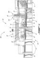
Fig. 4 , theretainer tool 60 is described in more detail. Theretainer tool 60 includes a base 61 securable to thecompressor case 31 and apin 62 extending from thebase 61. Thepin 62 is sized to be able to extend through theaperture 31B of thecompressor case 31. As illustrated more clearly inFig. 2 , thepin 62 radially overlaps thestator assembly 40 and is in abutment against thestator assembly 40 to prevent axial movements of thestator assembly 40 relative to thecompressor case 31. Put differently, theretainer tool 60 axially locks thecompressor case 31 to thestator assembly 40. Theretainer tool 60 is used for interlocking thestator assembly 40 with thecompressor case 31 when disassembling thecombustor case 32 from thecompressor case 31. - As depicted in
Figs. 3 and6 , which illustrates theretainer tool 60 and thestator assembly 40 with thecompressor case 31 removed for illustration purposes, thepin 62 extends from thebase 61 and radially inwardly through thecompressor case 31 via one of the plurality ofapertures 31B. Thepin 62 engages with thestator assembly 40 to prevent axial movement of thestator assembly 40 relative to thecompressor case 31. Thepin 62 is received through theopening 47 defined by one of the shroud supports 45 of thestator assembly 40. Thepin 62 thus abuts aperipheral wall 47A of theopening 47. Thepin 62 therefore radially overlaps at least a portion of theperipheral wall 47A that circumscribes theopening 47. A stop is therefore created between thepin 62 and thestator assembly 40. Thepin 62 may engage any suitable feature of thestator assembly 40 as long as it allows an axial retention of thestator assembly 40 relative to thecompressor case 31. Thepin 62 may engage a flange of thestator assembly 40 for instance. - As illustrated in
Figs. 5 and6 , a transverse cross-sectional profile of thepin 62 matches a shape of theopening 47 of thestator assembly 40. This may further help in maintaining a position of thestator assembly 40 relative to thecompressor case 31. Indeed, thepin 62, with its shape matching that of theopening 47, may circumferentially and axially lock the stator assembly to thecompressor case 31. This may further lessen movements of thestator assembly 40 while removing thecombustor case 32. - As more clearly illustrated in
Fig. 3 , theopening 47 of thestator assembly 40 and theaperture 31B defined through thecompressor case 31 are at least partially in register with one another. In other words, theopening 47 is visible via theaperture 31B. There is thus a direct line of sight of theopening 47 via theaperture 31B. This may help maintenance personnel in inserting theretainer tool 60 at the appropriate location. More specifically, because of this direct line of sight, thepin 62 of theretainer tool 60 is received through theopening 47 of thestator assembly 40 via a movement along a radial direction relative to thecentral axis 11. The maintenance personnel may move theretainer tool 60 along a direction being solely radial relative to thecentral axis 11. This may facilitate the insertion of theretainer tool 60. - As shown in
Fig. 4 , in the presented embodiment, thebase 61 includes atop plate 63 and abottom plate 64 secured to thetop plate 63. Thepin 62 protrudes from thebottom plate 64 of thebase 61. Thebottom plate 64 is thus disposed between thetop plate 63 and thepin 62. Thetop plate 63 extends radially outwardly beyond thebottom plate 64 relative to a pin axis P1 of thepin 62. The base 61 thus defines aperipheral flange 65, which corresponds to a portion of thetop plate 63 that overhangs past thebottom plate 64. Thebottom plate 64 has a first peripheral face 66 that intersects theperipheral flange 65 and that faces a generally radial direction relative to the pin axis P1. -
Fig. 4 also illustrates a cross-section of thecompressor case 31 with dashed lines to show how theretainer tool 60 is engaged to thecompressor case 31. As shown, theaperture 31B defined through thecompressor case 31 has a first section extending radially inwardly from anouter face 31D of thecompressor case 31 and a second section extending from the first section to aninner face 31E of thecompressor case 31. The first section has a cross-sectional area taken on a plane normal to an aperture axis A1 of theaperture 31B greater than that of the second section to define a step. Thus, theaperture 31B has an aperture peripheral face 31F that faces a radially inward direction relative to the aperture axis A1 of theaperture 31B. Theaperture 31B of thecompressor case 31 further defines ashoulder 31G that faces an axial direction relative to the aperture axis A1. Although the pin axis P1 and the aperture axis A1 appears as being coincident inFig. 4 , they may be offset from one another as will be discussed below. - The
base 61 of theretainer tool 60 includes a first locating surface 67 engaging a second locating surface 34 on thecompressor case 31. Thebase 61 is axially locked to thecompressor case 31 via an engagement of the first locating surface 67 to the second locating surface 34. In the present embodiment, the first locating surface 67 corresponds to the first peripheral face 66 of thebottom plate 64 of thebase 61 of theretainer tool 60 whereas the second locating surface 34 corresponds to the aperture peripheral face 31F. When theretainer tool 60 is properly seated, the aperture peripheral face 31F is abutted by the first peripheral face 66 of thebase 61 of theretainer tool 60 to impede axial and circumferential motions of theretainer tool 60 relative to thecentral axis 11. Theperipheral flange 65 of thebase 61 abuts theouter face 31D of thecompressor case 31 to impede movements of theretainer tool 60 along a radially inner direction relative to thecentral axis 11. - It will be appreciated that the first and second locating surfaces may be any means able to properly locate the
retainer tool 60 relative to thecompressor case 31. For instance, the first and second locating surfaces may correspond to a slot on one of the compressor case and the retainer tool and to a tab on the other of the compressor case and the retainer tool. In some embodiments, the first and second locating surfaces, although they may facilitate the installation of the retainer tool, may be omitted in some configurations. - As illustrated in
Fig. 3 , theopening 47 defined through thestator assembly 40 may be offset from the aperture axis A1 of theaperture 31B defined through thecompressor case 31. Thus, theretainer tool 60 may be secured to thecompressor case 31 in a single relative orientation. Put differently, thebase 61 is securable to thecompressor case 31 in a single relative orientation of theretainer tool 60 relative to thecompressor case 31. Maintenance personnel may be require to rotate theretainer tool 60 about the pin axis P1 until thepin 62 is suitably aligned with theopening 47 in thestator assembly 40 such that thebottom plate 64 of the base 61 may be properly seated against theshoulder 31G (Fig. 4 ) of theaperture 31B of thecompressor case 31. Markings may be provided on thetop plate 63 of the base 61 to indicate how to orient theretainer tool 60. - Referring to
Figs. 4 and6 , theperipheral flange 65 defines ahole 63A, only one illustrated but more than one may be present, in register with a respective one of threadedapertures 31H (Fig. 3 ) defined by thecompressor case 31. Afastener 68 extends through thehole 63A and is threaded in the threadedapertures 31H to maintain theretainer tool 60 secured to thecompressor case 31. - Referring now to
Fig. 7 , thecompressor case 31 is shown with a plurality ofretainer tools 60 secured to thecompressor case 31 and engaged to thestator assembly 40. As illustrated, theretainer tools 60 are circumferentially distributed about thecentral axis 11. Each of theretainer tools 60 is received within a respective aperture (e.g., bleed hole) of thecompressor case 31, secured to thecompressor case 31, and engaged to thestator assembly 40. Thus, the plurality ofretainer tools 60 may provide a substantially uniform retention force on thestator assembly 40 to prevent movements of thestator assembly 40 while disconnecting and removing the combustor case 32 (not shown inFig. 7 ). - Each of the
retainer tools 60 may have a respective base shaped to be mated with a respective bleed hole of thecompressor case 31. In other words, each bleed hole may be different in size and shape since they are each configured to supply bleed air to a respective system of thegas turbine engine 10 or to a system of an aircraft equipped with thegas turbine engine 10. Thus, theassembly 100 may include a set of retainer tools each configured to engage a respective bleed aperture defined through thecompressor case 31. - The disclosed
retainer tools 60 may thus allow to suitably lock thestator assembly 40 and thecompressor case 31 together to avoid altering a fit of thestator assembly 40 and/or deforming theseal 49 of thestator assembly 40 while removing thecombustor case 32 during overhaul or other maintenance operations. - Referring now to
Fig. 8 , a method of disassembling thecombustor case 32 from thecompressor case 31 of thegas turbine engine 10 is shown at 800. Themethod 800 includes receiving theretainer tool 60 at 802; locking thestator assembly 40 to thecompressor case 31 using theretainer tool 60 by inserting thepin 62 through theaperture 31B defined by thecompressor case 31 until thepin 62 engages thestator assembly 40 and by securing the base 61 to thecompressor case 31 at 804; and disassembling thecombustor case 32 from thecompressor case 31 when thestator assembly 40 is locked to thecompressor case 31 with the retainer tool at 806. - In the present embodiment, the locking of the
stator assembly 40 to thecompressor case 31 at 804 includes inserting thepin 62 through theopening 47 of thestator assembly 40 and abutting thepin 62 against theperipheral wall 47A of theopening 47. Theopening 47 of thestator assembly 40 and theaperture 31B of thecompressor case 31 may be at least partially in register with one another. Thus, themethod 800 includes moving theretainer tool 60 relative to thecompressor case 31 along a radial direction relative to thecentral axis 11 of thegas turbine engine 10. - The securing of the base 61 to the
compressor case 31 may include axially locking the base 61 to thecompressor case 31 by engaging the first locating surface 67 to the second locating surface 34 of thecompressor case 31. In the disclosed embodiment, the engaging of the first locating surface to the second locating surface includes abutting the first peripheral face 66 of the base 61 to the aperture peripheral face 31F of theaperture 31B of thecompressor case 31. Themethod 800 may further includes including abutting theperipheral flange 65 of theretainer tool 60 against thecompressor case 31 when thepin 62 is received through theopening 47 defined through thestator assembly 40. In some embodiments, themethod 800 includes rotating theretainer tool 60 until thepin 62 is in register with theopening 47 defined by thestator assembly 40. - The embodiments described in this document provide non-limiting examples of possible implementations of the present technology. Upon review of the present disclosure, a person of ordinary skill in the art will recognize that changes may be made to the embodiments described herein without departing from the scope of the present technology. Yet further modifications could be implemented by a person of ordinary skill in the art in view of the present disclosure, which modifications would be within the scope of the present technology.
Claims (15)
- An assembly (100) comprising:a gas turbine engine (10) including:a compressor (14) including a rotor (14C) including blades rotatable about a central axis (11) and disposed in a gas path of the gas turbine engine (10), a stator (40) including one or more vanes (42) disposed in the gas path, and a compressor case (31) disposed around the stator (40);a combustor (16) downstream of the compressor (14) along the gas path; anda combustor case (32) surrounding the combustor (16) and secured to the compressor case (31); anda retainer (60) for interlocking the stator (40) with the compressor case (31) when disassembling the combustor case (32) from the compressor case (31), the retainer (60) including:a base (61) secured to the compressor case (31); anda pin (62) extending from the base (61) and radially inwardly through the compressor case (31) via an aperture (31B) defined in the compressor case (31), the pin (62) engaging with the stator (40) to prevent axial movement of the stator (40) relative to the compressor case (31).
- The assembly (100) of claim 1, wherein the pin (62) is received into an opening (47) defined in the stator (40), the pin (62) abutting a peripheral wall (47A) of the opening (47).
- The assembly (100) of claim 2, wherein a transverse cross-sectional profile of the pin (62) matches a shape of the opening (47) of the stator (40).
- The assembly (100) of claim 2 or 3, wherein:the opening (47) of the stator (40) and the aperture (31B) of the compressor case (31) are at least partially in register with one another; and/orthe pin (62) is received through the opening (47) via a movement along a radial direction of the pin (62) relative to the central axis (11).
- The assembly (100) of any preceding claim, wherein the base (61) includes a first locating surface (67) and the compressor case (31) includes a second locating surface (34) engaged with the first locating surface (67) to axially interlock the base (61) with the compressor case (31).
- The assembly (100) of claim 6, wherein the first locating surface (67) is a first peripheral face (66) defined by the base (61) and the second locating surface (34) is a second peripheral face (31F) circumscribing the aperture (31B).
- The assembly (100) of claim 7, wherein the base (61) includes a peripheral flange (65) protruding outwardly from the first peripheral face (66), the peripheral flange (65) in abutment against the compressor case (31) when the pin (62) is received through an or the opening (47) defined through the stator (40), optionally wherein the peripheral flange (65) defines a hole (63A) in register with a threaded aperture (31H) defined by the compressor case (31), a fastener (68) extending through the hole (63A) and threaded to the threaded aperture (31H).
- The assembly (100) of any preceding claim, wherein the compressor case (31) includes a first flange (31A) and the combustor case (32) includes a second flange (32A) securable to the first flange (31A), a seal (49) sandwiched between the first flange (31A) and the second flange (32A).
- The assembly (100) of any preceding claim, wherein:the aperture (31B) is one of a plurality of apertures (31B) circumferentially distributed about the central axis (11), the retainer (60) is one of a plurality of retainers (60) each having a respective pin (62) received within a respective one of the plurality of apertures (31B), and/orthe base (61) is securable to the compressor case (31) in a single relative orientation of the retainer (60) relative to the compressor case (31).
- A method of disassembling a combustor case (32) from a compressor case (31) of a gas turbine engine (10), the compressor case (31) surrounding a stator assembly (40), the method comprising:receiving a retainer tool (60) having a base (61) and a pin (62) secured to the base (61);locking the stator assembly (40) to the compressor case (31) using the retainer tool (60) by inserting the pin (62) through an aperture (31B) defined by the compressor case (31) until the pin (62) engages the stator assembly (40) and by securing the base (61) to the compressor case (31); anddisassembling the combustor case (32) from the compressor case (31) when the stator assembly (40) is locked to the compressor case (31) with the retainer tool (60).
- The method of claim 10, wherein the locking of the stator assembly (40) to the compressor case (31) includes inserting the pin (62) through an opening (47) of the stator assembly (40) and abutting the pin (62) against a peripheral wall (47A) of the opening (47), optionally wherein the opening (47) of the stator assembly (40) and the aperture (31B) of the compressor case (31) are at least partially in register with one another.
- The method of claim 10 or 11, comprising moving the retainer tool (60) relative to the compressor case (31) along a radial direction relative to a central axis (11) of the gas turbine engine (10).
- The method of any of claims 10 to 12, wherein the securing of the base (61) to the compressor case (31) includes axially locking the base (61) to the compressor case (31) by engaging a first locating surface (67) of the base (61) to a second locating surface (34) of the compressor case (31).
- The method of claim 13, wherein the engaging of the first locating surface (67) to the second locating surface (34) includes abutting a first peripheral face (66) of the base (61) to an aperture peripheral face (31F) of the aperture (31B) of the compressor case (31), optionally wherein the base (61) includes a peripheral flange (65) protruding outwardly from the first peripheral face (66), the method including abutting the peripheral flange (65) against the compressor case (31) when the pin (62) is received through an opening (47) defined through the stator assembly (40).
- An aircraft engine repair tool (60) for disassembling a compressor case (31) from a combustor case (32) of an aircraft engine, the aircraft engine having a stator assembly (40) surrounded by the compressor case (31), the aircraft engine repair tool (60) comprising:a base (61) securable to the compressor case (31); anda pin (62) extending from the base (61), the pin (62) receivable through an aperture (31B) defined in the compressor case (31), the pin (62) engageable with the stator assembly (40) to prevent axial movement of the stator assembly (40) relative to the compressor case (31).
Applications Claiming Priority (1)
| Application Number | Priority Date | Filing Date | Title |
|---|---|---|---|
| US18/140,708 US12247518B2 (en) | 2023-04-28 | 2023-04-28 | Retainer and method for disassembling an aircraft engine |
Publications (1)
| Publication Number | Publication Date |
|---|---|
| EP4455457A1 true EP4455457A1 (en) | 2024-10-30 |
Family
ID=90923919
Family Applications (1)
| Application Number | Title | Priority Date | Filing Date |
|---|---|---|---|
| EP24173183.5A Pending EP4455457A1 (en) | 2023-04-28 | 2024-04-29 | Retainer tool and method for disassembling an aircraft engine |
Country Status (3)
| Country | Link |
|---|---|
| US (1) | US12247518B2 (en) |
| EP (1) | EP4455457A1 (en) |
| CA (1) | CA3236608A1 (en) |
Citations (8)
| Publication number | Priority date | Publication date | Assignee | Title |
|---|---|---|---|---|
| US20120195746A1 (en) * | 2011-01-27 | 2012-08-02 | General Electric Company | Turbomachine service assembly |
| JP2014066174A (en) * | 2012-09-26 | 2014-04-17 | Mitsubishi Heavy Ind Ltd | Positioning device and rotary fluid machinery having the same |
| US20150125267A1 (en) * | 2013-11-04 | 2015-05-07 | Clifford Hatcher, JR. | Standardized gas turbine inspection port system |
| US20180073397A1 (en) * | 2015-03-26 | 2018-03-15 | Mitsubishi Hitachi Power Systems, Ltd. | Securing device, steam turbine, and rotary machine manufacturing method and assembly method |
| US10167738B2 (en) * | 2013-03-14 | 2019-01-01 | United Technologies Corporation | Compressor case snap assembly |
| EP3712396A1 (en) * | 2019-03-19 | 2020-09-23 | United Technologies Corporation | Concentric jack screw holes |
| FR3115822A1 (en) * | 2020-11-04 | 2022-05-06 | Safran Aircraft Engines | MODULARITY OF AN AIRCRAFT TURBOMACHINE |
| US20220243594A1 (en) * | 2019-07-25 | 2022-08-04 | Siemens Energy Global GmbH & Co. KG | Pre-swirler adjustability in gas turbine engine |
Family Cites Families (39)
| Publication number | Priority date | Publication date | Assignee | Title |
|---|---|---|---|---|
| US2971334A (en) * | 1955-01-04 | 1961-02-14 | Solar Aircraft Co | Gas turbine engine adaptable for multi-purpose use |
| US3997962A (en) * | 1975-06-06 | 1976-12-21 | United Technologies Corporation | Method and tool for removing turbine from gas turbine twin spool engine |
| US5297932A (en) * | 1990-09-12 | 1994-03-29 | United Technologies Corporation | Fastener for multi-stage compressor |
| US5220784A (en) * | 1991-06-27 | 1993-06-22 | Allied-Signal Inc. | Gas turbine engine module assembly |
| GB9301457D0 (en) * | 1993-01-26 | 1993-03-17 | Short Brothers Plc | An aircraft propulsuve power unit |
| US5653581A (en) * | 1994-11-29 | 1997-08-05 | United Technologies Corporation | Case-tied joint for compressor stators |
| US5549448A (en) * | 1995-02-08 | 1996-08-27 | United Technolgies Corporation | Variable stator vane linkage system and method |
| US6340135B1 (en) * | 2000-05-30 | 2002-01-22 | Rohr, Inc. | Translating independently mounted air inlet system for aircraft turbofan jet engine |
| US6537022B1 (en) * | 2001-10-05 | 2003-03-25 | General Electric Company | Nozzle lock for gas turbine engines |
| US7144218B2 (en) * | 2004-04-19 | 2006-12-05 | United Technologies Corporation | Anti-rotation lock |
| US7195453B2 (en) * | 2004-08-30 | 2007-03-27 | General Electric Company | Compressor stator floating tip shroud and related method |
| JP4918263B2 (en) * | 2006-01-27 | 2012-04-18 | 三菱重工業株式会社 | Stator blade ring of axial compressor |
| US8528176B2 (en) * | 2008-10-24 | 2013-09-10 | Pratt & Whitney Canada Corp. | Diffuser case removal apparatus and method |
| US8327648B2 (en) * | 2008-12-09 | 2012-12-11 | Pratt & Whitney Canada Corp. | Combustor liner with integrated anti-rotation and removal feature |
| FR2941018B1 (en) * | 2009-01-09 | 2011-02-11 | Snecma | A VARIABLE CALIPER FOR A RECTIFIER STAGE, COMPRISING A NON-CIRCULAR INTERNAL PLATFORM |
| US8528181B2 (en) * | 2009-07-10 | 2013-09-10 | Alstom Technology Ltd | Alignment of machine components within casings |
| US10428832B2 (en) * | 2012-08-06 | 2019-10-01 | United Technologies Corporation | Stator anti-rotation lug |
| EP2971575B1 (en) * | 2013-03-13 | 2017-12-27 | United Technologies Corporation | Structural guide vane outer diameter k gussets |
| JP6082285B2 (en) * | 2013-03-14 | 2017-02-15 | 三菱日立パワーシステムズ株式会社 | Method for removing / attaching stator blade ring, and auxiliary support device for stator blade segment used in this method |
| WO2016014057A1 (en) * | 2014-07-24 | 2016-01-28 | Siemens Aktiengesellschaft | Stator vane system usable within a gas turbine engine |
| US10344624B2 (en) * | 2015-01-13 | 2019-07-09 | Rolls-Royce Corporation | Captive component on a fastener |
| US9879565B2 (en) * | 2015-01-20 | 2018-01-30 | United Technologies Corporation | Enclosed jacking insert |
| US20180112546A1 (en) * | 2015-03-17 | 2018-04-26 | SIEMENS AKTIENGESELLSCHAFTü | Stator vane dampening system usable within a turbine engine |
| US10576726B2 (en) * | 2016-03-30 | 2020-03-03 | Baker Hughes, A Ge Company, Llc | 3D-printing systems configured for advanced heat treatment and related methods |
| MX2019006638A (en) * | 2016-12-13 | 2019-08-01 | Mitsubishi Hitachi Power Sys | Gas turbine disassembling/assembling method, gas turbine rotor, and gas turbine. |
| US20180340447A1 (en) * | 2017-05-25 | 2018-11-29 | General Electric Company | Crushable spacer and bolted joint for a gas turbine engine |
| GB201711582D0 (en) * | 2017-07-19 | 2017-08-30 | Rolls Royce Plc | Unison ring assembly |
| BE1025466B1 (en) * | 2017-08-11 | 2019-03-11 | Safran Aero Boosters S.A. | TURBOMACHINE ASSEMBLY FOR BLIND MOUNTING |
| US10494956B2 (en) * | 2017-10-16 | 2019-12-03 | General Electric Company | Fastener assembly for securing a turbomachine casing and method for securing the casing |
| US11073033B2 (en) * | 2018-10-18 | 2021-07-27 | Honeywell International Inc. | Stator attachment system for gas turbine engine |
| US10815820B2 (en) * | 2019-02-05 | 2020-10-27 | Raytheon Technologies Corporation | Integral shear locking bumper for gas turbine engine |
| FR3095492B1 (en) * | 2019-04-26 | 2021-05-07 | Safran Aircraft Engines | TOOL FOR REMOVING A BLOWER DISK FROM A MODULE |
| US11111821B2 (en) * | 2019-09-18 | 2021-09-07 | Raytheon Technologies Corporation | Retention assembly for gas turbine engine |
| US11679898B2 (en) * | 2020-06-15 | 2023-06-20 | General Electric Company | Inspection and repair tool |
| US11548660B2 (en) * | 2020-08-17 | 2023-01-10 | Pratt & Whitney Canada Corp. | Aircraft engine repair tool and method for removal and installation of a rotor in an aircraft engine |
| US20240022126A1 (en) * | 2021-06-07 | 2024-01-18 | Black & Decker Inc. | Rotor magnet retention structure in brushless motor |
| JP6961856B1 (en) * | 2021-06-16 | 2021-11-05 | 三菱パワー株式会社 | Turbine assembly and how to assemble the turbine assembly |
| CN216895057U (en) * | 2022-02-09 | 2022-07-05 | 浙江华擎航空发动机科技有限公司 | Compressor stator composite structure |
| KR102727310B1 (en) * | 2022-02-23 | 2024-11-06 | 두산에너빌리티 주식회사 | Vertical joint coupling structure of casings and Gas turbine comprising the same |
-
2023
- 2023-04-28 US US18/140,708 patent/US12247518B2/en active Active
-
2024
- 2024-04-26 CA CA3236608A patent/CA3236608A1/en active Pending
- 2024-04-29 EP EP24173183.5A patent/EP4455457A1/en active Pending
Patent Citations (8)
| Publication number | Priority date | Publication date | Assignee | Title |
|---|---|---|---|---|
| US20120195746A1 (en) * | 2011-01-27 | 2012-08-02 | General Electric Company | Turbomachine service assembly |
| JP2014066174A (en) * | 2012-09-26 | 2014-04-17 | Mitsubishi Heavy Ind Ltd | Positioning device and rotary fluid machinery having the same |
| US10167738B2 (en) * | 2013-03-14 | 2019-01-01 | United Technologies Corporation | Compressor case snap assembly |
| US20150125267A1 (en) * | 2013-11-04 | 2015-05-07 | Clifford Hatcher, JR. | Standardized gas turbine inspection port system |
| US20180073397A1 (en) * | 2015-03-26 | 2018-03-15 | Mitsubishi Hitachi Power Systems, Ltd. | Securing device, steam turbine, and rotary machine manufacturing method and assembly method |
| EP3712396A1 (en) * | 2019-03-19 | 2020-09-23 | United Technologies Corporation | Concentric jack screw holes |
| US20220243594A1 (en) * | 2019-07-25 | 2022-08-04 | Siemens Energy Global GmbH & Co. KG | Pre-swirler adjustability in gas turbine engine |
| FR3115822A1 (en) * | 2020-11-04 | 2022-05-06 | Safran Aircraft Engines | MODULARITY OF AN AIRCRAFT TURBOMACHINE |
Also Published As
| Publication number | Publication date |
|---|---|
| US20240360790A1 (en) | 2024-10-31 |
| CA3236608A1 (en) | 2025-06-17 |
| US12247518B2 (en) | 2025-03-11 |
Similar Documents
| Publication | Publication Date | Title |
|---|---|---|
| US11466586B2 (en) | Turbine shroud assembly with sealed pin mounting arrangement | |
| US10995627B2 (en) | Turbine shroud with forward case and full hoop blade track | |
| EP3640440B1 (en) | Stator attachment system for gas turbine engine | |
| US11828197B2 (en) | Outlet guide vane mounting assembly for turbine engines | |
| EP0608080A1 (en) | Positioning means for a turbo engine liner | |
| US9045985B2 (en) | Stator vane bumper ring | |
| US12247518B2 (en) | Retainer and method for disassembling an aircraft engine | |
| US10774679B2 (en) | Turbine engine airfoil assembly | |
| US20200200019A1 (en) | Turbomachine disc cover mounting arrangement | |
| EP2855896B1 (en) | Stator vane mistake proofing | |
| EP1378631A2 (en) | Methods and apparatus for turbine nozzle locks | |
| CN108661727B (en) | Turbine engine bearing assembly and method of assembling same | |
| EP4202226A1 (en) | Diffuser pipe alignment tool | |
| EP3447255A1 (en) | Turbine engine with single wall cantilevered architecture | |
| US11111790B2 (en) | Method of upgrading a modular gas turbine engine | |
| US11959389B2 (en) | Turbine shroud segments with angular locating feature | |
| US12504169B2 (en) | Gas turbine engine | |
| US12516814B2 (en) | Combustor assembly with fastened combustor liner and head | |
| EP3249166A1 (en) | Turbine shroud | |
| US12631119B1 (en) | Asymmetric blade locking apparatus | |
| US12331660B1 (en) | Vane assemblies with overlapping band couplings in gas turbine engines | |
| US12398671B2 (en) | Compressor assembly for a gas turbine engine having multi-stage bleed extraction | |
| EP4737684A2 (en) | Shaft assembly for a gas turbine engine | |
| KR20230099663A (en) | Turbine nozzle assembly | |
| Grondahl et al. | MS3002 Advanced Tech Upgrade Application and Operating Experience |
Legal Events
| Date | Code | Title | Description |
|---|---|---|---|
| PUAI | Public reference made under article 153(3) epc to a published international application that has entered the european phase |
Free format text: ORIGINAL CODE: 0009012 |
|
| STAA | Information on the status of an ep patent application or granted ep patent |
Free format text: STATUS: THE APPLICATION HAS BEEN PUBLISHED |
|
| AK | Designated contracting states |
Kind code of ref document: A1 Designated state(s): AL AT BE BG CH CY CZ DE DK EE ES FI FR GB GR HR HU IE IS IT LI LT LU LV MC ME MK MT NL NO PL PT RO RS SE SI SK SM TR |
|
| STAA | Information on the status of an ep patent application or granted ep patent |
Free format text: STATUS: REQUEST FOR EXAMINATION WAS MADE |
|
| 17P | Request for examination filed |
Effective date: 20250429 |