EP4455447A1 - Fabric foreign material exclusion system - Google Patents
Fabric foreign material exclusion system Download PDFInfo
- Publication number
- EP4455447A1 EP4455447A1 EP24169998.2A EP24169998A EP4455447A1 EP 4455447 A1 EP4455447 A1 EP 4455447A1 EP 24169998 A EP24169998 A EP 24169998A EP 4455447 A1 EP4455447 A1 EP 4455447A1
- Authority
- EP
- European Patent Office
- Prior art keywords
- foreign material
- sleeve
- exclusion system
- material exclusion
- turbine
- Prior art date
- Legal status (The legal status is an assumption and is not a legal conclusion. Google has not performed a legal analysis and makes no representation as to the accuracy of the status listed.)
- Pending
Links
Images


Classifications
-
- F—MECHANICAL ENGINEERING; LIGHTING; HEATING; WEAPONS; BLASTING
- F01—MACHINES OR ENGINES IN GENERAL; ENGINE PLANTS IN GENERAL; STEAM ENGINES
- F01D—NON-POSITIVE DISPLACEMENT MACHINES OR ENGINES, e.g. STEAM TURBINES
- F01D5/00—Blades; Blade-carrying members; Heating, heat-insulating, cooling or antivibration means on the blades or the members
- F01D5/005—Repairing methods or devices
-
- F—MECHANICAL ENGINEERING; LIGHTING; HEATING; WEAPONS; BLASTING
- F01—MACHINES OR ENGINES IN GENERAL; ENGINE PLANTS IN GENERAL; STEAM ENGINES
- F01D—NON-POSITIVE DISPLACEMENT MACHINES OR ENGINES, e.g. STEAM TURBINES
- F01D25/00—Component parts, details, or accessories, not provided for in, or of interest apart from, other groups
- F01D25/24—Casings; Casing parts, e.g. diaphragms, casing fastenings
-
- F—MECHANICAL ENGINEERING; LIGHTING; HEATING; WEAPONS; BLASTING
- F01—MACHINES OR ENGINES IN GENERAL; ENGINE PLANTS IN GENERAL; STEAM ENGINES
- F01D—NON-POSITIVE DISPLACEMENT MACHINES OR ENGINES, e.g. STEAM TURBINES
- F01D25/00—Component parts, details, or accessories, not provided for in, or of interest apart from, other groups
- F01D25/28—Supporting or mounting arrangements, e.g. for turbine casing
- F01D25/285—Temporary support structures, e.g. for testing, assembling, installing, repairing; Assembly methods using such structures
-
- F—MECHANICAL ENGINEERING; LIGHTING; HEATING; WEAPONS; BLASTING
- F01—MACHINES OR ENGINES IN GENERAL; ENGINE PLANTS IN GENERAL; STEAM ENGINES
- F01D—NON-POSITIVE DISPLACEMENT MACHINES OR ENGINES, e.g. STEAM TURBINES
- F01D9/00—Stators
- F01D9/02—Nozzles; Nozzle boxes; Stator blades; Guide conduits, e.g. individual nozzles
- F01D9/04—Nozzles; Nozzle boxes; Stator blades; Guide conduits, e.g. individual nozzles forming ring or sector
-
- F—MECHANICAL ENGINEERING; LIGHTING; HEATING; WEAPONS; BLASTING
- F01—MACHINES OR ENGINES IN GENERAL; ENGINE PLANTS IN GENERAL; STEAM ENGINES
- F01D—NON-POSITIVE DISPLACEMENT MACHINES OR ENGINES, e.g. STEAM TURBINES
- F01D25/00—Component parts, details, or accessories, not provided for in, or of interest apart from, other groups
- F01D25/002—Cleaning of turbomachines
-
- F—MECHANICAL ENGINEERING; LIGHTING; HEATING; WEAPONS; BLASTING
- F05—INDEXING SCHEMES RELATING TO ENGINES OR PUMPS IN VARIOUS SUBCLASSES OF CLASSES F01-F04
- F05D—INDEXING SCHEME FOR ASPECTS RELATING TO NON-POSITIVE-DISPLACEMENT MACHINES OR ENGINES, GAS-TURBINES OR JET-PROPULSION PLANTS
- F05D2230/00—Manufacture
- F05D2230/60—Assembly methods
-
- F—MECHANICAL ENGINEERING; LIGHTING; HEATING; WEAPONS; BLASTING
- F05—INDEXING SCHEMES RELATING TO ENGINES OR PUMPS IN VARIOUS SUBCLASSES OF CLASSES F01-F04
- F05D—INDEXING SCHEME FOR ASPECTS RELATING TO NON-POSITIVE-DISPLACEMENT MACHINES OR ENGINES, GAS-TURBINES OR JET-PROPULSION PLANTS
- F05D2230/00—Manufacture
- F05D2230/70—Disassembly methods
-
- F—MECHANICAL ENGINEERING; LIGHTING; HEATING; WEAPONS; BLASTING
- F05—INDEXING SCHEMES RELATING TO ENGINES OR PUMPS IN VARIOUS SUBCLASSES OF CLASSES F01-F04
- F05D—INDEXING SCHEME FOR ASPECTS RELATING TO NON-POSITIVE-DISPLACEMENT MACHINES OR ENGINES, GAS-TURBINES OR JET-PROPULSION PLANTS
- F05D2230/00—Manufacture
- F05D2230/80—Repairing, retrofitting or upgrading methods
-
- F—MECHANICAL ENGINEERING; LIGHTING; HEATING; WEAPONS; BLASTING
- F05—INDEXING SCHEMES RELATING TO ENGINES OR PUMPS IN VARIOUS SUBCLASSES OF CLASSES F01-F04
- F05D—INDEXING SCHEME FOR ASPECTS RELATING TO NON-POSITIVE-DISPLACEMENT MACHINES OR ENGINES, GAS-TURBINES OR JET-PROPULSION PLANTS
- F05D2300/00—Materials; Properties thereof
- F05D2300/60—Properties or characteristics given to material by treatment or manufacturing
- F05D2300/601—Fabrics
Definitions
- the present application and the resultant patent relate generally to turbomachinery such as gas turbines and steam turbines and more particularly relate to a fabric foreign material exclusion system to capture foreign material such as turbine pins and other objects that may become lost during removal and replacement of turbine blades or other types of procedures.
- a gas turbine engine conventionally includes a compressor for compressing ambient air and a combustor for mixing the flow of air with a flow of fuel to generate hot combustion gases.
- a turbine receives the flow of hot combustion gases and extracts energy therefrom for powering the compressor and for producing output power for an external load such as an electrical generator and the like.
- Turbine components such as turbine buckets and blades positioned along the hot gas path are subject to not only high combustion temperatures but also different types of dynamic forces. Given such, these hot gas path components may be replaced and/or refurbished on a periodic basis to ensure efficient performance.
- Turbine blades may have a number of relatively small components such as seal pins and damper pins attached thereto. These relatively small components must be removed with the turbine blades. If a pin or other type of component were to be misplaced and left inside the turbine, the component could cause catastrophic damage upon the restart of the turbine.
- the present application and the resultant patent thus provide a foreign material exclusion system for positioning within a casing of a turbine to catch any foreign material during maintenance of the turbine.
- the foreign material exclusion system may include a fabric sleeve with a semicircular shape and a number of poles attached to the sleeve to maintain the sleeve in place within the turbine casing.
- the present application and the resultant patent further provide a method of inserting a foreign material exclusion system into a casing of a turbine about a number of stages thereof.
- the method may include the steps of sliding a sleeve between the casing and the number of stages, inserting one or more poles into the sleeve, attaching the sleeve to the casing with one or more sled hooks, and attaching one or more horizontal joint frame plates to the sleeve.
- the present application and the resultant patent further provide a foreign material exclusion system for positioning within a casing of a turbine to catch any foreign material during maintenance of the turbine.
- the foreign material exclusion system may include a fabric sleeve with a semicircular shape, a number of channels formed therein, and a horizontal joint frame plate. A number of poles may be positioned within the channels to maintain the sleeve in place within the turbine casing.
- Fig. 1 shows a schematic diagram of a gas turbine engine 10 as may be used herein.
- the gas turbine engine 10 may include a compressor 15.
- the compressor 15 compresses an incoming flow of air 20.
- the compressor 15 delivers the compressed flow of air 20 to a number of combustor cans 25.
- the combustor cans 25 mix the compressed flow of air 20 with a pressurized flow of fuel 30 and ignite the mixture to create a flow of hot combustion gases 35.
- the gas turbine engine 10 may include any number of combustor cans 25 positioned in a circumferential array and the like.
- the combustor 25 may be an annular combustor.
- the flow of combustion gases 35 is in turn delivered to a turbine 40.
- the flow of combustion gases 35 drives the turbine 40 to produce mechanical work.
- the mechanical work produced in the turbine 40 drives the compressor 15 via a rotor shaft 45 and an external load 50 such as an electrical generator and the like.
- the gas turbine engine 10 may use natural gas, various types of syngas, liquid fuels, and/or other types of fuels and blends thereof.
- the gas turbine engine 10 may be any one of a number of different gas turbine engines offered by General Electric Company of Schenectady, New York, including, but not limited to, those such as a 7-series or a 9-series heavy duty gas turbine engine and the like.
- the gas turbine engine 10 may be part of a simple cycle or a combined cycle power generation system or other types of generation systems.
- the gas turbine engine 10 may have different configurations and may use other types of components. Other types of gas turbine engines also may be used herein. Multiple gas turbine engines, other types of turbines, and other types of power generation equipment also may be used herein together.
- Fig. 2 is a partial sectional view of the turbine 40.
- the turbine 40 includes a number of stages 52.
- each stage 52 includes a stationary row 54 of stator vanes 56 and a rotating row 58 of turbine blades 60.
- three stages 52 are shown, a first stage, a second stage, and a third stage.
- the turbine blades 60 in each row 58 are spaced circumferentially about, and extend radially outward from, a rotor disk 62.
- Each rotor disk 62 is coupled to the rotor shaft 45.
- a turbine casing 64 extends circumferentially about the stator vanes 56.
- stator vanes 56 are each coupled to the turbine casing 64 and each stator vane 56 extends radially inward from the casing 64 towards the rotor shaft 45.
- a hot combustion gas path 66 is defined between the turbine casing 64 and each rotor disk 62.
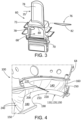
- Fig. 3 shows an example of a turbine blade 60 of the turbine 40.
- the turbine blade 60 may include a shank 68, a dovetail 70, a platform 72, and an airfoil 74.
- the dovetail 70 secures the turbine blade 60 to a periphery of the rotor disk 62.
- the platform 72 defines an inward flow boundary for the combustion gases 35 flowing through the hot combustion gas path 66.
- a damper pin 76 may be located along one axial edge (or slash face) 78 adjacent to (i.e., radially inward of) the platform 72.
- the damper pin 76 maybe located in an elongated groove 80 that extends along the slash face 78 of the turbine blade 60.
- the damper pin 76 frictionally dissipates vibratory energy and reduces corresponding amplitude of vibration.
- a similar damper pin 76 may be located between each adjacent pair of turbine blades 60.
- Other types of pins such as seal pins and the like also may be used herein. During the deblading process and other types of maintenance, the pins 76 and the like may become a foreign material 82 capable of damage to the turbine 40 if not accounted for and removed.
- the foreign material exclusion system 100 may include a sleeve 110.
- the sleeve 110 may have a substantial semicircular shape 120. Specifically, the sleeve 110 may be sized and shaped to fit within a lower half of the casing 64.
- the sleeve 110 may extend across several stages 52.
- the sleeve 110 may be made out of a fabric 130.
- the fabric 130 may include woven plastic mesh, nonwoven synthetic material, impregnated resins, natural porous fibers such as cotton, heavy duty waterproof and temperature resistant material, or any flexible, formable surface covering, and similar types of materials and blends thereof.
- the sleeve 110 may include a base wall 140 extending from a first end 150 to a second end 160, a first sidewall 170, and a second sidewall 180.
- the base wall 140 and the sidewalls 170, 180 may be sown together to form the sleeve 110.
- zippers clasp lockers
- the sidewalls 170, 180 may have channels 190 formed in an inner edge 200 and an outer edge 210 thereof.
- the channels 190 may be sized for the elongated poles 220 to be positioned therein.
- the elongated poles 220 may be curved in the semicircular shape 120 and serve to provide rigidity to the sleeve 110.
- the elongated poles 220 may be made out of any substantially rigid material such as plastics, steel or metal such as aluminum and titanium, carbon fiber, fiberglass, combinations thereof, and the like. As is shown in Fig. 7 and as will be described in more detail below, the poles 220 of the sleeve 110 may be tensioned and held in place by a number of rigid fiber collets 230 and the like. Other types of tensioning devices may be used herein. Other components and other configurations may be used herein.
- the first and second ends 150, 160 of the base wall 140 may have magnets 240 and the like sewn or otherwise positioned therein.
- the magnets 240 are attracted to the metal of the lower half of the casing 64 to keep the sleeve 110 in place.
- different types of weights and the like also may be used.
- the first and second ends 150, 160 of the base wall 140 also may be held in place by a number of sled hooks 250.
- the sled hooks 250 pin the fabric 130 into position within the casing 64 along the ends 150, 160 of the base wall 140.
- the sled hooks 250 may be sized to accommodate specific shroud hook geometry and the like of a predetermined stage.
- the sled hooks 250 may capture the sleeve 110 to the circumference of the casing 64 via the poles 220 and the like.
- the first and second ends 150, 160 of the base wall 140 may be covered by a horizontal joint frame plate 260.
- the horizontal joint frame plate 260 may be sized and shaped to ensure that the horizontal joint of the casing 64 is enclosed.
- the horizontal joint frame plate 260 may include a pair of flanges 270 that extend on either side of the stages 52.
- the horizontal joint frame plate 260 also may include a number of pole apertures 280 for the elongated poles 220 to extend therethrough. The elongated poles 220 aid in maintaining the horizontal joint frame plate 260 in position.
- Other components and other configurations may be used herein.
- the foreign material exclusion system 100 may be slid into place about the lower half of the casing 64 beneath rows 58 of the turbine blades 60.
- the custom fit sleeve 110 may be positioned into place, the elongated poles 220 may be positioned within the channels 190, and the elongated poles 220 may be tensioned via the rigid fiber collets 230.
- the elongated poles 220 may provide the tight fit of the fabric 130 of the sleeve 110 to the casing 64. Given such, the tight fit avoids bunching of the fabric 130.
- the magnets 240 sewn in on both ends 150, 160 of the sleeve 110 hold the sleeve 110 in position and enable optimal folding of the fabric 130 when removing the sleeve 110 from the casing 64. This optimal folding ensures that any foreign material that fell into the sleeve 110 during the procedure is contained and safely removed.
- the horizontal joint frame plates 260 on the horizontal joints of the casing 64 keep the fabric 130 in place and close off all possible foreign material pathways about the ends thereof.
- the sled hooks 250 ensure the proper guidance of the fabric 130 of the sleeve 110 into position.
- the use of the fabric 130 for the sleeve 110 of the foreign material exclusion system 100 thus provides a custom fit that may be resistant of wear, tear, and heat.
- the custom fit thus provides maximum protection from foreign material entrance into the turbine area.
- the use of the elongated poles 220 in the semicircular shape 120 ensures that the sleeve 110 maintains the correct position with respect to the curvature of the casing 64.
- the foreign material exclusion system 100 thus reduces the opportunity for foreign object damage during hot gas path inspection, deblading, and other procedures.
Landscapes
- Engineering & Computer Science (AREA)
- Mechanical Engineering (AREA)
- General Engineering & Computer Science (AREA)
- Structures Of Non-Positive Displacement Pumps (AREA)
Abstract
The present application provides a foreign material exclusion system (100) for positioning within a casing (64) of a turbine (40) to catch any foreign material (82) during maintenance of the turbine (40). The foreign material exclusion system (100) may include a fabric sleeve (110) with a semicircular shape (120) and a number of poles (190) attached to the sleeve (110) to maintain the sleeve (110) in place within the turbine casing (64).
Description
- The present application and the resultant patent relate generally to turbomachinery such as gas turbines and steam turbines and more particularly relate to a fabric foreign material exclusion system to capture foreign material such as turbine pins and other objects that may become lost during removal and replacement of turbine blades or other types of procedures.
- A gas turbine engine conventionally includes a compressor for compressing ambient air and a combustor for mixing the flow of air with a flow of fuel to generate hot combustion gases. A turbine receives the flow of hot combustion gases and extracts energy therefrom for powering the compressor and for producing output power for an external load such as an electrical generator and the like. Turbine components such as turbine buckets and blades positioned along the hot gas path are subject to not only high combustion temperatures but also different types of dynamic forces. Given such, these hot gas path components may be replaced and/or refurbished on a periodic basis to ensure efficient performance.
- Turbine blades may have a number of relatively small components such as seal pins and damper pins attached thereto. These relatively small components must be removed with the turbine blades. If a pin or other type of component were to be misplaced and left inside the turbine, the component could cause catastrophic damage upon the restart of the turbine.
- Current foreign material exclusion systems may use a large tarp that is positioned under the rotating turbine components to catch foreign material such as the pins and the like. The tarp may be secured by taping the tarp to the casing. The tarp, however, tends to bunch up under the rotating components and may be snagged and/or may slip under the rotating components. Such snagging or slipping may allow a pin or other type of foreign material to escape into the turbine, particularly when removing the tarp. Given such, foreign material remains a significant issue during turbine maintenance and other procedures.
- The present application and the resultant patent thus provide a foreign material exclusion system for positioning within a casing of a turbine to catch any foreign material during maintenance of the turbine. The foreign material exclusion system may include a fabric sleeve with a semicircular shape and a number of poles attached to the sleeve to maintain the sleeve in place within the turbine casing.
- The present application and the resultant patent further provide a method of inserting a foreign material exclusion system into a casing of a turbine about a number of stages thereof. The method may include the steps of sliding a sleeve between the casing and the number of stages, inserting one or more poles into the sleeve, attaching the sleeve to the casing with one or more sled hooks, and attaching one or more horizontal joint frame plates to the sleeve.
- The present application and the resultant patent further provide a foreign material exclusion system for positioning within a casing of a turbine to catch any foreign material during maintenance of the turbine. The foreign material exclusion system may include a fabric sleeve with a semicircular shape, a number of channels formed therein, and a horizontal joint frame plate. A number of poles may be positioned within the channels to maintain the sleeve in place within the turbine casing.
- These and other features and improvements of this application and the resultant patent will become apparent to one of ordinary skill in the art upon review of the following detailed description when taken in conjunction with the several drawings and the appended claims.
-
-
Fig. 1 is a schematic diagram of a gas turbine engine including a compressor, a combustor, a turbine, and an external load. -
Fig. 2 is a schematic diagram of a number of stages positioned within a casing of a turbine. -
Fig. 3 is a perspective view of a turbine blade. -
Fig. 4 is a perspective view of a foreign material exclusion system as may be described herein. -
Fig. 5 is a further perspective view of the foreign material exclusion system ofFig. 4 . -
Fig. 6 is a perspective view of a rigid fiber collet for use with the foreign material exclusion system ofFig. 4 . -
Fig. 7 is a perspective view of a sled hook for use with the foreign material exclusion system ofFig. 4 . -
Fig. 8 is a perspective view of the foreign material exclusion system ofFig. 4 positioned within the casing of the turbine. - Referring now to the drawings, in which like numerals refer to like elements throughout the several views,
Fig. 1 shows a schematic diagram of agas turbine engine 10 as may be used herein. Thegas turbine engine 10 may include acompressor 15. Thecompressor 15 compresses an incoming flow ofair 20. Thecompressor 15 delivers the compressed flow ofair 20 to a number ofcombustor cans 25. The combustor cans 25 mix the compressed flow ofair 20 with a pressurized flow offuel 30 and ignite the mixture to create a flow ofhot combustion gases 35. Although only a single combustor can 25 is shown, thegas turbine engine 10 may include any number ofcombustor cans 25 positioned in a circumferential array and the like. Alternatively, thecombustor 25 may be an annular combustor. The flow ofcombustion gases 35 is in turn delivered to aturbine 40. The flow ofcombustion gases 35 drives theturbine 40 to produce mechanical work. The mechanical work produced in theturbine 40 drives thecompressor 15 via arotor shaft 45 and anexternal load 50 such as an electrical generator and the like. - The
gas turbine engine 10 may use natural gas, various types of syngas, liquid fuels, and/or other types of fuels and blends thereof. Thegas turbine engine 10 may be any one of a number of different gas turbine engines offered by General Electric Company of Schenectady, New York, including, but not limited to, those such as a 7-series or a 9-series heavy duty gas turbine engine and the like. Thegas turbine engine 10 may be part of a simple cycle or a combined cycle power generation system or other types of generation systems. Thegas turbine engine 10 may have different configurations and may use other types of components. Other types of gas turbine engines also may be used herein. Multiple gas turbine engines, other types of turbines, and other types of power generation equipment also may be used herein together. -
Fig. 2 is a partial sectional view of theturbine 40. Theturbine 40 includes a number ofstages 52. Generally described, eachstage 52 includes astationary row 54 ofstator vanes 56 and a rotatingrow 58 ofturbine blades 60. In this example, threestages 52 are shown, a first stage, a second stage, and a third stage. Theturbine blades 60 in eachrow 58 are spaced circumferentially about, and extend radially outward from, arotor disk 62. Eachrotor disk 62 is coupled to therotor shaft 45. Aturbine casing 64 extends circumferentially about thestator vanes 56. Thestator vanes 56 are each coupled to theturbine casing 64 and eachstator vane 56 extends radially inward from thecasing 64 towards therotor shaft 45. A hotcombustion gas path 66 is defined between theturbine casing 64 and eachrotor disk 62. -
Fig. 3 shows an example of aturbine blade 60 of theturbine 40. Theturbine blade 60 may include ashank 68, adovetail 70, aplatform 72, and anairfoil 74. Thedovetail 70 secures theturbine blade 60 to a periphery of therotor disk 62. Theplatform 72 defines an inward flow boundary for thecombustion gases 35 flowing through the hotcombustion gas path 66. Adamper pin 76 may be located along one axial edge (or slash face) 78 adjacent to (i.e., radially inward of) theplatform 72. Specifically, thedamper pin 76 maybe located in anelongated groove 80 that extends along theslash face 78 of theturbine blade 60. Thedamper pin 76 frictionally dissipates vibratory energy and reduces corresponding amplitude of vibration. Asimilar damper pin 76 may be located between each adjacent pair ofturbine blades 60. Other types of pins such as seal pins and the like also may be used herein. During the deblading process and other types of maintenance, thepins 76 and the like may become aforeign material 82 capable of damage to theturbine 40 if not accounted for and removed. -
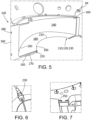
Figs. 4 and5 show an example of a foreignmaterial exclusion system 100 as may be described herein. The foreignmaterial exclusion system 100 may include a sleeve 110. The sleeve 110 may have a substantial semicircular shape 120. Specifically, the sleeve 110 may be sized and shaped to fit within a lower half of thecasing 64. The sleeve 110 may extend acrossseveral stages 52. The sleeve 110 may be made out of a fabric 130. The fabric 130 may include woven plastic mesh, nonwoven synthetic material, impregnated resins, natural porous fibers such as cotton, heavy duty waterproof and temperature resistant material, or any flexible, formable surface covering, and similar types of materials and blends thereof. - Generally described, the sleeve 110 may include a
base wall 140 extending from afirst end 150 to asecond end 160, afirst sidewall 170, and asecond sidewall 180. Thebase wall 140 and thesidewalls sidewalls channels 190 formed in aninner edge 200 and anouter edge 210 thereof. Thechannels 190 may be sized for theelongated poles 220 to be positioned therein. Theelongated poles 220 may be curved in the semicircular shape 120 and serve to provide rigidity to the sleeve 110. Theelongated poles 220 may be made out of any substantially rigid material such as plastics, steel or metal such as aluminum and titanium, carbon fiber, fiberglass, combinations thereof, and the like. As is shown inFig. 7 and as will be described in more detail below, thepoles 220 of the sleeve 110 may be tensioned and held in place by a number ofrigid fiber collets 230 and the like. Other types of tensioning devices may be used herein. Other components and other configurations may be used herein. - The first and second ends 150, 160 of the
base wall 140 may havemagnets 240 and the like sewn or otherwise positioned therein. Themagnets 240 are attracted to the metal of the lower half of thecasing 64 to keep the sleeve 110 in place. Alternatively, different types of weights and the like also may be used. The first and second ends 150, 160 of thebase wall 140 also may be held in place by a number of sled hooks 250. As is shown inFig. 8 and described in more detail below, the sled hooks 250 pin the fabric 130 into position within thecasing 64 along theends base wall 140. The sled hooks 250 may be sized to accommodate specific shroud hook geometry and the like of a predetermined stage. The sled hooks 250 may capture the sleeve 110 to the circumference of thecasing 64 via thepoles 220 and the like. - The first and second ends 150, 160 of the
base wall 140 may be covered by a horizontaljoint frame plate 260. The horizontaljoint frame plate 260 may be sized and shaped to ensure that the horizontal joint of thecasing 64 is enclosed. The horizontaljoint frame plate 260 may include a pair offlanges 270 that extend on either side of thestages 52. The horizontaljoint frame plate 260 also may include a number ofpole apertures 280 for theelongated poles 220 to extend therethrough. Theelongated poles 220 aid in maintaining the horizontaljoint frame plate 260 in position. Other components and other configurations may be used herein. - In use as is shown in
Fig. 8 , the foreignmaterial exclusion system 100 may be slid into place about the lower half of thecasing 64 beneathrows 58 of theturbine blades 60. Specifically, the custom fit sleeve 110 may be positioned into place, theelongated poles 220 may be positioned within thechannels 190, and theelongated poles 220 may be tensioned via therigid fiber collets 230. Theelongated poles 220 may provide the tight fit of the fabric 130 of the sleeve 110 to thecasing 64. Given such, the tight fit avoids bunching of the fabric 130. Themagnets 240 sewn in on both ends 150, 160 of the sleeve 110 hold the sleeve 110 in position and enable optimal folding of the fabric 130 when removing the sleeve 110 from thecasing 64. This optimal folding ensures that any foreign material that fell into the sleeve 110 during the procedure is contained and safely removed. The horizontaljoint frame plates 260 on the horizontal joints of thecasing 64 keep the fabric 130 in place and close off all possible foreign material pathways about the ends thereof. Likewise, the sled hooks 250 ensure the proper guidance of the fabric 130 of the sleeve 110 into position. - The use of the fabric 130 for the sleeve 110 of the foreign
material exclusion system 100 thus provides a custom fit that may be resistant of wear, tear, and heat. The custom fit thus provides maximum protection from foreign material entrance into the turbine area. The use of theelongated poles 220 in the semicircular shape 120 ensures that the sleeve 110 maintains the correct position with respect to the curvature of thecasing 64. The foreignmaterial exclusion system 100 thus reduces the opportunity for foreign object damage during hot gas path inspection, deblading, and other procedures. - It should be apparent that the foregoing relates only to certain embodiments of this application and resultant patent. Numerous changes and modifications may be made herein by one of ordinary skill in the art without departing from the general spirit and scope of the invention as defined by the following claims and the equivalents thereof.
- Further aspects of the invention are provided by the subject matter of the following clauses:
- 1. A foreign material exclusion system for positioning within a casing of a turbine to catch any foreign material during maintenance of the turbine, comprising a sleeve with a semicircular shape; the sleeve comprising a fabric; and a plurality of poles attached to the sleeve to maintain the sleeve in place within the turbine casing.
- 2. The foreign material exclusion system of any preceding clause, wherein the sleeve comprises a base wall, a first sidewall, and a second sidewall.
- 3. The foreign material exclusion system of any preceding clause, wherein the first sidewall and the second sidewall comprise a plurality of channels to accommodate the plurality of poles.
- 4. The foreign material exclusion system of any preceding clause, wherein the first sidewall and the second sidewall comprise an inner edge and an outer edge and wherein the inner edge and the outer edge both accommodate one of the plurality of channels therein.
- 5. The foreign material exclusion system of any preceding clause, wherein the base wall comprises a first end and a second end.
- 6. The foreign material exclusion system of any preceding clause, wherein the first end and the second end comprises a plurality of magnets therein.
- 7. The foreign material exclusion system of any preceding clause, wherein the first end and the second end comprise one or more sled hooks thereon.
- 8. The foreign material exclusion system of any preceding clause, wherein the one or more sled hooks are sized for a predetermined stage of the turbine.
- 9. The foreign material exclusion system of any preceding clause, wherein the first end and the second end comprise a horizontal joint frame plate thereon.
- 10. The foreign material exclusion system of any preceding clause, wherein the horizontal joint frame plate comprises a pair of flanges thereon.
- 11. The foreign material exclusion system of any preceding clause, wherein the horizontal joint frame plate comprises a plurality of pole apertures sized to accommodate the plurality of poles.
- 12. The foreign material exclusion system of any preceding clause, wherein the base wall, the first sidewall, and the second sidewall are sewn or zippered together.
- 13. The foreign material exclusion system of any preceding clause, wherein the plurality of poles each comprise a rigid fiber collet for tensioning.
- 14. The foreign material exclusion system of any preceding clause, wherein the fabric comprises natural or synthetic materials.
- 15. A method of inserting a foreign material exclusion system into a casing of a turbine about a number of stages thereof, comprising: sliding a sleeve between the casing and the number of stages; inserting one or more poles into the sleeve; attaching the sleeve to the casing with one or more sled hooks; and attaching one or more horizontal joint frame plates to the sleeve.
- 16. A foreign material exclusion system for positioning within a casing of a turbine to catch any foreign material during maintenance of the turbine, comprising: a sleeve with a semicircular shape; the sleeve comprising a fabric; the sleeve comprising a plurality of channels therein; a plurality of poles positioned within the plurality of channel to maintain the sleeve in place within the turbine casing; and a horizontal joint frame plate positioned about the sleeve.
- 17. The foreign material exclusion system of any preceding clause, wherein the sleeve comprises a plurality of magnets therein.
- 18. The foreign material exclusion system of any preceding clause, wherein the sleeve comprises one or more sled hooks thereon.
- 19. The foreign material exclusion system of any preceding clause, wherein the plurality of poles each comprise a rigid fiber collet for tensioning.
- 20. The foreign material exclusion system of any preceding clause, wherein the fabric comprises natural or synthetic materials.
Claims (15)
- A foreign material exclusion system (100) for positioning within a casing (64) of a turbine (40) to catch any foreign material (82) during maintenance of the turbine (40), comprising:a sleeve (110) with a semicircular shape (120);the sleeve (110) comprising a fabric (130); anda plurality of poles (220) attached to the sleeve (110) to maintain the sleeve (110) in place within the turbine casing (64).
- The foreign material exclusion system (100) of claim 1, wherein the sleeve (110) comprises a base wall (140), a first sidewall (170), and a second sidewall (180).
- The foreign material exclusion system (100) of claim 2, wherein the first sidewall (170) and the second sidewall (180) comprise a plurality of channels (190) to accommodate the plurality of poles (220).
- The foreign material exclusion system (100) of claim 3, wherein the first sidewall (170) and the second sidewall (180) comprise an inner edge (200) and an outer edge (210) and wherein the inner edge (200) and the outer edge (210) both accommodate one of the plurality of channels (190) therein.
- The foreign material exclusion system (100) of claim 2, wherein the base (140) wall comprises a first end (150) and a second end (160).
- The foreign material exclusion system (100) of claim 5, wherein the first end (150) and the second end (160) comprises a plurality of magnets (240) therein.
- The foreign material exclusion system (100) of claim 5, wherein the first end (150) and the second end (160) comprise one or more sled hooks (250) thereon.
- The foreign material exclusion system (100) of claim 7, wherein the one or more sled hooks (250) are sized for a predetermined stage (52) of the turbine (40).
- The foreign material exclusion system (100) of claim 5, wherein the first end (150) and the second end (160) comprise a horizontal joint frame plate (260) thereon.
- The foreign material exclusion system (100) of claim 9, wherein the horizontal joint frame plate (260) comprises a pair of flanges (270) thereon.
- The foreign material exclusion system (100) of claim 9, wherein the horizontal joint frame plate (260) comprises a plurality of pole apertures (280) sized to accommodate the plurality of poles (190).
- The foreign material exclusion system (100) of claim 2, wherein the base wall (140), the first sidewall (170), and the second sidewall (180) are sewn or zippered together.
- The foreign material exclusion system (100) of claim 1, wherein the plurality of poles (190) each comprise a rigid fiber collet (230) for tensioning.
- The foreign material exclusion system (100) of claim 1, wherein the fabric (130) comprises natural or synthetic materials.
- A method of inserting a foreign material exclusion system (100) into a casing (64) of a turbine (40) about a number of stages (52) thereof, comprising:sliding a sleeve (110) between the casing (64) and the number of stages (52);inserting one or more poles (190) into the sleeve (110);attaching the sleeve (110) to the casing (64) with one or more sled hooks (250); andattaching one or more horizontal joint frame plates (260) to the sleeve (110).
Applications Claiming Priority (1)
| Application Number | Priority Date | Filing Date | Title |
|---|---|---|---|
| PL44468823 | 2023-04-28 |
Publications (1)
| Publication Number | Publication Date |
|---|---|
| EP4455447A1 true EP4455447A1 (en) | 2024-10-30 |
Family
ID=90730129
Family Applications (1)
| Application Number | Title | Priority Date | Filing Date |
|---|---|---|---|
| EP24169998.2A Pending EP4455447A1 (en) | 2023-04-28 | 2024-04-12 | Fabric foreign material exclusion system |
Country Status (5)
| Country | Link |
|---|---|
| US (1) | US12320267B2 (en) |
| EP (1) | EP4455447A1 (en) |
| JP (1) | JP2024159548A (en) |
| KR (1) | KR20240159484A (en) |
| CN (1) | CN118896004A (en) |
Citations (3)
| Publication number | Priority date | Publication date | Assignee | Title |
|---|---|---|---|---|
| US6109843A (en) * | 1999-07-02 | 2000-08-29 | United Technologies Corporation | Shield assembly for masking a stator of a rotary machine |
| US20100095984A1 (en) * | 2002-05-13 | 2010-04-22 | Shahin Tadayon | Gaspath cleaning system |
| EP2998061B1 (en) * | 2014-09-22 | 2019-07-10 | Rolls-Royce Deutschland Ltd & Co KG | Method and device for machining the blade tips of a compressor rotor of a gas turbine |
Family Cites Families (4)
| Publication number | Priority date | Publication date | Assignee | Title |
|---|---|---|---|---|
| US5809770A (en) * | 1995-07-31 | 1998-09-22 | Donaldson Company, Inc. | Silencer for a gas flow |
| FR2933130B1 (en) * | 2008-06-25 | 2012-02-24 | Snecma | STRUCTURAL CASING FOR TURBOMACHINE |
| US10823063B2 (en) * | 2018-02-13 | 2020-11-03 | General Electric Company | Foreign object damage screen assembly for a gas turbine engine |
| GB201813498D0 (en) * | 2018-08-20 | 2018-10-03 | Rolls Royce | Fan blade removal method and tooling |
-
2024
- 2024-04-09 JP JP2024062469A patent/JP2024159548A/en active Pending
- 2024-04-12 EP EP24169998.2A patent/EP4455447A1/en active Pending
- 2024-04-22 KR KR1020240053191A patent/KR20240159484A/en active Pending
- 2024-04-23 US US18/643,156 patent/US12320267B2/en active Active
- 2024-04-24 CN CN202410495631.9A patent/CN118896004A/en active Pending
Patent Citations (3)
| Publication number | Priority date | Publication date | Assignee | Title |
|---|---|---|---|---|
| US6109843A (en) * | 1999-07-02 | 2000-08-29 | United Technologies Corporation | Shield assembly for masking a stator of a rotary machine |
| US20100095984A1 (en) * | 2002-05-13 | 2010-04-22 | Shahin Tadayon | Gaspath cleaning system |
| EP2998061B1 (en) * | 2014-09-22 | 2019-07-10 | Rolls-Royce Deutschland Ltd & Co KG | Method and device for machining the blade tips of a compressor rotor of a gas turbine |
Also Published As
| Publication number | Publication date |
|---|---|
| US12320267B2 (en) | 2025-06-03 |
| US20240360773A1 (en) | 2024-10-31 |
| KR20240159484A (en) | 2024-11-05 |
| CN118896004A (en) | 2024-11-05 |
| JP2024159548A (en) | 2024-11-08 |
Similar Documents
| Publication | Publication Date | Title |
|---|---|---|
| CN103388492B (en) | Turbine system as well as system and method used for turbine rotor | |
| US7094029B2 (en) | Methods and apparatus for controlling gas turbine engine rotor tip clearances | |
| US8425194B2 (en) | Clamped plate seal | |
| EP2354451A2 (en) | Turbine seal plate assembly | |
| EP2612995A2 (en) | Turbine nozzle compartmentalized cooling system | |
| CN110836130B (en) | Turbine, gas turbine and turbine blade separation method | |
| US20080292466A1 (en) | Method to center locate cutter teeth on shrouded turbine blades | |
| US12320267B2 (en) | Fabric foreign material exclusion system | |
| EP2615253A1 (en) | Turbine Vane Seal Carrier with Slots for Cooling and Assembly | |
| EP2354458A2 (en) | Locking spacer assembly | |
| WO2014068355A1 (en) | Gas turbine engine exhaust system and corresponding method for accessing turbine buckets | |
| US9470098B2 (en) | Axial compressor and method for controlling stage-to-stage leakage therein | |
| EP2562359A2 (en) | Turbine nozzle vane retention system | |
| CN204212817U (en) | Comprise the turbo machine of the non-destructive fastener element for connected element | |
| JP5998045B2 (en) | Turbine nozzle cooling assembly | |
| EP2653661A2 (en) | Turbomachine blade mounting system | |
| US9309776B2 (en) | Replaceable seals for turbine engine components and methods for installing the same | |
| US9506359B2 (en) | Transition nozzle combustion system | |
| CN203867973U (en) | Compressor outer shell assembly and turbine engine with the same | |
| JP7171297B2 (en) | turbine exhaust diffuser | |
| BR102024008138A2 (en) | TISSUE FOREIGN MATERIAL EXCLUSION SYSTEM | |
| US20140023502A1 (en) | Variable vane assembly for turbine system |
Legal Events
| Date | Code | Title | Description |
|---|---|---|---|
| PUAI | Public reference made under article 153(3) epc to a published international application that has entered the european phase |
Free format text: ORIGINAL CODE: 0009012 |
|
| STAA | Information on the status of an ep patent application or granted ep patent |
Free format text: STATUS: THE APPLICATION HAS BEEN PUBLISHED |
|
| AK | Designated contracting states |
Kind code of ref document: A1 Designated state(s): AL AT BE BG CH CY CZ DE DK EE ES FI FR GB GR HR HU IE IS IT LI LT LU LV MC ME MK MT NL NO PL PT RO RS SE SI SK SM TR |
|
| STAA | Information on the status of an ep patent application or granted ep patent |
Free format text: STATUS: REQUEST FOR EXAMINATION WAS MADE |
|
| 17P | Request for examination filed |
Effective date: 20250423 |
|
| RAP3 | Party data changed (applicant data changed or rights of an application transferred) |
Owner name: GE VERNOVA TECHNOLOGY GMBH |