EP4455437A1 - System to assist with fire resistance of a door - Google Patents
System to assist with fire resistance of a door Download PDFInfo
- Publication number
- EP4455437A1 EP4455437A1 EP24172138.0A EP24172138A EP4455437A1 EP 4455437 A1 EP4455437 A1 EP 4455437A1 EP 24172138 A EP24172138 A EP 24172138A EP 4455437 A1 EP4455437 A1 EP 4455437A1
- Authority
- EP
- European Patent Office
- Prior art keywords
- retaining device
- base
- frame member
- door
- infill panel
- Prior art date
- Legal status (The legal status is an assumption and is not a legal conclusion. Google has not performed a legal analysis and makes no representation as to the accuracy of the status listed.)
- Granted
Links
Images



Classifications
-
- E—FIXED CONSTRUCTIONS
- E06—DOORS, WINDOWS, SHUTTERS, OR ROLLER BLINDS IN GENERAL; LADDERS
- E06B—FIXED OR MOVABLE CLOSURES FOR OPENINGS IN BUILDINGS, VEHICLES, FENCES OR LIKE ENCLOSURES IN GENERAL, e.g. DOORS, WINDOWS, BLINDS, GATES
- E06B3/00—Window sashes, door leaves, or like elements for closing wall or like openings; Layout of fixed or moving closures, e.g. windows in wall or like openings; Features of rigidly-mounted outer frames relating to the mounting of wing frames
- E06B3/54—Fixing of glass panes or like plates
- E06B3/5481—Fixing of glass panes or like plates by means of discrete fixing elements, e.g. glazing clips, glaziers points
-
- E—FIXED CONSTRUCTIONS
- E06—DOORS, WINDOWS, SHUTTERS, OR ROLLER BLINDS IN GENERAL; LADDERS
- E06B—FIXED OR MOVABLE CLOSURES FOR OPENINGS IN BUILDINGS, VEHICLES, FENCES OR LIKE ENCLOSURES IN GENERAL, e.g. DOORS, WINDOWS, BLINDS, GATES
- E06B5/00—Doors, windows, or like closures for special purposes; Border constructions therefor
- E06B5/10—Doors, windows, or like closures for special purposes; Border constructions therefor for protection against air-raid or other war-like action; for other protective purposes
- E06B5/16—Fireproof doors or similar closures; Adaptations of fixed constructions therefor
- E06B5/161—Profile members therefor
-
- E—FIXED CONSTRUCTIONS
- E06—DOORS, WINDOWS, SHUTTERS, OR ROLLER BLINDS IN GENERAL; LADDERS
- E06B—FIXED OR MOVABLE CLOSURES FOR OPENINGS IN BUILDINGS, VEHICLES, FENCES OR LIKE ENCLOSURES IN GENERAL, e.g. DOORS, WINDOWS, BLINDS, GATES
- E06B5/00—Doors, windows, or like closures for special purposes; Border constructions therefor
- E06B5/10—Doors, windows, or like closures for special purposes; Border constructions therefor for protection against air-raid or other war-like action; for other protective purposes
- E06B5/16—Fireproof doors or similar closures; Adaptations of fixed constructions therefor
- E06B5/162—Fireproof doors having windows or other openings, e.g. for permitting ventilation or escape
-
- E—FIXED CONSTRUCTIONS
- E06—DOORS, WINDOWS, SHUTTERS, OR ROLLER BLINDS IN GENERAL; LADDERS
- E06B—FIXED OR MOVABLE CLOSURES FOR OPENINGS IN BUILDINGS, VEHICLES, FENCES OR LIKE ENCLOSURES IN GENERAL, e.g. DOORS, WINDOWS, BLINDS, GATES
- E06B3/00—Window sashes, door leaves, or like elements for closing wall or like openings; Layout of fixed or moving closures, e.g. windows in wall or like openings; Features of rigidly-mounted outer frames relating to the mounting of wing frames
- E06B3/04—Wing frames not characterised by the manner of movement
- E06B3/263—Frames with special provision for insulation
- E06B2003/26394—Strengthening arrangements in case of fire
Definitions
- the present disclosure generally relates to fire doors and, in particular, to: a retaining device for use in retaining an infill panel in a fire door; and a method of installing an infill panel in a fire door using said retaining device.
- Fire-rated doors are doors constructed of materials that work together to slow or stop the spread of flames, smoke and, in certain applications, radiant and conductive heat transfer. Common materials utilised in fire-rated door construction include wood, steel, fiberglass, fire-rated glass, and combinations of these materials.
- Fire-rated door assemblies are given a fire rating determined through standardised tests. Typically, fire-rated doors are subjected to a fire endurance test to determine their fire rating. This test is used to measure how long the door remains intact without failure under application of extreme heat, i.e., the fire resistance of the door.
- each door leaf of a fire door comprises a frame and at least one infill panel retained within the frame. The quicker an infill panel breaks or fails to perform its function during a fire, the lower the fire resistance and thereby fire rating of the fire door.
- One potential way in which a door leaf may fail during a fire is if an infill panel of the door leaf falls out of the frame of the door leaf: the fallen infill panel is no longer able to perform its function of preventing the spread of fire through the door leaf. Therefore, it would be advantageous to provide a fire door assembly wherein the infill panel or infill panels are retained more securely within each door leaf.
- One way of improving the retention of an infill panel within a door leaf is attaching the infill panel to the frame of the door leaf using a retaining device.
- a portion of the retaining device is generally bent against the infill panel, to thereby grip the infill panel, using a glazing tool.
- the glazing tool tends to slip (e.g. away from the infill panel) while being used to apply a force to bend the retaining device.
- the infill panel is therefore not gripped as tightly by the retaining device and is more prone to failure (i.e., falling out of the frame) during a fire.
- the second issue is that the installation of the infill panel is more challenging and/or slower because the person installing the retaining device needs to be careful to avoid the glazing tool slipping.
- the person installing the retaining device needs to reapply a force to bend the retaining device, further increasing the time and physical exertion required to complete installation and wearing out the person installing the retaining device more quickly.
- An additional downside to slipping of the glazing tool is that the desired angle of bend cannot be achieved easily, safely, and without risk of infill panel damage.
- the present disclosure solves these problems by providing an improved retaining device, which can be positioned inside existing fire doors and facilitates easier and more consistent infill panel installation.
- One aspect of the present disclosure is directed to a fire door comprising at least one door leaf, wherein each door leaf comprises a frame and at least one infill panel retained within the frame.
- the frame comprises: a first frame member and a second frame member spaced from the first frame member; a glazing bead attached to the second frame member; and at least one retaining device for retaining one of the at least one infill panels between the first frame member and the glazing bead.
- the retaining device is made of a material having a melting point of at least 1000 °C, preferably at least 1400 °C, and comprises: an L-shaped portion located at a first end of the retaining device, the L-shaped portion comprising: a first base attached to the first frame member; and a wall extending upwardly from the first base, wherein the wall contacts a first side of the infill panel; a second base located at a second end of the retaining device, wherein the second base is attached to the second frame member; a middle portion located intermediate the first end and the second end and adjacent the second base, wherein the middle portion comprises: a raised surface raised with respect to the second base; and a sidewall joining the raised surface to the second base; and at least one leg extending from an edge of the raised surface adjacent the sidewall, wherein the at least one leg is bent upwardly against a second side of the infill panel, and wherein the infill panel is gripped between the wall and the at least one leg.
- the second base includes a protrusion
- the infill panel is made of fire-rated glass.
- the infill panel is made of one or more fire retardant materials clad in aluminum or aluminum alloy.
- the protrusion 60 acts as both a support and point of rotation for a glazing tool 190 when bending the at least one leg 40A, 40B.
- the protrusion 60 also acts indicates the location where the glazing tool 190 must be inserted, i.e., between the protrusion 60 and the side wall 510.
- the protrusion 60 may add to the strength of the retaining device 1 by acting as a stiffening rib.
- first and/or second frame member and/or glazing bead are made from aluminum or an aluminum alloy. More preferably, each of the first frame member, the second frame member and the glazing bead are made from aluminum or an aluminum alloy.
- the material the retaining device is made of is compatible with aluminum.
- the retaining device is made of stainless steel.
- the L-shaped portion has an angle of 90° or less between the first base and the wall.
- the angle is in a range of 90°-85°.
- the retaining device comprises at least two legs. More preferably, the retaining device comprises two legs.
- the retaining device may be attached to each of the first and second frame members by one or more fastening elements.
- the retaining device is attached to each of the first and second frame members by one or more screws.
- the protrusion or additional piece may extend parallel to the corner between the sidewall and second base.
- the door is a swing door.
- the second base may preferably comprise a curved lip located at the second end of the retaining device, wherein the curved lip is configured for receipt within a feature of the second frame member.
- the door may further comprise at least one fixed door leaf.
- a further aspect of the present disclosure is directed to a retaining device for use in retaining an infill panel in a fire door, wherein the retaining device is made of a material having a melting point of at least 1000 °C, preferably at least 1400 °C, and wherein the retaining device comprises: an L-shaped portion located at a first end of the retaining device, the L-shaped portion comprising: a first base for attachment to a first frame member of a fire door; and a wall extending upwardly from the first base; a second base for attachment to a second frame member of a fire door located at a second end of the retaining device; a middle portion located intermediate the first end and the second end and adjacent the second base, wherein the middle portion comprises: a raised surface raised with respect to the second base; and a sidewall joining the raised surface to the second base; and at least one leg extending from an edge of the raised surface adjacent the sidewall towards the second end of the retaining device.
- the second base includes a protrusion spaced from the middle portion, or the retaining device includes an additional piece comprising a third means for attachment to a top surface of the second base wherein, when the additional piece is attached to the top surface of the second base, the additional piece is spaced from the middle portion.
- the material the retaining device is made of may have a higher melting point than: a material which the first frame member is made of; and a material which second frame member is made of.
- the material the retaining device is made of is compatible with aluminum.
- the retaining device is made of stainless steel.
- the L-shaped portion has an angle of 90° or less between the first base and the wall.
- the angle is in a range of 90°-85°.
- the retaining device comprises at least two legs. More preferably, the retaining device comprises two legs.
- the retaining device may be configured for attachment to each of the first and second frame members by one or more fastening elements.
- the retaining device comprises one or more screw holes or slots such that the retaining device is attachable to each of the first and second frame members by one or more screws.
- the protrusion or additional piece may extend parallel to the corner between the sidewall and second base.
- the second base may preferably comprise a curved lip located at the second end of the retaining device, wherein the curved lip is configured for receipt within a feature of a second frame member.
- Also provided herein is a method of installing an infill panel in a frame of a door leaf of a fire door using at least one retaining device, wherein the frame comprises: a first frame member and a second frame member spaced from the first frame member; and a glazing bead for attaching to the second frame member, and wherein the method comprises: attaching the first base of the retaining device to the first frame member and the second base of the retaining device to the second frame member; where the retaining device comprises the additional piece, attaching the additional piece to the second base; placing the infill panel between the first frame member and the second frame member; placing a forward edge of a glazing tool in a corner formed by the sidewall of the middle portion and the second base of the retaining device; while using the protrusion or additional piece as support, bending the at least one leg upwardly by pivoting the glazing tool until the at least one leg is pressed against the infill panel, and attaching the glazing bead to the second frame member.
- a kit comprising at least one retaining device and a glazing tool for use in bending the at least one leg of the retaining device, wherein the glazing tool comprises: a wedged portion located at a first end; and a handle located at a second end, wherein the handle comprises a gripping portion, and wherein the gripping portion comprises a longitudinal axis parallel to a forward edge of the wedged portion.
- a retaining device 1 comprises from a first end 70 to a second end 80: an L-shaped portion 180, a middle portion 30 and a second base 50.
- the L-shaped portion 180 comprises a first base 20 and a wall 10 extending upwardly from the first base 20.
- the L-shaped portion comprises an angle 500 of 90° or less between the first base 20 and the wall 10.
- the angle 500 may be in a range of 90°-85°, 90°-80°, 90°-75°, 90°-70° or 90°-60°.
- the middle portion 30 comprises a raised surface 520, raised with respect to the second base 50, a sidewall 510 joining the raised surface 520 to the second base 50 and at least one leg 40A, 40B extending from an edge of the raised surface 520 adjacent the sidewall 510 towards the second end 80 of the retaining device 1.
- the raised surface 520 is also raised with respect to the first base 20.
- the at least one leg 40A, 40B extending from an edge of the raised surface 520 adjacent the sidewall 510 towards the second end 80 of the retaining device 1 may be parallel to the second base 50.
- the retaining device 1 comprises at least two legs 40A, 40B.
- the retaining device 1 comprises two legs 40A, 40B. It can be appreciated that it is advantageous for the retaining device 1 to comprise more than one leg 40A, 40B in case of breakage or failure of an at least one leg 40A, 40B: the retaining device 1 may still function to retain an infill panel. It is particularly advantageous for the retaining device 1 to comprise 2 legs 40A, 40B, e.g., as depicted, due to ease of manufacture.
- the second base 50 comprises a protrusion 60 extending from a top surface 530 thereof, wherein the protrusion 60 is spaced from the middle portion 30 of the retaining device 1.
- the protrusion 60 extends along the top surface 530 parallel to the corner joining the sidewall 510 and second base 50.
- the protrusion 60 extends along the top surface 530 parallel to the corner joining the sidewall 510 and second base 50 across an entire width of the second base 50.
- a fire door of the present disclosure comprises at least one door leaf 100 (i.e., door panel).
- the fire door may be a swing door.
- the at least one door leaf 100 comprises at least one fixed door leaf (i.e., a door leaf not movable between an open and a closed position).
- the at least one door leaf 100 comprises a frame and at least one infill panel 140 retained within the frame.
- the at least one door leaf 100 of the present disclosure may comprise 1, 2, 3, 4, 5, 6 or more infill panels 140.
- the at least one infill panel 140 may be made of a fire-rated material, such as fire-rated glass, wood or steel.
- the at least one infill panel 140 is made of fire-rate glass.
- the at least one infill panel may be made of one or more fire retardant materials clad in aluminum or aluminum alloy.
- the frame of the present disclosure comprises a first frame member 120, a second frame member 130, a glazing bead 110 and at least one retaining device 1.
- the first frame member 120 and/or second frame member 130 and/or glazing bead 110 are made from aluminum or an aluminum alloy.
- each of the first frame member 120, the second frame member 130 and the glazing bead 110 are made from aluminum or an aluminum alloy.
- the first frame member 120, the second frame member 130 and the glazing bead 110 may be made from extruded aluminum or aluminum alloy.
- the second frame member 130 is spaced from the first frame member 120.
- the first frame member 120 and the second frame member 130 are separated by a thermal break 150.
- the thermal break 150 may connect the first and second frame members 120, 130 as depicted in figure 2 .
- the glazing bead 110 is attachable to the second frame member 130.
- the glazing bead 110 may be clipped to the second frame member 130 in the assembled door leaf 100.
- the at least one retaining device 1 acts to retain one of the at least one infill panels 140 between the first frame member 120 and the glazing bead 110.
- the at least one retaining device 1 is made of a material having a melting point of at least 1000 °C, preferably at least 1400 °C. It is advantageous to provide the retaining device with a melting point higher than the typical temperature reached by a building fire to prevent the retaining device 1 melting or softening during a fire.
- the retaining device 1 is able to retain the infill panel 140 within the frame when the door leaf 100 is subjected to the temperatures and forces of a building fire, thereby preventing spread of the fire from one side of the door leaf 100 to the other.
- the material the retaining device 1 has a higher melting point than: a material which the first frame member 120 is made of; and a material which second frame member 130 is made of. It can be appreciated that it is advantageous for the retaining device 1 to have a higher melting point than the first and/or second frame members 120, 130: this allows the retaining device 1 to retain its structural integrity and ability to retain the infill panel 140 within the frame even if exterior portions of the frame begin to melt or soften during a fire.
- the first and/or second frame member 120, 130 and/or glazing bead 110 are made from aluminum or an aluminum alloy
- the material the retaining device 1 is made of preferably is compatible with aluminum.
- the material of the retaining device 1 may be compatible with aluminum for preventing corrosion of the frame and/or retaining device 1.
- the retaining device 1 may be made of stainless steel.
- Stainless steel is preferred because of its high melting point, ranging from 1400°C to 1530 °C. Stainless steel also possesses good compatibility with aluminum.
- the wall 10 of the at least one retaining device 1 contacts a first side 200 of the at least one infill panel 140. This helps hold the at least one infill panel 140 in place by limiting the infill panel's 140 movement.
- the first base 20 of the at least one retaining device 1 is attached to the first frame member 120.
- the first base 20 comprises a first means of attachment 170A for attachment to the first frame member 120.
- the first means of attachment 170A may include one or more fastening elements 540A.
- the first base 20 of the at least one retaining device 1 may be attached to the first frame member 120 by one or more screws 540A.
- the first base 20 may comprise one or more screw holes or slots for receiving the one or more screws 540A therethrough.
- the second base 50 of the at least one retaining device 1 is attached to the second frame member 130.
- the second base 50 comprises a second means of attachment 170B for attachment to the second frame member 130.
- the second means of attachment 170B may include one or more fastening elements 540B.
- the second base 50 of the at least one retaining device 1 may be attached to the second frame member 130 by one or more screws 540B.
- the second base 50 may comprise one or more screw holes or slots for receiving the one or more screws 540B therethrough.
- the first means of attachment 170A and the second means of attachment 170B may be the same.
- the middle portion 30 comprises a raised surface 520 raised with respect to both the second base 50 and the first base 20, this is advantageous.
- the raised surface 520 provides additional room for components, such as additional insulating material, to be placed between the first and second frame members 120, 130.
- the height of the sidewall 510 i.e., the offset of the raised surface 520 with respect to the second base 50
- the dimensions of the at least one retaining device 1 may scaled according to the infill panel 140 and/or frame size.
- the second base 50 of the at least one retaining device 1 may comprise a curved lip 90 located at the second end 80 of the at least one retaining device 1.
- the curved lip 90 may be configured for receipt within a feature 210 of the second frame member 130.
- a curved lip 90 is advantageous for facilitating correct attachment of the at least one retaining device 1 to the first and second frame members 120, 130: receipt of the curved lip 90 in the feature 210 assists with correctly locating the retaining device 1 during installation.
- a feature 210 for receiving the curved lip 90 is a protrusion having a T-shaped cross-section as depicted.
- the second base 50 may comprise a locating feature other than a curved lip 90 for locating the retaining device 1 in the second frame member 130 during installation.
- FIGS 3A and 3B depict an alternative retaining device 1000 according to the present disclosure.
- the retaining device 1000 includes an additional piece 220, in place of a protrusion 60.
- the retaining device 1000 is identical to the retaining device 1 of figure 2 and may comprise any and all of the features of the retaining device 1 described above.
- the additional piece 220 may comprise a third means of attachment 170C for attaching the additional piece 220 to a top surface 530 of the second base 50.
- the third means of attachment 170C may include one or more fastening elements.
- the additional piece 220 may be attached to the top surface 530 of the second base 50 of the at least one retaining device 1000 by one or more screws 540C.
- additional piece 220 is attached to the top surface 530 via one or more screws which also attach the second base 50 to the second frame member 130. This is advantageous for simplifying installation of the retaining device 1000 on the frame members 120, 130.
- the additional piece 220 is spaced from the middle portion 30 of the retaining device 1000 when attached.
- the additional piece 220 comprises a front edge 700 extending parallel to a corner joining the sidewall 510 and second base 50.
- the front edge 700 of the additional piece 220 may extend parallel to the corner joining the sidewall 510 and second base 50 across an entire width of the second base 50.
- the at least one leg 40A, 40B of a retaining device 1, 1000 according to the present disclosure is bent upwardly during assembly of a fire door according to the present disclosure. Bending of the at least one leg 40A, 40B allows the at least one leg to be pressed against the second side 230 of the infill panel 140.
- the infill panel 140 is gripped between the wall 10 and the at least one leg 40A, 40B, after the leg has been bent upwardly against the second side 230 of the infill panel 140.
- the contact between the wall 10 and the at least one leg 40A, 40B retains the infill panel 140 within the frame of the door leaf 100.
- a door leaf 100 may comprise one or more retaining devices 1, 1000 for retaining an infill panel 140 within the frame located on two or more edges of the infill panel 140.
- each edge of the infill panel 140 may be held by one or more retaining devices 1,1000.
- the optimum number and arrangement (e.g., location of and or spacing between) of retaining devices for retaining an infill panel 140 within the frame of a door leaf 100 will depend on the size and weight of the infill panel 140 and the size of the retaining device 1, 1000.
- a glazing tool 190 comprises from a first end 250 to a second end 260, a wedged portion 270 and a handle 280.
- the handle 280 comprises a gripping portion 290 having a longitudinal axis parallel to a forward edge 300 of the wedged portion 270.
- the glazing tool 190 may be used to bend the at least one leg 40A, 40B of the at least one retaining device 1, 1000 of the present disclosure.
- the glazing tool 190 is made of a plastic material.
- a kit comprising a glazing tool 190 and at least one retaining device 1, 1000 as described herein.
- the present disclosure further provides a method of installing an infill panel 140 in a frame of a door leaf 100 of a fire door using at least one retaining device 1, 1000 of the present disclosure.
- the method of installing an infill panel 140 in a frame of a door leaf 100 of a fire door using at least one retaining device 1 comprises attaching the first base 20 of the retaining device 1 to the first frame member 120 and the second base 50 of the retaining device 1 to the second frame member 130.
- the infill panel 140 is then placed in between the first frame member 120 and the second frame member 130 and in contact with the wall 10. Subsequently, the forward edge of a glazing tool, such as the glazing tool 190 of the present disclosure, is placed in the corner joining the sidewall 510 of the middle portion 30 to the second base 50 of the retaining device 1.
- the at least one leg 40A, 40B is then bent by pivoting the glazing tool, while using the protrusion 60 as support, until the at least one leg 40A, 40B is pressed against the infill panel 140.
- a glazing bead 110 is then attached to the second frame member 130.
- the glazing tool 190 when the forward edge of a glazing tool 190 is placed in the corner joining the sidewall 510 to the second base 50, the glazing tool 190 is located between the second base 50 and the at least one leg 40A, 40B. As the glazing tool 190 is pivoted in the in direction of the infill panel 140, the glazing tool 190 contacts the at least one leg 40A, 40B. The force exerted on the at least one leg 40A, 40B by the glazing tool 190 cause the at least one leg 40A, 40B to bend in a direction towards the infill panel 140. This highlights the importance of the raised surface 520, which raises the at least one leg 40A, 40B with respect to the second base 50. Without the raised surface 520, the glazing tool 190 would not be able to be inserted under the at least one leg 40A, 40B.
- a glazing tool 190 it is possible to place the forward edge of a glazing tool 190 in the corner joining the sidewall 510 and the second base 50 of the retaining device 1, because the protrusion 60 extending from the top surface 530 of the second base 50 is spaced from the sidewall 510.
- the protrusion 60 acts to prevent the glazing tool 190 from slipping backwards in a direction away from the sidewall 510 when being pivoted to bend the at least one leg 40A, 40B. Reducing slippage of the glazing tool 190 allows the desired angle of bend of the at least one leg 40A, 40B to be achieved more consistently, while also reducing the physical effort exerted by the installer, i.e., person installing the retaining device 1 and infill panel 140.
- the desired angle of bend is 90°, wherein the angle of bend is measured between the second base 50 and the at least one leg 40A, 40B.
- An angle of bend of 90° achieves the greatest contact area between the at least one leg 40A, 40B and the second side 230 of the infill panel 140. In other words, this desired angle allows the infill panel 140 to be held most securely within the frame, thereby reducing the likelihood of the infill panel 140 falling out of the frame, in particular in the event of a fire either side of the door.
- the retaining device 1 of the present disclosure achieves, on average, an angle of bend of the at least one leg of between 85-90°.
- a retaining device not comprising a protrusion 60 but otherwise identical to the retaining device 1 of the present disclosure achieves, on average, an angle of bend of the at least one leg of between 70-90°. Accordingly, the protrusion 60 helps to achieve a more consistent angle of bend.
- the protrusion 60 also facilitates installation of the infill panel 140.
- the protrusion 60 may increase the speed of installation of the infill panel 140 in the frame by up to 65 % when compared to installing an infill panel using a retaining device not comprising the protrusion 60 but otherwise identical.
- the protrusion 60 acts as both a support and point of rotation for a glazing tool 190 when bending the at least one leg 40A, 40B.
- the protrusion 60 also acts to indicate the location where the glazing tool 190 must be inserted in the retaining device 1, i.e., between the protrusion 60 and the side wall 510.
- the protrusion 60 may add to the strength of the retaining device 1 by acting as a stiffening rib.
- the present disclosure further provides a method of installing an infill panel 140 in a frame of a door leaf 100 of a fire door using at least one retaining device 1000 of the present disclosure.
- the method of installing an infill panel 140 in a frame of a door leaf 100 of a fire door using at least one retaining device 1000 comprises attaching the first base 20 of the retaining device 1000 to the first frame member 120 and the second base 50 of the retaining device 1000 to the second frame member 130.
- the additional piece 220 is attached to the second base 50.
- the infill panel 140 is then placed in between the first frame member 120 and the second frame member 130.
- a glazing tool 190 such as the glazing tool 190 of the present disclosure
- the forward edge of a glazing tool 190 is placed in the corner joining the sidewall 510 of the middle portion 30 to the second base 50 of the retaining device 1000.
- the at least one leg 40A, 40B is then bent by pivoting the glazing tool 190, while using the additional piece 220 as support, until the at least one leg 40A, 40B is pressed against the infill panel 140.
- a glazing bead 110 is then attached to the second frame member 130.
- the additional piece 220 is attached to the second base 50 at the same time as the second base 50 is attached to the second frame member 130.
- the glazing tool 190 when the forward edge of a glazing tool 190 is placed in the corner joining the sidewall 510 to the second base 50, the glazing tool 190 is located between the second base 50 and the at least one leg 40A, 40B. As the glazing tool 190 is pivoted in the in direction of the infill panel 140, the glazing tool 190 contacts the at least one leg 40A, 40B. The force exerted on the at least one leg 40A, 40B by the glazing tool 190 cause the at least one leg 40A, 40B to bend in a direction towards the infill panel 140.
- a front edge 700 of the additional piece 220 acts to prevent the glazing tool 190 from slipping backwards in a direction away from the sidewall 510 when being pivoted to bend the at least one leg 40A, 40B. Reducing slippage of the glazing tool 190 allows the desired angle of bend of the at least one leg 40A, 40B to be achieved more consistently, while also reducing the physical effort exerted by the installer.
- the desired angle of bend is 90°, wherein the angle of bend is measured between the second base 50 and the at least one leg 40A, 40B.
- An angle of bend of 90° achieves the greatest contact area between the at least one leg 40A, 40B and the second side 230 of the infill panel 140.
- this desired angle allows the infill panel 140 to be held most securely within the frame, thereby reducing the likelihood of the infill panel 140 falling out of the frame, in particular in the event of a fire either side of the door.
- the retaining device 1000 of the present disclosure like the retaining device 1, achieves, on average, an angle of bend of the at least one leg of between 85-90°.
- a retaining device not comprising an additional piece 220 but otherwise identical to the retaining device 1000 of the present disclosure achieves, on average, an angle of bend of the at least one leg of between 70-90°. Accordingly, the additional piece 220 helps to achieve a more consistent angle of bend, while also reducing the physical effort exerted by the installer.
- the additional piece 220 also facilitates installation of the infill panel 140.
- the additional piece 220 may increase the speed of installation of the infill panel 140 in the frame by up to 65 % when compared to installing an infill panel using a retaining device not comprising the additional piece 220 but otherwise identical.
- the front edge 700 of the additional piece acts as both a support and point of rotation for a glazing tool 190 when bending the at least one leg 40A, 40B.
- the front edge 700 also acts to indicate the location where the glazing tool 190 must be inserted in the retaining device 1000, i.e., between the front edge 700 and the side wall 510.
- the glazing tool 190 of the present disclosure is advantageous when used in the methods as described herein.
- the glazing tool 190 comprises a gripping portion 290 having a longitudinal axis parallel to a forward edge 300 of the wedged portion 270.
- This gripping portion 290 facilitates pivoting of the glazing tool 290 toward the infill panel 140, i.e., makes this movement easier and more comfortable for the user.
- the glazing tool 190 reduces the time taken to install the retaining device 1, 1000 when compared to a known glazing tool.
- the disclosure may also broadly consist in the parts, elements, steps, examples and/or features referred to or indicated in the specification individually or collectively in any and all combinations of two or more said parts, elements, steps, examples and/or features.
- one or more features in any of the embodiments described herein may be combined with one or more features from any other embodiment(s) described herein.
Landscapes
- Engineering & Computer Science (AREA)
- Civil Engineering (AREA)
- Structural Engineering (AREA)
- Special Wing (AREA)
Abstract
Description
- The present disclosure generally relates to fire doors and, in particular, to: a retaining device for use in retaining an infill panel in a fire door; and a method of installing an infill panel in a fire door using said retaining device.
- Fire-rated doors (i.e., fire doors) are doors constructed of materials that work together to slow or stop the spread of flames, smoke and, in certain applications, radiant and conductive heat transfer. Common materials utilised in fire-rated door construction include wood, steel, fiberglass, fire-rated glass, and combinations of these materials.
- Fire-rated door assemblies are given a fire rating determined through standardised tests. Typically, fire-rated doors are subjected to a fire endurance test to determine their fire rating. This test is used to measure how long the door remains intact without failure under application of extreme heat, i.e., the fire resistance of the door.
- One way of increasing fire resistance of a fire door is by increasing the fire resistance of the door leaf or door leaves (i.e. door panel or door panels) of said fire door. Commonly, each door leaf of a fire door comprises a frame and at least one infill panel retained within the frame. The quicker an infill panel breaks or fails to perform its function during a fire, the lower the fire resistance and thereby fire rating of the fire door. One potential way in which a door leaf may fail during a fire is if an infill panel of the door leaf falls out of the frame of the door leaf: the fallen infill panel is no longer able to perform its function of preventing the spread of fire through the door leaf. Therefore, it would be advantageous to provide a fire door assembly wherein the infill panel or infill panels are retained more securely within each door leaf.
- One way of improving the retention of an infill panel within a door leaf is attaching the infill panel to the frame of the door leaf using a retaining device. During installation of the infill panel in the door leaf, a portion of the retaining device is generally bent against the infill panel, to thereby grip the infill panel, using a glazing tool. However, for known retaining devices, the glazing tool tends to slip (e.g. away from the infill panel) while being used to apply a force to bend the retaining device. There are two main issues that result from this slipping of the glazing tool. The first is that the portion of the retaining device being bent is not consistently bent through the desired angle, e.g. 90°. The infill panel is therefore not gripped as tightly by the retaining device and is more prone to failure (i.e., falling out of the frame) during a fire. The second issue is that the installation of the infill panel is more challenging and/or slower because the person installing the retaining device needs to be careful to avoid the glazing tool slipping. Furthermore, when the glazing tool slips, the person installing the retaining device needs to reapply a force to bend the retaining device, further increasing the time and physical exertion required to complete installation and wearing out the person installing the retaining device more quickly. An additional downside to slipping of the glazing tool is that the desired angle of bend cannot be achieved easily, safely, and without risk of infill panel damage.
- The present disclosure solves these problems by providing an improved retaining device, which can be positioned inside existing fire doors and facilitates easier and more consistent infill panel installation.
- One aspect of the present disclosure is directed to a fire door comprising at least one door leaf, wherein each door leaf comprises a frame and at least one infill panel retained within the frame. The frame comprises: a first frame member and a second frame member spaced from the first frame member; a glazing bead attached to the second frame member; and at least one retaining device for retaining one of the at least one infill panels between the first frame member and the glazing bead. The retaining device is made of a material having a melting point of at least 1000 °C, preferably at least 1400 °C, and comprises: an L-shaped portion located at a first end of the retaining device, the L-shaped portion comprising: a first base attached to the first frame member; and a wall extending upwardly from the first base, wherein the wall contacts a first side of the infill panel; a second base located at a second end of the retaining device, wherein the second base is attached to the second frame member; a middle portion located intermediate the first end and the second end and adjacent the second base, wherein the middle portion comprises: a raised surface raised with respect to the second base; and a sidewall joining the raised surface to the second base; and at least one leg extending from an edge of the raised surface adjacent the sidewall, wherein the at least one leg is bent upwardly against a second side of the infill panel, and wherein the infill panel is gripped between the wall and the at least one leg. The second base includes a protrusion extending from a top surface thereof and spaced from the middle portion, or the retaining device includes an additional piece attached to the top surface of the second base and spaced from the middle portion.
- Preferably, the infill panel is made of fire-rated glass. Alternatively, the infill panel is made of one or more fire retardant materials clad in aluminum or aluminum alloy.
- The
protrusion 60 acts as both a support and point of rotation for aglazing tool 190 when bending the at least oneleg protrusion 60 also acts indicates the location where theglazing tool 190 must be inserted, i.e., between theprotrusion 60 and theside wall 510. In some arrangements, theprotrusion 60 may add to the strength of theretaining device 1 by acting as a stiffening rib. - Preferably, the first and/or second frame member and/or glazing bead are made from aluminum or an aluminum alloy. More preferably, each of the first frame member, the second frame member and the glazing bead are made from aluminum or an aluminum alloy.
- Advantageously, the material the retaining device is made of is compatible with aluminum. Preferably, the retaining device is made of stainless steel.
- In preferred aspects, the L-shaped portion has an angle of 90° or less between the first base and the wall. Preferably, the angle is in a range of 90°-85°.
- Preferably, the retaining device comprises at least two legs. More preferably, the retaining device comprises two legs.
- The retaining device may be attached to each of the first and second frame members by one or more fastening elements. Preferably, the retaining device is attached to each of the first and second frame members by one or more screws.
- The protrusion or additional piece may extend parallel to the corner between the sidewall and second base.
- In preferred aspects, the door is a swing door.
- The second base may preferably comprise a curved lip located at the second end of the retaining device, wherein the curved lip is configured for receipt within a feature of the second frame member.
- The door may further comprise at least one fixed door leaf.
- A further aspect of the present disclosure is directed to a retaining device for use in retaining an infill panel in a fire door, wherein the retaining device is made of a material having a melting point of at least 1000 °C, preferably at least 1400 °C, and wherein the retaining device comprises: an L-shaped portion located at a first end of the retaining device, the L-shaped portion comprising: a first base for attachment to a first frame member of a fire door; and a wall extending upwardly from the first base; a second base for attachment to a second frame member of a fire door located at a second end of the retaining device; a middle portion located intermediate the first end and the second end and adjacent the second base, wherein the middle portion comprises: a raised surface raised with respect to the second base; and a sidewall joining the raised surface to the second base; and at least one leg extending from an edge of the raised surface adjacent the sidewall towards the second end of the retaining device. The second base includes a protrusion spaced from the middle portion, or the retaining device includes an additional piece comprising a third means for attachment to a top surface of the second base wherein, when the additional piece is attached to the top surface of the second base, the additional piece is spaced from the middle portion.
- The material the retaining device is made of may have a higher melting point than: a material which the first frame member is made of; and a material which second frame member is made of.
- Advantageously, the material the retaining device is made of is compatible with aluminum. Preferably, the retaining device is made of stainless steel.
- In preferred aspects, the L-shaped portion has an angle of 90° or less between the first base and the wall. Preferably, the angle is in a range of 90°-85°.
- Preferably, the retaining device comprises at least two legs. More preferably, the retaining device comprises two legs.
- The retaining device may be configured for attachment to each of the first and second frame members by one or more fastening elements. Preferably, the retaining device comprises one or more screw holes or slots such that the retaining device is attachable to each of the first and second frame members by one or more screws.
- The protrusion or additional piece may extend parallel to the corner between the sidewall and second base.
- The second base may preferably comprise a curved lip located at the second end of the retaining device, wherein the curved lip is configured for receipt within a feature of a second frame member.
- Also provided herein is a method of installing an infill panel in a frame of a door leaf of a fire door using at least one retaining device, wherein the frame comprises: a first frame member and a second frame member spaced from the first frame member; and a glazing bead for attaching to the second frame member, and wherein the method comprises: attaching the first base of the retaining device to the first frame member and the second base of the retaining device to the second frame member; where the retaining device comprises the additional piece, attaching the additional piece to the second base; placing the infill panel between the first frame member and the second frame member; placing a forward edge of a glazing tool in a corner formed by the sidewall of the middle portion and the second base of the retaining device; while using the protrusion or additional piece as support, bending the at least one leg upwardly by pivoting the glazing tool until the at least one leg is pressed against the infill panel, and attaching the glazing bead to the second frame member.
- Lastly provided herein is a kit comprising at least one retaining device and a glazing tool for use in bending the at least one leg of the retaining device, wherein the glazing tool comprises: a wedged portion located at a first end; and a handle located at a second end, wherein the handle comprises a gripping portion, and wherein the gripping portion comprises a longitudinal axis parallel to a forward edge of the wedged portion.
- In order that the present disclosure may be more readily understood, preferable aspects thereof will now be described, by way of example only, with reference to the accompanying drawings, in which:
-
FIGURE 1A is a perspective view of a retaining device in accordance with the present disclosure; -
FIGURE 1B is a plan view of the retaining device offigure 1A ; -
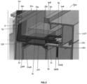
FIGURE 2 is a cross-sectional view of a door leaf in accordance with the present disclosure; -
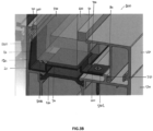
FIGURE 3A is a perspective view of a retaining device attached to a first frame member and a second frame member in accordance with the present disclosure; -
FIGURE 3B is a cross-sectional view of a door leaf comprising the retaining device offigure 3A , wherein the at least one leg of the retaining device is not shown; and -
FIGURE 4 is a perspective view of a glazing tool in accordance with the present disclosure. - According to the present disclosure there is provided a retaining device. As shown in
figures 1A and 1B , a retainingdevice 1 according to the present disclosure comprises from afirst end 70 to a second end 80: an L-shapedportion 180, amiddle portion 30 and asecond base 50. The L-shapedportion 180 comprises afirst base 20 and awall 10 extending upwardly from thefirst base 20. In some aspects, the L-shaped portion comprises anangle 500 of 90° or less between thefirst base 20 and thewall 10. Preferably, theangle 500 may be in a range of 90°-85°, 90°-80°, 90°-75°, 90°-70° or 90°-60°. - As depicted, the
middle portion 30 comprises a raisedsurface 520, raised with respect to thesecond base 50, asidewall 510 joining the raisedsurface 520 to thesecond base 50 and at least oneleg surface 520 adjacent thesidewall 510 towards thesecond end 80 of the retainingdevice 1. In preferred aspects, the raisedsurface 520 is also raised with respect to thefirst base 20. - In some aspects, the at least one
leg surface 520 adjacent thesidewall 510 towards thesecond end 80 of the retainingdevice 1 may be parallel to thesecond base 50. In some aspects, the retainingdevice 1 comprises at least twolegs device 1 comprises twolegs retaining device 1 to comprise more than oneleg leg device 1 may still function to retain an infill panel. It is particularly advantageous for theretaining device 1 to comprise 2legs - In some aspects, the
second base 50 comprises aprotrusion 60 extending from atop surface 530 thereof, wherein theprotrusion 60 is spaced from themiddle portion 30 of the retainingdevice 1. In preferred aspects, theprotrusion 60 extends along thetop surface 530 parallel to the corner joining thesidewall 510 andsecond base 50. In preferred aspects as depicted, theprotrusion 60 extends along thetop surface 530 parallel to the corner joining thesidewall 510 andsecond base 50 across an entire width of thesecond base 50. - According to the present disclosure there is provided a fire door. A fire door of the present disclosure comprises at least one door leaf 100 (i.e., door panel). In some aspects, the fire door may be a swing door. In some aspects, the at least one
door leaf 100 comprises at least one fixed door leaf (i.e., a door leaf not movable between an open and a closed position). - The at least one
door leaf 100 comprises a frame and at least oneinfill panel 140 retained within the frame. The at least onedoor leaf 100 of the present disclosure may comprise 1, 2, 3, 4, 5, 6 ormore infill panels 140. In some aspects, the at least oneinfill panel 140 may be made of a fire-rated material, such as fire-rated glass, wood or steel. In preferred aspects, the at least oneinfill panel 140 is made of fire-rate glass. In alternative preferred aspects, the at least one infill panel may be made of one or more fire retardant materials clad in aluminum or aluminum alloy. - The frame of the present disclosure comprises a
first frame member 120, asecond frame member 130, aglazing bead 110 and at least oneretaining device 1. In preferred aspects, thefirst frame member 120 and/orsecond frame member 130 and/orglazing bead 110 are made from aluminum or an aluminum alloy. In preferred aspects, each of thefirst frame member 120, thesecond frame member 130 and theglazing bead 110 are made from aluminum or an aluminum alloy. For example, thefirst frame member 120, thesecond frame member 130 and theglazing bead 110 may be made from extruded aluminum or aluminum alloy. - The
second frame member 130 is spaced from thefirst frame member 120. In preferred aspects, thefirst frame member 120 and thesecond frame member 130 are separated by athermal break 150. Thethermal break 150 may connect the first andsecond frame members figure 2 . - The
glazing bead 110 is attachable to thesecond frame member 130. For example, as depicted infigure 2 , theglazing bead 110 may be clipped to thesecond frame member 130 in the assembleddoor leaf 100. - The at least one
retaining device 1 acts to retain one of the at least oneinfill panels 140 between thefirst frame member 120 and theglazing bead 110. The at least oneretaining device 1 is made of a material having a melting point of at least 1000 °C, preferably at least 1400 °C. It is advantageous to provide the retaining device with a melting point higher than the typical temperature reached by a building fire to prevent theretaining device 1 melting or softening during a fire. The retainingdevice 1 is able to retain theinfill panel 140 within the frame when thedoor leaf 100 is subjected to the temperatures and forces of a building fire, thereby preventing spread of the fire from one side of thedoor leaf 100 to the other. In some aspects, the material theretaining device 1 is made of has a higher melting point than: a material which thefirst frame member 120 is made of; and a material whichsecond frame member 130 is made of. It can be appreciated that it is advantageous for theretaining device 1 to have a higher melting point than the first and/orsecond frame members 120, 130: this allows the retainingdevice 1 to retain its structural integrity and ability to retain theinfill panel 140 within the frame even if exterior portions of the frame begin to melt or soften during a fire. In aspects wherein the first and/orsecond frame member glazing bead 110 are made from aluminum or an aluminum alloy, the material theretaining device 1 is made of preferably is compatible with aluminum. It can be appreciated that it is advantageous for the material of the retainingdevice 1 to be compatible with aluminum for preventing corrosion of the frame and/or retainingdevice 1. In preferred aspects, the retainingdevice 1 may be made of stainless steel. Stainless steel is preferred because of its high melting point, ranging from 1400°C to 1530 °C. Stainless steel also possesses good compatibility with aluminum. - As depicted in
figure 2 , thewall 10 of the at least oneretaining device 1 contacts afirst side 200 of the at least oneinfill panel 140. This helps hold the at least oneinfill panel 140 in place by limiting the infill panel's 140 movement. As also depicted, thefirst base 20 of the at least oneretaining device 1 is attached to thefirst frame member 120. In preferred aspects, thefirst base 20 comprises a first means ofattachment 170A for attachment to thefirst frame member 120. In some aspects, the first means ofattachment 170A may include one ormore fastening elements 540A. In a preferred aspect, thefirst base 20 of the at least oneretaining device 1 may be attached to thefirst frame member 120 by one ormore screws 540A. Thefirst base 20 may comprise one or more screw holes or slots for receiving the one ormore screws 540A therethrough. - The
second base 50 of the at least oneretaining device 1 is attached to thesecond frame member 130. In preferred aspects, thesecond base 50 comprises a second means of attachment 170B for attachment to thesecond frame member 130. In some aspects, the second means of attachment 170B may include one ormore fastening elements 540B. In a preferred aspect, thesecond base 50 of the at least oneretaining device 1 may be attached to thesecond frame member 130 by one ormore screws 540B. Thesecond base 50 may comprise one or more screw holes or slots for receiving the one ormore screws 540B therethrough. In some aspects, the first means ofattachment 170A and the second means of attachment 170B may be the same. - It can be appreciated that, when the
middle portion 30 comprises a raisedsurface 520 raised with respect to both thesecond base 50 and thefirst base 20, this is advantageous. The raisedsurface 520 provides additional room for components, such as additional insulating material, to be placed between the first andsecond frame members surface 520 with respect to the second base 50) may be dependent on the size of the at least oneretaining device 1. The dimensions of the at least oneretaining device 1 may scaled according to theinfill panel 140 and/or frame size. - In some aspects, the
second base 50 of the at least oneretaining device 1 may comprise acurved lip 90 located at thesecond end 80 of the at least oneretaining device 1. Thecurved lip 90 may be configured for receipt within afeature 210 of thesecond frame member 130. Acurved lip 90 is advantageous for facilitating correct attachment of the at least oneretaining device 1 to the first andsecond frame members 120, 130: receipt of thecurved lip 90 in thefeature 210 assists with correctly locating the retainingdevice 1 during installation. One example of afeature 210 for receiving thecurved lip 90 is a protrusion having a T-shaped cross-section as depicted. Alternatively, thesecond base 50 may comprise a locating feature other than acurved lip 90 for locating the retainingdevice 1 in thesecond frame member 130 during installation. -
Figures 3A and3B depict analternative retaining device 1000 according to the present disclosure. Theretaining device 1000 includes anadditional piece 220, in place of aprotrusion 60. In all other aspects, theretaining device 1000 is identical to theretaining device 1 offigure 2 and may comprise any and all of the features of the retainingdevice 1 described above. - The
additional piece 220 may comprise a third means ofattachment 170C for attaching theadditional piece 220 to atop surface 530 of thesecond base 50. In some aspects, the third means ofattachment 170C may include one or more fastening elements. In a preferred embodiment, theadditional piece 220 may be attached to thetop surface 530 of thesecond base 50 of the at least oneretaining device 1000 by one ormore screws 540C. Preferably,additional piece 220 is attached to thetop surface 530 via one or more screws which also attach thesecond base 50 to thesecond frame member 130. This is advantageous for simplifying installation of theretaining device 1000 on theframe members - The
additional piece 220 is spaced from themiddle portion 30 of theretaining device 1000 when attached. In some aspects, theadditional piece 220 comprises a front edge 700 extending parallel to a corner joining thesidewall 510 andsecond base 50. In preferred aspects as depicted, the front edge 700 of theadditional piece 220 may extend parallel to the corner joining thesidewall 510 andsecond base 50 across an entire width of thesecond base 50. - As shown in
figure 3A , the at least oneleg retaining device leg second side 230 of theinfill panel 140. Although not depicted infigures 2 and3B , theinfill panel 140 is gripped between thewall 10 and the at least oneleg second side 230 of theinfill panel 140. The contact between thewall 10 and the at least oneleg infill panel 140 within the frame of thedoor leaf 100. - It is to be appreciated that a
typical infill panel 140 has multiple edges, for example four edges (top, bottom, two side edges). Adoor leaf 100 according to the present disclosure may comprise one ormore retaining devices infill panel 140 within the frame located on two or more edges of theinfill panel 140. In some aspects, each edge of theinfill panel 140 may be held by one ormore retaining devices infill panel 140 within the frame of adoor leaf 100 will depend on the size and weight of theinfill panel 140 and the size of the retainingdevice - As shown in
figure 4 , aglazing tool 190 according to the present disclosure comprises from a first end 250 to asecond end 260, a wedgedportion 270 and ahandle 280. Thehandle 280 comprises a gripping portion 290 having a longitudinal axis parallel to aforward edge 300 of the wedgedportion 270. Theglazing tool 190 may be used to bend the at least oneleg retaining device glazing tool 190 is made of a plastic material. - According to the present disclosure there is provided a kit comprising a
glazing tool 190 and at least oneretaining device - The present disclosure further provides a method of installing an
infill panel 140 in a frame of adoor leaf 100 of a fire door using at least oneretaining device - The method of installing an
infill panel 140 in a frame of adoor leaf 100 of a fire door using at least oneretaining device 1 comprises attaching thefirst base 20 of the retainingdevice 1 to thefirst frame member 120 and thesecond base 50 of the retainingdevice 1 to thesecond frame member 130. Theinfill panel 140 is then placed in between thefirst frame member 120 and thesecond frame member 130 and in contact with thewall 10. Subsequently, the forward edge of a glazing tool, such as theglazing tool 190 of the present disclosure, is placed in the corner joining thesidewall 510 of themiddle portion 30 to thesecond base 50 of the retainingdevice 1. The at least oneleg protrusion 60 as support, until the at least oneleg infill panel 140. Aglazing bead 110 is then attached to thesecond frame member 130. - It can be appreciated that, when the forward edge of a
glazing tool 190 is placed in the corner joining thesidewall 510 to thesecond base 50, theglazing tool 190 is located between thesecond base 50 and the at least oneleg glazing tool 190 is pivoted in the in direction of theinfill panel 140, theglazing tool 190 contacts the at least oneleg leg glazing tool 190 cause the at least oneleg infill panel 140. This highlights the importance of the raisedsurface 520, which raises the at least oneleg second base 50. Without the raisedsurface 520, theglazing tool 190 would not be able to be inserted under the at least oneleg - It is possible to place the forward edge of a
glazing tool 190 in the corner joining thesidewall 510 and thesecond base 50 of the retainingdevice 1, because theprotrusion 60 extending from thetop surface 530 of thesecond base 50 is spaced from thesidewall 510. Theprotrusion 60 acts to prevent theglazing tool 190 from slipping backwards in a direction away from thesidewall 510 when being pivoted to bend the at least oneleg glazing tool 190 allows the desired angle of bend of the at least oneleg device 1 andinfill panel 140. The desired angle of bend is 90°, wherein the angle of bend is measured between thesecond base 50 and the at least oneleg leg second side 230 of theinfill panel 140. In other words, this desired angle allows theinfill panel 140 to be held most securely within the frame, thereby reducing the likelihood of theinfill panel 140 falling out of the frame, in particular in the event of a fire either side of the door. - The retaining
device 1 of the present disclosure achieves, on average, an angle of bend of the at least one leg of between 85-90°. In comparison, a retaining device not comprising aprotrusion 60 but otherwise identical to theretaining device 1 of the present disclosure achieves, on average, an angle of bend of the at least one leg of between 70-90°. Accordingly, theprotrusion 60 helps to achieve a more consistent angle of bend. - It can be appreciated that the
protrusion 60 also facilitates installation of theinfill panel 140. For example, theprotrusion 60 may increase the speed of installation of theinfill panel 140 in the frame by up to 65 % when compared to installing an infill panel using a retaining device not comprising theprotrusion 60 but otherwise identical. - The
protrusion 60 acts as both a support and point of rotation for aglazing tool 190 when bending the at least oneleg protrusion 60 also acts to indicate the location where theglazing tool 190 must be inserted in theretaining device 1, i.e., between theprotrusion 60 and theside wall 510. In some arrangements, theprotrusion 60 may add to the strength of the retainingdevice 1 by acting as a stiffening rib. - The present disclosure further provides a method of installing an
infill panel 140 in a frame of adoor leaf 100 of a fire door using at least oneretaining device 1000 of the present disclosure. The method of installing aninfill panel 140 in a frame of adoor leaf 100 of a fire door using at least oneretaining device 1000 comprises attaching thefirst base 20 of theretaining device 1000 to thefirst frame member 120 and thesecond base 50 of theretaining device 1000 to thesecond frame member 130. Theadditional piece 220 is attached to thesecond base 50. Theinfill panel 140 is then placed in between thefirst frame member 120 and thesecond frame member 130. Subsequently, the forward edge of aglazing tool 190, such as theglazing tool 190 of the present disclosure, is placed in the corner joining thesidewall 510 of themiddle portion 30 to thesecond base 50 of theretaining device 1000. The at least oneleg glazing tool 190, while using theadditional piece 220 as support, until the at least oneleg infill panel 140. Aglazing bead 110 is then attached to thesecond frame member 130. - In preferred aspects, the
additional piece 220 is attached to thesecond base 50 at the same time as thesecond base 50 is attached to thesecond frame member 130. - It can be appreciated that, when the forward edge of a
glazing tool 190 is placed in the corner joining thesidewall 510 to thesecond base 50, theglazing tool 190 is located between thesecond base 50 and the at least oneleg glazing tool 190 is pivoted in the in direction of theinfill panel 140, theglazing tool 190 contacts the at least oneleg leg glazing tool 190 cause the at least oneleg infill panel 140. - It is possible to place the forward edge of a
glazing tool 190 in the corner joining thesidewall 510 and thesecond base 50 of theretaining device 1000, because theadditional piece 220 attached to thetop surface 530 of thesecond base 50 is spaced from themiddle portion 30. A front edge 700 of theadditional piece 220 acts to prevent theglazing tool 190 from slipping backwards in a direction away from thesidewall 510 when being pivoted to bend the at least oneleg glazing tool 190 allows the desired angle of bend of the at least oneleg second base 50 and the at least oneleg leg second side 230 of theinfill panel 140. In other words, this desired angle allows theinfill panel 140 to be held most securely within the frame, thereby reducing the likelihood of theinfill panel 140 falling out of the frame, in particular in the event of a fire either side of the door. - The
retaining device 1000 of the present disclosure, like theretaining device 1, achieves, on average, an angle of bend of the at least one leg of between 85-90°. In comparison, a retaining device not comprising anadditional piece 220 but otherwise identical to theretaining device 1000 of the present disclosure achieves, on average, an angle of bend of the at least one leg of between 70-90°. Accordingly, theadditional piece 220 helps to achieve a more consistent angle of bend, while also reducing the physical effort exerted by the installer. - It can be appreciated that the
additional piece 220 also facilitates installation of theinfill panel 140. For example, theadditional piece 220 may increase the speed of installation of theinfill panel 140 in the frame by up to 65 % when compared to installing an infill panel using a retaining device not comprising theadditional piece 220 but otherwise identical. - The front edge 700 of the additional piece acts as both a support and point of rotation for a
glazing tool 190 when bending the at least oneleg glazing tool 190 must be inserted in theretaining device 1000, i.e., between the front edge 700 and theside wall 510. - It can be appreciated that the
glazing tool 190 of the present disclosure is advantageous when used in the methods as described herein. In comparison to known glazing tools, theglazing tool 190 comprises a gripping portion 290 having a longitudinal axis parallel to aforward edge 300 of the wedgedportion 270. This gripping portion 290 facilitates pivoting of the glazing tool 290 toward theinfill panel 140, i.e., makes this movement easier and more comfortable for the user. As a result, theglazing tool 190 reduces the time taken to install theretaining device - When used in this specification and claims, the terms "comprises" and "comprising" and variations thereof mean that the specified features, steps or integers are included. The terms are not to be interpreted to exclude the presence of other features, steps or components.
- The features disclosed in the foregoing description, or the following claims, or the accompanying drawings, expressed in their specific forms or in terms of a means for performing the disclosed function, or a method or process for attaining the disclosed result, as appropriate, may, separately, or in any combination of such features, be utilised for realising the disclosure in diverse forms thereof.
- Although certain example embodiments of the invention have been described, the scope of the appended claims is not intended to be limited solely to these embodiments. The claims are to be construed literally, purposively, and/or to encompass equivalents.
- The disclosure may also broadly consist in the parts, elements, steps, examples and/or features referred to or indicated in the specification individually or collectively in any and all combinations of two or more said parts, elements, steps, examples and/or features. In particular, one or more features in any of the embodiments described herein may be combined with one or more features from any other embodiment(s) described herein.
Claims (15)
- A fire door comprising at least one door leaf, wherein each door leaf comprises a frame and at least one infill panel retained within the frame, wherein the frame comprises:a first frame member and a second frame member spaced from the first frame member;a glazing bead attached to the second frame member; andat least one retaining device for retaining one of the at least one infill panels between the first frame member and the glazing bead, wherein the retaining device is made of a material having a melting point of at least 1000 °C, and wherein the retaining device comprises:an L-shaped portion located at a first end of the retaining device, the L-shaped portion comprising:a first base attached to the first frame member; anda wall extending upwardly from the first base, wherein the wall contactsa first side of the infill panel;a second base located at a second end of the retaining device, wherein the second base is attached to the second frame member;a middle portion located intermediate the first end and the second end and adjacent the second base, wherein the middle portion comprises:wherein:a raised surface raised with respect to the second base; anda sidewall joining the raised surface to the second base; andat least one leg extending from an edge of the raised surface adjacent the sidewall, wherein the at least one leg is bent upwardly against a second side of the infill panel, and wherein the infill panel is gripped between the wall and the at least one leg, andthe second base includes a protrusion extending from a top surface thereof and spaced from the middle portion; orthe retaining device includes an additional piece attached to the top surface of the second base and spaced from the middle portion.
- A retaining device for use in retaining an infill panel in a fire door,wherein the retaining device is made of a material having a melting point of at least 1000 °C, andwherein the retaining device comprises:an L-shaped portion located at a first end of the retaining device, the L-shaped portion comprising:a first base for attachment to a first frame member of a fire door; anda wall extending upwardly from the first base;a second base for attachment to a second frame member of a fire door located at a second end of the retaining device;a middle portion located intermediate the first end and the second end and adjacent the second base, wherein the middle portion comprises:a raised surface raised with respect to the second base; anda sidewall joining the raised surface to the second base; andat least one leg extending from an edge of the raised surface adjacent the sidewall towards the second end of the retaining device, andwherein:the second base includes a protrusion spaced from the middle portion; orthe retaining device includes an additional piece comprising a third means for attachment to a top surface of the second base wherein, when the additional piece is attached to the top surface of the second base, the additional piece is spaced from the middle portion.
- The door of claim 1, wherein the infill panel is made of: a fire-rated glass; or one or more fire retardant materials clad in aluminum or an aluminum alloy.
- The door of any of claims 1 or 3, wherein the material the retaining device is made of has a higher melting point than: a material which the first frame member is made of; and a material which second frame member is made of.
- The door of any of claims 1 or 3-4, wherein the first and/or second frame member and/or glazing bead are made from aluminum or an aluminum alloy, preferably wherein each of the first frame member, the second frame member and the glazing bead are made from aluminum or an aluminum alloy.
- The door of claim 5, wherein the material the retaining device is made of is compatible with aluminum, preferably wherein the retaining device is made of stainless steel.
- The door of any of claims 1 or 3-6 or the retaining device of claim 2, wherein the L-shaped portion has an angle of 90° or less between the first base and the wall, preferably wherein the angle is in a range of 90°-85°.
- The door of any of claims 1 or 3-7 or the retaining device of any of claims 2 or 7, wherein the retaining device comprises at least two legs, preferably wherein the retaining device comprises two legs.
- The door of any of claims 1 or 3-8, wherein the retaining device is attached to each of the first and second frame members by one or more fastening elements, preferably wherein the retaining device is attached to each of the first and second frame members by one or more screws.
- The door of any of claims 1 or 3-9 or the retaining device of any of claims 2 or 7-8, wherein the protrusion or additional piece extends parallel to a corner joining the sidewall and the second base.
- The door of any of claims 1 or 3-10, wherein the door is a swing door.
- The door of any of claims 1 or 3-11 or the retaining device of any of claims 2, 7-8 or 10, wherein the second base comprises a curved lip located at the second end of the retaining device, wherein the curved lip is configured for receipt within a feature of the second frame member.
- The door of any of claims 1 or 3-12, wherein the door further comprises at least one fixed door leaf.
- A method of installing an infill panel in a frame of a door leaf of a fire door using at least one retaining device of any one of claims 2, 7-8, 10 or 12, wherein the frame comprises:a first frame member and a second frame member spaced from the first frame member; anda glazing bead for attaching to the second frame member, andwherein the method comprises:attaching the first base of the retaining device to the first frame member and the second base of the retaining device to the second frame member;where the retaining device comprises the additional piece, attaching the additional piece to the second base;placing the infill panel between the first frame member and the second frame member;placing a forward edge of a glazing tool in a corner formed by the sidewall of the middle portion and the second base of the retaining device;while using the protrusion or additional piece as support, bending the at least one leg upwardly by pivoting the glazing tool until the at least one leg is pressed against the infill panel, andattaching the glazing bead to the second frame member.
- A kit comprising at least one retaining device of any of claims 2, 7-8, 10 or 12 and a glazing tool for use in bending the at least one leg of the retaining device, wherein the glazing tool comprises:a wedged portion located at a first end; anda handle located at a second end, wherein the handle comprises a gripping portion, and wherein the gripping portion comprises a longitudinal axis parallel to a forward edge of the wedged portion.
Applications Claiming Priority (1)
| Application Number | Priority Date | Filing Date | Title |
|---|---|---|---|
| US202363498036P | 2023-04-25 | 2023-04-25 |
Publications (2)
| Publication Number | Publication Date |
|---|---|
| EP4455437A1 true EP4455437A1 (en) | 2024-10-30 |
| EP4455437B1 EP4455437B1 (en) | 2025-08-06 |
Family
ID=90880343
Family Applications (1)
| Application Number | Title | Priority Date | Filing Date |
|---|---|---|---|
| EP24172138.0A Active EP4455437B1 (en) | 2023-04-25 | 2024-04-24 | System to assist with fire resistance of a door |
Country Status (2)
| Country | Link |
|---|---|
| EP (1) | EP4455437B1 (en) |
| ES (1) | ES3052608T3 (en) |
Citations (2)
| Publication number | Priority date | Publication date | Assignee | Title |
|---|---|---|---|---|
| DE102005057389B3 (en) * | 2005-11-30 | 2007-08-16 | Hydro Building Systems Gmbh | Building element in fire-protected design |
| DE102019133839A1 (en) * | 2019-12-10 | 2021-06-10 | SCHÜCO International KG | Building element in fire protection design and method for assembling a building element |
-
2024
- 2024-04-24 EP EP24172138.0A patent/EP4455437B1/en active Active
- 2024-04-24 ES ES24172138T patent/ES3052608T3/en active Active
Patent Citations (2)
| Publication number | Priority date | Publication date | Assignee | Title |
|---|---|---|---|---|
| DE102005057389B3 (en) * | 2005-11-30 | 2007-08-16 | Hydro Building Systems Gmbh | Building element in fire-protected design |
| DE102019133839A1 (en) * | 2019-12-10 | 2021-06-10 | SCHÜCO International KG | Building element in fire protection design and method for assembling a building element |
Also Published As
| Publication number | Publication date |
|---|---|
| ES3052608T3 (en) | 2026-01-12 |
| EP4455437B1 (en) | 2025-08-06 |
Similar Documents
| Publication | Publication Date | Title |
|---|---|---|
| EP4051970B1 (en) | Roof hook | |
| CA2514829C (en) | Construction unit mounting system | |
| CA2534089C (en) | Glazing system | |
| EP1592858B1 (en) | Roller blind fittings | |
| AU717886B2 (en) | A reinforcing strut | |
| EP2226456A1 (en) | Set of fittings adapted for mounting a fixed frame of a window or door structure and method of mounting | |
| EP4455437B1 (en) | System to assist with fire resistance of a door | |
| WO2011103043A1 (en) | Hurricane tie fastener and method of use | |
| CN110195565A (en) | Bottom rail for being used together with building structure overcover | |
| AU2023437762A1 (en) | Fenestration unit with interior installation features and associated systems and methods | |
| JP2017214745A (en) | Overhead door | |
| CN107605364A (en) | Aluminium alloy fireproof window | |
| US20190053654A1 (en) | Bracket for window covering and assembly of casing and bracket | |
| US20090139666A1 (en) | Adjustable bottom rail for venetian blinds and use of adjustment means therefor | |
| US20150121781A1 (en) | Bracket And A Method To Attach Protective Covers | |
| US4600079A (en) | Non-slip resilient ladder support | |
| CN212359504U (en) | Sliding window | |
| CN205936308U (en) | Anti -falling device for door and window | |
| EP2985403A1 (en) | Frame for being mounted on a building structure | |
| GB2566090A (en) | Bracket for window covering and assembly of casing and bracket | |
| US20040107643A1 (en) | Plug for counterbalancing mechanism, door assembly including the same and method of installing associated thereto | |
| RU2458220C2 (en) | Fastening device for sheet elements | |
| WO2024196428A1 (en) | Fenestration unit with interior installation features and associated systems and methods | |
| JP2008267059A (en) | Tarpaulin fixture | |
| EP3850995B1 (en) | Curtain support rod |
Legal Events
| Date | Code | Title | Description |
|---|---|---|---|
| PUAI | Public reference made under article 153(3) epc to a published international application that has entered the european phase |
Free format text: ORIGINAL CODE: 0009012 |
|
| STAA | Information on the status of an ep patent application or granted ep patent |
Free format text: STATUS: THE APPLICATION HAS BEEN PUBLISHED |
|
| STAA | Information on the status of an ep patent application or granted ep patent |
Free format text: STATUS: REQUEST FOR EXAMINATION WAS MADE |
|
| AK | Designated contracting states |
Kind code of ref document: A1 Designated state(s): AL AT BE BG CH CY CZ DE DK EE ES FI FR GB GR HR HU IE IS IT LI LT LU LV MC ME MK MT NL NO PL PT RO RS SE SI SK SM TR |
|
| 17P | Request for examination filed |
Effective date: 20240930 |
|
| RBV | Designated contracting states (corrected) |
Designated state(s): AL AT BE BG CH CY CZ DE DK EE ES FI FR GB GR HR HU IE IS IT LI LT LU LV MC ME MK MT NL NO PL PT RO RS SE SI SK SM TR |
|
| GRAP | Despatch of communication of intention to grant a patent |
Free format text: ORIGINAL CODE: EPIDOSNIGR1 |
|
| STAA | Information on the status of an ep patent application or granted ep patent |
Free format text: STATUS: GRANT OF PATENT IS INTENDED |
|
| RIC1 | Information provided on ipc code assigned before grant |
Ipc: E06B 3/263 20060101ALN20250123BHEP Ipc: E06B 5/16 20060101ALI20250123BHEP Ipc: E06B 3/54 20060101AFI20250123BHEP |
|
| RIC1 | Information provided on ipc code assigned before grant |
Ipc: E06B 3/263 20060101ALN20250129BHEP Ipc: E06B 5/16 20060101ALI20250129BHEP Ipc: E06B 3/54 20060101AFI20250129BHEP |
|
| INTG | Intention to grant announced |
Effective date: 20250212 |
|
| P01 | Opt-out of the competence of the unified patent court (upc) registered |
Free format text: CASE NUMBER: APP_7666/2025 Effective date: 20250214 |
|
| GRAJ | Information related to disapproval of communication of intention to grant by the applicant or resumption of examination proceedings by the epo deleted |
Free format text: ORIGINAL CODE: EPIDOSDIGR1 |
|
| STAA | Information on the status of an ep patent application or granted ep patent |
Free format text: STATUS: REQUEST FOR EXAMINATION WAS MADE |
|
| GRAP | Despatch of communication of intention to grant a patent |
Free format text: ORIGINAL CODE: EPIDOSNIGR1 |
|
| STAA | Information on the status of an ep patent application or granted ep patent |
Free format text: STATUS: GRANT OF PATENT IS INTENDED |
|
| INTC | Intention to grant announced (deleted) | ||
| GRAS | Grant fee paid |
Free format text: ORIGINAL CODE: EPIDOSNIGR3 |
|
| RIC1 | Information provided on ipc code assigned before grant |
Ipc: E06B 3/263 20060101ALN20250528BHEP Ipc: E06B 5/16 20060101ALI20250528BHEP Ipc: E06B 3/54 20060101AFI20250528BHEP |
|
| GRAA | (expected) grant |
Free format text: ORIGINAL CODE: 0009210 |
|
| STAA | Information on the status of an ep patent application or granted ep patent |
Free format text: STATUS: THE PATENT HAS BEEN GRANTED |
|
| RIC1 | Information provided on ipc code assigned before grant |
Ipc: E06B 3/263 20060101ALN20250604BHEP Ipc: E06B 5/16 20060101ALI20250604BHEP Ipc: E06B 3/54 20060101AFI20250604BHEP |
|
| INTG | Intention to grant announced |
Effective date: 20250613 |
|
| AK | Designated contracting states |
Kind code of ref document: B1 Designated state(s): AL AT BE BG CH CY CZ DE DK EE ES FI FR GB GR HR HU IE IS IT LI LT LU LV MC ME MK MT NL NO PL PT RO RS SE SI SK SM TR |
|
| REG | Reference to a national code |
Ref country code: GB Ref legal event code: FG4D |
|
| REG | Reference to a national code |
Ref country code: CH Ref legal event code: EP |
|
| REG | Reference to a national code |
Ref country code: DE Ref legal event code: R096 Ref document number: 602024000398 Country of ref document: DE |
|
| REG | Reference to a national code |
Ref country code: NL Ref legal event code: FP Ref country code: IE Ref legal event code: FG4D |
|
| PG25 | Lapsed in a contracting state [announced via postgrant information from national office to epo] |
Ref country code: IS Free format text: LAPSE BECAUSE OF FAILURE TO SUBMIT A TRANSLATION OF THE DESCRIPTION OR TO PAY THE FEE WITHIN THE PRESCRIBED TIME-LIMIT Effective date: 20251206 |
|
| PG25 | Lapsed in a contracting state [announced via postgrant information from national office to epo] |
Ref country code: NO Free format text: LAPSE BECAUSE OF FAILURE TO SUBMIT A TRANSLATION OF THE DESCRIPTION OR TO PAY THE FEE WITHIN THE PRESCRIBED TIME-LIMIT Effective date: 20251106 |
|
| REG | Reference to a national code |
Ref country code: ES Ref legal event code: FG2A Ref document number: 3052608 Country of ref document: ES Kind code of ref document: T3 Effective date: 20260112 Ref country code: LT Ref legal event code: MG9D |
|
| PG25 | Lapsed in a contracting state [announced via postgrant information from national office to epo] |
Ref country code: PT Free format text: LAPSE BECAUSE OF FAILURE TO SUBMIT A TRANSLATION OF THE DESCRIPTION OR TO PAY THE FEE WITHIN THE PRESCRIBED TIME-LIMIT Effective date: 20251209 |
|
| PG25 | Lapsed in a contracting state [announced via postgrant information from national office to epo] |
Ref country code: FI Free format text: LAPSE BECAUSE OF FAILURE TO SUBMIT A TRANSLATION OF THE DESCRIPTION OR TO PAY THE FEE WITHIN THE PRESCRIBED TIME-LIMIT Effective date: 20250806 |
|
| PG25 | Lapsed in a contracting state [announced via postgrant information from national office to epo] |
Ref country code: HR Free format text: LAPSE BECAUSE OF FAILURE TO SUBMIT A TRANSLATION OF THE DESCRIPTION OR TO PAY THE FEE WITHIN THE PRESCRIBED TIME-LIMIT Effective date: 20250806 |
|
| PG25 | Lapsed in a contracting state [announced via postgrant information from national office to epo] |
Ref country code: GR Free format text: LAPSE BECAUSE OF FAILURE TO SUBMIT A TRANSLATION OF THE DESCRIPTION OR TO PAY THE FEE WITHIN THE PRESCRIBED TIME-LIMIT Effective date: 20251107 |
|
| PG25 | Lapsed in a contracting state [announced via postgrant information from national office to epo] |
Ref country code: SE Free format text: LAPSE BECAUSE OF FAILURE TO SUBMIT A TRANSLATION OF THE DESCRIPTION OR TO PAY THE FEE WITHIN THE PRESCRIBED TIME-LIMIT Effective date: 20250806 |
|
| PG25 | Lapsed in a contracting state [announced via postgrant information from national office to epo] |
Ref country code: LV Free format text: LAPSE BECAUSE OF FAILURE TO SUBMIT A TRANSLATION OF THE DESCRIPTION OR TO PAY THE FEE WITHIN THE PRESCRIBED TIME-LIMIT Effective date: 20250806 |
|
| PG25 | Lapsed in a contracting state [announced via postgrant information from national office to epo] |
Ref country code: BG Free format text: LAPSE BECAUSE OF FAILURE TO SUBMIT A TRANSLATION OF THE DESCRIPTION OR TO PAY THE FEE WITHIN THE PRESCRIBED TIME-LIMIT Effective date: 20250806 Ref country code: PL Free format text: LAPSE BECAUSE OF FAILURE TO SUBMIT A TRANSLATION OF THE DESCRIPTION OR TO PAY THE FEE WITHIN THE PRESCRIBED TIME-LIMIT Effective date: 20250806 |
|
| PG25 | Lapsed in a contracting state [announced via postgrant information from national office to epo] |
Ref country code: RS Free format text: LAPSE BECAUSE OF FAILURE TO SUBMIT A TRANSLATION OF THE DESCRIPTION OR TO PAY THE FEE WITHIN THE PRESCRIBED TIME-LIMIT Effective date: 20251106 |
|
| REG | Reference to a national code |
Ref country code: AT Ref legal event code: MK05 Ref document number: 1822023 Country of ref document: AT Kind code of ref document: T Effective date: 20250806 |
|
| PG25 | Lapsed in a contracting state [announced via postgrant information from national office to epo] |
Ref country code: SM Free format text: LAPSE BECAUSE OF FAILURE TO SUBMIT A TRANSLATION OF THE DESCRIPTION OR TO PAY THE FEE WITHIN THE PRESCRIBED TIME-LIMIT Effective date: 20250806 |
|
| PG25 | Lapsed in a contracting state [announced via postgrant information from national office to epo] |
Ref country code: DK Free format text: LAPSE BECAUSE OF FAILURE TO SUBMIT A TRANSLATION OF THE DESCRIPTION OR TO PAY THE FEE WITHIN THE PRESCRIBED TIME-LIMIT Effective date: 20250806 |
|
| PG25 | Lapsed in a contracting state [announced via postgrant information from national office to epo] |
Ref country code: AT Free format text: LAPSE BECAUSE OF FAILURE TO SUBMIT A TRANSLATION OF THE DESCRIPTION OR TO PAY THE FEE WITHIN THE PRESCRIBED TIME-LIMIT Effective date: 20250806 |
|
| PG25 | Lapsed in a contracting state [announced via postgrant information from national office to epo] |
Ref country code: IT Free format text: LAPSE BECAUSE OF FAILURE TO SUBMIT A TRANSLATION OF THE DESCRIPTION OR TO PAY THE FEE WITHIN THE PRESCRIBED TIME-LIMIT Effective date: 20250806 |
|
| PG25 | Lapsed in a contracting state [announced via postgrant information from national office to epo] |
Ref country code: CZ Free format text: LAPSE BECAUSE OF FAILURE TO SUBMIT A TRANSLATION OF THE DESCRIPTION OR TO PAY THE FEE WITHIN THE PRESCRIBED TIME-LIMIT Effective date: 20250806 |
|
| PG25 | Lapsed in a contracting state [announced via postgrant information from national office to epo] |
Ref country code: EE Free format text: LAPSE BECAUSE OF FAILURE TO SUBMIT A TRANSLATION OF THE DESCRIPTION OR TO PAY THE FEE WITHIN THE PRESCRIBED TIME-LIMIT Effective date: 20250806 Ref country code: SK Free format text: LAPSE BECAUSE OF FAILURE TO SUBMIT A TRANSLATION OF THE DESCRIPTION OR TO PAY THE FEE WITHIN THE PRESCRIBED TIME-LIMIT Effective date: 20250806 |