EP4455410A1 - Operation device and work machine - Google Patents
Operation device and work machine Download PDFInfo
- Publication number
- EP4455410A1 EP4455410A1 EP24169447.0A EP24169447A EP4455410A1 EP 4455410 A1 EP4455410 A1 EP 4455410A1 EP 24169447 A EP24169447 A EP 24169447A EP 4455410 A1 EP4455410 A1 EP 4455410A1
- Authority
- EP
- European Patent Office
- Prior art keywords
- posture
- lever stand
- lever
- support portion
- stand support
- Prior art date
- Legal status (The legal status is an assumption and is not a legal conclusion. Google has not performed a legal analysis and makes no representation as to the accuracy of the status listed.)
- Pending
Links
Images




Classifications
-
- E—FIXED CONSTRUCTIONS
- E02—HYDRAULIC ENGINEERING; FOUNDATIONS; SOIL SHIFTING
- E02F—DREDGING; SOIL-SHIFTING
- E02F9/00—Component parts of dredgers or soil-shifting machines, not restricted to one of the kinds covered by groups E02F3/00 - E02F7/00
- E02F9/20—Drives; Control devices
- E02F9/2004—Control mechanisms, e.g. control levers
-
- B—PERFORMING OPERATIONS; TRANSPORTING
- B60—VEHICLES IN GENERAL
- B60N—SEATS SPECIALLY ADAPTED FOR VEHICLES; VEHICLE PASSENGER ACCOMMODATION NOT OTHERWISE PROVIDED FOR
- B60N2/00—Seats specially adapted for vehicles; Arrangement or mounting of seats in vehicles
- B60N2/75—Arm-rests
- B60N2/753—Arm-rests movable to an inoperative position
-
- B—PERFORMING OPERATIONS; TRANSPORTING
- B60—VEHICLES IN GENERAL
- B60N—SEATS SPECIALLY ADAPTED FOR VEHICLES; VEHICLE PASSENGER ACCOMMODATION NOT OTHERWISE PROVIDED FOR
- B60N2/00—Seats specially adapted for vehicles; Arrangement or mounting of seats in vehicles
- B60N2/75—Arm-rests
- B60N2/763—Arm-rests adjustable
- B60N2/777—Transversal adjustment
-
- B—PERFORMING OPERATIONS; TRANSPORTING
- B60—VEHICLES IN GENERAL
- B60N—SEATS SPECIALLY ADAPTED FOR VEHICLES; VEHICLE PASSENGER ACCOMMODATION NOT OTHERWISE PROVIDED FOR
- B60N2/00—Seats specially adapted for vehicles; Arrangement or mounting of seats in vehicles
- B60N2/75—Arm-rests
- B60N2/79—Adaptations for additional use of the arm-rests
- B60N2/797—Adaptations for additional use of the arm-rests for use as electrical control means, e.g. switches
Definitions
- the present invention relates to an operation device and a work machine.
- an expansion-type remote control valve unit in which remote control valve units on both left and right sides of a seat, on which an operator sits, are configured to be expandable to the left and right (for example, see Patent Document 1).
- a rotary drive body is provided at a rear portion or a rear side of the remote control valve unit.
- the remote control valve unit is rotated around the rotary drive body so that the front portion of the remote control valve unit is positioned outside with respect to the rear portion of the remote control valve unit by a preset range.
- a lock mechanism is provided for locking the remote control valve unit rotated outward at a preset position.
- the lock mechanism includes a moving plate that rotates integrally with the remote control valve unit, and a support plate that supports the remote control valve unit from below.
- a lock hole is formed in one of the moving plate and the support plate, and a lock pin that is to be inserted into the lock hole is provided in the other of the moving plate and the support plate. When the lock pin is inserted into the lock hole, the rotation of the remote control valve unit is locked.
- Patent Document 1 Japanese Unexamined Patent Application Publication No. 2020-45744
- the remote control valve unit is configured such that a front portion thereof is rotatable up and down about a rear portion or a rear side thereof.
- the lock mechanism is configured to be operable in a state in which the front portion of the remote control valve unit is moved upward. That is, in the related art, in order to make the lock mechanism operable, it is firstly required to lift the remote control valve unit. Then, after the lock mechanism is made operable by lifting the remote control valve unit, the lock mechanism is unlocked by pulling out the lock pin from the lock hole. After the lock mechanism is unlocked, the remote control valve unit can be rotated.
- an object of the present invention is to provide a technique capable of improving the operability of an expansion-type operation device.
- An exemplary operation device of present invention includes:
- the operability of the expansion-type operation device can be improved.
- FIG. 1 is a side view illustrating a schematic configuration of a work machine 100 according to an embodiment of the present invention.
- the work machine 100 includes an operation device 1 according to the embodiment of the present invention.
- the operation device 1 is a device for operating the work machine 100.
- the work machine 100 is a hydraulic excavator.
- the operation device 1 is a device for operating the hydraulic excavator.
- the work machine to which the operation device of the present invention is applied is not limited to a hydraulic excavator.
- the operation device of the present invention may be applied to another work machine such as a wheel loader and a bulldozer, etc.
- the work machine 100 includes a traveling body 101, a swing body 102, and a work device 103.
- a direction in which the traveling body 101 travels straight ahead is defined as a front-rear direction, and one side in the front-rear direction is defined as “front” and the other side in the front-rear direction is defined as “rear.”
- the side of the traveling body 101 to which a blade 104 is attached is referred to as "front”.
- a lateral direction perpendicular to the front-rear direction is defined as a left-right direction.
- a left side and a right side when viewed from the rear to the front are referred to as "left” and "right", respectively.
- a gravity direction perpendicular to the front-rear direction and the left-right direction is defined as an up-down direction
- an upstream side of the gravity direction is defined as "up”
- a downstream side thereof is defined as "down.”
- a plane parallel to the up-down direction may be referred to as a vertical plane. Note that these directions are merely names used for the purpose of illustration, and are not intended to limit the actual positional relationship and directions.
- the traveling body 101 enables the work machine 100 to travel by itself.
- the traveling body 101 includes a pair of crawlers 101b disposed on the left and right of a traveling body frame 101a. Each crawler 101b is driven by a traveling motor 101c composed of a hydraulic motor. When the pair of left and right crawlers 101b are simultaneously driven in the same direction, the traveling body 101 travels straight forward or rearward. Which direction (forward or rearward) the traveling body 101 moves is determined by the rotation direction of the traveling motor 101c. When the pair of left and right crawlers 101b are independently driven, the traveling body 101 turns left or right.
- the traveling body 101 of the present embodiment is a crawler type
- the traveling body is not limited to the crawler type and may be a wheel type or the like.
- a front portion of the traveling body 101 is provided with a blade 104 that is movable up and down by extension and contraction of a blade cylinder 104a composed of a hydraulic cylinder.
- the work machine 100 can perform ground leveling work.
- the blade 104 may not be provided.
- the swing body 102 is swingably mounted on the traveling body 101.
- swing body 102 has a swing body frame 102a and a swing table 102b fixed to the swing body frame 102a.
- the swing table 102b is disposed between the pair of left and right crawlers 101b when seen in a plan view.
- the swing table 102b is rotatably supported by the traveling body frame 101a.
- the swing table 102b is driven by a swing motor (not shown) composed of a hydraulic motor and swings about a central axis extending in the up-down direction.
- the swing body frame 102a can swing to the right and left together with the swing table 102b.
- a seat (driver's seat) 102c on which an operator who operates the work machine 100 sits is disposed on the swing body 102. That is, the work machine 100 includes the seat 102c. An operator sitting on the seat 102c operates various operation levers and pedals provided in the vicinity of the seat 102c.
- the various operation levers include an operation lever 2a included in the operation device 1.
- the seat 102c is supported by a hood (prime mover cover) 102d that covers a prime mover mounted on the swing body frame 102a.
- the prime mover drives a hydraulic pump (not shown) that supplies pressure oil to a hydraulic actuator mounted on the work machine 100.
- the prime mover may be, for example, at least one of an engine and an electric motor.
- the hydraulic actuator includes various hydraulic motors and hydraulic cylinders.
- the work device 103 includes a boom 103a, an arm 103b, and a bucket 103c.
- the work device 103 moves the boom 103a, the arm 103b, and the bucket 103c simultaneously or independently to perform excavation work of soil and sand or the like.
- the bucket 103c may be replaced with another work tool such as a breaker used when a demolishing work is performed, for example.
- One end of the boom 103a is supported by the boom bracket 103d and the boom 103a is rotatable in a vertical plane by a boom cylinder 103e that is provided to be expandable and contractible.
- One end of the arm 103b is supported by the other end of the boom 103a and the arm 103b is rotatable in a vertical plane by an arm cylinder 103f that is provided to be expandable and contractible.
- One end of the bucket 103c is supported by the other end of the arm 103b and the bucket 103c is rotatable in a vertical plane by a bucket cylinder 103g that is provided to be expandable and contractible.
- the boom 103a, the arm 103b, and the bucket 103c are each provided to be rotatable about a central shaft extending in the left-right direction.
- the work device 103 is attached to an installation portion 102e of the swing body 102.
- the installation portion 102e protrudes forward from a front end portion of the swing body 102.
- the boom bracket 103d is supported by the installation portion 102e so as to be rotatable about a central axis extending in the up-down direction.
- the boom bracket 103d is connected to a swing cylinder (not shown) disposed on the swing body 102 so as to be extendable and contractible in the front-rear direction.
- the boom bracket 103d is pivoted counterclockwise or clockwise by expansion and contraction of the swing cylinder. That is, by the action the swing cylinder, it is possible to swing the work device 103 counterclockwise or clockwise.
- An operator sitting on the seat 102c can control various hydraulic actuators and the like by operating the operation device 1 and the like to perform work using the work device 103.
- FIG. 2A and FIG. 2B are top views illustrating a schematic configuration of the swing body 102 included in the work machine 100.
- FIG. 2B is a view showing a state in which the posture of the operation device 1 has been changed from the state shown in FIG. 2A .
- operation devices 1 for operating the work machine 100 are arranged on the left side and the right side of the seat 102c.
- the pair of left and right operation devices 1 are provided so that a distance therebetween in the left-right direction can be changed.
- the pair of left and right operation devices 1 are in the width of the swing body 102 in the left-right direction, and do not protrude from the swing body 102 in the left-right direction.
- the pair of left and right operation devices 1 are not in the width of the swing body 102 in the left-right direction, and parts of the operation devices 1 protrude from the swing body 102 in the left-right direction. It can be said that, with reference to the state shown in FIG. 2A , the width of the pair of left and right operation devices 1 in the left-right direction can be expanded by changing the state shown in FIG. 2A to the state shown in FIG. 2B . That is, it can be said that the operation device 1 included in the work machine 100 is an expansion-type operation device.
- the state shown in FIG. 2A in which the distance between the pair of operation devices 1 in the left-right direction is narrowed may be referred to as a narrowed state.
- the state in shown in FIG. 2B which the distance between the pair of operation devices 1 in the left-right direction is expanded may be referred to as an expanded state.
- the narrowed state shown in FIG. 2A is a state convenient for the work machine 100 to pass through a narrow place.
- An example of passing through a narrow place may be, for example, passing through a frontage in a case where indoor demolition work is performed by the work machine 100.
- the expanded state shown in FIG. 2B is a state convenient for performing work using the work device 103. In the expanded state, the possibility that an operator sitting on the seat 102c feels tight due to the presence of the operation device 1 can be reduced.
- each of the pair of operation devices 1 can select only two postures, that is, a posture for the narrowed state and a posture for the expanded state.
- a posture for the narrowed state and a posture for the expanded state.
- Each of the pair of operation devices 1 can select more than two postures to change the width in the left-right direction.
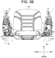
- FIG. 3A and FIG. 3B are front views illustrating the schematic configuration of the pair of operation devices included in the work machine 100.
- FIG. 3B is a view showing a state in which the posture of the pair of operation devices 1 has been changed from the state shown in FIG. 3A .
- FIG. 3A is a view in which the pair of operation devices 1 are in the narrowed state.
- FIG. 3B is a view in which the pair of operation devices 1 are in the expanded state.
- FIG. 3A and FIG. 3B also show members existing around the pair of operation devices 1 for ease of understanding.
- a cover 2b that covers a part of the members constituting the operation device 1 (see FIG. 1 , FIG. 2A, and FIG. 2B ) is removed.
- the operation devices 1 disposed on the left and right sides of the seat 102c are disposed on the hood 102d.
- Each of the left and right operation devices 1 includes a lever stand 2, a lever stand support portion 3, a base portion 4, and a holding plate 5.
- the left and right operation devices 1 have the same structure.
- the structures of the left and right operation devices 1 specifically have slight differences in the shapes, arrangements, and orientations of the constituent members. However, the design concept of the left and right operation devices 1 and the functions of the left and right operation devices 1 are the same. For this reason, the description of the structure of the operation device 1 will be made with reference to the operation device 1 disposed on the left side as a representative example. The description of the structure of the operation device 1 disposed on the right side will be omitted if not required.
- FIG. 4A and FIG. 4B are perspective views showing a schematic configuration of the operation device 1 on the left side.
- FIG. 4B is a view showing a state in which the posture of the lever stand 2 has been changed from a first posture shown in FIG. 4A to a second posture. The first posture and the second posture will be described later.
- FIG. 1 , FIG. 2A , FIG. 2B , FIG. 3A , and FIG. 3B show a state in which the lever stand 2 is in the first posture.
- the lever stand 2 is disposed on a side (left side in this example) of the seat 102c and has an operation lever 2a.
- the operation lever 2a is disposed on the top of the lever stand 2.
- the operation lever 2a is a portion that is actually operated by an operator who sits on the seat 102c and operates the work device 103. Hydraulic control of the hydraulic actuator is performed by an operation of the operation lever 2a.
- the first posture is a posture in which the operation lever 2a can be operated.
- the first posture is a condition required for performing an operation using the operation lever 2a, and the operation by the operation lever 2a may not be performed in the first posture.
- the second posture is a posture in which the operation lever 2a cannot be operated.
- the second posture widely includes postures in which the operation lever 2a cannot be operated, and the posture shown in FIG. 4B is merely an example of the second posture. In the present embodiment, it is possible to easily switch the posture of the operation lever 2a between the first posture and the second posture by raising and lowering the lever stand 2.
- the lever stand 2 further has a stand frame 21 below the operation lever 2a.
- the stand frame 21 is used for coupling with the lever stand support portion 3 and the like.
- the stand frame 21 is composed of a plurality of members.
- the stand frame 21 may be composed of a single member in some cases.
- the cutoff lever 8 is supported by the stand frame 21. Specifically, the cutoff lever 8 is pivotable with respect to the stand frame 21 between an upper limit position and a lower limit position. In a state in which the cutoff lever 8 is lowered (for example, the state shown in FIG. 1 and FIG. 4A , and the like), the cutoff lever 8 extending forward prevents the operator from exiting the work machine 100. When the cutoff lever 8 is raised to the upper limit position, pilot pressure is cut off, and the operation of the work machine 100 is disabled. The cutoff lever 8 in the upper limit position cannot be pivoted further upward with respect to the stand frame 21. When the cutoff lever 8 in the upper limit position is pulled upward, the front side of the lever stand 2 is lifted as described later.
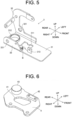
- FIG. 5 is a perspective view showing a schematic configuration of a lever stand support portion 3.
- the lever stand support portion 3 has a bottom plate 31, a left side plate 32, and a right side plate 33.
- the lever stand support portion 3 is composed of a plurality of members.
- the lever stand support portion 3 may be composed of a single member in some cases.
- the bottom plate 31 has a rectangular plate shape extending in the front-rear direction.
- the bottom plate 31 has a central opening 311 penetrating in the up-down direction in the central portion. Further, the bottom plate 31 has a rear opening 312 penetrating in the up-down direction in the rear portion.
- the left side plate 32 is disposed at a left end portion of the bottom plate 31 and extends in the up-down direction.
- the left side plate 32 has a left side plate opening 321 penetrating in the left-right direction.
- the right side plate 33 is disposed at a right end portion of the bottom plate 31 and extends in the up-down direction.
- the right side plate 33 has a right side plate opening 331 penetrating in the left-right direction.
- the left side plate 32 and the right side plate 33 support a rear shaft portion 34 disposed at the rear portion thereof.
- the rear shaft portion 34 extends in the left-right direction.
- the rear shaft portion 34 is supported by the left side plate 32 and the right side plate 33 in a state in which a left end portion of the rear shaft portion 34 is inserted in the left side plate opening 321 and a right end portion of the rear shaft portion 34 is inserted in the right side plate opening 331.
- the rear shaft portion 34 is disposed behind the lever stand support portion 3, and pivotably supports the stand frame 21 of the lever stand 2. That is, the rear portion of the lever stand 2 is pivotably supported by the rear shaft portion 34. Since the rear portion of the lever stand 2 is supported by the rear shaft portion 34, the front portion of the lever stand 2 can be raised and lowered.
- the first posture shown in FIG. 4A is a state in which the front portion of the lever stand 2 is lowered.
- the second posture shown in FIG. 4B is a state in which, from the first posture shown in FIG. 4A , the front portion of the lever stand 2 is lifted and the lever stand 2 is pivoted about the rear shaft portion 34.
- FIG. 6 is a perspective view showing a schematic configuration of the base portion 4. As shown in FIG. 4A , FIG. 4B , and FIG. 6 , the base portion 4 has a rectangular flat plate shape. The base portion 4 is supported by the hood 102d in a state in which the base portion 4 is fixed to the hood 102d by fixing tools such as screws (see FIG. 3A and FIG. 3B ).
- the base portion 4 has a base opening 41 penetrating in the up-down direction in the central portion. Further, the base portion 4 includes a first convex portion 42 having a rectangular parallelepiped shape protruding upward on a side (specifically, the left side) of the base opening 41. In addition, the base portion 4 has a second convex portion 43 having a columnar shape protruding upward at the rear portion.
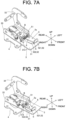
- FIG. 7A and FIG. 7B are schematic perspective views each showing a relationship between the lever stand support portion 3, the base portion 4, and a holding plate 5.
- FIG. 7B is a view showing a state in which the posture of a lever stand support portion 3 has been changed from a third posture shown in FIG. 7A to a fourth posture.
- the third posture is a posture in which the operation device 1 is in the narrowed state (see FIG. 2A and FIG. 3A ).
- the fourth posture is a posture in which the operation device 1 is in the expanded state (see FIG. 2B and FIG. 3B ).
- the operation lever 2a is disposed on an outer side in the left-right direction away from the seat 102c in the left-right direction than when the lever stand support portion 3 is in the third posture.
- the lever stand support portion 3 and the base portion 4 are superposed to each other in a state in which the lever stand support portion 3 is positioned above the base portion 4. More specifically, the lever stand support portion 3 and the base portion 4 are superposed to each other in the up-down direction with the first convex portion 42 of the base portion 4 being inserted in the central opening 311 of the lever stand support portion 3. Further, the lever stand support portion 3 and the base portion 4 are superposed to each other in the up-down direction with the second convex portion 43 of the base portion 4 being inserted in the rear opening 312 of the lever stand support portion 3.
- the lever stand support portion 3 and the base portion 4 are superposed to each other in the up-down direction in a state in which a lower end portion of a fixing tool B for attaching the right side plate 33 to the bottom plate 31 is inserted in the base opening 41.
- the base portion 4 supports the lever stand support portion 3 so that the lever stand support portion 3 is pivotable left and right. Since the lever stand support portion 3 supports the lever stand 2, the lever stand 2 is also pivotable left and right with respect to the base portion 4.
- the lever stand support portion 3 is provided so that the front portion of the lever stand support portion 3 is pivotable in the left-right direction about the second convex portion 43.
- the pivot range of the lever stand support portion 3 in the left-right direction is limited by the contact between the first convex portion 42 and the inner peripheral surface of the central opening 311. Note that, in the third posture shown in the FIG.
- the holding plate 5 has a plate shape extending in the front-rear direction, and the holding plate 5 is supported by the base portion 4.
- the holding plate 5 is fixed to the upper surface of the first convex portion 42 using the fixing tool B.
- the upper surface of the first convex portion 42 protrudes slightly above the upper surface of the bottom plate 31 through the central opening 311.
- the holding plate 5 is arranged above the bottom portion (bottom plate 31) of the lever stand support portion 3.
- the bottom portion of the lever stand support portion 3 is provided with an opening portion 311, and the holding plate 5 is supported by the base portion 4 through the opening portion 311. Since the holding plate 5 is configured to use the opening portion 311 as described above, the holding plate 5 supported by the base portion 4 can be disposed above the bottom portion of the lever stand support portion 3 without complicating the structure.
- the holding plate 5 and the lever stand support portion 3 hold a biasing member 6 that biases the lever stand support portion 3 into the third posture.
- a predetermined operation (details will be described later) is performed, it is possible to automatically bring the lever stand support portion 3 into the third posture and bring the operation device 1 into the narrowed state.
- the biasing member may be configured to bias the lever stand support portion 3 in a direction in which the lever stand support portion 3 becomes the fourth posture. In this case, when a predetermined operation is performed, it is possible to automatically bring the lever stand support portion 3 into the fourth posture and bring the operation device 1 into the expanded state.
- support portions 313 and 51 for supporting a support bar 7 extending in the left-right direction are erected on the upper surface of the bottom plate 31 and the upper surface of the plate body 5a of the holding plate 5.
- the biasing member 6 is composed of a compression coil spring. Since the support bar 7 is inserted through the compression coil spring 6, the compression coil spring 6 is supported by the support bar 7 in a state in which the compression coil spring 6 is between the two support portions 313 and 51.
- the holding plate 5 is fixed to the base portion 4.
- the lever stand support portion 3 is supported so that the lever stand support portion 3 is pivotable in the left-right direction with respect to the base portion 4. Therefore, the lever stand support portion 3 is pressed toward the seat 102c side (inward in the left-right direction) by the biasing force of the compression coil spring 6, and the lever stand support portion 3 becomes the third posture.
- the holding plate 5 has a holding portion 52 extending upward from the plate body 5a.
- the holding portion 52 functions to hold the lever stand 2 in the first posture (see FIG. 4A and the like).
- the lever stand 2 has a protruding portion 22 that is to be held by the holding portion 52 in the first posture.
- the protruding portion 22 is positioned at the front lower portion and held by the holding portion 52.
- the holding portion 52 includes a first holding portion 521 and a second holding portion 522 disposed adjacent to the first holding portion 521 in the left-right direction.
- the first holding portion 521 is disposed at a front end portion of the plate body 5a and extends upward and in the left-right direction.
- the first holding portion 521 is formed by bending the front side of the plate body 5a upward.
- the second holding portion 522 is disposed adjacent to the first holding portion 521 on the right side and extends upward and in the front-rear direction.
- the second holding portion 522 is formed by bending the front right side of the plate body 5a upward.
- a gap S is formed between the first holding portion 521 and the second holding portion 522 in the left-right direction.
- the holding portion 52 holds the protruding portion 22 by fitting the protruding portion 22 into the gap S.
- the protruding portion 22 includes a first protruding portion 221 and a second protruding portion 222 disposed on the outside of the first protruding portion 221 in the left-right direction.
- the second protruding portion 222 is disposed on the left side (the side away from the seat 102c) of the first protruding portion 221.
- the first protruding portion 221 and the second protruding portion 222 are spaced apart from each other in the left-right direction.
- Each of the first protruding portion 221 and the second protruding portion 222 has a flat plate shape extending in a direction parallel to the up-down direction.
- the lever stand support portion 3 is held in the fourth posture (see FIG. 3B ).
- the first protruding portion 221 needs to be present below, and the lever stand 2 is in the first posture.
- the width of the gap S between the first holding portion 521 and the second holding portion 522 is slightly larger than the thickness of the first protruding portion 221 having a flat plate shape. Therefore, the first protruding portion 221 fitted into the gap S between the first holding portion 521 and the second holding portion 522 is held between the first holding portion 521 and the second holding portion 522.
- the lever stand support portion 3 is held in the third posture (see FIG. 3A ).
- the second protruding portion 222 needs to be present below, and the lever stand 2 is in the first posture.
- the width of the gap S between the first holding portion 521 and the second holding portion 522 is slightly larger than the thickness of the second protruding portion 222 having a flat plate shape. Therefore, the second protruding portion 222 fitted into the gap S between the first holding portion 521 and the second holding portion 522 is held between the first holding portion 521 and the second holding portion 522.
- the biasing member (compression coil spring ) 6 biases the lever stand support portion 3 in the direction in which the lever stand support portion 3 becomes the third posture (posture to become the narrowed state). Therefore, by holding the first protruding portion 221 between the first holding portion 521 and the second holding portion 522, the lever stand support portion 3 is held in the fourth posture against the biasing force of the biasing member 6.
- the lever stand support portion 3 can be pivoted in the left-right direction to select the third posture or the fourth posture by pivoting the lever stand 2 from the first posture to the second posture. Further, the holding plate 5 holds, in the third posture or the fourth posture, the lever stand support portion 3 supporting the lever stand 2 in the first posture.
- the direction of pivot of the lever stand 2 from the first posture to the second posture is upward.
- the second posture is a posture in which the holding plate 5 releases the locked state in which the lever stand 2 is held in the first posture.
- the second posture is also a posture in which the operation lever 2a cannot be operated.
- the lever stand 2 when the lever stand 2 is in the first posture, it is possible to release the holding (locked state) of the lever stand 2 by the holding plate 5 by slightly pulling up the lever (specifically, the cutoff lever 8). After the lock state is easily released, it is possible to easily select the third posture or the fourth posture by moving the lever stand support portion 3 in the left-right direction together with the lever stand 2. Further, after selecting one of the third posture and the fourth posture, it is possible to easily fix the posture of the lever stand support portion 3 to the third posture or the fourth posture by lowering the pulled lever to return the lever stand 2 back to the first posture. That is, according to the present embodiment, it is possible to switch the operation device 1 between the expanded state and the narrowed state by a simple operation.
- the operation device 1 is in the narrowed state as shown in FIG. 2A and FIG. 3B .
- the operator When the operator performs work while sitting on the seat 102c of the work machine 100, the operator usually switches the state of the operation device 1 into the expanded state in order to perform the work in a comfortable posture.
- the front portion of the lever stand 2 in the first posture is lifted and the holding (locking) of the second protruding portion 222 by the first holding portion 521 and the second holding portion 522 is released. That is, the lever stand 2 becomes the second posture and the lever stand support portion 3 supporting the lever stand 2 becomes pivotable in the left-right direction.
- the operation of pulling up the cutoff lever 8 may be performed by a minimum pull-up amount capable of releasing the holding (locking) by the holding plate 5.
- the lever stand support portion 3 When the lock is released, the lever stand support portion 3 is automatically pivoted inward in the left-right direction together with the lever stand 2 to become the third posture by the biasing force of the compression coil spring 6. After this automatic movement, the operator lowers the cutoff lever 8 to bring the lever stand 2 into the first posture. Accordingly, the second protruding portion 222 is held between the first holding portion 521 and the second holding portion 522, and locking of the movement of the lever stand 2 by the holding plate 5 is completed. By performing this operation on the left and right operation devices 1, it is possible to bring the operation devices 1 into the narrowed state.
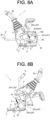
- FIG. 8A and FIG. 8B are views explaining a lifting operation of the lever stand 2.
- FIG. 8A is a side view of the left side operation device 1 as viewed from the left side surface.
- the lever stand 2 is in the first posture and is locked by the holding plate 5.
- the lever stand 2 is in the second posture and is pulled up by the maximum permissible amount.
- the lever stand 2 has a cam plate 23 on a side surface (specifically, a left side surface).
- the cam plate 23 is provided with a cam groove 231 into which a cam pin 322 fixed to the left side plate 32 of the lever stand support portion 3 is inserted.
- the cam groove 231 is S-shaped, and can be regarded as being divided into three portions of a first groove 231a, a second groove 231b, and a third groove 231c.
- the cam pin 322 When the lever stand 2 is in the first posture, the cam pin 322 is in the first groove 231a located at the rear end of the cam groove 231. In the first posture, the biasing force of the tension spring 9 of which one end is attached to the left side plate 32 and the other end is attached to the cam plate 23 is applied to keep the the cam pin 322 being inserted in the first groove 231a. Therefore, the lever stand 2 is maintained in the first posture when an external force for lifting the front portion of the lever stand 2 is not applied.
- the cam plate 23 included in the lever stand 2 also moves against the biasing force of the tension spring 9.
- the cam pin 322 comes out of the first groove 231a and enters the second groove 231b.
- the biasing force of the gas spring 10 assists the force for lifting the lever stand 2.
- the operator can easily lift the lever stand 2.
- one end of the gas spring 10 is attached to the right side plate 33 and the other end thereof is attached to a side portion of the lever stand 2 (see FIG. 4A and FIG. 4B , etc.). Both end portions of the gas spring 10 are attached to respective parts so that the both end portions are pivotable in a vertical plane. The gas spring 10 expands as the lever stand 2 is lifted.
- the lever stand 2 can be stably and easily moved up and down. Further, the lever stand 2 can be easily pivoted by the gas spring 10.
- An exemplary operation device of the present invention may be a configuration (first configuration) including a lever stand that is disposed on a side of a seat and has an operation lever; a lever stand support portion that supports the lever stand so that the lever stand is pivotable up and down; a base portion that is disposed below the lever stand support portion and supports the lever stand support portion so that the lever stand support portion is pivotable left and right; and a holding plate that is supported by the base portion and disposed above a bottom portion of the lever stand support portion; wherein, when the lever stand is pivoted from the first posture to the second posture, the lever stand support portion is made pivotable in a left-right direction to select a third posture or a fourth posture; and the holding plate holds, in the third posture or the fourth posture, the lever stand support portion supporting the lever stand in the first posture.
- the operation device of the first configuration may have a configuration (second configuration) in which: the first posture is a posture in which the operation lever can be operated, and the second posture is a posture in which the operation lever cannot be operated.
- the operation device of the first or second configuration may have a configuration (third configuration) in which: a bottom portion of the lever stand support portion is provided with an opening portion, and the holding plate is supported by the base portion through the opening portion.
- the operation device of any one of the first to third configurations may have a configuration (fourth configuration) in which: the holding plate has a holding portion extending upward from a plate body, and the lever stand has a protruding portion held by the holding portion 52 in the first posture.
- the operation device of the fourth configuration may have a configuration (fifth configuration) in which: the holding portion includes a first holding portion and a second holding portion disposed adjacent to the first holding portion in a left-right direction, the protruding portion includes a first protruding portion and a second protruding portion disposed on an outside of the first protruding portion in the left-right direction, when the first protruding portion is held between the first holding portion and the second holding portion, the lever stand support portion is held in the fourth posture, and when the second protruding portion is held between the first holding portion and the second holding portion, the lever stand support portion is held in the third posture.
- the operation device of any one of the first to fifth configurations may have a configuration (sixth configuration) in which: when the lever stand support portion is in the fourth posture, the operation lever is disposed on an outer side in the left-right direction away from the seat in the left-right direction than when the lever stand support portion is in the third posture, and the holding plate and the lever stand support portion hold a biasing member that biases the lever stand support portion in a direction in which the lever stand support portion is brought into the third posture.
- the operation device of the sixth configuration may have a configuration (seventh configuration) in which: by holding the first protruding portion between the first holding portion and the second holding portion, the lever stand support portion is held in the fourth posture against the biasing force of the biasing member.
- An exemplary work machine of the present invention may have a configuration (eighth configuration) including the operation device according to any one of the first to seventh configurations; and the seat.
Landscapes
- Engineering & Computer Science (AREA)
- Mining & Mineral Resources (AREA)
- Civil Engineering (AREA)
- General Engineering & Computer Science (AREA)
- Structural Engineering (AREA)
- Component Parts Of Construction Machinery (AREA)
- Mechanical Control Devices (AREA)
Abstract
Description
- The present invention relates to an operation device and a work machine.
- In the related art, an expansion-type remote control valve unit is known in which remote control valve units on both left and right sides of a seat, on which an operator sits, are configured to be expandable to the left and right (for example, see Patent Document 1).
- In the expansion-type remote control valve unit of
Patent Document 1, a rotary drive body is provided at a rear portion or a rear side of the remote control valve unit. The remote control valve unit is rotated around the rotary drive body so that the front portion of the remote control valve unit is positioned outside with respect to the rear portion of the remote control valve unit by a preset range. A lock mechanism is provided for locking the remote control valve unit rotated outward at a preset position. The lock mechanism includes a moving plate that rotates integrally with the remote control valve unit, and a support plate that supports the remote control valve unit from below. A lock hole is formed in one of the moving plate and the support plate, and a lock pin that is to be inserted into the lock hole is provided in the other of the moving plate and the support plate. When the lock pin is inserted into the lock hole, the rotation of the remote control valve unit is locked. - Patent Document 1:
Japanese Unexamined Patent Application Publication No. 2020-45744 - In
Patent Document 1, the remote control valve unit is configured such that a front portion thereof is rotatable up and down about a rear portion or a rear side thereof. The lock mechanism is configured to be operable in a state in which the front portion of the remote control valve unit is moved upward. That is, in the related art, in order to make the lock mechanism operable, it is firstly required to lift the remote control valve unit. Then, after the lock mechanism is made operable by lifting the remote control valve unit, the lock mechanism is unlocked by pulling out the lock pin from the lock hole. After the lock mechanism is unlocked, the remote control valve unit can be rotated. - In the prier art configuration, there is a possibility that a user may feel that there is a lot of operations to rotate the remote control valve unit locked by the lock mechanism. That is, there is a possibility that the user desires an extension-type operation device with better operability.
- In view of the above, an object of the present invention is to provide a technique capable of improving the operability of an expansion-type operation device.
- An exemplary operation device of present invention includes:
- a lever stand that is disposed on a side of a seat and has an operation lever; a lever stand support portion that supports the lever stand so that the lever stand is pivotable up and down; a base portion that is disposed below the lever stand support portion and supports the lever stand support portion so that the lever stand support portion is pivotable left and right; and
- a holding plate that is supported by the base portion and disposed above a bottom portion of the lever stand support portion. When the lever stand is pivoted from the first posture to the second posture, the lever stand support portion is made pivotable in a left-right direction to select a third posture or a fourth posture. The holding plate holds, in the third posture or the fourth posture, the lever stand support portion supporting the lever stand in the first posture.
- According to the exemplary present invention, the operability of the expansion-type operation device can be improved.
-
-
FIG. 1 is a side view illustrating a schematic configuration of a work machine. -
FIG. 2A is a top view illustrating a schematic configuration of a swing body included in the work machine. -
FIG. 2B is a view showing a state in which the posture of an operation device has been changed from the state shown inFIG. 2A . -
FIG. 3A is a front view illustrating a schematic configuration of a pair of operation devices included in the work machine. -
FIG. 3B is a view showing a state in which the posture of the pair of operation devices have been changed from the state shown inFIG. 3A . -
FIG. 4A is a perspective view showing a schematic configuration of the operation device on a left side. -
FIG. 4B is a view showing a state in which the posture of a lever stand has been changed from a first posture shown inFIG. 4A to a second posture. -
FIG. 5 is a perspective view showing a schematic configuration of a lever stand support portion. -
FIG. 6 is a perspective view illustrating a schematic configuration of a base portion. -
FIG. 7A is a schematic perspective view showing a relationship between the lever stand support portion, the base portion, and a holding plate. -
FIG. 7B is a view showing a state in which the posture of the lever stand support portion has been changed from a third posture shown inFIG. 7A to a fourth posture. -
FIG. 8A is a view explaining a lifting operation of the lever stand. -
FIG. 8B is a view explaining a lifting operation of the lever stand. - Hereinafter, an exemplary embodiment of the present invention will be described in detail with reference to the drawings. In the drawings, the same or corresponding parts are denoted by the same reference characters, and a description thereof will not be repeated unless otherwise required.
-
FIG. 1 is a side view illustrating a schematic configuration of awork machine 100 according to an embodiment of the present invention. Thework machine 100 includes anoperation device 1 according to the embodiment of the present invention. Theoperation device 1 is a device for operating thework machine 100. In detail, thework machine 100 is a hydraulic excavator. Theoperation device 1 is a device for operating the hydraulic excavator. Note that the work machine to which the operation device of the present invention is applied is not limited to a hydraulic excavator. The operation device of the present invention may be applied to another work machine such as a wheel loader and a bulldozer, etc. - As shown in
FIG. 1 , thework machine 100 includes a travelingbody 101, aswing body 102, and awork device 103. - Here, directions in this specification are defined as follows. A direction in which the traveling
body 101 travels straight ahead is defined as a front-rear direction, and one side in the front-rear direction is defined as "front" and the other side in the front-rear direction is defined as "rear." In this specification, the side of the travelingbody 101 to which ablade 104 is attached is referred to as "front". A lateral direction perpendicular to the front-rear direction is defined as a left-right direction. In this specification, a left side and a right side when viewed from the rear to the front are referred to as "left" and "right", respectively. Further, a gravity direction perpendicular to the front-rear direction and the left-right direction is defined as an up-down direction, and an upstream side of the gravity direction is defined as "up" and a downstream side thereof is defined as "down." In the present specification, a plane parallel to the up-down direction may be referred to as a vertical plane. Note that these directions are merely names used for the purpose of illustration, and are not intended to limit the actual positional relationship and directions. - The traveling
body 101 enables thework machine 100 to travel by itself. Specifically, the travelingbody 101 includes a pair ofcrawlers 101b disposed on the left and right of a travelingbody frame 101a. Eachcrawler 101b is driven by a travelingmotor 101c composed of a hydraulic motor. When the pair of left andright crawlers 101b are simultaneously driven in the same direction, the travelingbody 101 travels straight forward or rearward. Which direction (forward or rearward) the travelingbody 101 moves is determined by the rotation direction of the travelingmotor 101c. When the pair of left andright crawlers 101b are independently driven, the travelingbody 101 turns left or right. - Note that although the traveling
body 101 of the present embodiment is a crawler type, the traveling body is not limited to the crawler type and may be a wheel type or the like. Further, in the present embodiment, a front portion of the travelingbody 101 is provided with ablade 104 that is movable up and down by extension and contraction of ablade cylinder 104a composed of a hydraulic cylinder. By using theblade 104, thework machine 100 can perform ground leveling work. Note that theblade 104 may not be provided. - The
swing body 102 is swingably mounted on the travelingbody 101. Specifically,swing body 102 has aswing body frame 102a and a swing table 102b fixed to theswing body frame 102a. The swing table 102b is disposed between the pair of left andright crawlers 101b when seen in a plan view. The swing table 102b is rotatably supported by the travelingbody frame 101a. The swing table 102b is driven by a swing motor (not shown) composed of a hydraulic motor and swings about a central axis extending in the up-down direction. Theswing body frame 102a can swing to the right and left together with the swing table 102b. - In the present specification, directions are expressed on the assumption that the
swing body 102 is directed forward as shown inFIG. 1 . - A seat (driver's seat) 102c on which an operator who operates the
work machine 100 sits is disposed on theswing body 102. That is, thework machine 100 includes theseat 102c. An operator sitting on theseat 102c operates various operation levers and pedals provided in the vicinity of theseat 102c. The various operation levers include anoperation lever 2a included in theoperation device 1. - The
seat 102c is supported by a hood (prime mover cover) 102d that covers a prime mover mounted on theswing body frame 102a. The prime mover drives a hydraulic pump (not shown) that supplies pressure oil to a hydraulic actuator mounted on thework machine 100. The prime mover may be, for example, at least one of an engine and an electric motor. The hydraulic actuator includes various hydraulic motors and hydraulic cylinders. - The
work device 103 includes aboom 103a, anarm 103b, and abucket 103c. Thework device 103 moves theboom 103a, thearm 103b, and thebucket 103c simultaneously or independently to perform excavation work of soil and sand or the like. Note that thebucket 103c may be replaced with another work tool such as a breaker used when a demolishing work is performed, for example. - One end of the
boom 103a is supported by theboom bracket 103d and theboom 103a is rotatable in a vertical plane by aboom cylinder 103e that is provided to be expandable and contractible. One end of thearm 103b is supported by the other end of theboom 103a and thearm 103b is rotatable in a vertical plane by anarm cylinder 103f that is provided to be expandable and contractible. One end of thebucket 103c is supported by the other end of thearm 103b and thebucket 103c is rotatable in a vertical plane by abucket cylinder 103g that is provided to be expandable and contractible. InFIG. 1 , theboom 103a, thearm 103b, and thebucket 103c are each provided to be rotatable about a central shaft extending in the left-right direction. - The
work device 103 is attached to aninstallation portion 102e of theswing body 102. Theinstallation portion 102e protrudes forward from a front end portion of theswing body 102. Theboom bracket 103d is supported by theinstallation portion 102e so as to be rotatable about a central axis extending in the up-down direction. Theboom bracket 103d is connected to a swing cylinder (not shown) disposed on theswing body 102 so as to be extendable and contractible in the front-rear direction. Theboom bracket 103d is pivoted counterclockwise or clockwise by expansion and contraction of the swing cylinder. That is, by the action the swing cylinder, it is possible to swing thework device 103 counterclockwise or clockwise. - An operator sitting on the
seat 102c can control various hydraulic actuators and the like by operating theoperation device 1 and the like to perform work using thework device 103. -
FIG. 2A and FIG. 2B are top views illustrating a schematic configuration of theswing body 102 included in thework machine 100.FIG. 2B is a view showing a state in which the posture of theoperation device 1 has been changed from the state shown inFIG. 2A . As shown inFIG. 2A and FIG. 2B , in thework machine 100,operation devices 1 for operating thework machine 100 are arranged on the left side and the right side of theseat 102c. The pair of left andright operation devices 1 are provided so that a distance therebetween in the left-right direction can be changed. - In the state shown in
FIG. 2A , the pair of left andright operation devices 1 are in the width of theswing body 102 in the left-right direction, and do not protrude from theswing body 102 in the left-right direction. On the other hand, in the state shown inFIG. 2B , the pair of left andright operation devices 1 are not in the width of theswing body 102 in the left-right direction, and parts of theoperation devices 1 protrude from theswing body 102 in the left-right direction. It can be said that, with reference to the state shown inFIG. 2A , the width of the pair of left andright operation devices 1 in the left-right direction can be expanded by changing the state shown inFIG. 2A to the state shown inFIG. 2B . That is, it can be said that theoperation device 1 included in thework machine 100 is an expansion-type operation device. - Hereinafter, for the sake of convenience, the state shown in
FIG. 2A in which the distance between the pair ofoperation devices 1 in the left-right direction is narrowed may be referred to as a narrowed state. Further, the state in shown inFIG. 2B which the distance between the pair ofoperation devices 1 in the left-right direction is expanded may be referred to as an expanded state. The narrowed state shown inFIG. 2A is a state convenient for thework machine 100 to pass through a narrow place. An example of passing through a narrow place may be, for example, passing through a frontage in a case where indoor demolition work is performed by thework machine 100. The expanded state shown inFIG. 2B is a state convenient for performing work using thework device 103. In the expanded state, the possibility that an operator sitting on theseat 102c feels tight due to the presence of theoperation device 1 can be reduced. - In the present embodiment, each of the pair of
operation devices 1 can select only two postures, that is, a posture for the narrowed state and a posture for the expanded state. However, this is merely an example. Each of the pair ofoperation devices 1 can select more than two postures to change the width in the left-right direction. - Next, the structure of the above-described operation device 1 (expansion-type operation device) having an expansion function of expanding the width in the left-right direction will be described in detail.
-
FIG. 3A andFIG. 3B are front views illustrating the schematic configuration of the pair of operation devices included in thework machine 100.FIG. 3B is a view showing a state in which the posture of the pair ofoperation devices 1 has been changed from the state shown inFIG. 3A . Specifically,FIG. 3A is a view in which the pair ofoperation devices 1 are in the narrowed state.FIG. 3B is a view in which the pair ofoperation devices 1 are in the expanded state. Note thatFIG. 3A andFIG. 3B also show members existing around the pair ofoperation devices 1 for ease of understanding. Further, inFIG. 3A andFIG. 3B , acover 2b that covers a part of the members constituting the operation device 1 (seeFIG. 1 ,FIG. 2A, and FIG. 2B ) is removed. - As shown in
FIG. 3A andFIG. 3B , theoperation devices 1 disposed on the left and right sides of theseat 102c are disposed on thehood 102d. Each of the left andright operation devices 1 includes alever stand 2, a leverstand support portion 3, abase portion 4, and a holdingplate 5. The left andright operation devices 1 have the same structure. - Note that the structures of the left and
right operation devices 1 specifically have slight differences in the shapes, arrangements, and orientations of the constituent members. However, the design concept of the left andright operation devices 1 and the functions of the left andright operation devices 1 are the same. For this reason, the description of the structure of theoperation device 1 will be made with reference to theoperation device 1 disposed on the left side as a representative example. The description of the structure of theoperation device 1 disposed on the right side will be omitted if not required. -
FIG. 4A andFIG. 4B are perspective views showing a schematic configuration of theoperation device 1 on the left side.FIG. 4B is a view showing a state in which the posture of thelever stand 2 has been changed from a first posture shown inFIG. 4A to a second posture. The first posture and the second posture will be described later. Note thatFIG. 1 ,FIG. 2A ,FIG. 2B ,FIG. 3A , andFIG. 3B show a state in which thelever stand 2 is in the first posture. - The
lever stand 2 is disposed on a side (left side in this example) of theseat 102c and has anoperation lever 2a. Theoperation lever 2a is disposed on the top of thelever stand 2. Theoperation lever 2a is a portion that is actually operated by an operator who sits on theseat 102c and operates thework device 103. Hydraulic control of the hydraulic actuator is performed by an operation of theoperation lever 2a. - The first posture is a posture in which the
operation lever 2a can be operated. The first posture is a condition required for performing an operation using theoperation lever 2a, and the operation by theoperation lever 2a may not be performed in the first posture. The second posture is a posture in which theoperation lever 2a cannot be operated. The second posture widely includes postures in which theoperation lever 2a cannot be operated, and the posture shown inFIG. 4B is merely an example of the second posture. In the present embodiment, it is possible to easily switch the posture of theoperation lever 2a between the first posture and the second posture by raising and lowering thelever stand 2. - The lever stand 2 further has a
stand frame 21 below theoperation lever 2a. Thestand frame 21 is used for coupling with the lever standsupport portion 3 and the like. In the present embodiment, thestand frame 21 is composed of a plurality of members. However, thestand frame 21 may be composed of a single member in some cases. - The above-described
cover 2b (seeFIG. 1 and the like) is fixed to thestand frame 21. Therefore, thecover 2b can be considered as a part of thelever stand 2. In the present embodiment, thecutoff lever 8 is supported by thestand frame 21. Specifically, thecutoff lever 8 is pivotable with respect to thestand frame 21 between an upper limit position and a lower limit position. In a state in which thecutoff lever 8 is lowered (for example, the state shown inFIG. 1 andFIG. 4A , and the like), thecutoff lever 8 extending forward prevents the operator from exiting thework machine 100. When thecutoff lever 8 is raised to the upper limit position, pilot pressure is cut off, and the operation of thework machine 100 is disabled. Thecutoff lever 8 in the upper limit position cannot be pivoted further upward with respect to thestand frame 21. When thecutoff lever 8 in the upper limit position is pulled upward, the front side of thelever stand 2 is lifted as described later. - The lever
stand support portion 3 is disposed below thelever stand 2. The leverstand support portion 3 supports thelever stand 2 so that thelever stand 2 is pivotable up and down.FIG. 5 is a perspective view showing a schematic configuration of a leverstand support portion 3. As shown inFIG. 4A ,FIG. 4B , andFIG. 5 , the lever standsupport portion 3 has abottom plate 31, aleft side plate 32, and aright side plate 33. In the present embodiment, the lever standsupport portion 3 is composed of a plurality of members. However, the lever standsupport portion 3 may be composed of a single member in some cases. - The
bottom plate 31 has a rectangular plate shape extending in the front-rear direction. Thebottom plate 31 has acentral opening 311 penetrating in the up-down direction in the central portion. Further, thebottom plate 31 has arear opening 312 penetrating in the up-down direction in the rear portion. Theleft side plate 32 is disposed at a left end portion of thebottom plate 31 and extends in the up-down direction. Theleft side plate 32 has a left side plate opening 321 penetrating in the left-right direction. Theright side plate 33 is disposed at a right end portion of thebottom plate 31 and extends in the up-down direction. Theright side plate 33 has a right side plate opening 331 penetrating in the left-right direction. - As shown in
FIG. 4A andFIG. 4B , theleft side plate 32 and theright side plate 33 support arear shaft portion 34 disposed at the rear portion thereof. Therear shaft portion 34 extends in the left-right direction. Therear shaft portion 34 is supported by theleft side plate 32 and theright side plate 33 in a state in which a left end portion of therear shaft portion 34 is inserted in the left side plate opening 321 and a right end portion of therear shaft portion 34 is inserted in the rightside plate opening 331. - The
rear shaft portion 34 is disposed behind the lever standsupport portion 3, and pivotably supports thestand frame 21 of thelever stand 2. That is, the rear portion of thelever stand 2 is pivotably supported by therear shaft portion 34. Since the rear portion of thelever stand 2 is supported by therear shaft portion 34, the front portion of thelever stand 2 can be raised and lowered. The first posture shown inFIG. 4A is a state in which the front portion of thelever stand 2 is lowered. The second posture shown inFIG. 4B is a state in which, from the first posture shown inFIG. 4A , the front portion of thelever stand 2 is lifted and thelever stand 2 is pivoted about therear shaft portion 34. - The
base portion 4 is disposed below the lever standsupport portion 3.FIG. 6 is a perspective view showing a schematic configuration of thebase portion 4. As shown inFIG. 4A ,FIG. 4B , andFIG. 6 , thebase portion 4 has a rectangular flat plate shape. Thebase portion 4 is supported by thehood 102d in a state in which thebase portion 4 is fixed to thehood 102d by fixing tools such as screws (seeFIG. 3A andFIG. 3B ). - The
base portion 4 has abase opening 41 penetrating in the up-down direction in the central portion. Further, thebase portion 4 includes a firstconvex portion 42 having a rectangular parallelepiped shape protruding upward on a side (specifically, the left side) of thebase opening 41. In addition, thebase portion 4 has a secondconvex portion 43 having a columnar shape protruding upward at the rear portion. -
FIG. 7A and FIG. 7B are schematic perspective views each showing a relationship between the lever standsupport portion 3, thebase portion 4, and a holdingplate 5.FIG. 7B is a view showing a state in which the posture of a leverstand support portion 3 has been changed from a third posture shown inFIG. 7A to a fourth posture. In the present embodiment, the third posture is a posture in which theoperation device 1 is in the narrowed state (seeFIG. 2A andFIG. 3A ). The fourth posture is a posture in which theoperation device 1 is in the expanded state (seeFIG. 2B andFIG. 3B ). When the lever standsupport portion 3 is in the fourth posture, theoperation lever 2a is disposed on an outer side in the left-right direction away from theseat 102c in the left-right direction than when the lever standsupport portion 3 is in the third posture. - As shown in
FIG. 7A and FIG. 7B , the lever standsupport portion 3 and thebase portion 4 are superposed to each other in a state in which the lever standsupport portion 3 is positioned above thebase portion 4. More specifically, the lever standsupport portion 3 and thebase portion 4 are superposed to each other in the up-down direction with the firstconvex portion 42 of thebase portion 4 being inserted in thecentral opening 311 of the lever standsupport portion 3. Further, the lever standsupport portion 3 and thebase portion 4 are superposed to each other in the up-down direction with the secondconvex portion 43 of thebase portion 4 being inserted in therear opening 312 of the lever standsupport portion 3. Note that, in the present embodiment, the lever standsupport portion 3 and thebase portion 4 are superposed to each other in the up-down direction in a state in which a lower end portion of a fixing tool B for attaching theright side plate 33 to thebottom plate 31 is inserted in thebase opening 41. - The
base portion 4 supports the lever standsupport portion 3 so that the lever standsupport portion 3 is pivotable left and right. Since the lever standsupport portion 3 supports thelever stand 2, thelever stand 2 is also pivotable left and right with respect to thebase portion 4. In detail, the lever standsupport portion 3 is provided so that the front portion of the lever standsupport portion 3 is pivotable in the left-right direction about the secondconvex portion 43. The pivot range of the lever standsupport portion 3 in the left-right direction is limited by the contact between the firstconvex portion 42 and the inner peripheral surface of thecentral opening 311. Note that, in the third posture shown in theFIG. 7A , the left side surface of the firstconvex portion 42 and the inner peripheral surface on the left side of thecentral opening 311 contact with each other, and the lever standsupport portion 3 cannot pivot further to the right (inward in the left-right direction). Further, in the fourth posture shown in theFIG. 7B , the right side surface of the firstconvex portion 42 and the inner peripheral surface on the right side of thecentral opening 311 contact with each other, and the lever standsupport portion 3 cannot pivot further to the left (outward in the left-right direction). - As shown in
FIG. 7A and FIG. 7B , the holdingplate 5 has a plate shape extending in the front-rear direction, and the holdingplate 5 is supported by thebase portion 4. In detail, the holdingplate 5 is fixed to the upper surface of the firstconvex portion 42 using the fixing tool B. The upper surface of the firstconvex portion 42 protrudes slightly above the upper surface of thebottom plate 31 through thecentral opening 311. For this purpose, the holdingplate 5 is arranged above the bottom portion (bottom plate 31) of the lever standsupport portion 3. In the present embodiment, the bottom portion of the lever standsupport portion 3 is provided with anopening portion 311, and the holdingplate 5 is supported by thebase portion 4 through theopening portion 311. Since the holdingplate 5 is configured to use theopening portion 311 as described above, the holdingplate 5 supported by thebase portion 4 can be disposed above the bottom portion of the lever standsupport portion 3 without complicating the structure. - In the present embodiment, the holding
plate 5 and the lever standsupport portion 3 hold a biasingmember 6 that biases the lever standsupport portion 3 into the third posture. By providing the biasingmember 6 described above, when a predetermined operation (details will be described later) is performed, it is possible to automatically bring the lever standsupport portion 3 into the third posture and bring theoperation device 1 into the narrowed state. - Note that the biasing member may be configured to bias the lever stand
support portion 3 in a direction in which the lever standsupport portion 3 becomes the fourth posture. In this case, when a predetermined operation is performed, it is possible to automatically bring the lever standsupport portion 3 into the fourth posture and bring theoperation device 1 into the expanded state. - Specifically,
support portions support bar 7 extending in the left-right direction are erected on the upper surface of thebottom plate 31 and the upper surface of theplate body 5a of the holdingplate 5. The biasingmember 6 is composed of a compression coil spring. Since thesupport bar 7 is inserted through thecompression coil spring 6, thecompression coil spring 6 is supported by thesupport bar 7 in a state in which thecompression coil spring 6 is between the twosupport portions - As described above, the holding
plate 5 is fixed to thebase portion 4. On the other hand, the lever standsupport portion 3 is supported so that the lever standsupport portion 3 is pivotable in the left-right direction with respect to thebase portion 4. Therefore, the lever standsupport portion 3 is pressed toward theseat 102c side (inward in the left-right direction) by the biasing force of thecompression coil spring 6, and the lever standsupport portion 3 becomes the third posture. In order to bring the lever standsupport portion 3 into the fourth posture shown inFIG. 7B , it is necessary to push the lever standsupport portion 3 to a side away from theseat 102c (outward in the left-right direction) against the biasing force of thecompression coil spring 6. - For example, as shown in
FIG. 7A and FIG. 7B , the holdingplate 5 has a holding portion 52 extending upward from theplate body 5a. The holding portion 52 functions to hold thelever stand 2 in the first posture (seeFIG. 4A and the like). As shown in theFIG. 4A , etc., thelever stand 2 has a protruding portion 22 that is to be held by the holding portion 52 in the first posture. When thelever stand 2 is in the first posture, the protruding portion 22 is positioned at the front lower portion and held by the holding portion 52. When the protruding portion 22 of thelever stand 2 is held by the holding portion 52 in a state in which the lever standsupport portion 3 is in the third posture, it is possible to bring theoperation device 1 into the narrowed state shown inFIG. 3A . When the protruding portion 22 of thelever stand 2 is held by the holding portion 52 in a state in which the lever standsupport portion 3 is in the fourth posture, it is possible to bring theoperation device 1 into the expanded state shown inFIG. 3B . - Specifically, the holding portion 52 includes a
first holding portion 521 and asecond holding portion 522 disposed adjacent to thefirst holding portion 521 in the left-right direction. Thefirst holding portion 521 is disposed at a front end portion of theplate body 5a and extends upward and in the left-right direction. In the present embodiment, thefirst holding portion 521 is formed by bending the front side of theplate body 5a upward. Thesecond holding portion 522 is disposed adjacent to thefirst holding portion 521 on the right side and extends upward and in the front-rear direction. In the present embodiment, thesecond holding portion 522 is formed by bending the front right side of theplate body 5a upward. A gap S is formed between thefirst holding portion 521 and thesecond holding portion 522 in the left-right direction. The holding portion 52 holds the protruding portion 22 by fitting the protruding portion 22 into the gap S. - Specifically, the protruding portion 22 includes a first protruding
portion 221 and a second protrudingportion 222 disposed on the outside of the first protrudingportion 221 in the left-right direction. In the example shown inFIG. 4A , the second protrudingportion 222 is disposed on the left side (the side away from theseat 102c) of the first protrudingportion 221. The first protrudingportion 221 and the second protrudingportion 222 are spaced apart from each other in the left-right direction. Each of the first protrudingportion 221 and the second protrudingportion 222 has a flat plate shape extending in a direction parallel to the up-down direction. - When the first protruding
portion 221 is held between thefirst holding portion 521 and thesecond holding portion 522, the lever standsupport portion 3 is held in the fourth posture (seeFIG. 3B ). In this case, the first protrudingportion 221 needs to be present below, and thelever stand 2 is in the first posture. The width of the gap S between thefirst holding portion 521 and thesecond holding portion 522 is slightly larger than the thickness of the first protrudingportion 221 having a flat plate shape. Therefore, the first protrudingportion 221 fitted into the gap S between thefirst holding portion 521 and thesecond holding portion 522 is held between thefirst holding portion 521 and thesecond holding portion 522. - When the second protruding
portion 222 is held between thefirst holding portion 521 and thesecond holding portion 522, the lever standsupport portion 3 is held in the third posture (seeFIG. 3A ). In this case, the second protrudingportion 222 needs to be present below, and thelever stand 2 is in the first posture. The width of the gap S between thefirst holding portion 521 and thesecond holding portion 522 is slightly larger than the thickness of the second protrudingportion 222 having a flat plate shape. Therefore, the second protrudingportion 222 fitted into the gap S between thefirst holding portion 521 and thesecond holding portion 522 is held between thefirst holding portion 521 and thesecond holding portion 522. - In the present embodiment, as described above, the biasing member (compression coil spring ) 6 biases the lever stand
support portion 3 in the direction in which the lever standsupport portion 3 becomes the third posture (posture to become the narrowed state). Therefore, by holding the first protrudingportion 221 between thefirst holding portion 521 and thesecond holding portion 522, the lever standsupport portion 3 is held in the fourth posture against the biasing force of the biasingmember 6. - As can be seen from the above description, in the present embodiment, the lever stand
support portion 3 can be pivoted in the left-right direction to select the third posture or the fourth posture by pivoting the lever stand 2 from the first posture to the second posture. Further, the holdingplate 5 holds, in the third posture or the fourth posture, the lever standsupport portion 3 supporting thelever stand 2 in the first posture. - In the present embodiment, the direction of pivot of the lever stand 2 from the first posture to the second posture is upward. Further, the second posture is a posture in which the holding
plate 5 releases the locked state in which thelever stand 2 is held in the first posture. In this embodiment, the second posture is also a posture in which theoperation lever 2a cannot be operated. - According to the configuration of the present embodiment, when the
lever stand 2 is in the first posture, it is possible to release the holding (locked state) of thelever stand 2 by the holdingplate 5 by slightly pulling up the lever (specifically, the cutoff lever 8). After the lock state is easily released, it is possible to easily select the third posture or the fourth posture by moving the lever standsupport portion 3 in the left-right direction together with thelever stand 2. Further, after selecting one of the third posture and the fourth posture, it is possible to easily fix the posture of the lever standsupport portion 3 to the third posture or the fourth posture by lowering the pulled lever to return thelever stand 2 back to the first posture. That is, according to the present embodiment, it is possible to switch theoperation device 1 between the expanded state and the narrowed state by a simple operation. - Next, the action and the like of the
operation device 1 having the above-described structure will be described in more detail. - First, it is assumed that when an operator sits on the
seat 102c, theoperation device 1 is in the narrowed state as shown inFIG. 2A andFIG. 3B . When the operator performs work while sitting on theseat 102c of thework machine 100, the operator usually switches the state of theoperation device 1 into the expanded state in order to perform the work in a comfortable posture. - At this time, the operator pulls up the
cutoff lever 8. Thus, the front portion of thelever stand 2 in the first posture is lifted and the holding (locking) of the second protrudingportion 222 by thefirst holding portion 521 and thesecond holding portion 522 is released. That is, thelever stand 2 becomes the second posture and the lever standsupport portion 3 supporting thelever stand 2 becomes pivotable in the left-right direction. The operation of pulling up thecutoff lever 8 may be performed by a minimum pull-up amount capable of releasing the holding (locking) by the holdingplate 5. - When the lock is released, the operator pivots the lever stand
support portion 3 together with thelever stand 2 outward in the left-right direction against the biasing force of thecompression coil spring 6 to bring the lever standsupport portion 3 into the fourth posture. Thereafter, the operator lowers thecutoff lever 8 to bring thelever stand 2 into the first posture. Accordingly, the first protrudingportion 221 is held between thefirst holding portion 521 and thesecond holding portion 522, and the locking of the movement of thelever stand 2 by the holdingplate 5 is completed. By performing this operation on the left andright operation devices 1, the expanded state of theoperation device 1 as shown inFIG. 2B andFIG. 3B can be obtained. - It may be desired to bring the
operation device 1 in the expanded state into the narrowed state when, for example, work is ended or it is necessary to pass through a narrow passage. In these cases, the operator pulls up thecutoff lever 8. Thus, the front portion of thelever stand 2 in the first posture is lifted and the holding (locking) of the first protrudingportion 221 by thefirst holding portion 521 and thesecond holding portion 522 is released. That is, thelever stand 2 becomes the second posture and the lever standsupport portion 3 supporting thelever stand 2 becomes pivotable in the left-right direction. - When the lock is released, the lever stand
support portion 3 is automatically pivoted inward in the left-right direction together with thelever stand 2 to become the third posture by the biasing force of thecompression coil spring 6. After this automatic movement, the operator lowers thecutoff lever 8 to bring thelever stand 2 into the first posture. Accordingly, the second protrudingportion 222 is held between thefirst holding portion 521 and thesecond holding portion 522, and locking of the movement of thelever stand 2 by the holdingplate 5 is completed. By performing this operation on the left andright operation devices 1, it is possible to bring theoperation devices 1 into the narrowed state. -
FIG. 8A and FIG. 8B are views explaining a lifting operation of thelever stand 2.FIG. 8A is a side view of the leftside operation device 1 as viewed from the left side surface. InFIG. 8A , thelever stand 2 is in the first posture and is locked by the holdingplate 5. InFIG. 8B , thelever stand 2 is in the second posture and is pulled up by the maximum permissible amount. - As shown in
FIG. 8A and FIG. 8B , thelever stand 2 has acam plate 23 on a side surface (specifically, a left side surface). Thecam plate 23 is provided with acam groove 231 into which acam pin 322 fixed to theleft side plate 32 of the lever standsupport portion 3 is inserted. Thecam groove 231 is S-shaped, and can be regarded as being divided into three portions of afirst groove 231a, asecond groove 231b, and athird groove 231c. - When the
lever stand 2 is in the first posture, thecam pin 322 is in thefirst groove 231a located at the rear end of thecam groove 231. In the first posture, the biasing force of thetension spring 9 of which one end is attached to theleft side plate 32 and the other end is attached to thecam plate 23 is applied to keep the thecam pin 322 being inserted in thefirst groove 231a. Therefore, thelever stand 2 is maintained in the first posture when an external force for lifting the front portion of thelever stand 2 is not applied. - When an external force for lifting the front portion of the
lever stand 2 is applied, thecam plate 23 included in thelever stand 2 also moves against the biasing force of thetension spring 9. When thecam plate 23 moves, thecam pin 322 comes out of thefirst groove 231a and enters thesecond groove 231b. Further, when thecam plate 23 moves, the biasing force of thegas spring 10 assists the force for lifting thelever stand 2. Thus, the operator can easily lift thelever stand 2. Note that one end of thegas spring 10 is attached to theright side plate 33 and the other end thereof is attached to a side portion of the lever stand 2 (seeFIG. 4A andFIG. 4B , etc.). Both end portions of thegas spring 10 are attached to respective parts so that the both end portions are pivotable in a vertical plane. Thegas spring 10 expands as thelever stand 2 is lifted. - When the action of lifting the
lever stand 2 is continued in a state in which thecam pin 322 is in thesecond groove 231b, thecam pin 322 enters athird groove 231c provided on the opposite side of thefirst groove 231a due to the movement of thecam plate 23. In this state, even if a force for lifting thelever stand 2 is applied, the movement of thecam plate 23 is obstructed by thecam pin 322, and thelever stand 2 cannot be lifted any further. - By providing the
cam plate 23 and thecam pin 322 as described above, thelever stand 2 can be stably and easily moved up and down. Further, thelever stand 2 can be easily pivoted by thegas spring 10. - The various technical features disclosed in the present specification can be modified in various ways without departing from the gist of the technical creation thereof. In addition, the multiple embodiments and variations described in the present specification may be combined to the extent possible.
- An exemplary operation device of the present invention may be a configuration (first configuration) including a lever stand that is disposed on a side of a seat and has an operation lever; a lever stand support portion that supports the lever stand so that the lever stand is pivotable up and down; a base portion that is disposed below the lever stand support portion and supports the lever stand support portion so that the lever stand support portion is pivotable left and right; and a holding plate that is supported by the base portion and disposed above a bottom portion of the lever stand support portion; wherein, when the lever stand is pivoted from the first posture to the second posture, the lever stand support portion is made pivotable in a left-right direction to select a third posture or a fourth posture; and the holding plate holds, in the third posture or the fourth posture, the lever stand support portion supporting the lever stand in the first posture.
- The operation device of the first configuration may have a configuration (second configuration) in which: the first posture is a posture in which the operation lever can be operated, and the second posture is a posture in which the operation lever cannot be operated.
- The operation device of the first or second configuration may have a configuration (third configuration) in which: a bottom portion of the lever stand support portion is provided with an opening portion, and the holding plate is supported by the base portion through the opening portion.
- The operation device of any one of the first to third configurations may have a configuration (fourth configuration) in which: the holding plate has a holding portion extending upward from a plate body, and the lever stand has a protruding portion held by the holding portion 52 in the first posture.
- The operation device of the fourth configuration may have a configuration (fifth configuration) in which: the holding portion includes a first holding portion and a second holding portion disposed adjacent to the first holding portion in a left-right direction, the protruding portion includes a first protruding portion and a second protruding portion disposed on an outside of the first protruding portion in the left-right direction, when the first protruding portion is held between the first holding portion and the second holding portion, the lever stand support portion is held in the fourth posture, and when the second protruding portion is held between the first holding portion and the second holding portion, the lever stand support portion is held in the third posture.
- The operation device of any one of the first to fifth configurations may have a configuration (sixth configuration) in which: when the lever stand support portion is in the fourth posture, the operation lever is disposed on an outer side in the left-right direction away from the seat in the left-right direction than when the lever stand support portion is in the third posture, and the holding plate and the lever stand support portion hold a biasing member that biases the lever stand support portion in a direction in which the lever stand support portion is brought into the third posture.
- The operation device of the sixth configuration may have a configuration (seventh configuration) in which: by holding the first protruding portion between the first holding portion and the second holding portion, the lever stand support portion is held in the fourth posture against the biasing force of the biasing member.
- An exemplary work machine of the present invention may have a configuration (eighth configuration) including the operation device according to any one of the first to seventh configurations; and the seat.
-
- 1 operation device
- 2 lever stand
- 2a operation lever
- 3 lever stand support portion
- 4 base portion
- 5 holding plate
- 5a plate body
- 6 compression coil spring (biasing member)
- 22 protruding portion
- 52 holding portion
- 100 work machine
- 102c seat
- 221 first protruding portion
- 222 second protruding portion
- 311 central opening (opening portion)
- 521 first holding portion
- 522 second holding portion
Claims (8)
- An operation device comprising:a lever stand that is disposed on a side of a seat and has an operation lever;a lever stand support portion that supports the lever stand so that the lever stand is pivotable up and down;a base portion that is disposed below the lever stand support portion and supports the lever stand support portion so that the lever stand support portion is pivotable left and right; anda holding plate that is supported by the base portion and disposed above a bottom portion of the lever stand support portion; wherein,when the lever stand is pivoted from the first posture to the second posture, the lever stand support portion is made pivotable in a left-right direction to select a third posture or a fourth posture; andthe holding plate holds, in the third posture or the fourth posture, the lever stand support portion supporting the lever stand in the first posture.
- The operation device according to claim 1, wherein:the first posture is a posture in which the operation lever can be operated, andthe second posture is a posture in which the operation lever cannot be operated.
- The operation device according to claim 1, wherein:a bottom portion of the lever stand support portion is provided with an opening portion, andthe holding plate is supported by the base portion through the opening portion.
- The operation device according to claim 1, wherein:the holding plate has a holding portion extending upward from a plate body, andthe lever stand has a protruding portion held by the holding portion in the first posture.
- The operation device according to claim 4, wherein:the holding portion includes a first holding portion and a second holding portion disposed adjacent to the first holding portion in a left-right direction,the protruding portion includes a first protruding portion and a second protruding portion disposed on an outside of the first protruding portion in the left-right direction,when the first protruding portion is held between the first holding portion and the second holding portion, the lever stand support portion is held in the fourth posture, and
when the second protruding portion is held between the first holding portion and the second holding portion, the lever stand support portion is held in the third posture. - The operation device according to claim 5, wherein:when the lever stand support portion is in the fourth posture, the operation lever is disposed on an outer side in the left-right direction away from the seat in the left-right direction than when the lever stand support portion is in the third posture, andthe holding plate and the lever stand support portion hold a biasing member that biases the lever stand support portion in a direction in which the lever stand support portion is brought into the third posture.
- The operation device according to claim 6, wherein:
by holding the first protruding portion between the first holding portion and the second holding portion, the lever stand support portion is held in the fourth posture against the biasing force of the biasing member. - A work machine comprising:the operation device according to any one of claims 1 to 7; andthe seat.
Applications Claiming Priority (1)
| Application Number | Priority Date | Filing Date | Title |
|---|---|---|---|
| JP2023068639A JP2024154679A (en) | 2023-04-19 | 2023-04-19 | Operating device and working machine |
Publications (1)
| Publication Number | Publication Date |
|---|---|
| EP4455410A1 true EP4455410A1 (en) | 2024-10-30 |
Family
ID=90719761
Family Applications (1)
| Application Number | Title | Priority Date | Filing Date |
|---|---|---|---|
| EP24169447.0A Pending EP4455410A1 (en) | 2023-04-19 | 2024-04-10 | Operation device and work machine |
Country Status (2)
| Country | Link |
|---|---|
| EP (1) | EP4455410A1 (en) |
| JP (1) | JP2024154679A (en) |
Citations (4)
| Publication number | Priority date | Publication date | Assignee | Title |
|---|---|---|---|---|
| JPH10280481A (en) * | 1997-04-10 | 1998-10-20 | Hitachi Constr Mach Co Ltd | Operation lever device for construction machine |
| US20090230749A1 (en) * | 2008-03-14 | 2009-09-17 | Clark Equipment Company | Swing-out joystick |
| JP2020045744A (en) | 2018-09-21 | 2020-03-26 | 株式会社竹内製作所 | Expanded remote-control valve unit |
| EP3674485A1 (en) * | 2017-09-14 | 2020-07-01 | Yanmar Co., Ltd. | Work vehicle |
-
2023
- 2023-04-19 JP JP2023068639A patent/JP2024154679A/en active Pending
-
2024
- 2024-04-10 EP EP24169447.0A patent/EP4455410A1/en active Pending
Patent Citations (4)
| Publication number | Priority date | Publication date | Assignee | Title |
|---|---|---|---|---|
| JPH10280481A (en) * | 1997-04-10 | 1998-10-20 | Hitachi Constr Mach Co Ltd | Operation lever device for construction machine |
| US20090230749A1 (en) * | 2008-03-14 | 2009-09-17 | Clark Equipment Company | Swing-out joystick |
| EP3674485A1 (en) * | 2017-09-14 | 2020-07-01 | Yanmar Co., Ltd. | Work vehicle |
| JP2020045744A (en) | 2018-09-21 | 2020-03-26 | 株式会社竹内製作所 | Expanded remote-control valve unit |
Also Published As
| Publication number | Publication date |
|---|---|
| JP2024154679A (en) | 2024-10-31 |
Similar Documents
| Publication | Publication Date | Title |
|---|---|---|
| US8038202B2 (en) | Operators section construction for work vehicle | |
| EP0311082B1 (en) | Full-turn type working machine | |
| EP2112052A1 (en) | Steering device for construction vehicle | |
| JP7058200B2 (en) | Working equipment | |
| US11180900B2 (en) | Construction machine | |
| JP3655429B2 (en) | Control lever device for construction machinery | |
| US9033002B2 (en) | Operation pattern switching device | |
| US20250163677A1 (en) | Operation lever and construction machine | |
| JP3985762B2 (en) | Construction machine control device | |
| JP2024154679A (en) | Operating device and working machine | |
| JP3410359B2 (en) | Hydraulic control device for construction machinery | |
| JP7806242B2 (en) | Lever device and work machine equipped with same | |
| JP2009289168A (en) | Operation pedal | |
| KR101641664B1 (en) | Quick coupler having automatic safety pin | |
| JP3420503B2 (en) | Hydraulic excavator | |
| JP2002285588A (en) | Safety device for turning machine | |
| JP2003288127A (en) | Working machine operating device | |
| JP7652669B2 (en) | Locking mechanism | |
| JP5191933B2 (en) | Work machine | |
| JP3104954B2 (en) | Pedal lock structure of pedal type actuator | |
| JP7830788B2 (en) | Shovel | |
| US20230243124A1 (en) | Construction machine | |
| JP3833163B2 (en) | Fluid pressure circuit in work machines | |
| JP7613233B2 (en) | Construction machinery operator's floor structure | |
| JP2005207197A (en) | Working machine |
Legal Events
| Date | Code | Title | Description |
|---|---|---|---|
| PUAI | Public reference made under article 153(3) epc to a published international application that has entered the european phase |
Free format text: ORIGINAL CODE: 0009012 |
|
| STAA | Information on the status of an ep patent application or granted ep patent |
Free format text: STATUS: THE APPLICATION HAS BEEN PUBLISHED |
|
| AK | Designated contracting states |
Kind code of ref document: A1 Designated state(s): AL AT BE BG CH CY CZ DE DK EE ES FI FR GB GR HR HU IE IS IT LI LT LU LV MC ME MK MT NL NO PL PT RO RS SE SI SK SM TR |
|
| STAA | Information on the status of an ep patent application or granted ep patent |
Free format text: STATUS: REQUEST FOR EXAMINATION WAS MADE |
|
| 17P | Request for examination filed |
Effective date: 20250424 |
|
| GRAP | Despatch of communication of intention to grant a patent |
Free format text: ORIGINAL CODE: EPIDOSNIGR1 |
|
| STAA | Information on the status of an ep patent application or granted ep patent |
Free format text: STATUS: GRANT OF PATENT IS INTENDED |
|
| RIC1 | Information provided on ipc code assigned before grant |
Ipc: E02F 9/20 20060101AFI20251031BHEP |
|
| INTG | Intention to grant announced |
Effective date: 20251120 |
|
| GRAS | Grant fee paid |
Free format text: ORIGINAL CODE: EPIDOSNIGR3 |
|
| GRAA | (expected) grant |
Free format text: ORIGINAL CODE: 0009210 |
|
| STAA | Information on the status of an ep patent application or granted ep patent |
Free format text: STATUS: THE PATENT HAS BEEN GRANTED |