EP4455335A1 - Non-oriented electrical steel sheet and motor core comprising same - Google Patents
Non-oriented electrical steel sheet and motor core comprising same Download PDFInfo
- Publication number
- EP4455335A1 EP4455335A1 EP22911927.6A EP22911927A EP4455335A1 EP 4455335 A1 EP4455335 A1 EP 4455335A1 EP 22911927 A EP22911927 A EP 22911927A EP 4455335 A1 EP4455335 A1 EP 4455335A1
- Authority
- EP
- European Patent Office
- Prior art keywords
- steel sheet
- oriented electrical
- less
- electrical steel
- coating film
- Prior art date
- Legal status (The legal status is an assumption and is not a legal conclusion. Google has not performed a legal analysis and makes no representation as to the accuracy of the status listed.)
- Pending
Links
Images
Classifications
-
- H—ELECTRICITY
- H02—GENERATION; CONVERSION OR DISTRIBUTION OF ELECTRIC POWER
- H02K—DYNAMO-ELECTRIC MACHINES
- H02K15/00—Processes or apparatus specially adapted for manufacturing, assembling, maintaining or repairing of dynamo-electric machines
- H02K15/02—Processes or apparatus specially adapted for manufacturing, assembling, maintaining or repairing of dynamo-electric machines of stator or rotor bodies
-
- C—CHEMISTRY; METALLURGY
- C22—METALLURGY; FERROUS OR NON-FERROUS ALLOYS; TREATMENT OF ALLOYS OR NON-FERROUS METALS
- C22C—ALLOYS
- C22C38/00—Ferrous alloys, e.g. steel alloys
- C22C38/60—Ferrous alloys, e.g. steel alloys containing lead, selenium, tellurium, or antimony, or more than 0.04% by weight of sulfur
-
- C—CHEMISTRY; METALLURGY
- C21—METALLURGY OF IRON
- C21D—MODIFYING THE PHYSICAL STRUCTURE OF FERROUS METALS; GENERAL DEVICES FOR HEAT TREATMENT OF FERROUS OR NON-FERROUS METALS OR ALLOYS; MAKING METAL MALLEABLE, e.g. BY DECARBURISATION OR TEMPERING
- C21D1/00—General methods or devices for heat treatment, e.g. annealing, hardening, quenching or tempering
- C21D1/26—Methods of annealing
- C21D1/30—Stress-relieving
-
- C—CHEMISTRY; METALLURGY
- C21—METALLURGY OF IRON
- C21D—MODIFYING THE PHYSICAL STRUCTURE OF FERROUS METALS; GENERAL DEVICES FOR HEAT TREATMENT OF FERROUS OR NON-FERROUS METALS OR ALLOYS; MAKING METAL MALLEABLE, e.g. BY DECARBURISATION OR TEMPERING
- C21D1/00—General methods or devices for heat treatment, e.g. annealing, hardening, quenching or tempering
- C21D1/74—Methods of treatment in inert gas, controlled atmosphere, vacuum or pulverulent material
- C21D1/76—Adjusting the composition of the atmosphere
-
- C—CHEMISTRY; METALLURGY
- C21—METALLURGY OF IRON
- C21D—MODIFYING THE PHYSICAL STRUCTURE OF FERROUS METALS; GENERAL DEVICES FOR HEAT TREATMENT OF FERROUS OR NON-FERROUS METALS OR ALLOYS; MAKING METAL MALLEABLE, e.g. BY DECARBURISATION OR TEMPERING
- C21D6/00—Heat treatment of ferrous alloys
- C21D6/008—Heat treatment of ferrous alloys containing Si
-
- C—CHEMISTRY; METALLURGY
- C21—METALLURGY OF IRON
- C21D—MODIFYING THE PHYSICAL STRUCTURE OF FERROUS METALS; GENERAL DEVICES FOR HEAT TREATMENT OF FERROUS OR NON-FERROUS METALS OR ALLOYS; MAKING METAL MALLEABLE, e.g. BY DECARBURISATION OR TEMPERING
- C21D7/00—Modifying the physical properties of iron or steel by deformation
- C21D7/02—Modifying the physical properties of iron or steel by deformation by cold working
- C21D7/04—Modifying the physical properties of iron or steel by deformation by cold working of the surface
- C21D7/06—Modifying the physical properties of iron or steel by deformation by cold working of the surface by shot-peening or the like
-
- C—CHEMISTRY; METALLURGY
- C21—METALLURGY OF IRON
- C21D—MODIFYING THE PHYSICAL STRUCTURE OF FERROUS METALS; GENERAL DEVICES FOR HEAT TREATMENT OF FERROUS OR NON-FERROUS METALS OR ALLOYS; MAKING METAL MALLEABLE, e.g. BY DECARBURISATION OR TEMPERING
- C21D8/00—Modifying the physical properties of ferrous metals or ferrous alloys by deformation combined with, or followed by, heat treatment
- C21D8/12—Modifying the physical properties of ferrous metals or ferrous alloys by deformation combined with, or followed by, heat treatment during manufacturing of articles with special electromagnetic properties
- C21D8/1216—Modifying the physical properties of ferrous metals or ferrous alloys by deformation combined with, or followed by, heat treatment during manufacturing of articles with special electromagnetic properties characterised by the working steps
- C21D8/1222—Hot rolling
-
- C—CHEMISTRY; METALLURGY
- C21—METALLURGY OF IRON
- C21D—MODIFYING THE PHYSICAL STRUCTURE OF FERROUS METALS; GENERAL DEVICES FOR HEAT TREATMENT OF FERROUS OR NON-FERROUS METALS OR ALLOYS; MAKING METAL MALLEABLE, e.g. BY DECARBURISATION OR TEMPERING
- C21D8/00—Modifying the physical properties of ferrous metals or ferrous alloys by deformation combined with, or followed by, heat treatment
- C21D8/12—Modifying the physical properties of ferrous metals or ferrous alloys by deformation combined with, or followed by, heat treatment during manufacturing of articles with special electromagnetic properties
- C21D8/1216—Modifying the physical properties of ferrous metals or ferrous alloys by deformation combined with, or followed by, heat treatment during manufacturing of articles with special electromagnetic properties characterised by the working steps
- C21D8/1233—Cold rolling
-
- C—CHEMISTRY; METALLURGY
- C21—METALLURGY OF IRON
- C21D—MODIFYING THE PHYSICAL STRUCTURE OF FERROUS METALS; GENERAL DEVICES FOR HEAT TREATMENT OF FERROUS OR NON-FERROUS METALS OR ALLOYS; MAKING METAL MALLEABLE, e.g. BY DECARBURISATION OR TEMPERING
- C21D8/00—Modifying the physical properties of ferrous metals or ferrous alloys by deformation combined with, or followed by, heat treatment
- C21D8/12—Modifying the physical properties of ferrous metals or ferrous alloys by deformation combined with, or followed by, heat treatment during manufacturing of articles with special electromagnetic properties
- C21D8/1244—Modifying the physical properties of ferrous metals or ferrous alloys by deformation combined with, or followed by, heat treatment during manufacturing of articles with special electromagnetic properties characterised by the heat treatment
- C21D8/1261—Modifying the physical properties of ferrous metals or ferrous alloys by deformation combined with, or followed by, heat treatment during manufacturing of articles with special electromagnetic properties characterised by the heat treatment following hot rolling
-
- C—CHEMISTRY; METALLURGY
- C21—METALLURGY OF IRON
- C21D—MODIFYING THE PHYSICAL STRUCTURE OF FERROUS METALS; GENERAL DEVICES FOR HEAT TREATMENT OF FERROUS OR NON-FERROUS METALS OR ALLOYS; MAKING METAL MALLEABLE, e.g. BY DECARBURISATION OR TEMPERING
- C21D8/00—Modifying the physical properties of ferrous metals or ferrous alloys by deformation combined with, or followed by, heat treatment
- C21D8/12—Modifying the physical properties of ferrous metals or ferrous alloys by deformation combined with, or followed by, heat treatment during manufacturing of articles with special electromagnetic properties
- C21D8/1244—Modifying the physical properties of ferrous metals or ferrous alloys by deformation combined with, or followed by, heat treatment during manufacturing of articles with special electromagnetic properties characterised by the heat treatment
- C21D8/1272—Final recrystallisation annealing
-
- C—CHEMISTRY; METALLURGY
- C21—METALLURGY OF IRON
- C21D—MODIFYING THE PHYSICAL STRUCTURE OF FERROUS METALS; GENERAL DEVICES FOR HEAT TREATMENT OF FERROUS OR NON-FERROUS METALS OR ALLOYS; MAKING METAL MALLEABLE, e.g. BY DECARBURISATION OR TEMPERING
- C21D8/00—Modifying the physical properties of ferrous metals or ferrous alloys by deformation combined with, or followed by, heat treatment
- C21D8/12—Modifying the physical properties of ferrous metals or ferrous alloys by deformation combined with, or followed by, heat treatment during manufacturing of articles with special electromagnetic properties
- C21D8/1277—Modifying the physical properties of ferrous metals or ferrous alloys by deformation combined with, or followed by, heat treatment during manufacturing of articles with special electromagnetic properties involving a particular surface treatment
-
- C—CHEMISTRY; METALLURGY
- C21—METALLURGY OF IRON
- C21D—MODIFYING THE PHYSICAL STRUCTURE OF FERROUS METALS; GENERAL DEVICES FOR HEAT TREATMENT OF FERROUS OR NON-FERROUS METALS OR ALLOYS; MAKING METAL MALLEABLE, e.g. BY DECARBURISATION OR TEMPERING
- C21D8/00—Modifying the physical properties of ferrous metals or ferrous alloys by deformation combined with, or followed by, heat treatment
- C21D8/12—Modifying the physical properties of ferrous metals or ferrous alloys by deformation combined with, or followed by, heat treatment during manufacturing of articles with special electromagnetic properties
- C21D8/1277—Modifying the physical properties of ferrous metals or ferrous alloys by deformation combined with, or followed by, heat treatment during manufacturing of articles with special electromagnetic properties involving a particular surface treatment
- C21D8/1283—Application of a separating or insulating coating
-
- C—CHEMISTRY; METALLURGY
- C21—METALLURGY OF IRON
- C21D—MODIFYING THE PHYSICAL STRUCTURE OF FERROUS METALS; GENERAL DEVICES FOR HEAT TREATMENT OF FERROUS OR NON-FERROUS METALS OR ALLOYS; MAKING METAL MALLEABLE, e.g. BY DECARBURISATION OR TEMPERING
- C21D9/00—Heat treatment, e.g. annealing, hardening, quenching or tempering, adapted for particular articles; Furnaces therefor
- C21D9/46—Heat treatment, e.g. annealing, hardening, quenching or tempering, adapted for particular articles; Furnaces therefor for sheet metals
-
- C—CHEMISTRY; METALLURGY
- C22—METALLURGY; FERROUS OR NON-FERROUS ALLOYS; TREATMENT OF ALLOYS OR NON-FERROUS METALS
- C22C—ALLOYS
- C22C38/00—Ferrous alloys, e.g. steel alloys
- C22C38/001—Ferrous alloys, e.g. steel alloys containing N
-
- C—CHEMISTRY; METALLURGY
- C22—METALLURGY; FERROUS OR NON-FERROUS ALLOYS; TREATMENT OF ALLOYS OR NON-FERROUS METALS
- C22C—ALLOYS
- C22C38/00—Ferrous alloys, e.g. steel alloys
- C22C38/002—Ferrous alloys, e.g. steel alloys containing In, Mg, or other elements not provided for in one single group C22C38/001 - C22C38/60
-
- C—CHEMISTRY; METALLURGY
- C22—METALLURGY; FERROUS OR NON-FERROUS ALLOYS; TREATMENT OF ALLOYS OR NON-FERROUS METALS
- C22C—ALLOYS
- C22C38/00—Ferrous alloys, e.g. steel alloys
- C22C38/004—Very low carbon steels, i.e. having a carbon content of less than 0,01%
-
- C—CHEMISTRY; METALLURGY
- C22—METALLURGY; FERROUS OR NON-FERROUS ALLOYS; TREATMENT OF ALLOYS OR NON-FERROUS METALS
- C22C—ALLOYS
- C22C38/00—Ferrous alloys, e.g. steel alloys
- C22C38/008—Ferrous alloys, e.g. steel alloys containing tin
-
- C—CHEMISTRY; METALLURGY
- C22—METALLURGY; FERROUS OR NON-FERROUS ALLOYS; TREATMENT OF ALLOYS OR NON-FERROUS METALS
- C22C—ALLOYS
- C22C38/00—Ferrous alloys, e.g. steel alloys
- C22C38/02—Ferrous alloys, e.g. steel alloys containing silicon
-
- C—CHEMISTRY; METALLURGY
- C22—METALLURGY; FERROUS OR NON-FERROUS ALLOYS; TREATMENT OF ALLOYS OR NON-FERROUS METALS
- C22C—ALLOYS
- C22C38/00—Ferrous alloys, e.g. steel alloys
- C22C38/04—Ferrous alloys, e.g. steel alloys containing manganese
-
- C—CHEMISTRY; METALLURGY
- C22—METALLURGY; FERROUS OR NON-FERROUS ALLOYS; TREATMENT OF ALLOYS OR NON-FERROUS METALS
- C22C—ALLOYS
- C22C38/00—Ferrous alloys, e.g. steel alloys
- C22C38/06—Ferrous alloys, e.g. steel alloys containing aluminium
-
- C—CHEMISTRY; METALLURGY
- C22—METALLURGY; FERROUS OR NON-FERROUS ALLOYS; TREATMENT OF ALLOYS OR NON-FERROUS METALS
- C22C—ALLOYS
- C22C38/00—Ferrous alloys, e.g. steel alloys
- C22C38/12—Ferrous alloys, e.g. steel alloys containing tungsten, tantalum, molybdenum, vanadium, or niobium
-
- C—CHEMISTRY; METALLURGY
- C22—METALLURGY; FERROUS OR NON-FERROUS ALLOYS; TREATMENT OF ALLOYS OR NON-FERROUS METALS
- C22C—ALLOYS
- C22C38/00—Ferrous alloys, e.g. steel alloys
- C22C38/14—Ferrous alloys, e.g. steel alloys containing titanium or zirconium
-
- C—CHEMISTRY; METALLURGY
- C22—METALLURGY; FERROUS OR NON-FERROUS ALLOYS; TREATMENT OF ALLOYS OR NON-FERROUS METALS
- C22C—ALLOYS
- C22C38/00—Ferrous alloys, e.g. steel alloys
- C22C38/16—Ferrous alloys, e.g. steel alloys containing copper
-
- C—CHEMISTRY; METALLURGY
- C23—COATING METALLIC MATERIAL; COATING MATERIAL WITH METALLIC MATERIAL; CHEMICAL SURFACE TREATMENT; DIFFUSION TREATMENT OF METALLIC MATERIAL; COATING BY VACUUM EVAPORATION, BY SPUTTERING, BY ION IMPLANTATION OR BY CHEMICAL VAPOUR DEPOSITION, IN GENERAL; INHIBITING CORROSION OF METALLIC MATERIAL OR INCRUSTATION IN GENERAL
- C23C—COATING METALLIC MATERIAL; COATING MATERIAL WITH METALLIC MATERIAL; SURFACE TREATMENT OF METALLIC MATERIAL BY DIFFUSION INTO THE SURFACE, BY CHEMICAL CONVERSION OR SUBSTITUTION; COATING BY VACUUM EVAPORATION, BY SPUTTERING, BY ION IMPLANTATION OR BY CHEMICAL VAPOUR DEPOSITION, IN GENERAL
- C23C22/00—Chemical surface treatment of metallic material by reaction of the surface with a reactive liquid, leaving reaction products of surface material in the coating, e.g. conversion coatings, passivation of metals
- C23C22/05—Chemical surface treatment of metallic material by reaction of the surface with a reactive liquid, leaving reaction products of surface material in the coating, e.g. conversion coatings, passivation of metals using aqueous solutions
- C23C22/06—Chemical surface treatment of metallic material by reaction of the surface with a reactive liquid, leaving reaction products of surface material in the coating, e.g. conversion coatings, passivation of metals using aqueous solutions using aqueous acidic solutions with pH less than 6
- C23C22/07—Chemical surface treatment of metallic material by reaction of the surface with a reactive liquid, leaving reaction products of surface material in the coating, e.g. conversion coatings, passivation of metals using aqueous solutions using aqueous acidic solutions with pH less than 6 containing phosphates
- C23C22/08—Orthophosphates
- C23C22/18—Orthophosphates containing manganese cations
-
- C—CHEMISTRY; METALLURGY
- C23—COATING METALLIC MATERIAL; COATING MATERIAL WITH METALLIC MATERIAL; CHEMICAL SURFACE TREATMENT; DIFFUSION TREATMENT OF METALLIC MATERIAL; COATING BY VACUUM EVAPORATION, BY SPUTTERING, BY ION IMPLANTATION OR BY CHEMICAL VAPOUR DEPOSITION, IN GENERAL; INHIBITING CORROSION OF METALLIC MATERIAL OR INCRUSTATION IN GENERAL
- C23C—COATING METALLIC MATERIAL; COATING MATERIAL WITH METALLIC MATERIAL; SURFACE TREATMENT OF METALLIC MATERIAL BY DIFFUSION INTO THE SURFACE, BY CHEMICAL CONVERSION OR SUBSTITUTION; COATING BY VACUUM EVAPORATION, BY SPUTTERING, BY ION IMPLANTATION OR BY CHEMICAL VAPOUR DEPOSITION, IN GENERAL
- C23C22/00—Chemical surface treatment of metallic material by reaction of the surface with a reactive liquid, leaving reaction products of surface material in the coating, e.g. conversion coatings, passivation of metals
- C23C22/05—Chemical surface treatment of metallic material by reaction of the surface with a reactive liquid, leaving reaction products of surface material in the coating, e.g. conversion coatings, passivation of metals using aqueous solutions
- C23C22/06—Chemical surface treatment of metallic material by reaction of the surface with a reactive liquid, leaving reaction products of surface material in the coating, e.g. conversion coatings, passivation of metals using aqueous solutions using aqueous acidic solutions with pH less than 6
- C23C22/07—Chemical surface treatment of metallic material by reaction of the surface with a reactive liquid, leaving reaction products of surface material in the coating, e.g. conversion coatings, passivation of metals using aqueous solutions using aqueous acidic solutions with pH less than 6 containing phosphates
- C23C22/08—Orthophosphates
- C23C22/20—Orthophosphates containing aluminium cations
-
- C—CHEMISTRY; METALLURGY
- C23—COATING METALLIC MATERIAL; COATING MATERIAL WITH METALLIC MATERIAL; CHEMICAL SURFACE TREATMENT; DIFFUSION TREATMENT OF METALLIC MATERIAL; COATING BY VACUUM EVAPORATION, BY SPUTTERING, BY ION IMPLANTATION OR BY CHEMICAL VAPOUR DEPOSITION, IN GENERAL; INHIBITING CORROSION OF METALLIC MATERIAL OR INCRUSTATION IN GENERAL
- C23C—COATING METALLIC MATERIAL; COATING MATERIAL WITH METALLIC MATERIAL; SURFACE TREATMENT OF METALLIC MATERIAL BY DIFFUSION INTO THE SURFACE, BY CHEMICAL CONVERSION OR SUBSTITUTION; COATING BY VACUUM EVAPORATION, BY SPUTTERING, BY ION IMPLANTATION OR BY CHEMICAL VAPOUR DEPOSITION, IN GENERAL
- C23C22/00—Chemical surface treatment of metallic material by reaction of the surface with a reactive liquid, leaving reaction products of surface material in the coating, e.g. conversion coatings, passivation of metals
- C23C22/73—Chemical surface treatment of metallic material by reaction of the surface with a reactive liquid, leaving reaction products of surface material in the coating, e.g. conversion coatings, passivation of metals characterised by the process
- C23C22/74—Chemical surface treatment of metallic material by reaction of the surface with a reactive liquid, leaving reaction products of surface material in the coating, e.g. conversion coatings, passivation of metals characterised by the process for obtaining burned-in conversion coatings
-
- H—ELECTRICITY
- H01—ELECTRIC ELEMENTS
- H01F—MAGNETS; INDUCTANCES; TRANSFORMERS; SELECTION OF MATERIALS FOR THEIR MAGNETIC PROPERTIES
- H01F1/00—Magnets or magnetic bodies characterised by the magnetic materials therefor; Selection of materials for their magnetic properties
- H01F1/01—Magnets or magnetic bodies characterised by the magnetic materials therefor; Selection of materials for their magnetic properties of inorganic materials
- H01F1/03—Magnets or magnetic bodies characterised by the magnetic materials therefor; Selection of materials for their magnetic properties of inorganic materials characterised by their coercivity
- H01F1/12—Magnets or magnetic bodies characterised by the magnetic materials therefor; Selection of materials for their magnetic properties of inorganic materials characterised by their coercivity of soft-magnetic materials
- H01F1/14—Magnets or magnetic bodies characterised by the magnetic materials therefor; Selection of materials for their magnetic properties of inorganic materials characterised by their coercivity of soft-magnetic materials metals or alloys
- H01F1/147—Alloys characterised by their composition
-
- H—ELECTRICITY
- H01—ELECTRIC ELEMENTS
- H01F—MAGNETS; INDUCTANCES; TRANSFORMERS; SELECTION OF MATERIALS FOR THEIR MAGNETIC PROPERTIES
- H01F1/00—Magnets or magnetic bodies characterised by the magnetic materials therefor; Selection of materials for their magnetic properties
- H01F1/01—Magnets or magnetic bodies characterised by the magnetic materials therefor; Selection of materials for their magnetic properties of inorganic materials
- H01F1/03—Magnets or magnetic bodies characterised by the magnetic materials therefor; Selection of materials for their magnetic properties of inorganic materials characterised by their coercivity
- H01F1/12—Magnets or magnetic bodies characterised by the magnetic materials therefor; Selection of materials for their magnetic properties of inorganic materials characterised by their coercivity of soft-magnetic materials
- H01F1/14—Magnets or magnetic bodies characterised by the magnetic materials therefor; Selection of materials for their magnetic properties of inorganic materials characterised by their coercivity of soft-magnetic materials metals or alloys
- H01F1/147—Alloys characterised by their composition
- H01F1/14766—Fe-Si based alloys
- H01F1/14791—Fe-Si-Al based alloys, e.g. Sendust
-
- H—ELECTRICITY
- H01—ELECTRIC ELEMENTS
- H01F—MAGNETS; INDUCTANCES; TRANSFORMERS; SELECTION OF MATERIALS FOR THEIR MAGNETIC PROPERTIES
- H01F1/00—Magnets or magnetic bodies characterised by the magnetic materials therefor; Selection of materials for their magnetic properties
- H01F1/01—Magnets or magnetic bodies characterised by the magnetic materials therefor; Selection of materials for their magnetic properties of inorganic materials
- H01F1/03—Magnets or magnetic bodies characterised by the magnetic materials therefor; Selection of materials for their magnetic properties of inorganic materials characterised by their coercivity
- H01F1/12—Magnets or magnetic bodies characterised by the magnetic materials therefor; Selection of materials for their magnetic properties of inorganic materials characterised by their coercivity of soft-magnetic materials
- H01F1/14—Magnets or magnetic bodies characterised by the magnetic materials therefor; Selection of materials for their magnetic properties of inorganic materials characterised by their coercivity of soft-magnetic materials metals or alloys
- H01F1/16—Magnets or magnetic bodies characterised by the magnetic materials therefor; Selection of materials for their magnetic properties of inorganic materials characterised by their coercivity of soft-magnetic materials metals or alloys in the form of sheets
- H01F1/18—Magnets or magnetic bodies characterised by the magnetic materials therefor; Selection of materials for their magnetic properties of inorganic materials characterised by their coercivity of soft-magnetic materials metals or alloys in the form of sheets with insulating coating
-
- H—ELECTRICITY
- H02—GENERATION; CONVERSION OR DISTRIBUTION OF ELECTRIC POWER
- H02K—DYNAMO-ELECTRIC MACHINES
- H02K1/00—Details of the magnetic circuit
- H02K1/02—Details of the magnetic circuit characterised by the magnetic material
-
- C—CHEMISTRY; METALLURGY
- C22—METALLURGY; FERROUS OR NON-FERROUS ALLOYS; TREATMENT OF ALLOYS OR NON-FERROUS METALS
- C22C—ALLOYS
- C22C2202/00—Physical properties
- C22C2202/02—Magnetic
Definitions
- An embodiment of the present disclosure relates to a non-oriented electrical steel sheet and a motor core including the same. Specifically, an embodiment of the present disclosure relates to a non-oriented electrical steel sheet which has improved adhesiveness of an insulating coating film by appropriately adjusting contents of Sn and Sb and increasing a shot ball projection amount when removing scale to prevent Mn diffusion into an insulating coating film during stress relief annealing, and a motor core including the same.
- a non-oriented electrical steel sheet is mainly used in a motor which converts electrical energy into mechanical energy, and in order to exhibit high efficiency in this process, the non-oriented electrical steel sheet is required to have excellent magnetic properties.
- environmentally-friendly technology has been gaining attention, it is considered to be very important to increase the efficiency of motors, which accounts for more than a half of total electrical energy consumption, and to this end, the demand for a non-oriented electrical steel sheet having excellent magnetic properties is also increasing.
- the magnetic properties of the non-oriented electrical steel sheet is mainly evaluated by iron loss and magnetic flux density.
- Iron loss refers to energy loss occurring at certain magnetic flux density and frequency
- magnetic flux density refers to a magnetization degree obtained under the certain magnetic field.
- a motor having higher energy efficiency may be manufactured under the same conditions, and as the magnetic flux density is higher, the motor may be miniaturized or copper loss may be decreased.
- the characteristics of the non-oriented electrical steel sheet to be considered also vary depending on the operation conditions of the motor.
- W15/50 which is iron loss when a 1.5 T magnetic field is applied to a plurality of motors at a commercial frequency of 50 Hz is considered to be the most important.
- the W15/50 iron loss is not considered to be the most important in all motors of various uses, and iron loss at another frequency or applied magnetic field is also evaluated depending on main operation conditions.
- the characteristics of the non-oriented electrical steel sheet are evaluated by iron loss such as W10/400.
- the non-oriented electrical steel sheet In order to manufacture products such as a motor or a transformer from the non-oriented electrical steel sheet, the non-oriented electrical steel sheet should be slit into a specific shape. In this process, stress is imparted to the non-oriented electrical steel sheet, and in order to remove the stress, stress relief annealing is performed.
- the present disclosure attempts to provide a non-oriented electrical steel sheet and a motor core including the same. Specifically, the present disclosure attempts to provide a non-oriented electrical steel sheet having improved adhesiveness of an insulating coating film, by appropriately adjusting contents of Sn and Sb and appropriately adjusting a shot ball projection amount when removing scale of a hot rolled sheet to prevent Mn diffusion into the insulating coating film during stress relief annealing, and a motor core including the same.
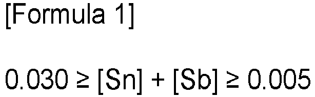
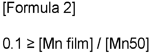
- An exemplary embodiment of the present disclosure provides a non-oriented electrical steel sheet including: a steel sheet base material which includes, by weight: 2.0 to 6.5% of Si, 0.1 to 1.3% of Al, 0.3 to 2.0% of Mn, 0.03% or less (excluding 0%) of Sn, and 0.02% or less (excluding 0%) of Sb, with a balance of Fe and other inevitable impurities and satisfies the following Formula 1, and an insulating coating film positioned on the steel sheet base material, wherein the non-oriented electrical steel sheet satisfies the following Formula 2 before stress relief annealing and satisfies the following Formula 3 after stress relief annealing: 0 .030 ⁇ Sn + Sb ⁇ 0 .005 0 .1 ⁇ Mn coating film / Mn50 10 ⁇ Mn coating film / Mn50 ⁇ 1 wherein [Sn] and [Sb] are contents of Sn and Sb, respectively, [Mn coating film] is an average Mn content (wt%)
- the steel sheet base material may further include 0.005 wt% or less of one or more of C, N, S, Ti, Nb, and V.
- the steel sheet base material may further include one or more of 0.01 to 0.2 wt% of Cu, 0.100 wt% or less of P, 0.002 wt% or less of B, 0.01 wt% or less of Mo, 0.005 wt% or less of Mg, and 0.005 wt% or less of Zr.
- An average crystal grain particle diameter before the stress relief annealing may be 60 ⁇ m or less.
- Iron loss W10/800 (W/kg) after the stress relief annealing may satisfy the following Equation 4: W10/800 ⁇ 25 + 60 ⁇ t wherein t is a thickness (mm) of the steel sheet.
- the stress relief annealing may be performed at a temperature of 800°C to 900°C under an atmosphere which includes one or more of nitrogen, hydrogen, and carbon monoxide and has a dew point of 0°C or lower.
- Another exemplary embodiment of the present disclosure provides a method for manufacturing a non-oriented electrical steel sheet includes: hot rolling a slab which includes, by weight: 2.0 to 6.5% of Si, 0.1 to 1.3% of Al, 0.3 to 2.0% of Mn, 0.03% or less (excluding 0%) of Sn, and 0.02% or less (excluding 0%) of Sb, with a balance of Fe and other inevitable impurities and satisfies the following Formula 1, thereby manufacturing a hot rolled sheet; removing scale present on a surface of the hot rolled sheet; cold rolling the descaled hot rolled sheet to manufacture a cold rolled sheet; and annealing the cold rolled sheet, wherein the removing of scale includes projecting shot balls in an amount of 15 to 35 kg/(min ⁇ m 2 ) onto the steel sheet to remove scale.
- the removing of scale includes projecting shot balls in an amount of 15 to 35 kg/(min ⁇ m 2 ) onto the steel sheet to remove scale.
- the shot balls may have an average particle size of 0.1 to 1 mm, and may be projected for 1 to 60 seconds.
- a material of the shot balls may be a Fe-based alloy.
- the annealing of the cold rolled sheet annealing may be performed at a temperature of 700°C to 1100°C for 10 to 1000 seconds.
- annealing of the hot rolled sheet may be further included.
- stress relief annealing may be further included.
- the stress relief annealing may be performed at a temperature of 800°C to 900°C under an atmosphere which includes one or more of nitrogen, hydrogen, and carbon monoxide and has a dew point of 0°C or lower.
- Still another exemplary embodiment of the present disclosure provides a motor core including: a rotor formed by laminating a plurality of non-oriented electrical steel sheets and a stator formed by laminating a plurality of non-oriented electrical steel sheets,
- the non-oriented electrical steel sheets included in the stator and the rotor may be a non-oriented electrical steel sheet derived from the same coil.
- a difference in contents of Si, Al, and Mn between the non-oriented electrical steel sheets included in the stator and the rotor may be 0.20 wt% or less.
- Sn and Sb are included in a specific range and a shot ball projection amount when removing scale is appropriately adjusted, thereby preventing a Mn component included in a steel sheet base material from diffusing into an insulating coating film during a process of stress relief annealing, so that a binding force between the insulating coating film and the steel sheet base material is maintained.
- performance of motors for environmentally-friendly cars, motors for high-efficiency appliances, and super premium grade motors may be further improved by stress relief annealing.
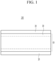
- FIG. 1 is a schematic diagram of a cross-section of a non-oriented electrical steel sheet according to an exemplary embodiment of the present disclosure.
- first, second, and third are used for describing various parts, components, areas, layers, and/or sections, but are not limited thereto. These terms are used only for distinguishing one part, component, area, layer, or section from other parts, components, areas, layers, or sections. Therefore, a first part, component, area, layer, or section described below may be mentioned as a second part, component, area, layer, or section without departing from the scope of the present disclosure.
- % refers to wt%
- 1 ppm refers to 0.0001 wt%
- the meaning of further inclusion of an additional element is replacing iron (Fe) as a balance by the addition amount.
- FIG. 1 schematically shows a cross-section of a non-oriented electrical steel sheet according to an exemplary embodiment of the present disclosure.
- a non-oriented electrical steel sheet 100 includes a steel sheet base material 10 and an insulating coating film 20 positioned on a surface of the steel sheet base material 10.
- the steel sheet base material 10 there may be a surface portion 30 formed from the surface toward the inside of the base material.
- the steel sheet base material 10 includes, by weight: 2.0 to 6.5% of Si, 0.1 to 1.3% of Al, 0.3 to 2.0% of Mn, 0.03% or less (excluding 0%) of Sn, and 0.02% or less (excluding 0%) of Sb, with a balance of Fe and other inevitable impurities.
- Si serves to lower iron loss by increasing the resistivity of a material, and if it is added too little, a high-frequency iron loss improvement effect may be insufficient. On the contrary, if it is added too much, hardness of a material is increased to extremely deteriorate cold rolling properties, so that productivity and blanking properties may become poor. Therefore, Si may be added in the range described above. More specifically, it may be included at 2.0 to 5.0 wt%. More specifically, it may be included at 3.0 to 4.0 wt%.
- Aluminum (Al) serves to lower iron loss by increasing the resistivity of a material. When it is added too little, it is not effective in reducing high-frequency iron loss and a nitride may be finely formed to deteriorate magnetism. On the contrary, when it is added too much, problems are caused in all processes such as steel making and continuous casting, thereby greatly reducing productivity. Therefore, Al may be added in the range described above. More specifically, it may be included at 0.5 to 1.2 wt%. More specifically, it may be included at 0.7 to 1.0 wt%.
- Manganese (Mn) is an element which serves to improve iron loss by increasing the resistivity of a material and form a sulfide. When Mn is added too little, a sulfide may be finely precipitated to deteriorate magnetism. On the contrary, when Mn is added too much, formation of ⁇ 111 ⁇ texture which is unfavorable to magnetism may be promoted so that magnetic flux density may be decreased. Thus, Mn may be added in the range described above. More specifically, Mn may be included at 0.5 to 1.5 wt%.
- resistivity may be 55 to 80 ⁇ •cm.
- Tin (Sn) and antimony (Sb) are added to a crystal grain boundary as segregation elements for suppressing diffusion of nitrogen through the crystal grain boundary, suppressing ⁇ 111 ⁇ texture which is unfavorable to magnetism, and increasing favorable ⁇ 100 ⁇ texture to improve magnetic properties.
- Sn and Sb may be added in the range described above. More specifically, 0.005 to 0.050 wt% of Sn and 0.005 to 0.050 wt% of Sb may be included. More specifically, 0.01 to 0.02 wt% of Sn and 0.01 to 0.02 wt% of Sb may be included.
- Sn and Sb may satisfy the following Formula 1: 0 .030 ⁇ Sn + Sb ⁇ 0 .005 wherein [Sn] and [Sb] are contents (wt%) of Sn and Sb, respectively.
- Sn or Sb is concentrated on the steel sheet surface portion 30, and during stress relief annealing, diffusion of Mn from the steel sheet surface portion 30 to the insulating coating film 20 may be prevented.
- the sum of Sn and Sn is less than 0.005 wt% or less, a large amount of Mn is diffused into the insulating coating film 20, resulting in poor adhesiveness.
- Sn and Sb are included too much also, Mn is strongly prevented from diffusing into the insulating coating film 20, resulting in poor adhesiveness. More specifically, the value of Formula 1 may be 0.010 to 0.025.
- the steel sheet base material 10 may further include one or more of 0.01 to 0.2 wt% of Cu, 0.100 wt% or less of P, 0.002 wt% or less of B, 0.01 wt% of less of Mo, 0.005 wt% or less of Mg, and 0.005 wt% or less of Zr.
- Copper (Cu) serves to form a sulfide with Mn.
- CuMnS may be finely precipitated to deteriorate magnetism. If Cu is added too much, high temperature brittleness may occur to form cracks during soft casting or hot rolling. More specifically, Cu may be further included at 0.05 to 0.10 wt%.
- P phosphorus
- P serves to increase the resistivity of a material and also is segregated in a grain boundary to improve texture to increase the resistivity and lower iron loss, it may be further added.
- P may be added in the range described above. More specifically, P may be included at 0.001 to 0.090 wt%. More specifically, P may be included at 0.005 to 0.085 wt%.
- the steel sheet base material 10 may further include one or more of C, N, S, Ti, Nb, and V at 0.005 wt% or less.
- Carbon (C) when added much, expands an austenite region to increase a phase transformation section, suppresses crystal grain growth of ferrite during annealing to increase iron loss, is bonded to Ti and the like to form a carbide to deteriorate magnetism, and when processed into an electrical product as a final product and then used, increases iron loss by magnetic aging. Therefore, C may be added in the range described above. More specifically, C may be included at 0.003 wt% or less.
- S sulfur
- S forms a fine sulfide inside the base material to suppress crystal grain growth, thereby weakening iron loss
- sulfur it is preferred to add sulfur as little as possible.
- S may be further included at 0.005 wt% or less.
- S may be further included at 0.0030 wt% or less. More specifically, S may be further included at 0.0001 to 0.0030 wt%.
- N Nitrogen (N) is strongly bonded to Al, Ti, and the like to form a nitride and suppress crystal grain growth, and since it hinders movement of a magnetic domain when precipitated, it is preferred to contain less N. Therefore, N may be added in the range described above. More specifically, N may be included at 0.003 wt% or less.
- titanium (Ti), niobium (Nb), vanadium (V) and the like are also strong carbide forming elements, it is preferred not to add them if possible, and they are included at 0.01 wt% or less, respectively.
- the balance includes Fe and inevitable impurities. Since inevitable impurities are impurities incorporated in a manufacturing process of a steel making step and a manufacturing process of the electrical steel sheet and are known in the art, detailed description will be omitted. Addition of elements other than the alloy component described above in an exemplary embodiment of the present disclosure is not excluded, and various elements may be included within a range which does not impair the technical idea of the present disclosure. When an additional element is further included, it replaces Fe as the balance.
- diffusion of Mn into the insulating coating film 20 in stress relief annealing may be suppressed by adding Sn and Sb to the steel sheet base material 10.
- the insulating properties of the insulating coating film may be deteriorated.
- a binding force between the insulating coating film and the base material may be weakened.
- the stress relief annealing may be performed at a temperature of 800°C to 900°C under an atmosphere which includes one or more of nitrogen, hydrogen, and carbon monoxide and has a dew point of 0°C or lower.
- the time may be 10 to 300 minutes.
- the surface portion 30 is formed on the surface of the steel sheet base material 10 on which Sn, Sb, and O are concentrated from the surface of the steel sheet base material 10 toward the inside of the base material. That is, the surface portion 30 is present on an interface between the steel sheet base material 10 and the insulating coating film 20.
- the surface portion 30 serves to hinder diffusion of Mn from the steel sheet base material 10 into the insulating coating film 20.
- the surface portion 30 refers to a portion having an oxygen content of 5 wt% or more, and as oxygen is exposed in the manufacturing process, oxygen in the atmosphere penetrates into the steel sheet and is formed from the surface toward the inside.
- a thickness of the surface portion 30 divided like this may be 10 to 50 nm.
- the surface portion 30 is too thinly formed, it is difficult to appropriately prevent the Mn diffusion described above.
- the surface portion 30 is formed too thick, magnetism may become poor. Therefore, the surface portion 30 may be present at the thickness in the range described above.
- the insulating coating film 20 is positioned on the surface of the steel sheet base material 10.
- the insulating coating film 20 serves to allow insulation between the non-oriented electrical steel sheets, when manufacturing a product by laminating the non-oriented electrical steel sheet.
- the insulating coating film 20 may be treated with an organic, inorganic, and organic and inorganic composite coating film, and may be formed by treatment with a coating agent capable of insulation.
- the insulating coating film 20 when the insulating coating film 20 is formed using a phosphate-based insulating coating film composition, the insulating coating film may include 5 to 50 wt% of P and 0.01 wt% or less of Mn. As such, the insulating coating film 20 before the stress relief annealing includes a small amount of Mn. The balance may be O. 1 to 10 wt% of Si may be further included.
- the insulating coating film 20 before the stress relief annealing may satisfy the following Formula 1: 0.1 ⁇ Mn coating film / Mn50 wherein [Mn coating film] is an average Mn content (wt%) in the insulating coating film, and [Mn50] is a Mn content (wt%) at a depth of 50 ⁇ m from the interface between the steel sheet base material and the insulating coating film toward the inside of the steel sheet base material.
- the insulating coating film after the stress relief annealing may include 2.0 to 25.0 wt% of Mn by partial diffusion of Mn in the steel sheet base material 10. More specifically, it may include 2.0 to 17.0 wt% of Mn. Other components may be the same as those before the stress relief annealing. That is, the insulating coating film 20 after the stress relief annealing may satisfy the following Formula 3: 10 ⁇ Mn coating film / Mn50 ⁇ 1 wherein [Mn coating film] is an average Mn content (wt%) in the insulating coating film.
- the value of Formula 3 may be 2.0 to 9.5. More specifically, the value of Formula 3 may be 3.0 to 9.3.
- the insulating coating film 20 after the stress relief annealing may include 5 to 50 wt% of P and 2.0 to 10.0 wt% of Mn.
- the balance may be O. 1 to 10 wt% of Si may be further included.
- an inorganic material ratio in the insulating coating film is increased to improve stability at a high temperature.
- stability in the stress relief annealing is secured, and a binding force between the base material and the insulating coating film 20 may be maintained even thereafter. Due to the results, after the stress relief annealing, a binding force of 5B or more may be maintained as a result of a crosscut test in accordance with ASTM D3559 which is a binding force test.
- An average crystal grain particle diameter before the stress relief annealing may be 60 ⁇ m or less.
- the average crystal grain particle diameter is small before the stress relief annealing and the mechanical strength of the steel sheet is excellent.
- iron loss W10/800(W/kg) after the stress relief annealing may satisfy the following Formula 4: W10 / 800 ⁇ 25 + 60 ⁇ t wherein t is a thickness (mm) of the steel sheet.
- stress relief annealing is performed.
- W10/800 ⁇ 21 + 60 ⁇ t may be satisfied.
- a method for manufacturing a non-oriented electrical steel sheet includes: hot rolling a slab to manufacture a hot rolled sheet; cold rolling the hot rolled sheet to manufacture a cold rolled sheet; and annealing the cold rolled sheet.
- a slab is hot rolled.
- the alloy components of the slab are as described in the alloy components of the non-oriented electrical steel sheet, redundant description will be omitted. Since the alloy components are not substantially changed in the manufacturing process of the non-oriented electrical steel sheet, the alloy components of the non-oriented electrical steel sheet and those of the slab are substantially the same.
- the slab includes, by weight: 2.0 to 6.5% of Si, 0.1 to 1.3% of Al, 0.3 to 2.0% of Mn, 0.03% or less (excluding 0%) of Sn, and 0.02% or less (excluding 0%) of Sb, with a balance of Fe and other inevitable impurities.
- the slab satisfies the following Formula 1: 0.030 ⁇ Sn + Sb ⁇ 0.005 wherein [Sn] and [Sb] are contents (wt%) of Sn and Sb, respectively.
- the slab may be heated before hot rolling. Though the heating temperature of the slab is not limited, the slab may be heated to 1100 to 1250°C. When the slab heating temperature is too high, precipitates which harm magnetism may be dissolved again and finely precipitated after the hot rolling.
- the hot rolled sheet may have a thickness of 2 to 3.0 mm.
- annealing of the hot rolled sheet may be further included. It is preferred to perform the hot rolled sheet annealing in manufacturing a high grade electrical steel sheet having no phase transformation, and the hot rolled sheet annealing is effective for improving magnetic flux density by improving the texture of a final annealed sheet.
- the annealing of the hot rolled sheet may be performed at a temperature of 850 to 1200°C.
- the hot rolled sheet annealing temperature is too low, the texture does not grow or finely grows, so that it is difficult to expect an effect of increasing magnetic flux density.
- the hot rolled sheet annealing temperature is too high, the magnetic properties are rather deteriorated, and rolling workability may become poor due to the deformation of a plate shape.
- the hot rolled sheet annealing is performed for increasing orientation favorable to magnetism, if necessary, and may be omitted.
- a shot ball projection amount is increased to contribute to formation of a Sn/Sb concentrated layer on the surface of the base material, which adjusts Mn diffusion into the insulating coating film.
- the removing of scale includes removing scale by projecting shot balls in an amount of 15 to 35 kg/(min ⁇ m 2 ) onto the steel sheet.
- the shot ball projection amount is too small, a residual oxide layer on the surface hinders formation of the Sn/Sb concentrated layer, so that it is difficult to adjust Mn diffusion.
- the shot ball projection amount is too large, the surface of the steel sheet is much damaged, and thus, the upper limit may be appropriately adjusted. More specifically, the shot balls may be projected in an amount of 17 to 30 kg/(min ⁇ m 2 ) onto the steel sheet.
- the shot balls may have an average particle size of 0.1 to 1 mm and may be projected for 1 to 60 seconds. More specifically, the shot balls may have an average particle size of 0.3 to 0.8 mm and may be projected for 5 to 30 seconds.
- the average particle size and the projection time of the shot balls also affect diffusion of Mn into the insulating coating film.
- the material of the shot balls is not limited, a Fe-based alloy may be used.
- the hot rolled sheet is cold rolled to manufacture a cold rolled sheet.
- the cold rolling is final rolling to a thickness of 0.15 mm to 0.65 mm.
- second cold rolling may be performed after the first cold rolling and intermediate annealing, and a final reduction rate may be in a range of 50 to 95%.
- the cold rolled sheet is annealed.
- Cold rolled sheet annealing is performed in a range of 700 to 1100°C for 10 to 1000 seconds so that the crystal grain size on the steel sheet cross-section is 20 to 150 ⁇ m.
- the cold rolled sheet annealing temperature is too low, crystal grains are small, so that iron loss may be deteriorated.
- the temperature is too high, crystal grains are coarsened and abnormal vortex loss is increased to increase total iron loss. More specifically, the annealing may be performed in a range of 900 to 1050°C.
- a heating rate to cracks may be 30 to 150°C/sec.
- the heating rate is appropriately adjusted, an oxide layer is thinly and densely formed, so that Mn diffusion may be prevented.
- the annealing of the cold rolled sheet may be performed under an atmosphere which includes 40 vol% or less of hydrogen (H 2 ) and 60 vol% or more of nitrogen and has a dew point of 0 to -40°C. Specifically, the annealing may be performed under an atmosphere including 0 to 10 vol% of hydrogen and 90 to 100 vol% of nitrogen. When the annealing atmosphere is appropriately adjusted, the oxide layer is thinly and densely formed, so that Mn diffusion may be prevented.
- the insulating coating film may be formed after the cold rolled sheet annealing.
- the insulating coating film may be treated with organic, inorganic, and organic and inorganic composite coating films, and may also be treated with other coating agent capable of insulation.
- it may be formed by applying an insulating coating film forming composition including 40 to 70 wt% of a metal phosphate and 0.5 to 10 wt% of silica.
- the insulating coating film include 5 wt% or more of P, and the steel sheet base material includes less than 5 wt% of P, so that they are divided.
- stress relief annealing is performed.
- the stress relief annealing is performed at a temperature of 700°C to 850°C for 10 to 300 minutes.
- a motor core includes a rotor formed by laminating a plurality of non-oriented electrical steel sheets and a stator formed by laminating a plurality of non-oriented electrical steel sheets.
- the non-oriented electrical steel sheet in the rotor includes, by weight: 2.0 to 6.5% of Si, 0.1 to 1.3% of Al, 0.3 to 2.0% of Mn, 0.03% or less (excluding 0%) of Sn, and 0.02% or less (excluding 0%) of Sb, with a balance of Fe and other inevitable impurities, and satisfies the following Formulae 1 and 2.
- the non-oriented electrical steel sheet in the stator includes, by weight: 2.0 to 6.5% of Si, 0.1 to 1.3% of Al, 0.3 to 2.0% of Mn, 0.03% or less (excluding 0%) of Sn, and 0.02% or less (excluding 0%) of Sb, with a balance of Fe and other inevitable impurities, and satisfies the following Formulae 1 and 3.
- [Sn] and [Sb] are contents of Sn and Sb, respectively
- [Mn coating film] is an average Mn content (wt%) in the insulating coating film
- [Mn50] is a Mn content (wt%) at a depth of 50 ⁇ m from an interface between the steel sheet base material and the insulating coating film toward the inside of the steel sheet base material.
- the mechanical properties is more important than the magnetic properties. Therefore, an SPA process which may deteriorate mechanical properties may be omitted.
- the characteristics of the non-oriented electrical steel sheet before SRA are derived. Steel components, Mn diffusion, and Mn in the insulating coating film are described in relation to the non-oriented electrical steel sheet described above, redundant description will be omitted.
- the magnetic properties are more important than the mechanical properties, and improvement of magnetism may be promoted by SRA after blanking and lamination. Therefore, the characteristics of the non-oriented electrical steel sheet are shown in the stator after SRA. Since the steel components of the non-oriented electrical steel sheet, the Mn diffusion, and Mn in the insulating coating film are described in relation to the non-oriented electrical steel sheet described above, redundant description will be omitted.
- stator and the rotor are roughly blanked into a donut or disk shape.
- the stator and the rotor are manufactured by blanking from a separate coil of the non-oriented electrical steel sheet, respectively, the blanked remaining part are scrap treated, which leads to rising process costs and waste of resources and energy.
- the scrap treated part may be minimized.
- the non-oriented electrical steel sheet included in the stator and the rotor in an exemplary embodiment of the present disclosure may be a non-oriented electrical steel sheet derived from the same coil.
- the meaning of being derived from the same coil in an exemplary embodiment of the present disclosure is that steel components such as Si, Al, and Mn in the non-oriented electrical steel sheet included in the stator and the rotor are substantially the same. Specifically, it means that a difference in Si, Al, and Mn contents between the stator and the rotor is 0.20 wt% or less, respectively. More specifically, it means that a difference in Si, Al, and Mn contents between the stator and the rotor is 0.10 wt% or less, respectively.
- a difference in Si, Al, and Mn contents between the stator and the rotor is 0.05 wt% or less, respectively. More specifically, it means that a difference in Si, Al, and Mn contents between the stator and the rotor is 0.01 wt% or less, respectively. In the case of Sn and Sb, a content difference may be 0.01 wt% or less, respectively. More specifically, it may be 0.005 wt% or less. More specifically, it may be 0.001 wt% or less.
- the components of the insulating coating films of the stator and the rotor may also be substantially the same.
- Slabs including the components of the following Table 1 and Table 2 with a balance of Fe and other inevitable impurities were manufactured.
- the slabs were heated to 1150°C and hot finish rolled at 850°C to manufacture hot rolled sheets having a sheet thickness of 2.3 mm.
- the hot rolled sheets were annealed at 1100°C for 4 minutes, and then blasted in the shot ball projection amount summarized in the following Table 3 to remove scale. Thereafter, cold rolling was performed to set the sheet thickness to 0.27 mm, heating was performed at 100°C/sec, and final annealing was performed at 970°C for 5 minutes under a nitrogen atmosphere.
- the insulating coating film was formed at a thickness of 0.5 ⁇ m using an insulating coating film composition including 50 wt% of an Al phosphate and 5 wt% of silica.
- Adhesiveness was measured by a Crosscut Test (ASTM D3359) method.
- Table 1 (wt%) Si Al Mn Sn Sb Sn+Sb 1 2.0 1.1 0.6 0.01 0.005 0.015 2 2.8 0.9 0.9 0.01 0.004 0.014 3 3.1 0.7 1.2 0.012 0.016 0.028 4 3.3 0.7 1.2 0.012 0.016 0.028 5 4.0 0.3 1.8 0.012 0.014 0.026 6 4.7 0.1 2 0.025 0.003 0.028 7 5.4 1.2 1.7 0.005 0.02 0.025 8 6.0 0.8 1.1 0.005 0.013 0.018 9 1.8 1.3 0.3 0.01 0.006 0.016 10 7.0 0.4 0.5 0.01 0.01 0.02 11 3.1 0.08 1.5 0.02 0.05 0.07 12 3.9 1.5 1.8 0.02 0.04 0.06 13 3.2 0.6 0.2 0.02 0.04 0.06 14 3.8 0.9 2.3 0.02 0.06 0.08 15 3.3 0.7 1.3 - 0.
Landscapes
- Chemical & Material Sciences (AREA)
- Engineering & Computer Science (AREA)
- Materials Engineering (AREA)
- Mechanical Engineering (AREA)
- Metallurgy (AREA)
- Organic Chemistry (AREA)
- Physics & Mathematics (AREA)
- Crystallography & Structural Chemistry (AREA)
- Thermal Sciences (AREA)
- Electromagnetism (AREA)
- Manufacturing & Machinery (AREA)
- Power Engineering (AREA)
- General Chemical & Material Sciences (AREA)
- Chemical Kinetics & Catalysis (AREA)
- Dispersion Chemistry (AREA)
- Health & Medical Sciences (AREA)
- Child & Adolescent Psychology (AREA)
- Soft Magnetic Materials (AREA)
- Manufacturing Of Steel Electrode Plates (AREA)
- Iron Core Of Rotating Electric Machines (AREA)
Abstract

Description
- An embodiment of the present disclosure relates to a non-oriented electrical steel sheet and a motor core including the same. Specifically, an embodiment of the present disclosure relates to a non-oriented electrical steel sheet which has improved adhesiveness of an insulating coating film by appropriately adjusting contents of Sn and Sb and increasing a shot ball projection amount when removing scale to prevent Mn diffusion into an insulating coating film during stress relief annealing, and a motor core including the same.
- A non-oriented electrical steel sheet is mainly used in a motor which converts electrical energy into mechanical energy, and in order to exhibit high efficiency in this process, the non-oriented electrical steel sheet is required to have excellent magnetic properties. In particular, in recent years, as environmentally-friendly technology has been gaining attention, it is considered to be very important to increase the efficiency of motors, which accounts for more than a half of total electrical energy consumption, and to this end, the demand for a non-oriented electrical steel sheet having excellent magnetic properties is also increasing.
- The magnetic properties of the non-oriented electrical steel sheet is mainly evaluated by iron loss and magnetic flux density.
- Iron loss refers to energy loss occurring at certain magnetic flux density and frequency, and magnetic flux density refers to a magnetization degree obtained under the certain magnetic field. As the iron loss is lower, a motor having higher energy efficiency may be manufactured under the same conditions, and as the magnetic flux density is higher, the motor may be miniaturized or copper loss may be decreased. Thus, it is important to manufacture a non-oriented electrical steel sheet having low iron loss and high magnetic flux density.
- The characteristics of the non-oriented electrical steel sheet to be considered also vary depending on the operation conditions of the motor. As a criterion for evaluating the characteristics of the non-oriented electrical steel sheet to be used in the motor, W15/50 which is iron loss when a 1.5 T magnetic field is applied to a plurality of motors at a commercial frequency of 50 Hz is considered to be the most important. However, the W15/50 iron loss is not considered to be the most important in all motors of various uses, and iron loss at another frequency or applied magnetic field is also evaluated depending on main operation conditions. In particular, in the non-oriented electrical steel sheet used in a drive motor of the recent electric vehicles, since magnetic properties are often important at a low magnetic field of 1.0 T or less and a high frequency of 400 Hz or more, the characteristics of the non-oriented electrical steel sheet are evaluated by iron loss such as W10/400.
- In order to manufacture products such as a motor or a transformer from the non-oriented electrical steel sheet, the non-oriented electrical steel sheet should be slit into a specific shape. In this process, stress is imparted to the non-oriented electrical steel sheet, and in order to remove the stress, stress relief annealing is performed.
- In the stress relief annealing process, a Mn component in the steel sheet diffuses into an insulating coating film, which becomes the cause of decreased adhesiveness between the steel sheet and the insulating coating film. Though there was an attempt to suppress diffusion of Mn by adding Sb and Sn and adjusting a content relationship between Al and Mn, the attempt had limitations. Suppression of diffusion of Mn through formation of a surface oxide layer and a surface segregation element layer had little effect, which results in weakening of a binding force between an insulating coating and a base material.
- The present disclosure attempts to provide a non-oriented electrical steel sheet and a motor core including the same. Specifically, the present disclosure attempts to provide a non-oriented electrical steel sheet having improved adhesiveness of an insulating coating film, by appropriately adjusting contents of Sn and Sb and appropriately adjusting a shot ball projection amount when removing scale of a hot rolled sheet to prevent Mn diffusion into the insulating coating film during stress relief annealing, and a motor core including the same.
- An exemplary embodiment of the present disclosure provides a non-oriented electrical steel sheet including: a steel sheet base material which includes, by weight: 2.0 to 6.5% of Si, 0.1 to 1.3% of Al, 0.3 to 2.0% of Mn, 0.03% or less (excluding 0%) of Sn, and 0.02% or less (excluding 0%) of Sb, with a balance of Fe and other inevitable impurities and satisfies the following Formula 1, and an insulating coating film positioned on the steel sheet base material, wherein the non-oriented electrical steel sheet satisfies the following Formula 2 before stress relief annealing and satisfies the following Formula 3 after stress relief annealing:


- The steel sheet base material may further include 0.005 wt% or less of one or more of C, N, S, Ti, Nb, and V.
- The steel sheet base material may further include one or more of 0.01 to 0.2 wt% of Cu, 0.100 wt% or less of P, 0.002 wt% or less of B, 0.01 wt% or less of Mo, 0.005 wt% or less of Mg, and 0.005 wt% or less of Zr.
- An average crystal grain particle diameter before the stress relief annealing may be 60 µm or less.
- Iron loss W10/800 (W/kg) after the stress relief annealing may satisfy the following Equation 4:

- The stress relief annealing may be performed at a temperature of 800°C to 900°C under an atmosphere which includes one or more of nitrogen, hydrogen, and carbon monoxide and has a dew point of 0°C or lower.
- Another exemplary embodiment of the present disclosure provides a method for manufacturing a non-oriented electrical steel sheet includes: hot rolling a slab which includes, by weight: 2.0 to 6.5% of Si, 0.1 to 1.3% of Al, 0.3 to 2.0% of Mn, 0.03% or less (excluding 0%) of Sn, and 0.02% or less (excluding 0%) of Sb, with a balance of Fe and other inevitable impurities and satisfies the following Formula 1, thereby manufacturing a hot rolled sheet; removing scale present on a surface of the hot rolled sheet; cold rolling the descaled hot rolled sheet to manufacture a cold rolled sheet; and annealing the cold rolled sheet, wherein the removing of scale includes projecting shot balls in an amount of 15 to 35 kg/(min·m2) onto the steel sheet to remove scale.

- The shot balls may have an average particle size of 0.1 to 1 mm, and may be projected for 1 to 60 seconds.
- A material of the shot balls may be a Fe-based alloy.
- The annealing of the cold rolled sheet annealing may be performed at a temperature of 700°C to 1100°C for 10 to 1000 seconds.
- Before the removing of scale, annealing of the hot rolled sheet may be further included.
- After the annealing of the cold rolled sheet, stress relief annealing may be further included.
- The stress relief annealing may be performed at a temperature of 800°C to 900°C under an atmosphere which includes one or more of nitrogen, hydrogen, and carbon monoxide and has a dew point of 0°C or lower.
- Still another exemplary embodiment of the present disclosure provides a motor core including: a rotor formed by laminating a plurality of non-oriented electrical steel sheets and a stator formed by laminating a plurality of non-oriented electrical steel sheets,
- wherein the non-oriented electrical steel sheet in the rotor includes, by weight: 2.0 to 6.5% of Si, 0.1 to 1.3% of Al, 0.3 to 2.0% of Mn, 0.03% or less (excluding 0%) of Sn, and 0.02% or less (excluding 0%) of Sb, with a balance of Fe and other inevitable impurities, and satisfies the following Formulae 1 and 2, and
- the non-oriented electrical steel sheet in the stator includes, by weight: 2.0 to 6.5% of Si, 0.1 to 1.3% of Al, 0.3 to 2.0% of Mn, 0.03% or less (excluding 0%) of Sn, and 0.02% or less (excluding 0%) of Sb, with a balance of Fe and other inevitable impurities, and satisfies the following Formulae 1 to 3:


- The non-oriented electrical steel sheets included in the stator and the rotor may be a non-oriented electrical steel sheet derived from the same coil.
- A difference in contents of Si, Al, and Mn between the non-oriented electrical steel sheets included in the stator and the rotor may be 0.20 wt% or less.
- According to an exemplary embodiment, Sn and Sb are included in a specific range and a shot ball projection amount when removing scale is appropriately adjusted, thereby preventing a Mn component included in a steel sheet base material from diffusing into an insulating coating film during a process of stress relief annealing, so that a binding force between the insulating coating film and the steel sheet base material is maintained.
- Thus, performance of motors for environmentally-friendly cars, motors for high-efficiency appliances, and super premium grade motors may be further improved by stress relief annealing.
-
FIG. 1 is a schematic diagram of a cross-section of a non-oriented electrical steel sheet according to an exemplary embodiment of the present disclosure. - The terms such as first, second, and third are used for describing various parts, components, areas, layers, and/or sections, but are not limited thereto. These terms are used only for distinguishing one part, component, area, layer, or section from other parts, components, areas, layers, or sections. Therefore, a first part, component, area, layer, or section described below may be mentioned as a second part, component, area, layer, or section without departing from the scope of the present disclosure.
- The terminology used herein is only for mentioning a certain example, and is not intended to limit the present disclosure. Singular forms used herein also include plural forms unless otherwise stated clearly to the contrary. The meaning of "comprising" used in the specification is embodying certain characteristics, areas, integers, steps, operations, elements, and/or components, but is not excluding the presence or addition of other characteristics, areas, integers, steps, operations, elements, and/or components.
- In the present specification, when it is mentioned that a part is "on" or "above" the other part, it means that the part is directly on or above the other part or another part may be interposed therebetween. In contrast, when it is mentioned that a part is "directly on" the other part, it means that nothing is interposed therebetween.
- In addition, unless otherwise particularly described, % refers to wt%, and 1 ppm refers to 0.0001 wt%.
- In an exemplary embodiment of the present disclosure, the meaning of further inclusion of an additional element is replacing iron (Fe) as a balance by the addition amount.
- Though not defined otherwise, all terms including technical terms and scientific terms used herein have the same meaning as commonly understood by a person with ordinary skill in the art to which the present disclosure pertains. Terms defined in commonly used dictionaries are further interpreted as having a meaning consistent with the related technical literatures and the currently disclosed description, and unless otherwise defined, they are not interpreted as having an ideal or very formal meaning.
- Hereinafter, an exemplary embodiment of the present disclosure will be described in detail so that a person with ordinary skill in the art to which the present disclosure pertains may easily carry out the present disclosure. As those skilled in the art would realize, the described embodiments may be modified in various different ways, all without departing from the spirit or scope of the present disclosure.
-
FIG. 1 schematically shows a cross-section of a non-oriented electrical steel sheet according to an exemplary embodiment of the present disclosure. As shown inFIG. 1 , a non-orientedelectrical steel sheet 100 includes a steelsheet base material 10 and aninsulating coating film 20 positioned on a surface of the steelsheet base material 10. In the steelsheet base material 10, there may be asurface portion 30 formed from the surface toward the inside of the base material. - The steel
sheet base material 10 according to an exemplary embodiment of the present disclosure includes, by weight: 2.0 to 6.5% of Si, 0.1 to 1.3% of Al, 0.3 to 2.0% of Mn, 0.03% or less (excluding 0%) of Sn, and 0.02% or less (excluding 0%) of Sb, with a balance of Fe and other inevitable impurities. - Hereinafter, the reasons for limiting components of the steel
sheet base material 10 will be described first. - Silicon (Si) serves to lower iron loss by increasing the resistivity of a material, and if it is added too little, a high-frequency iron loss improvement effect may be insufficient. On the contrary, if it is added too much, hardness of a material is increased to extremely deteriorate cold rolling properties, so that productivity and blanking properties may become poor. Therefore, Si may be added in the range described above. More specifically, it may be included at 2.0 to 5.0 wt%. More specifically, it may be included at 3.0 to 4.0 wt%.
- Aluminum (Al) serves to lower iron loss by increasing the resistivity of a material. When it is added too little, it is not effective in reducing high-frequency iron loss and a nitride may be finely formed to deteriorate magnetism. On the contrary, when it is added too much, problems are caused in all processes such as steel making and continuous casting, thereby greatly reducing productivity. Therefore, Al may be added in the range described above. More specifically, it may be included at 0.5 to 1.2 wt%. More specifically, it may be included at 0.7 to 1.0 wt%.
- Manganese (Mn) is an element which serves to improve iron loss by increasing the resistivity of a material and form a sulfide. When Mn is added too little, a sulfide may be finely precipitated to deteriorate magnetism. On the contrary, when Mn is added too much, formation of {111} texture which is unfavorable to magnetism may be promoted so that magnetic flux density may be decreased. Thus, Mn may be added in the range described above. More specifically, Mn may be included at 0.5 to 1.5 wt%.
- In an exemplary embodiment of the present disclosure, resistivity may be 55 to 80 µΩ•cm.
- Tin (Sn) and antimony (Sb) are added to a crystal grain boundary as segregation elements for suppressing diffusion of nitrogen through the crystal grain boundary, suppressing {111} texture which is unfavorable to magnetism, and increasing favorable {100} texture to improve magnetic properties. When Sn and Sb are added too much, respectively, crystal grain growth is hindered to deteriorate magnetism and rolling properties. Therefore, Sn and Sb may be added in the range described above. More specifically, 0.005 to 0.050 wt% of Sn and 0.005 to 0.050 wt% of Sb may be included. More specifically, 0.01 to 0.02 wt% of Sn and 0.01 to 0.02 wt% of Sb may be included.
- Sn and Sb may satisfy the following Formula 1:

- In an exemplary embodiment of the present disclosure, Sn or Sb is concentrated on the steel
sheet surface portion 30, and during stress relief annealing, diffusion of Mn from the steelsheet surface portion 30 to the insulatingcoating film 20 may be prevented. When the sum of Sn and Sn is less than 0.005 wt% or less, a large amount of Mn is diffused into the insulatingcoating film 20, resulting in poor adhesiveness. On the contrary, when Sn and Sb are included too much also, Mn is strongly prevented from diffusing into the insulatingcoating film 20, resulting in poor adhesiveness. More specifically, the value of Formula 1 may be 0.010 to 0.025. - The steel
sheet base material 10 may further include one or more of 0.01 to 0.2 wt% of Cu, 0.100 wt% or less of P, 0.002 wt% or less of B, 0.01 wt% of less of Mo, 0.005 wt% or less of Mg, and 0.005 wt% or less of Zr. - Copper (Cu) serves to form a sulfide with Mn. When Cu is further added, if it is added too little, CuMnS may be finely precipitated to deteriorate magnetism. If Cu is added too much, high temperature brittleness may occur to form cracks during soft casting or hot rolling. More specifically, Cu may be further included at 0.05 to 0.10 wt%.
- Since phosphorus (P) serves to increase the resistivity of a material and also is segregated in a grain boundary to improve texture to increase the resistivity and lower iron loss, it may be further added. However, when the amount of P added is too much, formation of texture which is unfavorable to magnetism is caused so that there is no effect of texture improvement, and P is excessively segregated in the grain boundary to deteriorate rollability and workability, which makes production difficult. Therefore, P may be added in the range described above. More specifically, P may be included at 0.001 to 0.090 wt%. More specifically, P may be included at 0.005 to 0.085 wt%.
- Since boron (B), molybdenum (Mo), magnesium (Mg), and zirconium (Zr) react with impurity elements to form fine sulfides, carbides, and nitrides and have an adverse effect on magnetism, their contents may be limited as described above.
- The steel
sheet base material 10 may further include one or more of C, N, S, Ti, Nb, and V at 0.005 wt% or less. - Carbon (C), when added much, expands an austenite region to increase a phase transformation section, suppresses crystal grain growth of ferrite during annealing to increase iron loss, is bonded to Ti and the like to form a carbide to deteriorate magnetism, and when processed into an electrical product as a final product and then used, increases iron loss by magnetic aging. Therefore, C may be added in the range described above. More specifically, C may be included at 0.003 wt% or less.
- Since sulfur (S) forms a fine sulfide inside the base material to suppress crystal grain growth, thereby weakening iron loss, it is preferred to add sulfur as little as possible. When S is included in a large amount, it is bonded to Mn and the like to form a precipitate or cause high temperature brittleness during hot rolling. Therefore, S may be further included at 0.005 wt% or less. Specifically, S may be further included at 0.0030 wt% or less. More specifically, S may be further included at 0.0001 to 0.0030 wt%.
- Nitrogen (N) is strongly bonded to Al, Ti, and the like to form a nitride and suppress crystal grain growth, and since it hinders movement of a magnetic domain when precipitated, it is preferred to contain less N. Therefore, N may be added in the range described above. More specifically, N may be included at 0.003 wt% or less.
- Since titanium (Ti), niobium (Nb), vanadium (V) and the like are also strong carbide forming elements, it is preferred not to add them if possible, and they are included at 0.01 wt% or less, respectively.
- The balance includes Fe and inevitable impurities. Since inevitable impurities are impurities incorporated in a manufacturing process of a steel making step and a manufacturing process of the electrical steel sheet and are known in the art, detailed description will be omitted. Addition of elements other than the alloy component described above in an exemplary embodiment of the present disclosure is not excluded, and various elements may be included within a range which does not impair the technical idea of the present disclosure. When an additional element is further included, it replaces Fe as the balance.
- In an exemplary embodiment of the present disclosure, diffusion of Mn into the insulating
coating film 20 in stress relief annealing may be suppressed by adding Sn and Sb to the steelsheet base material 10. - When the Mn component is increased too much by much Mn diffusion into the insulating
coating film 20, the insulating properties of the insulating coating film may be deteriorated. In addition, a binding force between the insulating coating film and the base material may be weakened. - When a Mn concentration at a depth of 50 µm from the surface of the steel
sheet base material 10 toward the inside of the base material is [Mn50] and the Mn concentration of the insulatingcoating film 20 is [Mn coating film], the following Formula 3 is satisfied before the stress relief annealing and the following Formula 3 is satisfied after the stress relief annealing.

- The stress relief annealing may be performed at a temperature of 800°C to 900°C under an atmosphere which includes one or more of nitrogen, hydrogen, and carbon monoxide and has a dew point of 0°C or lower. The time may be 10 to 300 minutes.
- By adding Sn and Sb to the steel
sheet base material 10, thesurface portion 30 is formed on the surface of the steelsheet base material 10 on which Sn, Sb, and O are concentrated from the surface of the steelsheet base material 10 toward the inside of the base material. That is, thesurface portion 30 is present on an interface between the steelsheet base material 10 and the insulatingcoating film 20. Thesurface portion 30 serves to hinder diffusion of Mn from the steelsheet base material 10 into the insulatingcoating film 20. Thesurface portion 30 refers to a portion having an oxygen content of 5 wt% or more, and as oxygen is exposed in the manufacturing process, oxygen in the atmosphere penetrates into the steel sheet and is formed from the surface toward the inside. - A thickness of the
surface portion 30 divided like this may be 10 to 50 nm. When thesurface portion 30 is too thinly formed, it is difficult to appropriately prevent the Mn diffusion described above. When thesurface portion 30 is formed too thick, magnetism may become poor. Therefore, thesurface portion 30 may be present at the thickness in the range described above. - The insulating
coating film 20 is positioned on the surface of the steelsheet base material 10. The insulatingcoating film 20 serves to allow insulation between the non-oriented electrical steel sheets, when manufacturing a product by laminating the non-oriented electrical steel sheet. The insulatingcoating film 20 may be treated with an organic, inorganic, and organic and inorganic composite coating film, and may be formed by treatment with a coating agent capable of insulation. - For example, when the insulating
coating film 20 is formed using a phosphate-based insulating coating film composition, the insulating coating film may include 5 to 50 wt% of P and 0.01 wt% or less of Mn. As such, the insulatingcoating film 20 before the stress relief annealing includes a small amount of Mn. The balance may be O. 1 to 10 wt% of Si may be further included. - The insulating
coating film 20 before the stress relief annealing may satisfy the following Formula 1: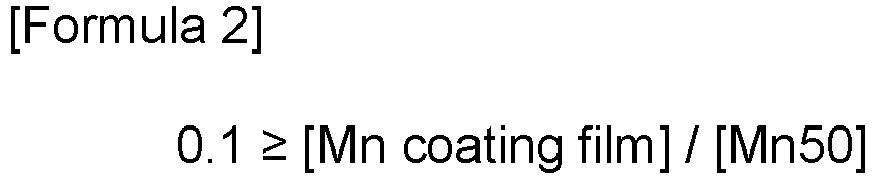
- Meanwhile, the insulating coating film after the stress relief annealing may include 2.0 to 25.0 wt% of Mn by partial diffusion of Mn in the steel
sheet base material 10. More specifically, it may include 2.0 to 17.0 wt% of Mn. Other components may be the same as those before the stress relief annealing. That is, the insulatingcoating film 20 after the stress relief annealing may satisfy the following Formula 3:
- More specifically, the value of Formula 3 may be 2.0 to 9.5. More specifically, the value of Formula 3 may be 3.0 to 9.3.
- That is, the insulating
coating film 20 after the stress relief annealing may include 5 to 50 wt% of P and 2.0 to 10.0 wt% of Mn. The balance may be O. 1 to 10 wt% of Si may be further included. - When an appropriate amount of Mn diffusion into the insulating
coating film 20 proceeds, an inorganic material ratio in the insulating coating film is increased to improve stability at a high temperature. In this case, stability in the stress relief annealing is secured, and a binding force between the base material and the insulatingcoating film 20 may be maintained even thereafter. Due to the results, after the stress relief annealing, a binding force of 5B or more may be maintained as a result of a crosscut test in accordance with ASTM D3559 which is a binding force test. - An average crystal grain particle diameter before the stress relief annealing may be 60 µm or less. The average crystal grain particle diameter is small before the stress relief annealing and the mechanical strength of the steel sheet is excellent.
- Meanwhile, iron loss W10/800(W/kg) after the stress relief annealing may satisfy the following Formula 4:

- In order to improve iron loss after the stress relief annealing, stress relief annealing is performed.
- More specifically, W10/800 ≤ 21 + 60 × t may be satisfied.
- A method for manufacturing a non-oriented electrical steel sheet includes: hot rolling a slab to manufacture a hot rolled sheet; cold rolling the hot rolled sheet to manufacture a cold rolled sheet; and annealing the cold rolled sheet.
- First, a slab is hot rolled.
- Since the alloy components of the slab are as described in the alloy components of the non-oriented electrical steel sheet, redundant description will be omitted. Since the alloy components are not substantially changed in the manufacturing process of the non-oriented electrical steel sheet, the alloy components of the non-oriented electrical steel sheet and those of the slab are substantially the same.
- Specifically, the slab includes, by weight: 2.0 to 6.5% of Si, 0.1 to 1.3% of Al, 0.3 to 2.0% of Mn, 0.03% or less (excluding 0%) of Sn, and 0.02% or less (excluding 0%) of Sb, with a balance of Fe and other inevitable impurities. The slab satisfies the following Formula 1:

- Since other additional elements are described in the alloy components of the non-oriented electrical steel sheet, redundant description will be omitted.
- The slab may be heated before hot rolling. Though the heating temperature of the slab is not limited, the slab may be heated to 1100 to 1250°C. When the slab heating temperature is too high, precipitates which harm magnetism may be dissolved again and finely precipitated after the hot rolling.
- Next, the slab is hot rolled to manufacture a hot rolled sheet. The hot rolled sheet may have a thickness of 2 to 3.0 mm.
- After the manufacturing of the hot rolled sheet, annealing of the hot rolled sheet may be further included. It is preferred to perform the hot rolled sheet annealing in manufacturing a high grade electrical steel sheet having no phase transformation, and the hot rolled sheet annealing is effective for improving magnetic flux density by improving the texture of a final annealed sheet.
- Herein, the annealing of the hot rolled sheet may be performed at a temperature of 850 to 1200°C. When the hot rolled sheet annealing temperature is too low, the texture does not grow or finely grows, so that it is difficult to expect an effect of increasing magnetic flux density. When the hot rolled sheet annealing temperature is too high, the magnetic properties are rather deteriorated, and rolling workability may become poor due to the deformation of a plate shape. The hot rolled sheet annealing is performed for increasing orientation favorable to magnetism, if necessary, and may be omitted.
- Next, scale present on the surface of the hot rolled sheet or the annealed hot rolled sheet is removed. In an exemplary embodiment of the present disclosure, a shot ball projection amount is increased to contribute to formation of a Sn/Sb concentrated layer on the surface of the base material, which adjusts Mn diffusion into the insulating coating film.
- The removing of scale includes removing scale by projecting shot balls in an amount of 15 to 35 kg/(min·m2) onto the steel sheet. When the shot ball projection amount is too small, a residual oxide layer on the surface hinders formation of the Sn/Sb concentrated layer, so that it is difficult to adjust Mn diffusion. On the contrary, when the shot ball projection amount is too large, the surface of the steel sheet is much damaged, and thus, the upper limit may be appropriately adjusted. More specifically, the shot balls may be projected in an amount of 17 to 30 kg/(min·m2) onto the steel sheet.
- The shot balls may have an average particle size of 0.1 to 1 mm and may be projected for 1 to 60 seconds. More specifically, the shot balls may have an average particle size of 0.3 to 0.8 mm and may be projected for 5 to 30 seconds. The average particle size and the projection time of the shot balls also affect diffusion of Mn into the insulating coating film.
- Though the material of the shot balls is not limited, a Fe-based alloy may be used.
- Next, the hot rolled sheet is cold rolled to manufacture a cold rolled sheet. The cold rolling is final rolling to a thickness of 0.15 mm to 0.65 mm. If necessary, second cold rolling may be performed after the first cold rolling and intermediate annealing, and a final reduction rate may be in a range of 50 to 95%.
- Next, the cold rolled sheet is annealed. Cold rolled sheet annealing is performed in a range of 700 to 1100°C for 10 to 1000 seconds so that the crystal grain size on the steel sheet cross-section is 20 to 150 µm. When the cold rolled sheet annealing temperature is too low, crystal grains are small, so that iron loss may be deteriorated. When the temperature is too high, crystal grains are coarsened and abnormal vortex loss is increased to increase total iron loss. More specifically, the annealing may be performed in a range of 900 to 1050°C.
- After the cold rolled sheet annealing, all (99% or more) of the texture worked by the cold rolling of the steel sheet may be recrystallized.
- During the cold rolled sheet annealing, a heating rate to cracks may be 30 to 150°C/sec. When the heating rate is appropriately adjusted, an oxide layer is thinly and densely formed, so that Mn diffusion may be prevented.
- The annealing of the cold rolled sheet may be performed under an atmosphere which includes 40 vol% or less of hydrogen (H2) and 60 vol% or more of nitrogen and has a dew point of 0 to -40°C. Specifically, the annealing may be performed under an atmosphere including 0 to 10 vol% of hydrogen and 90 to 100 vol% of nitrogen. When the annealing atmosphere is appropriately adjusted, the oxide layer is thinly and densely formed, so that Mn diffusion may be prevented.
- Next, the insulating coating film may be formed after the cold rolled sheet annealing. The insulating coating film may be treated with organic, inorganic, and organic and inorganic composite coating films, and may also be treated with other coating agent capable of insulation. For example, it may be formed by applying an insulating coating film forming composition including 40 to 70 wt% of a metal phosphate and 0.5 to 10 wt% of silica. The insulating coating film include 5 wt% or more of P, and the steel sheet base material includes less than 5 wt% of P, so that they are divided.
- Next, stress relief annealing is performed. The stress relief annealing is performed at a temperature of 700°C to 850°C for 10 to 300 minutes.
- A motor core according to an exemplary embodiment of the present disclosure includes a rotor formed by laminating a plurality of non-oriented electrical steel sheets and a stator formed by laminating a plurality of non-oriented electrical steel sheets.
- The non-oriented electrical steel sheet in the rotor includes, by weight: 2.0 to 6.5% of Si, 0.1 to 1.3% of Al, 0.3 to 2.0% of Mn, 0.03% or less (excluding 0%) of Sn, and 0.02% or less (excluding 0%) of Sb, with a balance of Fe and other inevitable impurities, and satisfies the following Formulae 1 and 2.
- The non-oriented electrical steel sheet in the stator includes, by weight: 2.0 to 6.5% of Si, 0.1 to 1.3% of Al, 0.3 to 2.0% of Mn, 0.03% or less (excluding 0%) of Sn, and 0.02% or less (excluding 0%) of Sb, with a balance of Fe and other inevitable impurities, and satisfies the following Formulae 1 and 3.


- In the case of the rotator, the mechanical properties is more important than the magnetic properties. Therefore, an SPA process which may deteriorate mechanical properties may be omitted. Thus, the characteristics of the non-oriented electrical steel sheet before SRA are derived. Steel components, Mn diffusion, and Mn in the insulating coating film are described in relation to the non-oriented electrical steel sheet described above, redundant description will be omitted.
- In the case of the stator, the magnetic properties are more important than the mechanical properties, and improvement of magnetism may be promoted by SRA after blanking and lamination. Therefore, the characteristics of the non-oriented electrical steel sheet are shown in the stator after SRA. Since the steel components of the non-oriented electrical steel sheet, the Mn diffusion, and Mn in the insulating coating film are described in relation to the non-oriented electrical steel sheet described above, redundant description will be omitted.
- Meanwhile, the stator and the rotor are roughly blanked into a donut or disk shape. When the stator and the rotor are manufactured by blanking from a separate coil of the non-oriented electrical steel sheet, respectively, the blanked remaining part are scrap treated, which leads to rising process costs and waste of resources and energy. When the stator and the rotor are manufactured by blanking from the same coil, the scrap treated part may be minimized.
- Thus, the non-oriented electrical steel sheet included in the stator and the rotor in an exemplary embodiment of the present disclosure may be a non-oriented electrical steel sheet derived from the same coil. The meaning of being derived from the same coil in an exemplary embodiment of the present disclosure is that steel components such as Si, Al, and Mn in the non-oriented electrical steel sheet included in the stator and the rotor are substantially the same. Specifically, it means that a difference in Si, Al, and Mn contents between the stator and the rotor is 0.20 wt% or less, respectively. More specifically, it means that a difference in Si, Al, and Mn contents between the stator and the rotor is 0.10 wt% or less, respectively. More specifically, it means that a difference in Si, Al, and Mn contents between the stator and the rotor is 0.05 wt% or less, respectively. More specifically, it means that a difference in Si, Al, and Mn contents between the stator and the rotor is 0.01 wt% or less, respectively. In the case of Sn and Sb, a content difference may be 0.01 wt% or less, respectively. More specifically, it may be 0.005 wt% or less. More specifically, it may be 0.001 wt% or less. The components of the insulating coating films of the stator and the rotor may also be substantially the same.
- Hereinafter, the present disclosure will be described in more detail by the examples. However, the examples are only for illustrating the present disclosure, and the present disclosure is not limited thereto.
- Slabs including the components of the following Table 1 and Table 2 with a balance of Fe and other inevitable impurities were manufactured. The slabs were heated to 1150°C and hot finish rolled at 850°C to manufacture hot rolled sheets having a sheet thickness of 2.3 mm. The hot rolled sheets were annealed at 1100°C for 4 minutes, and then blasted in the shot ball projection amount summarized in the following Table 3 to remove scale. Thereafter, cold rolling was performed to set the sheet thickness to 0.27 mm, heating was performed at 100°C/sec, and final annealing was performed at 970°C for 5 minutes under a nitrogen atmosphere. The insulating coating film was formed at a thickness of 0.5 µm using an insulating coating film composition including 50 wt% of an Al phosphate and 5 wt% of silica.
- Thereafter, annealing was performed at a temperature of 825°C for 1 hour for stress removal. Thus, a finally stress-removed non-oriented electrical steel sheets were manufactured. Components in a depth direction were measured 3 times with a glow discharge spectrometer, and average values of the Mn coating film and Mn50 are shown in the following Table 3 according to the experimental conditions.
- Adhesiveness was measured by a Crosscut Test (ASTM D3359) method.
(Table 1) (wt%) Si Al Mn Sn Sb Sn+Sb 1 2.0 1.1 0.6 0.01 0.005 0.015 2 2.8 0.9 0.9 0.01 0.004 0.014 3 3.1 0.7 1.2 0.012 0.016 0.028 4 3.3 0.7 1.2 0.012 0.016 0.028 5 4.0 0.3 1.8 0.012 0.014 0.026 6 4.7 0.1 2 0.025 0.003 0.028 7 5.4 1.2 1.7 0.005 0.02 0.025 8 6.0 0.8 1.1 0.005 0.013 0.018 9 1.8 1.3 0.3 0.01 0.006 0.016 10 7.0 0.4 0.5 0.01 0.01 0.02 11 3.1 0.08 1.5 0.02 0.05 0.07 12 3.9 1.5 1.8 0.02 0.04 0.06 13 3.2 0.6 0.2 0.02 0.04 0.06 14 3.8 0.9 2.3 0.02 0.06 0.08 15 3.3 0.7 1.3 - 0.02 0.02 16 3.4 0.8 1.1 - 0.015 0.015 17 3.3 0.7 1.3 0.02 - 0.02 18 3.4 0.8 1.1 0.03 - 0.03 19 3.3 0.7 1.3 0.002 0.002 0.004 20 3.4 0.8 1.1 0.003 0.001 0.004 21 3.3 0.7 1.3 0.02 0.02 0.04 22 3.4 0.8 1.1 0.03 0.01 0.04 23 2.0 1.1 0.6 0.012 0.014 0.026 24 2.5 0.9 0.9 0.012 0.014 0.026 25 3.0 0.7 1.2 0.012 0.014 0.026 26 3.5 0.5 1.5 0.012 0.014 0.026 27 5.0 1.2 1.7 0.025 0.003 0.028 28 5.5 1.0 1.4 0.025 0.003 0.028 (Table 2) (wt%) C N S Ti Nb V 1 0.002 0.003 0.001 0.004 0.001 0.005 2 0.003 0.001 0.003 0.003 0.005 0.003 3 0.001 0.005 0.003 0.003 0.005 0.003 4 0.001 0.005 0.003 0.003 0.005 0.003 5 0.003 0.001 0.005 0.002 0.003 0.002 6 0.004 0.002 0.005 0.002 0.003 0.001 7 0.001 0.004 0.005 0.001 0.001 0.001 8 0.003 0.001 0.002 0.005 0.003 0.002 9 0.001 0.005 0.001 0.004 0.001 0.005 10 0.005 0.003 0.004 0.005 0.005 0.003 11 0.002 0.003 0.003 0.003 0.005 0.002 12 0.003 0.001 0.005 0.002 0.003 0.002 13 0.003 0.001 0.005 0.002 0.003 0.002 14 0.001 0.005 0.003 0.003 0.005 0.003 15 0.001 0.005 0.003 0.003 0.005 0.003 16 0.004 0.005 0.004 0.005 0.004 0.003 17 0.001 0.005 0.003 0.003 0.005 0.003 18 0.004 0.005 0.004 0.005 0.004 0.003 19 0.001 0.005 0.003 0.003 0.005 0.003 20 0.004 0.005 0.004 0.005 0.004 0.003 21 0.001 0.005 0.003 0.003 0.005 0.003 22 0.004 0.005 0.004 0.005 0.004 0.003 23 0.002 0.003 0.001 0.004 0.001 0.005 24 0.003 0.001 0.003 0.003 0.005 0.003 25 0.001 0.005 0.003 0.003 0.005 0.003 26 0.002 0.003 0.003 0.003 0.005 0.002 27 0.001 0.004 0.005 0.001 0.001 0.001 28 0.002 0.005 0.002 0.001 0.002 0.002 (Table 3) Shot ball projection amount (kg/min. m2) Shot ball projection time (sec) Surface portion thickness (nm) Sn+Sb content (%) in surface portion Before stress relief annealing Mn coating film Mn50 1 25 55 22 2.8 0.001 0.63 2 30 50 26 2.6 0.001 0.93 3 35 45 27 5.4 0.001 1.16 4 35 45 27 5.4 0.001 1.18 5 31 35 24 5.0 0.001 1.84 6 29 30 22 5.4 0.001 1.99 7 27 25 21 4.8 0.001 1.68 8 23 15 19 3.4 0.001 1.08 9 20 60 17 3.0 0.001 0.34 10 19 5 15 3.8 0.001 0.53 11 17 3 7 13.8 0.001 1.54 12 15 1 7 11.8 0.001 1.83 13 18 4 9 11.8 0.001 0.17 14 24 12 8 15.8 0.001 2.25 15 27 16 22 3.8 0.001 1.33 16 30 20 26 2.8 0.001 1.05 17 27 16 22 3.8 0.001 1.29 18 30 20 22 5.8 0.001 1.13 19 27 16 26 0.6 0.001 1.3 20 30 20 29 0.6 0.001 1.1 21 27 16 18 7.8 0.001 1.31 22 30 20 20 7.8 0.001 1.09 23 13 24 10 5.0 0.001 0.55 24 11 28 8 5.0 0.001 0.9 25 38 32 30 5.0 0.001 1.21 26 40 36 31 5.0 0.001 1.48 27 30 0.5 38 5.4 0.001 1.71 28 35 70 27 5.4 0.001 1.36 (Table 4) After stress relief annealing Mn coating film Mn50 [Mn coating film]/ [Mn50] Adhesiveness W10/800 1 2 0.61 3.3 5B 36.6 2 5.8 0.93 6.3 5B 34.3 3 11 1.2 9.2 5B 33.7 4 9.7 1.19 8.2 5B 33.3 5 13.2 1.79 7.4 5B 32.0 6 16.9 1.95 8.7 5B 31.1 7 9.6 1.69 5.7 5B 28.9 8 6 1.08 5.6 5B 29.1 9 3.8 0.32 12.1 4B 41.2 10 0.4 0.49 0.9 4B 28.9 11 0.76 1.52 0.5 4B 35.1 12 1.7 1.79 0.9 4B 30.1 13 0.1 0.17 0.7 4B 35.3 14 2.11 2.31 0.9 4B 30.8 15 14.7 1.34 11 4B 33.1 16 13 1.11 11.8 4B 32.9 17 12.9 1.27 10.2 4B 33.1 18 11.5 1.08 10.7 4B 32.9 19 17.5 1.33 13.2 4B 33.1 20 13.4 1.14 11.8 4B 32.9 21 0.7 1.33 0.6 4B 33.1 22 0.7 1.06 0.7 4B 32.9 23 0.3 0.56 0.7 4B 36.6 24 0.8 0.92 0.9 4B 35.2 25 14.1 1.23 11.5 4B 34.0 26 22 1.45 15.2 4B 32.9 27 2.6 1.68 1.6 5B 37.5 28 12.9 1.35 9.6 5B 37.3 - As shown in Tables 1 to 4, in the example in which appropriate amounts of Sn and Sb were included and the shot ball projection amount was increased to prevent Mn diffusion, after performing stress relief annealing, it was confirmed that the Mn component of the insulating coating film and the Mn content at a depth of 50 µm toward the inside of the steel sheet base material were appropriately adjusted. However, in Nos. 15 to 20 in which the amounts of Sn and Sb were small, it was confirmed that Mn diffusion was not prevented, so that a large amount of Mn was present on the insulating coating film, and in Nos. 11 to 14, 21, and 22, a small amount of Mn was present on the insulating coating film.
- Meanwhile, in Nos. 23 to 26 in which Sn and Sb were included in appropriate amounts, but the projection conditions were not satisfied, it was confirmed that Mn was included in excess or insufficiently.
- The present disclosure is not limited by the above exemplary embodiments and may be manufactured in various forms different from each other, and it may be understood that a person with ordinary skill in the art to which the present disclosure pertains may carry out the present disclosure in another specific form without modifying the technical idea or essential feature of the present disclosure. Therefore, it should be understood that the exemplary embodiments described above are illustrative and are not restrictive in all aspects.
-
- 100: non-oriented electrical steel sheet,
- 10: steel sheet base material,
- 20: insulating coating film, 30: oxide layer
Claims (15)
- A non-oriented electrical steel sheet comprising:a steel sheet base material which includes, by weight: 2.0 to 6.5% of Si, 0.1 to 1.3% of Al, 0.3 to 2.0% of Mn, 0.03% or less (excluding 0%) of Sn, and 0.02% or less (excluding 0%) of Sb, with a balance of Fe and other inevitable impurities and satisfies the following Formula 1, andan insulating coating film positioned on the steel sheet base material,wherein the non-oriented electrical steel sheet satisfies the following Formula 2 before stress relief annealing and satisfies the following Formula 3 after stress relief annealing:wherein [Sn] and [Sb] are contents (wt%) of Sn and Sb, respectively, [Mn coating film] is an average Mn content (wt%) in the insulating coating film, and [Mn50] is a Mn content (wt%) at a depth of 50 µm from an interface between the steel sheet base material and the insulating coating film toward the inside of the steel sheet base material.


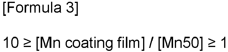
- The non-oriented electrical steel sheet of claim 1, wherein:
the steel sheet base material further includes 0.005 wt% or less of one or more of C, N, S, Ti, Nb, and V. - The non-oriented electrical steel sheet of claim 1, wherein:
the steel sheet base material further includes one or more of 0.01 to 0.2 wt% of Cu, 0.100 wt% or less of P, 0.002 wt% or less of B, 0.01 wt% or less of Mo, 0.005 wt% or less of Mg, and 0.005 wt% or less of Zr. - The non-oriented electrical steel sheet of claim 1, wherein:
an average crystal grain particle diameter before the stress relief annealing is 60 µm or less. - The non-oriented electrical steel sheet of claim 1, wherein:iron loss W10/800(W/kg) after the stress relief annealing satisfies the following Formula 4:wherein t is a thickness (mm) of the steel sheet.

- The non-oriented electrical steel sheet of claim 1, wherein:
the stress relief annealing is performed at a temperature of 800°C to 900°C under an atmosphere which includes one or more of nitrogen, hydrogen, and carbon monoxide and has a dew point of 0°C or lower. - A method for manufacturing a non-oriented electrical steel sheet, the method comprising:hot rolling a slab which includes, by weight: 2.0 to 6.5% of Si, 0.1 to 1.3% of Al, 0.3 to 2.0% of Mn, 0.03% or less (excluding 0%) of Sn, and 0.02% or less (excluding 0%) of Sb, with a balance of Fe and other inevitable impurities and satisfies the following Formula 1, thereby manufacturing a hot rolled sheet;removing scale present on a surface of the hot rolled sheet;cold rolling the descaled hot rolled sheet to manufacture a cold rolled sheet; andannealing the cold rolled sheet,wherein the removing of scale includes projecting shot balls in an amount of 15 to 35 kg/(min·m2) onto the steel sheet to remove scale:wherein [Sn] and [Sb] are contents (wt%) of Sn and Sb, respectively.

- The method for manufacturing a non-oriented electrical steel sheet of claim 7, wherein:
the shot balls have an average particle size of 0.1 to 1 mm and are projected for 1 to 60 seconds. - The method for manufacturing a non-oriented electrical steel sheet of claim 7, wherein:
a material of the shot balls is an Fe-based alloy. - The method for manufacturing a non-oriented electrical steel sheet of claim 7, wherein:
the annealing of the cold rolled sheet is performed at a temperature of 700 to 1100°C for 10 to 1000 seconds. - The method for manufacturing a non-oriented electrical steel sheet of claim 7, further comprising:
annealing the hot rolled sheet, before the removing of scale. - The method for manufacturing a non-oriented electrical steel sheet of claim 7, further comprising:
performing stress relief annealing, after the annealing of the cold rolled sheet. - A motor core comprising: a rotor formed by laminating a plurality of non-oriented electrical steel sheets and a stator formed by laminating a plurality of non-oriented electrical steel sheets,wherein the non-oriented electrical steel sheet in the rotor includes, by weight: 2.0 to 6.5% of Si, 0.1 to 1.3% of Al, 0.3 to 2.0% of Mn, 0.03% or less (excluding 0%) of Sn, and 0.02% or less (excluding 0%) of Sb, with a balance of Fe and other inevitable impurities, and satisfies the following Formulae 1 and 2, andthe non-oriented electrical steel sheet in the stator includes, by weight: 2.0 to 6.5% of Si, 0.1 to 1.3% of Al, 0.3 to 2.0% of Mn, 0.03% or less (excluding 0%) of Sn, and 0.02% or less (excluding 0%) of Sb, with a balance of Fe and other inevitable impurities, and satisfies the following Formulae 1 to 3:wherein [Sn] and [Sb] are contents of Sn and Sb, respectively, [Mn coating film] is an average Mn content (wt%) in the insulating coating film, and [Mn50] is a Mn content (wt%) at a depth of 50 µm from the interface between the steel sheet base material and the insulating coating film toward the inside of the steel sheet base material.


- The motor core of claim 13, wherein:
the non-oriented electrical steel sheets included in the stator and the rotor are derived from the same coil. - The motor core of claim 13, wherein:
a difference in contents of Si, Al, and Mn between the non-oriented electrical steel sheets included in the stator and the rotor is 0.20 wt% or less.
Applications Claiming Priority (2)
| Application Number | Priority Date | Filing Date | Title |
|---|---|---|---|
| KR20210184608 | 2021-12-22 | ||
| PCT/KR2022/020963 WO2023121294A1 (en) | 2021-12-22 | 2022-12-21 | Non-oriented electrical steel sheet and motor core comprising same |
Publications (2)
| Publication Number | Publication Date |
|---|---|
| EP4455335A1 true EP4455335A1 (en) | 2024-10-30 |
| EP4455335A4 EP4455335A4 (en) | 2025-10-29 |
Family
ID=86903079
Family Applications (1)
| Application Number | Title | Priority Date | Filing Date |
|---|---|---|---|
| EP22911927.6A Pending EP4455335A4 (en) | 2021-12-22 | 2022-12-21 | NON-ORIENTED ELECTRO-STEEL SHEET AND MOTOR CORE WITH IT |
Country Status (7)
| Country | Link |
|---|---|
| US (1) | US20250066892A1 (en) |
| EP (1) | EP4455335A4 (en) |
| JP (1) | JP2025500985A (en) |
| KR (1) | KR20230096879A (en) |
| CN (1) | CN118647747A (en) |
| MX (1) | MX2024007792A (en) |
| WO (1) | WO2023121294A1 (en) |
Families Citing this family (2)
| Publication number | Priority date | Publication date | Assignee | Title |
|---|---|---|---|---|
| JPWO2025047016A1 (en) * | 2023-08-30 | 2025-03-06 | ||
| KR20260011843A (en) * | 2024-07-16 | 2026-01-26 | 현대제철 주식회사 | Non-oriented electrical steel sheet and method for manufacturing the same |
Family Cites Families (15)
| Publication number | Priority date | Publication date | Assignee | Title |
|---|---|---|---|---|
| JP3252700B2 (en) * | 1995-05-02 | 2002-02-04 | 住友金属工業株式会社 | Electrical steel sheet with excellent magnetic properties and punchability |
| JP3852227B2 (en) * | 1998-10-23 | 2006-11-29 | Jfeスチール株式会社 | Non-oriented electrical steel sheet and manufacturing method thereof |
| JP2005118902A (en) * | 2003-10-14 | 2005-05-12 | Jfe Steel Kk | Method for imparting surface roughness of metal plate |
| JP4267562B2 (en) * | 2004-12-06 | 2009-05-27 | 新日本製鐵株式会社 | Manufacturing method of high grade non-oriented electrical steel sheet |
| JP5565419B2 (en) * | 2012-01-13 | 2014-08-06 | 新日鐵住金株式会社 | Method for producing non-oriented electrical steel sheet |
| KR101701194B1 (en) * | 2015-12-23 | 2017-02-01 | 주식회사 포스코 | Non-oriented electrical steel sheet and method for manufacturing the same |
| BR112018075826B1 (en) * | 2016-08-05 | 2022-08-16 | Nippon Steel Corporation | NON-ORIENTED ELECTRIC STEEL SHEET, NON-ORIENTED ELECTRIC STEEL SHEET MANUFACTURING METHOD AND MOTOR CORE MANUFACTURING METHOD |
| CN110573643B (en) * | 2017-07-19 | 2020-10-27 | 日本制铁株式会社 | Non-oriented electrical steel sheet |
| US11025142B2 (en) * | 2018-09-06 | 2021-06-01 | Ford Global Technologies, Llc | Method for manufacturing electric machine |
| JP6866935B2 (en) * | 2018-10-31 | 2021-04-28 | Jfeスチール株式会社 | Manufacturing method of non-oriented electrical steel sheet |
| US12148555B2 (en) * | 2018-11-02 | 2024-11-19 | Nippon Steel Corporation | Non-oriented electrical steel sheet |
| EP3957758B1 (en) * | 2019-04-17 | 2025-08-06 | JFE Steel Corporation | Non-oriented electrical steel sheet |
| JP7056699B2 (en) * | 2019-08-30 | 2022-04-19 | Jfeスチール株式会社 | Non-oriented electrical steel sheet and its manufacturing method |
| WO2021117325A1 (en) * | 2019-12-09 | 2021-06-17 | Jfeスチール株式会社 | Non-oriented electromagnetic steel sheet, motor core, and methods respectively for manufacturing same |
| CN112080694A (en) * | 2020-08-31 | 2020-12-15 | 首钢智新迁安电磁材料有限公司 | Method for improving surface pickling quality of non-oriented high-grade electrical steel |
-
2022
- 2022-12-21 US US18/722,296 patent/US20250066892A1/en active Pending
- 2022-12-21 MX MX2024007792A patent/MX2024007792A/en unknown
- 2022-12-21 WO PCT/KR2022/020963 patent/WO2023121294A1/en not_active Ceased
- 2022-12-21 EP EP22911927.6A patent/EP4455335A4/en active Pending
- 2022-12-21 KR KR1020220180192A patent/KR20230096879A/en active Pending
- 2022-12-21 CN CN202280091997.9A patent/CN118647747A/en active Pending
- 2022-12-21 JP JP2024538215A patent/JP2025500985A/en active Pending
Also Published As
| Publication number | Publication date |
|---|---|
| WO2023121294A1 (en) | 2023-06-29 |
| MX2024007792A (en) | 2024-09-06 |
| US20250066892A1 (en) | 2025-02-27 |
| KR20230096879A (en) | 2023-06-30 |
| EP4455335A4 (en) | 2025-10-29 |
| JP2025500985A (en) | 2025-01-15 |
| CN118647747A (en) | 2024-09-13 |
Similar Documents
| Publication | Publication Date | Title |
|---|---|---|
| TWI717201B (en) | Non-directional electromagnetic steel sheet and manufacturing method thereof | |
| EP3656885B1 (en) | Non-oriented electrical steel sheet | |
| EP3992312A1 (en) | Method for producing non-oriented electromagnetic steel sheet, method for producing motor core, and motor core | |
| EP3572535B1 (en) | Method for manufacturing non-oriented electromagnetic steel plate, and method for manufacturing motor core | |
| KR101682284B1 (en) | Non-oriented electrical steel sheet | |
| EP3533890B1 (en) | Non-oriented electrical steel sheet and method for producing same | |
| JP5273235B2 (en) | Method for producing non-oriented electrical steel sheet | |
| EP3358027B1 (en) | Non-oriented electromagnetic steel sheet and manufacturing method of same | |
| EP3546609B1 (en) | Non-oriented electrical steel sheet and manufacturing method therefor | |
| WO2018147044A1 (en) | Method for producing non-oriented electromagnetic steel sheet, method for producing motor core, and motor core | |
| KR102513317B1 (en) | Non-oriented electrical steel sheet and method for manufacturing the same | |
| EP4455334A1 (en) | Non-oriented electrical steel sheet and method for manufacturing same | |
| EP4137600A1 (en) | Non-oriented electromagnetic steel sheet and method for manufacturing same | |
| CN111566245A (en) | Dual-orientation electrical steel sheet and method for manufacturing the same | |
| US20250066892A1 (en) | Non-oriented electrical steel sheet and motor core comprising same | |
| KR20230096878A (en) | Non-oriented electrical steel sheet, method for manufacturing the same and motor core comprising the same | |
| JP2026509715A (en) | Non-oriented electrical steel and method for manufacturing the non-oriented electrical steel. | |
| EP4137599A1 (en) | Non-oriented electromagnetic steel sheet and method for manufacturing same | |
| JP5028992B2 (en) | Non-oriented electrical steel sheet and manufacturing method thereof | |
| WO2020090156A1 (en) | Method for manufacturing non-oriented electromagnetic steel sheet | |
| EP4296381A1 (en) | Non-oriented electromagnetic steel sheet and manufacturing method therefor | |
| EP4455343A1 (en) | Non-oriented electrical steel sheet, method for manufacturing same, and motor core comprising same | |
| JP2004339603A (en) | High-strength non-oriented electrical steel sheet excellent in high-frequency magnetic properties and method for producing the same | |
| EP4632103A1 (en) | Hot-rolled non-oriented electrical steel sheet and method for manufacturing same | |
| WO2024166942A1 (en) | Non-oriented electromagnetic steel sheet, method for producing same, and rotary electric machine containing same |
Legal Events
| Date | Code | Title | Description |
|---|---|---|---|
| STAA | Information on the status of an ep patent application or granted ep patent |
Free format text: STATUS: THE INTERNATIONAL PUBLICATION HAS BEEN MADE |
|
| PUAI | Public reference made under article 153(3) epc to a published international application that has entered the european phase |
Free format text: ORIGINAL CODE: 0009012 |
|
| STAA | Information on the status of an ep patent application or granted ep patent |
Free format text: STATUS: REQUEST FOR EXAMINATION WAS MADE |
|
| 17P | Request for examination filed |
Effective date: 20240718 |
|
| AK | Designated contracting states |
Kind code of ref document: A1 Designated state(s): AL AT BE BG CH CY CZ DE DK EE ES FI FR GB GR HR HU IE IS IT LI LT LU LV MC ME MK MT NL NO PL PT RO RS SE SI SK SM TR |
|
| DAV | Request for validation of the european patent (deleted) | ||
| DAX | Request for extension of the european patent (deleted) | ||
| REG | Reference to a national code |
Ref country code: DE Ref legal event code: R079 Free format text: PREVIOUS MAIN CLASS: C22C0038020000 Ipc: C21D0001300000 |
|
| A4 | Supplementary search report drawn up and despatched |
Effective date: 20250929 |
|
| RIC1 | Information provided on ipc code assigned before grant |
Ipc: C21D 1/30 20060101AFI20250923BHEP Ipc: C21D 1/76 20060101ALI20250923BHEP Ipc: C21D 6/00 20060101ALI20250923BHEP Ipc: C21D 7/06 20060101ALI20250923BHEP Ipc: C21D 8/12 20060101ALI20250923BHEP Ipc: C21D 9/46 20060101ALI20250923BHEP Ipc: C22C 38/00 20060101ALI20250923BHEP Ipc: C22C 38/02 20060101ALI20250923BHEP Ipc: C22C 38/04 20060101ALI20250923BHEP Ipc: C22C 38/06 20060101ALI20250923BHEP Ipc: C22C 38/12 20060101ALI20250923BHEP Ipc: C22C 38/14 20060101ALI20250923BHEP Ipc: C22C 38/16 20060101ALI20250923BHEP Ipc: C22C 38/20 20060101ALI20250923BHEP Ipc: C22C 38/60 20060101ALI20250923BHEP Ipc: C23C 22/20 20060101ALI20250923BHEP Ipc: C23C 22/74 20060101ALI20250923BHEP Ipc: H02K 15/02 20060101ALI20250923BHEP Ipc: H01F 1/18 20060101ALI20250923BHEP Ipc: H01F 1/147 20060101ALI20250923BHEP |