WO2018147044A1 - Method for producing non-oriented electromagnetic steel sheet, method for producing motor core, and motor core - Google Patents
Method for producing non-oriented electromagnetic steel sheet, method for producing motor core, and motor core Download PDFInfo
- Publication number
- WO2018147044A1 WO2018147044A1 PCT/JP2018/001533 JP2018001533W WO2018147044A1 WO 2018147044 A1 WO2018147044 A1 WO 2018147044A1 JP 2018001533 W JP2018001533 W JP 2018001533W WO 2018147044 A1 WO2018147044 A1 WO 2018147044A1
- Authority
- WO
- WIPO (PCT)
- Prior art keywords
- mass
- less
- steel sheet
- annealing
- oriented electrical
- Prior art date
Links
Images

Classifications
-
- C—CHEMISTRY; METALLURGY
- C21—METALLURGY OF IRON
- C21D—MODIFYING THE PHYSICAL STRUCTURE OF FERROUS METALS; GENERAL DEVICES FOR HEAT TREATMENT OF FERROUS OR NON-FERROUS METALS OR ALLOYS; MAKING METAL MALLEABLE, e.g. BY DECARBURISATION OR TEMPERING
- C21D8/00—Modifying the physical properties by deformation combined with, or followed by, heat treatment
- C21D8/12—Modifying the physical properties by deformation combined with, or followed by, heat treatment during manufacturing of articles with special electromagnetic properties
- C21D8/1216—Modifying the physical properties by deformation combined with, or followed by, heat treatment during manufacturing of articles with special electromagnetic properties the working step(s) being of interest
- C21D8/1222—Hot rolling
-
- C—CHEMISTRY; METALLURGY
- C22—METALLURGY; FERROUS OR NON-FERROUS ALLOYS; TREATMENT OF ALLOYS OR NON-FERROUS METALS
- C22C—ALLOYS
- C22C38/00—Ferrous alloys, e.g. steel alloys
- C22C38/004—Very low carbon steels, i.e. having a carbon content of less than 0,01%
-
- C—CHEMISTRY; METALLURGY
- C21—METALLURGY OF IRON
- C21D—MODIFYING THE PHYSICAL STRUCTURE OF FERROUS METALS; GENERAL DEVICES FOR HEAT TREATMENT OF FERROUS OR NON-FERROUS METALS OR ALLOYS; MAKING METAL MALLEABLE, e.g. BY DECARBURISATION OR TEMPERING
- C21D1/00—General methods or devices for heat treatment, e.g. annealing, hardening, quenching or tempering
- C21D1/26—Methods of annealing
- C21D1/30—Stress-relieving
-
- C—CHEMISTRY; METALLURGY
- C21—METALLURGY OF IRON
- C21D—MODIFYING THE PHYSICAL STRUCTURE OF FERROUS METALS; GENERAL DEVICES FOR HEAT TREATMENT OF FERROUS OR NON-FERROUS METALS OR ALLOYS; MAKING METAL MALLEABLE, e.g. BY DECARBURISATION OR TEMPERING
- C21D8/00—Modifying the physical properties by deformation combined with, or followed by, heat treatment
- C21D8/12—Modifying the physical properties by deformation combined with, or followed by, heat treatment during manufacturing of articles with special electromagnetic properties
- C21D8/1216—Modifying the physical properties by deformation combined with, or followed by, heat treatment during manufacturing of articles with special electromagnetic properties the working step(s) being of interest
- C21D8/1233—Cold rolling
-
- C—CHEMISTRY; METALLURGY
- C21—METALLURGY OF IRON
- C21D—MODIFYING THE PHYSICAL STRUCTURE OF FERROUS METALS; GENERAL DEVICES FOR HEAT TREATMENT OF FERROUS OR NON-FERROUS METALS OR ALLOYS; MAKING METAL MALLEABLE, e.g. BY DECARBURISATION OR TEMPERING
- C21D8/00—Modifying the physical properties by deformation combined with, or followed by, heat treatment
- C21D8/12—Modifying the physical properties by deformation combined with, or followed by, heat treatment during manufacturing of articles with special electromagnetic properties
- C21D8/1244—Modifying the physical properties by deformation combined with, or followed by, heat treatment during manufacturing of articles with special electromagnetic properties the heat treatment(s) being of interest
- C21D8/1272—Final recrystallisation annealing
-
- C—CHEMISTRY; METALLURGY
- C22—METALLURGY; FERROUS OR NON-FERROUS ALLOYS; TREATMENT OF ALLOYS OR NON-FERROUS METALS
- C22C—ALLOYS
- C22C38/00—Ferrous alloys, e.g. steel alloys
- C22C38/001—Ferrous alloys, e.g. steel alloys containing N
-
- C—CHEMISTRY; METALLURGY
- C22—METALLURGY; FERROUS OR NON-FERROUS ALLOYS; TREATMENT OF ALLOYS OR NON-FERROUS METALS
- C22C—ALLOYS
- C22C38/00—Ferrous alloys, e.g. steel alloys
- C22C38/002—Ferrous alloys, e.g. steel alloys containing In, Mg, or other elements not provided for in one single group C22C38/001 - C22C38/60
-
- C—CHEMISTRY; METALLURGY
- C22—METALLURGY; FERROUS OR NON-FERROUS ALLOYS; TREATMENT OF ALLOYS OR NON-FERROUS METALS
- C22C—ALLOYS
- C22C38/00—Ferrous alloys, e.g. steel alloys
- C22C38/005—Ferrous alloys, e.g. steel alloys containing rare earths, i.e. Sc, Y, Lanthanides
-
- C—CHEMISTRY; METALLURGY
- C22—METALLURGY; FERROUS OR NON-FERROUS ALLOYS; TREATMENT OF ALLOYS OR NON-FERROUS METALS
- C22C—ALLOYS
- C22C38/00—Ferrous alloys, e.g. steel alloys
- C22C38/008—Ferrous alloys, e.g. steel alloys containing tin
-
- C—CHEMISTRY; METALLURGY
- C22—METALLURGY; FERROUS OR NON-FERROUS ALLOYS; TREATMENT OF ALLOYS OR NON-FERROUS METALS
- C22C—ALLOYS
- C22C38/00—Ferrous alloys, e.g. steel alloys
- C22C38/02—Ferrous alloys, e.g. steel alloys containing silicon
-
- C—CHEMISTRY; METALLURGY
- C22—METALLURGY; FERROUS OR NON-FERROUS ALLOYS; TREATMENT OF ALLOYS OR NON-FERROUS METALS
- C22C—ALLOYS
- C22C38/00—Ferrous alloys, e.g. steel alloys
- C22C38/04—Ferrous alloys, e.g. steel alloys containing manganese
-
- C—CHEMISTRY; METALLURGY
- C22—METALLURGY; FERROUS OR NON-FERROUS ALLOYS; TREATMENT OF ALLOYS OR NON-FERROUS METALS
- C22C—ALLOYS
- C22C38/00—Ferrous alloys, e.g. steel alloys
- C22C38/06—Ferrous alloys, e.g. steel alloys containing aluminium
-
- C—CHEMISTRY; METALLURGY
- C22—METALLURGY; FERROUS OR NON-FERROUS ALLOYS; TREATMENT OF ALLOYS OR NON-FERROUS METALS
- C22C—ALLOYS
- C22C38/00—Ferrous alloys, e.g. steel alloys
- C22C38/12—Ferrous alloys, e.g. steel alloys containing tungsten, tantalum, molybdenum, vanadium, or niobium
-
- C—CHEMISTRY; METALLURGY
- C22—METALLURGY; FERROUS OR NON-FERROUS ALLOYS; TREATMENT OF ALLOYS OR NON-FERROUS METALS
- C22C—ALLOYS
- C22C38/00—Ferrous alloys, e.g. steel alloys
- C22C38/14—Ferrous alloys, e.g. steel alloys containing titanium or zirconium
-
- C—CHEMISTRY; METALLURGY
- C22—METALLURGY; FERROUS OR NON-FERROUS ALLOYS; TREATMENT OF ALLOYS OR NON-FERROUS METALS
- C22C—ALLOYS
- C22C38/00—Ferrous alloys, e.g. steel alloys
- C22C38/16—Ferrous alloys, e.g. steel alloys containing copper
-
- C—CHEMISTRY; METALLURGY
- C22—METALLURGY; FERROUS OR NON-FERROUS ALLOYS; TREATMENT OF ALLOYS OR NON-FERROUS METALS
- C22C—ALLOYS
- C22C38/00—Ferrous alloys, e.g. steel alloys
- C22C38/18—Ferrous alloys, e.g. steel alloys containing chromium
-
- C—CHEMISTRY; METALLURGY
- C22—METALLURGY; FERROUS OR NON-FERROUS ALLOYS; TREATMENT OF ALLOYS OR NON-FERROUS METALS
- C22C—ALLOYS
- C22C38/00—Ferrous alloys, e.g. steel alloys
- C22C38/18—Ferrous alloys, e.g. steel alloys containing chromium
- C22C38/34—Ferrous alloys, e.g. steel alloys containing chromium with more than 1.5% by weight of silicon
-
- C—CHEMISTRY; METALLURGY
- C22—METALLURGY; FERROUS OR NON-FERROUS ALLOYS; TREATMENT OF ALLOYS OR NON-FERROUS METALS
- C22C—ALLOYS
- C22C38/00—Ferrous alloys, e.g. steel alloys
- C22C38/60—Ferrous alloys, e.g. steel alloys containing lead, selenium, tellurium, or antimony, or more than 0.04% by weight of sulfur
-
- H—ELECTRICITY
- H01—ELECTRIC ELEMENTS
- H01F—MAGNETS; INDUCTANCES; TRANSFORMERS; SELECTION OF MATERIALS FOR THEIR MAGNETIC PROPERTIES
- H01F1/00—Magnets or magnetic bodies characterised by the magnetic materials therefor; Selection of materials for their magnetic properties
- H01F1/01—Magnets or magnetic bodies characterised by the magnetic materials therefor; Selection of materials for their magnetic properties of inorganic materials
- H01F1/03—Magnets or magnetic bodies characterised by the magnetic materials therefor; Selection of materials for their magnetic properties of inorganic materials characterised by their coercivity
- H01F1/12—Magnets or magnetic bodies characterised by the magnetic materials therefor; Selection of materials for their magnetic properties of inorganic materials characterised by their coercivity of soft-magnetic materials
- H01F1/14—Magnets or magnetic bodies characterised by the magnetic materials therefor; Selection of materials for their magnetic properties of inorganic materials characterised by their coercivity of soft-magnetic materials metals or alloys
- H01F1/147—Alloys characterised by their composition
- H01F1/14766—Fe-Si based alloys
- H01F1/14775—Fe-Si based alloys in the form of sheets
-
- H—ELECTRICITY
- H01—ELECTRIC ELEMENTS
- H01F—MAGNETS; INDUCTANCES; TRANSFORMERS; SELECTION OF MATERIALS FOR THEIR MAGNETIC PROPERTIES
- H01F3/00—Cores, Yokes, or armatures
- H01F3/02—Cores, Yokes, or armatures made from sheets
-
- C—CHEMISTRY; METALLURGY
- C21—METALLURGY OF IRON
- C21D—MODIFYING THE PHYSICAL STRUCTURE OF FERROUS METALS; GENERAL DEVICES FOR HEAT TREATMENT OF FERROUS OR NON-FERROUS METALS OR ALLOYS; MAKING METAL MALLEABLE, e.g. BY DECARBURISATION OR TEMPERING
- C21D9/00—Heat treatment, e.g. annealing, hardening, quenching or tempering, adapted for particular articles; Furnaces therefor
- C21D9/46—Heat treatment, e.g. annealing, hardening, quenching or tempering, adapted for particular articles; Furnaces therefor for sheet metals
-
- C—CHEMISTRY; METALLURGY
- C22—METALLURGY; FERROUS OR NON-FERROUS ALLOYS; TREATMENT OF ALLOYS OR NON-FERROUS METALS
- C22C—ALLOYS
- C22C2202/00—Physical properties
- C22C2202/02—Magnetic
Definitions
- the present invention relates to a method for manufacturing a non-oriented electrical steel sheet, a method for manufacturing a motor core, and a motor core.
- the present invention relates to a motor core manufacturing method using a conductive magnetic steel sheet and a motor core.
- the motor core is divided into a fixed stator core and a rotating rotor core, and in a rotor core such as a HEV drive motor having a large outer diameter, a very large centrifugal force acts by high-speed rotation.
- a rotor core such as a HEV drive motor having a large outer diameter
- the rotor core has a very narrow portion (1-2 mm) called a rotor core bridge portion depending on the structure. Therefore, the non-oriented electrical steel sheet used for the rotor core is required to have higher strength than conventional materials.
- the material used for the stator core is required to have high magnetic flux density and low iron loss.
- non-oriented electrical steel sheets used for motor cores must have high strength for rotor cores, and high magnetic flux density and low iron loss for one stator core. Is ideal.
- the required characteristics differ greatly between the rotor core and the stator core, but in order to increase the manufacturability and material yield of the motor core, It is desirable to simultaneously extract a rotor core material and a stator core material from the same material, and laminate them to assemble the rotor core or stator core.
- motors in particular, stator cores
- strain relief annealing in order to improve magnetic characteristics.
- the magnetic flux density after the stress relief annealing tends to decrease. Admitted.
- such a steel plate has a problem that it is not preferable as a steel plate for a stator that requires a particularly high torque.
- Patent Document 1 discloses a motor core in which a rotor and a stator are punched and laminated from the same steel sheet, and only the stator is subjected to strain relief annealing.
- the plate thickness used in the construction method is 0.15 mm or more and 0.35 mm or less, the yield strength of the steel sheet before strain relief annealing is 600 MPa or more, and the iron loss W 10/400 after strain relief annealing is 20 W / kg or less.
- Non-oriented electrical steel sheets have been proposed.
- Patent Document 1 reduces the impurity elements such as Ti, S, N, V, Nb, Zr, and As contained in the steel to an extremely low level in order to promote crystal grain growth in strain relief annealing. Further, 0.5 to 3 mass% of Ni is added. However, Ni is a very expensive raw material. Moreover, in the above-mentioned Patent Document 1, no study is made on the magnetic flux density after strain relief annealing.
- the present invention has been made in view of the above prior art, and the purpose thereof is high strength after finish annealing without adding expensive Ni, and excellent magnetic properties after strain relief annealing.
- the present invention is to propose a method for producing a non-oriented electrical steel sheet with a small decrease in magnetic flux density, a method for producing a motor core using the steel sheet, and a motor core.
- the inventors made extensive studies by paying attention to the influence of the component composition and production conditions on the magnetic flux density B 50 after strain relief annealing. As a result, it is possible to increase the strength of the steel sheet after finish annealing by reducing the impurity elements in the steel as much as possible, and increasing the Si content. By applying strain relief annealing higher than the prior art, it is possible to impart a magnetic property with a small decrease in magnetic flux density and low iron loss.
- stator core material having a low iron loss and a high magnetic flux density can be collected at the same time, and has led to the development of the present invention.
- C 0.0050 mass% or less, Si: 2-7 mass%, Mn: 0.05-2.0 mass%, P: 0.2 mass% or less, S: 0.005 mass% or less, Al: 3 mass% or less, N: 0.005 mass% or less, Ti: 0.003 mass% or less, Nb: 0.005 mass% or less, and V: 0.005 mass% or less, with the balance being Fe and inevitable impurities
- a steel slab having a component composition is hot-rolled, cold-rolled, finish-annealed, and strain-annealed.
- the yield stress of finishing the steel sheet after annealing is higher 400 MPa, the finishing ratio of magnetic flux density B 50S after subjected to stress relief annealing the steel sheet after the final annealing for the magnetic flux density B 50H of the steel sheet after annealing (B 50S /
- B 50S / We propose a method for producing a non-oriented electrical steel sheet characterized by adjusting the conditions of finish annealing and strain relief annealing so that B 50H ) is 0.99 or more.
- the steel slab used in the method for producing the non-oriented electrical steel sheet of the present invention further includes the following groups A to C; Group A; one or two selected from Sn: 0.005 to 0.20 mass% and Sb: 0.005 to 0.20 mass% Group B; Ca: 0.001 to 0.010 mass%, Mg: 0. One or more selected from 001 to 0.010 mass% and REM: 0.001 to 0.010 mass% Group C: Cr: 0.01 to 0.5 mass% and Cu: 0.01 to 0.00. It contains at least one group of 1 type or 2 types selected from 2 mass%.
- the manufacturing method of the said non-oriented electrical steel sheet of this invention is based on the conditions of the said stress relief annealing, and iron loss W10 / 400 (W / kg) after stress relief annealing is sheet thickness t (mm).
- W 10/400 ⁇ 10 + 25t (1) It adjusts so that it may satisfy
- the non-oriented electrical steel sheet production method of the present invention includes the above-described conditions for strain relief annealing, wherein the soaking temperature is 750 to 950 ° C., the soaking time is 0.1 to 10 hr, and the soaking temperature is from 600 ° C. The rate of temperature increase up to 8 ° C./min or more.
- the present invention is a method for manufacturing a motor core in which the rotor core material and the stator core material are collected from the same material, C: 0.0050 mass% or less, Si: 2-7 mass%, Mn: 0.05-2.0 mass%, P: 0.2 mass% or less, S: 0.005 mass% or less, Al: 3 mass% or less, N: 0.005 mass% or less, Ti: 0.003 mass% or less, Nb: 0.005 mass% or less, and V: 0.00.
- a non-oriented electrical steel sheet containing 005 mass% or less, the balance being Fe and inevitable impurities, and having a yield stress of 400 MPa or more is used as a rotor core, and the non-oriented electrical steel sheet is subjected to strain relief annealing to form a stator core, the ratio of the magnetic flux density B 50S of the stator core with respect to the magnetic flux density B 50H of the rotor core (B 50S / B 50 ) Proposes a motor core manufacturing method characterized by a 0.99 or more.
- the non-oriented electrical steel sheet used in the method for manufacturing the motor core of the present invention further includes the following groups A to C; Group A; one or two selected from Sn: 0.005 to 0.20 mass% and Sb: 0.005 to 0.20 mass% Group B; Ca: 0.001 to 0.010 mass%, Mg: 0. One or more selected from 001 to 0.010 mass% and REM: 0.001 to 0.010 mass% Group C: Cr: 0.01 to 0.5 mass% and Cu: 0.01 to 0.00. It contains at least one group of 1 type or 2 types selected from 2 mass%.
- the manufacturing method of the said motor core of this invention is based on the conditions of the said stress relief annealing, and the iron loss W10 / 400 (W / kg) after strain relief annealing is the following in relation with plate
- the motor core manufacturing method includes the above-described strain relief annealing conditions: a soaking temperature of 750 to 950 ° C., a soaking time of 0.1 to 10 hours, and a heating rate from 600 ° C. to the soaking temperature. Is 8 ° C./min or more.
- the present invention is a motor core made of a non-oriented electrical steel sheet in which the rotor core material and the stator core material are the same, C: 0.0050 mass% or less, Si: 2 to 7 mass%, Mn: 0.05 to 2.0 mass% , P: 0.2 mass% or less, S: 0.005 mass% or less, Al: 3 mass% or less, N: 0.005 mass% or less, Ti: 0.003 mass% or less, Nb: 0.005 mass% or less, and V: 0 contained the following .005Mass%, the balance being Fe and unavoidable impurities, the yield stress of the rotor core material is not less than 400 MPa, and the ratio of the magnetic flux density B 50S of the stator core with respect to the magnetic flux density B 50H of the rotor core (B 50S / B50H ) is a 0.99 or more motor core.
- the non-oriented electrical steel sheet used for the motor core of the present invention further includes the following groups A to C; Group A; one or two selected from Sn: 0.005 to 0.20 mass% and Sb: 0.005 to 0.20 mass% Group B; Ca: 0.001 to 0.010 mass%, Mg: 0. One or more selected from 001 to 0.010 mass% and REM: 0.001 to 0.010 mass% Group C: Cr: 0.01 to 0.5 mass% and Cu: 0.01 to 0.00. It contains at least one group of 1 type or 2 types selected from 2 mass%.
- stator core material used for the motor core of the present invention has an iron loss W 10/400 (W / kg) of the following formula (1) in relation to the plate thickness t (mm): W 10/400 ⁇ 10 + 25t (1) It is characterized by satisfying.
- the present invention it is possible to provide a non-oriented electrical steel sheet that has high strength after finish annealing and a small decrease in magnetic flux density due to strain relief annealing. Therefore, according to this invention, it becomes possible to extract
- C 0.0022 mass%, Si: 3.1 mass%, Mn: 0.54 mass%, P: 0 in order to investigate the influence of the temperature rising rate during the stress relief annealing on the magnetic flux density B 50 after the stress relief annealing. .01 mass%, S: 0.0016 mass%, Al: 0.6 mass%, N: 0.0018 mass%, O: 0.0023 mass%, Ti: 0.0014 mass%, Nb: 0.0006 mass%, and V: 0.00. Steel containing 0015 mass% is melted in a vacuum furnace to form a steel ingot, and then hot rolled to obtain a hot rolled sheet having a thickness of 2.0 mm.
- the hot rolled sheet is annealed at 950 ° C. ⁇ 30 seconds. Then, pickling and cold rolling to form a cold-rolled sheet having a thickness of 0.25 mm, and the cold-rolled sheet is 850 ° C. in a non-oxidizing atmosphere of 20 vol% H 2 -80 vol% N 2 Hold for 10 seconds at the temperature of Was a non-oriented electrical steel sheet is subjected to that finish annealing.
- the steel sheet after the final annealing the magnetic flux density was measured B 50 at 25cm Epstein method.
- the magnetic flux density after the finish annealing is also referred to as “B 50H ”.
- the yield stress was 480 MPa.
- the Epstein test piece was subjected to strain relief annealing at 825 ° C. ⁇ 2 hr in an N 2 atmosphere, and the magnetic flux density B 50 was again measured by the 25 cm Epstein method.
- the temperature rising rate between 600 to 825 ° C. was variously changed in the range of 1 to 50 ° C./min.
- the magnetic flux density after the strain relief annealing is also expressed as “B 50S ”.
- FIG. 1 shows the relationship between the rate of temperature increase between 600 and 825 ° C. in strain relief annealing and the ratio of the magnetic flux density after strain relief annealing to the magnetic flux density after finish annealing (B 50S / B 50H ). From this figure, it can be seen that by increasing the rate of temperature increase during strain relief annealing to 8 ° C./min or more, the decrease in magnetic flux density during strain relief annealing is suppressed. This is because, by increasing the rate of temperature increase, the ⁇ 100 ⁇ and ⁇ 110 ⁇ orientation grain growth preferable for the magnetic properties during strain relief annealing is promoted, and the ⁇ 111 ⁇ orientation grain that causes a decrease in magnetic flux density. This is probably because growth was suppressed.
- C 0.0050 mass% or less
- C is a harmful element that forms carbides, causes magnetic aging, and deteriorates the iron loss characteristics of the product plate. Therefore, the upper limit is limited to 0.0050 mass%. Preferably it is 0.0030 mass% or less. C is preferably as low as possible, and the lower limit is not particularly defined.
- Si 2 to 7 mass%
- Si is an element that increases the specific resistance of the steel and reduces iron loss, and also enhances the strength of the steel by solid solution strengthening, so 2 mass% or more is added. However, if it exceeds 7 mass%, it becomes difficult to roll, so the upper limit of Si is 7 mass%.
- the range is preferably 2.5 to 6.5 mass%, more preferably 3.0 to 6.0 mass%.
- Mn 0.05 to 2.0 mass% Mn, like Si, is an element effective in increasing the specific resistance and strength of steel and preventing hot brittleness caused by S. Therefore, in this invention, 0.05 mass% or more is added. However, if the added amount exceeds 2.0 mass%, the operability in steelmaking deteriorates, so the upper limit is made 2.0 mass%.
- the range is preferably from 0.1 to 1.5 mass%, more preferably from 0.1 to 1.0 mass%.
- P 0.2 mass% or less P is an element used for adjusting the strength (hardness) of steel because of its high solid solution strengthening ability. However, if it exceeds 0.2 mass%, the steel becomes brittle and rolled. Therefore, the upper limit is set to 0.2 mass%. The lower limit is not specified. The range is preferably 0.001 to 0.15 mass%, more preferably 0.001 to 0.10 mass%.
- Al 3 mass% or less Al is effective in increasing the specific resistance of steel and reducing iron loss. However, since it will become difficult to roll when it exceeds 3 mass%, an upper limit shall be 3 mass%. However, when the Al content is in the range of more than 0.01 mass% and less than 0.1 mass%, fine AlN precipitates and iron loss increases, so the preferable range of Al is 0.01 mass% or less, or 0.1 It is in the range of ⁇ 2.0 mass%. In particular, when Al is reduced, the texture can be improved and the magnetic flux density can be increased. Therefore, when the above effect is emphasized, Al is preferably set to 0.01 mass% or less. More preferably, it is 0.003 mass% or less.
- each 0.005 mass% or less S, N, Nb and V all generate fine precipitates such as carbides, nitrides and sulfides and inhibit grain growth during strain relief annealing.
- it is a harmful element that increases iron loss.
- the upper limit of the element is 0.005 mass%.
- each is 0.003 mass% or less.
- Ti 0.003 mass% or less
- Ti is a harmful element that generates and precipitates fine carbonitride and the like, inhibits grain growth during stress relief annealing, and increases iron loss.
- 0.003 mass% If it exceeds, the adverse effect becomes significant, so the upper limit is made 0.003 mass%.
- it is 0.002 mass% or less.
- the non-oriented electrical steel sheet of the present invention can further contain the following components in addition to the above basic components.
- Sn, Sb 0.005 to 0.20 mass% each Sn and Sb have the effect of improving the recrystallization texture and improving the magnetic flux density and iron loss characteristics. In order to acquire the said effect, addition of 0.005 mass% or more is required respectively. On the other hand, even if the total exceeds 0.20 mass%, the above effect is saturated. Therefore, when adding Sn and Sb, it is preferable to set the content in the range of 0.005 to 0.20 mass%, respectively. More preferably, it is in the range of 0.01 to 0.05 mass%.
- Ca, Mg, REM 0.001 to 0.010 mass% each Ca, Mg and REM have the effect of forming stable sulfides and selenides and improving the grain growth during strain relief annealing.
- addition of 0.001 mass% or more is required,
- Ca, Mg, REM Is preferably added in the range of 0.001 to 0.010 mass%. More preferably, each is in the range of 0.002 to 0.005 mass%.
- Cr 0.01 to 0.5 mass% Cr has the effect of increasing the specific resistance and decreasing the iron loss. In order to acquire the said effect, it is necessary to contain 0.01 mass% or more. On the other hand, if it exceeds 0.5 mass%, the raw material cost increases, which is not preferable. Therefore, when adding Cr, it is preferable to add in the range of 0.01 to 0.5 mass%. More preferably, it is in the range of 0.1 to 0.4 mass%.
- Cu 0.01 to 0.2 mass%
- Cu has the effect of improving the texture and improving the magnetic flux density. In order to acquire the said effect, addition of 0.01 mass% or more is required. On the other hand, if it exceeds 0.2 mass%, the above effect is saturated. Therefore, when adding Cu, it is preferable to add in the range of 0.01 to 0.2 mass%. More preferably, it is in the range of 0.05 to 0.15 mass%.
- the balance other than the above components is Fe and inevitable impurities.
- yield stress after finish annealing 400 MPa or more
- the yield stress needs to be 400 MPa or more. If it is less than 400 MPa, there is a possibility that it cannot withstand the centrifugal force caused by the high-speed rotation received by the HEV drive motor or the like.
- a preferred yield stress is 450 MPa or more.
- the said yield stress means the upper yield point when a tensile test is carried out in the rolling direction of a steel plate.
- the test piece and test conditions used for a tensile test should just conform to JIS.
- the non-oriented electrical steel sheet of the present invention is characterized by a small decrease in magnetic properties, particularly magnetic flux density, due to strain relief annealing, specifically, before strain relief annealing. It is necessary that the ratio of the magnetic flux density B 50S after stress relief annealing for the magnetic flux density B 50H (B 50S / B 50H ) is 0.99 or more. This is because if (B 50S / B 50H ) is less than 0.99, the required torque will not be achieved as a stator application. Preferred B 50S / B 50H is 0.995 or more.
- Iron loss W 10/400 after strain relief annealing 10 + 25 t (mm) or less
- the above-described strain relief annealing applied to the steel sheet after the finish annealing is performed by increasing the soaking temperature from 750 to 950 ° C., the soaking time from 0.1 to 10 hours, and from 600 ° C. to the above soaking temperature. It is assumed that the temperature rate is 8 ° C./min or more.
- the stress relief annealing is generally performed after being assembled into a core shape, and the magnetic characteristics after stress relief annealing cannot be directly measured.
- the magnetic flux density B 50S and the iron loss W 10/400 after the stress relief annealing are the magnetic flux density and iron after the heat treatment is performed on the steel sheet after the finish annealing under conditions simulating the stress relief annealing. Substitute with loss.
- a more preferable soaking temperature is 800 to 900 ° C.
- a soaking time is 0.5 to 2 hours
- a more preferable heating rate is 10 ° C./min or more.
- the non-oriented electrical steel sheet of the present invention is obtained by melting a steel having the above composition suitable for the present invention by a generally known refining process using a converter, an electric furnace, a vacuum degassing apparatus, etc. After forming a steel slab by the ingot-bundling rolling method, the steel slab is hot-rolled by a generally known method to form a hot-rolled sheet, and the hot-rolled sheet is subjected to hot-rolled sheet annealing as necessary It can be manufactured by cold rolling and finish annealing.
- the soaking temperature is preferably in the range of 800 to 1100 ° C. If the temperature is less than 800 ° C., the effect of hot-rolled sheet annealing is small and a sufficient effect of improving magnetic properties cannot be obtained. On the other hand, if the temperature exceeds 1100 ° C., not only is the cost disadvantageous, but the crystal grains become coarse, This is to promote brittle fracture during hot rolling.
- a more preferred soaking temperature for hot-rolled sheet annealing is in the range of 850 to 1000 ° C.
- the cold rolling after hot rolling or after hot-rolled sheet annealing is preferably performed once or twice or more with intermediate annealing interposed therebetween.
- the cold rolling (final cold rolling) with the final thickness is preferably warm rolling at 200 ° C. or higher from the viewpoint of increasing the magnetic flux density.
- the final plate thickness in the cold rolling is preferably in the range of 0.1 to 0.3 mm. If it is less than 0.1 mm, the productivity is lowered, and if it exceeds 0.3 mm, the effect of reducing iron loss is small. More preferably, it is in the range of 0.15 to 0.27 mm.
- the finish annealing applied to the cold-rolled sheet having the final thickness is preferably continuous annealing in the range of 700 to 1000 ° C. for 1 to 300 seconds. If the soaking temperature is less than 700 ° C., recrystallization does not proceed sufficiently and good magnetic properties cannot be obtained, and in addition, the shape correction effect in continuous annealing cannot be obtained sufficiently. On the other hand, if the temperature exceeds 1000 ° C., the crystal grain size becomes coarse and the steel sheet strength decreases. In order to give the steel sheet after finish annealing strength for rotor cores, the soaking temperature and soaking time in finish annealing are within the above range and within the range where iron loss characteristics and shape are allowed, as much as possible. A low temperature and a short time are desirable, and more preferable finish annealing conditions are 750 to 900 ° C. ⁇ 10 to 60 seconds.
- the steel sheet after the finish annealing is preferably coated with an insulating film on the surface in order to secure insulation during lamination and / or improve punchability.
- the insulating film is preferably an organic film containing a resin.
- a semi-organic or inorganic film is preferable. .
- the steel plate after finishing annealing or coated with an insulating film has a high yield strength of 400 MPa or more, so it is suitable as a material for a rotor core and processed into a core shape (rotor core material) by punching or the like. , Can be laminated to form a rotor core.
- the stator core is required to have a low iron loss and a high magnetic flux density
- the steel sheet is formed into a core (stator core material) shape by punching or the like, laminated to form a rotor core, and then subjected to strain relief annealing. It is preferable.
- the magnetic flux density B 50S after stress relief annealing for the magnetic flux density B 50H before stress relief annealing ratio (B 50S / B 50H) of 0.99 or more In order to satisfy the conditions stably, it is necessary to simultaneously extract the stator core material and the rotor core material from the same steel plate. This is because if the stator core material and the rotor core material are collected from different materials, the probability that (B 50S / B 50H ) will be less than 0.99 increases.
- the strain relief annealing is preferably performed in an inert gas atmosphere under the conditions of 750 to 950 ° C. ⁇ 0.1 to 10 hr, and 800 to 900 ° C. ⁇ 0.5 to 2 hr. More preferably.
- the annealing temperature is less than 750 ° C. and / or the annealing time is less than 0.1 hr, the grain growth is insufficient, and the effect of improving the iron loss after strain relief annealing cannot be obtained, while the annealing temperature exceeds 950 ° C. and When the annealing time exceeds 10 hours, the insulating coating is destroyed, so that it is difficult to ensure the insulation between the steel plates, and the iron loss increases.
- the rate of temperature increase from 600 ° C. to the strain relief annealing temperature is 8 ° C./min or more. More preferably, it is 10 ° C./min or more.
- the non-oriented electrical steel sheet according to the present invention has a high yield stress after finish annealing and a small decrease in magnetic flux density during strain relief annealing. Therefore, it is possible to manufacture both a rotor core that requires high strength and a stator core that requires low iron loss and high magnetic flux density.
- L: 280 mm ⁇ C: 30 mm L direction (rolling direction) sample and C: 280 mm ⁇ L: 30 mm C direction sample (perpendicular to the rolling direction) were cut out from the steel plate after the finish annealing, and the Epstein test was performed. And magnetic flux density B 50H was measured. Further, a JIS No. 13 tensile test piece was also collected from the L direction of the finish annealed plate and subjected to a tensile test. Next, the test piece after the Epstein test was subjected to heat treatment simulating the temperature increase rate, the soaking temperature, and the soaking time annealing of the soaking time shown in Table 2 in an N 2 atmosphere, and then the Epstein test was performed again. performed by measuring the magnetic flux density B 50S after stress relief annealing, it was calculated the ratio between the B 50H. At the same time, the iron loss W 10/400 after strain relief annealing was also measured.
- the non-oriented electrical steel sheet produced by the method of the present invention has high strength after finish annealing, and has excellent magnetic properties of low iron loss and high magnetic flux density after strain relief annealing. It turns out that it has the characteristic suitable for using in motor cores, such as a motor for HEV drive.
- a pair of rotor cores and stator cores are prepared from each of the non-oriented electrical steel sheets after the finish annealing, and the assembled stator cores are heated to 600 ° C. to 850 ° C. at 10 ° C./min in an N 2 atmosphere. The temperature was raised and subjected to strain relief annealing that was held at 850 ° C. for 1 hr, and then assembled into one IPM motor, and the motor efficiency was measured. Note that the IPM motor used for the above measurement has a stator outer diameter of 150 mm, a stack thickness of 25 mm, and a motor output of 300 W. Measurement conditions were driven at 1500 rpm and 2 Nm, and the motor efficiency at the same output was measured. The measurement results are also shown in Table 2. From this result, it can be seen that the motor manufactured from the steel plate of the present invention has a stable and high motor efficiency.
Abstract
Description
上記仕上焼鈍後の鋼板の降伏応力が400MPa以上、上記仕上焼鈍後の鋼板の磁束密度B50Hに対する上記仕上焼鈍後の鋼板に歪取焼鈍を施した後の磁束密度B50Sの比(B50S/B50H)が0.99以上となるように仕上焼鈍および歪取焼鈍の条件を調整することを特徴とする無方向性電磁鋼板の製造方法を提案する。 The present invention based on the above findings, C: 0.0050 mass% or less, Si: 2-7 mass%, Mn: 0.05-2.0 mass%, P: 0.2 mass% or less, S: 0.005 mass% or less, Al: 3 mass% or less, N: 0.005 mass% or less, Ti: 0.003 mass% or less, Nb: 0.005 mass% or less, and V: 0.005 mass% or less, with the balance being Fe and inevitable impurities In a method for producing a non-oriented electrical steel sheet, a steel slab having a component composition is hot-rolled, cold-rolled, finish-annealed, and strain-annealed.
The yield stress of finishing the steel sheet after annealing is higher 400 MPa, the finishing ratio of magnetic flux density B 50S after subjected to stress relief annealing the steel sheet after the final annealing for the magnetic flux density B 50H of the steel sheet after annealing (B 50S / We propose a method for producing a non-oriented electrical steel sheet characterized by adjusting the conditions of finish annealing and strain relief annealing so that B 50H ) is 0.99 or more.
A群;Sn:0.005~0.20mass%およびSb:0.005~0.20mass%から選ばれる1種または2種
B群;Ca:0.001~0.010mass%、Mg:0.001~0.010mass%およびREM:0.001~0.010mass%のうちから選ばれる1種または2種以上
C群:Cr:0.01~0.5mass%およびCu:0.01~0.2mass%のうちから選ばれる1種または2種
のうちの少なくとも1群の成分を含有することを特徴とする。 In addition to the above component composition, the steel slab used in the method for producing the non-oriented electrical steel sheet of the present invention further includes the following groups A to C;
Group A; one or two selected from Sn: 0.005 to 0.20 mass% and Sb: 0.005 to 0.20 mass% Group B; Ca: 0.001 to 0.010 mass%, Mg: 0. One or more selected from 001 to 0.010 mass% and REM: 0.001 to 0.010 mass% Group C: Cr: 0.01 to 0.5 mass% and Cu: 0.01 to 0.00. It contains at least one group of 1 type or 2 types selected from 2 mass%.
W10/400≦10+25t ・・・(1)
を満たすよう調整することを特徴とする。 Moreover, the manufacturing method of the said non-oriented electrical steel sheet of this invention is based on the conditions of the said stress relief annealing, and iron loss W10 / 400 (W / kg) after stress relief annealing is sheet thickness t (mm). In relation, the following formula (1);
W 10/400 ≦ 10 + 25t (1)
It adjusts so that it may satisfy | fill.
A群;Sn:0.005~0.20mass%およびSb:0.005~0.20mass%から選ばれる1種または2種
B群;Ca:0.001~0.010mass%、Mg:0.001~0.010mass%およびREM:0.001~0.010mass%のうちから選ばれる1種または2種以上
C群:Cr:0.01~0.5mass%およびCu:0.01~0.2mass%のうちから選ばれる1種または2種
のうちの少なくとも1群の成分を含有することを特徴とする。 In addition to the component composition, the non-oriented electrical steel sheet used in the method for manufacturing the motor core of the present invention further includes the following groups A to C;
Group A; one or two selected from Sn: 0.005 to 0.20 mass% and Sb: 0.005 to 0.20 mass% Group B; Ca: 0.001 to 0.010 mass%, Mg: 0. One or more selected from 001 to 0.010 mass% and REM: 0.001 to 0.010 mass% Group C: Cr: 0.01 to 0.5 mass% and Cu: 0.01 to 0.00. It contains at least one group of 1 type or 2 types selected from 2 mass%.
W10/400≦10+25t ・・・(1)
を満たすよう調整することを特徴とする。 Moreover, the manufacturing method of the said motor core of this invention is based on the conditions of the said stress relief annealing, and the iron loss W10 / 400 (W / kg) after strain relief annealing is the following in relation with plate | board thickness t (mm). (1) Formula;
W 10/400 ≦ 10 + 25t (1)
It adjusts so that it may satisfy | fill.
A群;Sn:0.005~0.20mass%およびSb:0.005~0.20mass%から選ばれる1種または2種
B群;Ca:0.001~0.010mass%、Mg:0.001~0.010mass%およびREM:0.001~0.010mass%のうちから選ばれる1種または2種以上
C群:Cr:0.01~0.5mass%およびCu:0.01~0.2mass%のうちから選ばれる1種または2種
のうちの少なくとも1群の成分を含有することを特徴とする。 In addition to the above component composition, the non-oriented electrical steel sheet used for the motor core of the present invention further includes the following groups A to C;
Group A; one or two selected from Sn: 0.005 to 0.20 mass% and Sb: 0.005 to 0.20 mass% Group B; Ca: 0.001 to 0.010 mass%, Mg: 0. One or more selected from 001 to 0.010 mass% and REM: 0.001 to 0.010 mass% Group C: Cr: 0.01 to 0.5 mass% and Cu: 0.01 to 0.00. It contains at least one group of 1 type or 2 types selected from 2 mass%.
W10/400≦10+25t ・・・(1)
を満たすことを特徴とする。 Further, the stator core material used for the motor core of the present invention has an iron loss W 10/400 (W / kg) of the following formula (1) in relation to the plate thickness t (mm):
W 10/400 ≦ 10 + 25t (1)
It is characterized by satisfying.
歪取焼鈍後の磁束密度B50に及ぼす歪取焼鈍時の昇温速度の影響について調査するため、C:0.0022mass%、Si:3.1mass%、Mn:0.54mass%、P:0.01mass%、S:0.0016mass%、Al:0.6mass%、N:0.0018mass%、O:0.0023mass%、Ti:0.0014mass%、Nb:0.0006mass%およびV:0.0015mass%を含有する鋼を真空炉で溶解し、鋼塊とした後、熱間圧延して板厚2.0mmの熱延板とし、上記熱延板に950℃×30秒の熱延板焼鈍を施した後、酸洗し、冷間圧延して板厚0.25mmの冷延板とし、該冷延板に、20vol%H2-80vol%N2の非酸化性雰囲気下で、850℃の温度に10秒間保持する仕上焼鈍を施して無方向性電磁鋼板とした。 First, an experiment that triggered the development of the present invention will be described.
C: 0.0022 mass%, Si: 3.1 mass%, Mn: 0.54 mass%, P: 0 in order to investigate the influence of the temperature rising rate during the stress relief annealing on the magnetic flux density B 50 after the stress relief annealing. .01 mass%, S: 0.0016 mass%, Al: 0.6 mass%, N: 0.0018 mass%, O: 0.0023 mass%, Ti: 0.0014 mass%, Nb: 0.0006 mass%, and V: 0.00. Steel containing 0015 mass% is melted in a vacuum furnace to form a steel ingot, and then hot rolled to obtain a hot rolled sheet having a thickness of 2.0 mm. The hot rolled sheet is annealed at 950 ° C. × 30 seconds. Then, pickling and cold rolling to form a cold-rolled sheet having a thickness of 0.25 mm, and the cold-rolled sheet is 850 ° C. in a non-oxidizing atmosphere of 20 vol% H 2 -80 vol% N 2 Hold for 10 seconds at the temperature of Was a non-oriented electrical steel sheet is subjected to that finish annealing.
また、上記仕上焼鈍板から、圧延方向を引張方向とするJIS5号引張試験片を採取し、引張試験を実施したところ、降伏応力は480MPaであった。 Then, the steel sheet after the final annealing, the magnetic flux density was measured B 50 at 25cm Epstein method. In the present invention, hereinafter, the magnetic flux density after the finish annealing is also referred to as “B 50H ”.
Further, when a JIS No. 5 tensile test piece having the rolling direction as the tensile direction was collected from the finish annealed plate and subjected to the tensile test, the yield stress was 480 MPa.
C:0.0050mass%以下
Cは、炭化物を形成して磁気時効を起こし、製品板の鉄損特性を劣化させる有害元素であるので、上限を0.0050mass%に制限する。好ましくは0.0030mass%以下である。なお、Cは低いほど好ましく、下限値は特に規定しない。 Next, the component composition of the non-oriented electrical steel sheet (product board) of the present invention will be described.
C: 0.0050 mass% or less C is a harmful element that forms carbides, causes magnetic aging, and deteriorates the iron loss characteristics of the product plate. Therefore, the upper limit is limited to 0.0050 mass%. Preferably it is 0.0030 mass% or less. C is preferably as low as possible, and the lower limit is not particularly defined.
Siは、鋼の固有抵抗を高め、鉄損を低減する他、鋼を固溶強化して強度を高める元素でもあるため、2mass%以上添加する。しかし、7mass%を超えると、圧延することが困難になるため、Siの上限は7mass%とする。好ましくは2.5~6.5mass%、より好ましくは3.0~6.0mass%の範囲である。 Si: 2 to 7 mass%
Si is an element that increases the specific resistance of the steel and reduces iron loss, and also enhances the strength of the steel by solid solution strengthening, so 2 mass% or more is added. However, if it exceeds 7 mass%, it becomes difficult to roll, so the upper limit of Si is 7 mass%. The range is preferably 2.5 to 6.5 mass%, more preferably 3.0 to 6.0 mass%.
Mnは、Siと同様、鋼の固有抵抗と強度を高めるとともに、Sに起因した熱間脆性を防止するのに有効な元素である。よって、本発明では0.05mass%以上添加する。しかし、添加量が2.0mass%を超えると、製鋼での操業性が悪化するため、上限は2.0mass%とする。好ましくは0.1~1.5mass%、より好ましくは0.1~1.0mass%の範囲である。 Mn: 0.05 to 2.0 mass%
Mn, like Si, is an element effective in increasing the specific resistance and strength of steel and preventing hot brittleness caused by S. Therefore, in this invention, 0.05 mass% or more is added. However, if the added amount exceeds 2.0 mass%, the operability in steelmaking deteriorates, so the upper limit is made 2.0 mass%. The range is preferably from 0.1 to 1.5 mass%, more preferably from 0.1 to 1.0 mass%.
Pは、固溶強化能が高いため、鋼の強度(硬さ)調整に用いられる元素であるが、0.2mass%を超えると、鋼が脆化して圧延することが困難になるため、上限は0.2mass%とする。なお、下限は特に規定しない。好ましくは0.001~0.15mass%、より好ましくは0.001~0.10mass%の範囲である。 P: 0.2 mass% or less P is an element used for adjusting the strength (hardness) of steel because of its high solid solution strengthening ability. However, if it exceeds 0.2 mass%, the steel becomes brittle and rolled. Therefore, the upper limit is set to 0.2 mass%. The lower limit is not specified. The range is preferably 0.001 to 0.15 mass%, more preferably 0.001 to 0.10 mass%.
Alは、鋼の比抵抗を高め、鉄損を低減する効果がある。しかし、3mass%を超えると、圧延することが困難になるため、上限は3mass%とする。ただし、Alの含有量が0.01mass%超え0.1mass%未満の範囲では、微細AlNが析出して鉄損が増加するため、Alの好ましい範囲は0.01mass%以下、もしくは、0.1~2.0mass%の範囲である。特に、Alを低減すると、集合組織が向上して磁束密度を高めることができるので、上記効果を重視する場合は、Alを0.01mass%以下とすることが好ましい。より好ましくは0.003mass%以下である。 Al: 3 mass% or less Al is effective in increasing the specific resistance of steel and reducing iron loss. However, since it will become difficult to roll when it exceeds 3 mass%, an upper limit shall be 3 mass%. However, when the Al content is in the range of more than 0.01 mass% and less than 0.1 mass%, fine AlN precipitates and iron loss increases, so the preferable range of Al is 0.01 mass% or less, or 0.1 It is in the range of ~ 2.0 mass%. In particular, when Al is reduced, the texture can be improved and the magnetic flux density can be increased. Therefore, when the above effect is emphasized, Al is preferably set to 0.01 mass% or less. More preferably, it is 0.003 mass% or less.
S,N,NbおよびVは、いずれも炭化物や窒化物、硫化物等の微細析出物を生成して歪取焼鈍時の粒成長を阻害し、鉄損を増加させる有害元素であり、特に、0.005mass%を超えると、上記悪影響が顕著になる。よって、上記元素の上限は、それぞれ0.005mass%とする。好ましくは、それぞれ0.003mass%以下である。 S, N, Nb and V: each 0.005 mass% or less S, N, Nb and V all generate fine precipitates such as carbides, nitrides and sulfides and inhibit grain growth during strain relief annealing. However, it is a harmful element that increases iron loss. Particularly, when it exceeds 0.005 mass%, the above-mentioned adverse effect becomes remarkable. Therefore, the upper limit of the element is 0.005 mass%. Preferably, each is 0.003 mass% or less.
Tiは、微細な炭窒化物等を生成して析出し、歪取焼鈍時の粒成長を阻害し、鉄損を増加させる有害元素であり、特に0.003mass%を超えると、その悪影響が顕著になるので、上限は0.003mass%とする。好ましくは、0.002mass%以下である。 Ti: 0.003 mass% or less Ti is a harmful element that generates and precipitates fine carbonitride and the like, inhibits grain growth during stress relief annealing, and increases iron loss. Especially, 0.003 mass% If it exceeds, the adverse effect becomes significant, so the upper limit is made 0.003 mass%. Preferably, it is 0.002 mass% or less.
Sn,Sb:それぞれ0.005~0.20mass%
SnおよびSbは、再結晶集合組織を改善し、磁束密度や鉄損特性を改善する効果がある。上記効果を得るためには、それぞれ0.005mass%以上の添加が必要である。一方、合計で0.20mass%超え添加しても、上記効果が飽和する。よって、SnおよびSbを添加する場合は、それぞれ0.005~0.20mass%の範囲とするのが好ましい。より好ましくは0.01~0.05mass%の範囲である。 The non-oriented electrical steel sheet of the present invention can further contain the following components in addition to the above basic components.
Sn, Sb: 0.005 to 0.20 mass% each
Sn and Sb have the effect of improving the recrystallization texture and improving the magnetic flux density and iron loss characteristics. In order to acquire the said effect, addition of 0.005 mass% or more is required respectively. On the other hand, even if the total exceeds 0.20 mass%, the above effect is saturated. Therefore, when adding Sn and Sb, it is preferable to set the content in the range of 0.005 to 0.20 mass%, respectively. More preferably, it is in the range of 0.01 to 0.05 mass%.
Ca,MgおよびREMは、安定な硫化物、セレン化物を形成して、歪取焼鈍時の粒成長性を改善する効果がある。上記効果を得るためには0.001mass%以上の添加が必要であり、一方、0.010mass%超え添加すると、介在物が増加するため、却って鉄損特性が劣化するため、Ca,Mg,REMを添加する場合は、それぞれ0.001~0.010mass%の範囲で添加するのが好ましい。より好ましくは、それぞれ0.002~0.005mass%の範囲である。 Ca, Mg, REM: 0.001 to 0.010 mass% each
Ca, Mg and REM have the effect of forming stable sulfides and selenides and improving the grain growth during strain relief annealing. In order to acquire the said effect, addition of 0.001 mass% or more is required, On the other hand, when it adds exceeding 0.010 mass%, since inclusion increases, iron loss characteristics deteriorate on the contrary, Ca, Mg, REM Is preferably added in the range of 0.001 to 0.010 mass%. More preferably, each is in the range of 0.002 to 0.005 mass%.
Crは、固有抵抗を上昇させ、鉄損を低下させる効果がある。上記効果を得るためには0.01mass%以上含有させる必要がある。一方、0.5mass%を超えると、原料コストが上昇するため好ましくない。よって、Crを添加する場合は、0.01~0.5mass%の範囲で添加するのが好ましい。より好ましくは、0.1~0.4mass%の範囲である。 Cr: 0.01 to 0.5 mass%
Cr has the effect of increasing the specific resistance and decreasing the iron loss. In order to acquire the said effect, it is necessary to contain 0.01 mass% or more. On the other hand, if it exceeds 0.5 mass%, the raw material cost increases, which is not preferable. Therefore, when adding Cr, it is preferable to add in the range of 0.01 to 0.5 mass%. More preferably, it is in the range of 0.1 to 0.4 mass%.
Cuは、集合組織を改善し、磁束密度を向上させる効果がある。上記効果を得るためには0.01mass%以上の添加が必要である。一方、0.2mass%を超えると、上記効果が飽和してしまう。よって、Cuを添加する場合は、0.01~0.2mass%の範囲で添加するのが好ましい。より好ましくは、0.05~0.15mass%の範囲である。 Cu: 0.01 to 0.2 mass%
Cu has the effect of improving the texture and improving the magnetic flux density. In order to acquire the said effect, addition of 0.01 mass% or more is required. On the other hand, if it exceeds 0.2 mass%, the above effect is saturated. Therefore, when adding Cu, it is preferable to add in the range of 0.01 to 0.2 mass%. More preferably, it is in the range of 0.05 to 0.15 mass%.
仕上焼鈍後(歪取焼鈍前)の降伏応力:400MPa以上
仕上焼鈍後の鋼板を強度が要求されるロータコア材として用いるには、降伏応力が400MPa以上であることが必要である。400MPa未満では、HEV駆動モータ等で受ける高速回転による遠心力に耐えられないおそれがある。好ましい降伏応力は450MPa以上である。ここで、上記降伏応力は、鋼板の圧延方向に引張試験したときの上降伏点のことをいう。なお、引張試験に用いる試験片や試験条件は、JISに準拠すればよい。 Next, mechanical properties and magnetic properties of the non-oriented electrical steel sheet (product sheet) of the present invention will be described.
Yield stress after finish annealing (before strain relief annealing): 400 MPa or more In order to use a steel plate after finish annealing as a rotor core material that requires strength, the yield stress needs to be 400 MPa or more. If it is less than 400 MPa, there is a possibility that it cannot withstand the centrifugal force caused by the high-speed rotation received by the HEV drive motor or the like. A preferred yield stress is 450 MPa or more. Here, the said yield stress means the upper yield point when a tensile test is carried out in the rolling direction of a steel plate. In addition, the test piece and test conditions used for a tensile test should just conform to JIS.
本発明の無方向性電磁鋼板は、歪取焼鈍による磁気特性、特に磁束密度の低下が小さいことを特徴としており、具体的には、歪取焼鈍前の磁束密度B50Hに対する歪取焼鈍後の磁束密度B50Sの比(B50S/B50H)が0.99以上であることが必要である。上記(B50S/B50H)が0.99未満では、ステータ用途として、要求トルクが未達になるためである。好ましいB50S/B50Hは0.995以上である。 B50S / B50H : 0.99 or more The non-oriented electrical steel sheet of the present invention is characterized by a small decrease in magnetic properties, particularly magnetic flux density, due to strain relief annealing, specifically, before strain relief annealing. it is necessary that the ratio of the magnetic flux density B 50S after stress relief annealing for the magnetic flux density B 50H (B 50S / B 50H ) is 0.99 or more. This is because if (B 50S / B 50H ) is less than 0.99, the required torque will not be achieved as a stator application. Preferred B 50S / B 50H is 0.995 or more.
本発明の無方向性電磁鋼板は、歪取焼鈍後の上記鉄損W10/400(周波数:400Hz、磁束密度B=1.0T)が、板厚t(mm)との関係において、下記(1)式;
W10/400(W/kg)≦10+25t(mm) ・・・(1)
を満たすことが好ましい。より好ましいW10/400は、10+20t以下である。
歪取焼鈍後の上記鉄損W10/400が、上記範囲を外れると、ステータコアの発熱が大きくなって、モータ効率が著しく低下してしまうためである。
なお、本発明で、鉄損特性の指標として鉄損W10/400を用いる理由は、HEV駆動モータの駆動・制御条件に合わせるためである。 Iron loss W 10/400 after strain relief annealing: 10 + 25 t (mm) or less The non-oriented electrical steel sheet of the present invention has the above iron loss W 10/400 after frequency relief annealing (frequency: 400 Hz, magnetic flux density B = 1. 0T) in relation to the plate thickness t (mm), the following equation (1):
W 10/400 (W / kg) ≦ 10 + 25t (mm) (1)
It is preferable to satisfy. More preferable W 10/400 is 10 + 20 t or less.
This is because if the iron loss W 10/400 after the strain relief annealing is out of the above range, the heat generation of the stator core is increased, and the motor efficiency is remarkably lowered.
In the present invention, the reason why the iron loss W 10/400 is used as an index of the iron loss characteristic is to match the driving / control conditions of the HEV drive motor.
本発明の無方向性電磁鋼板は、本発明に適合する上記成分組成を有する鋼を転炉や電気炉、真空脱ガス装置などを用いた通常公知の精錬プロセスで溶製し、連続鋳造法あるいは造塊-分塊圧延法で鋼スラブとした後、該鋼スラブを通常公知の方法で熱間圧延して熱延板とし、該熱延板に必要に応じて熱延板焼鈍を施した後、冷間圧延し、仕上焼鈍を施して製造することができる。 Next, the manufacturing method of the non-oriented electrical steel sheet of this invention is demonstrated.
The non-oriented electrical steel sheet of the present invention is obtained by melting a steel having the above composition suitable for the present invention by a generally known refining process using a converter, an electric furnace, a vacuum degassing apparatus, etc. After forming a steel slab by the ingot-bundling rolling method, the steel slab is hot-rolled by a generally known method to form a hot-rolled sheet, and the hot-rolled sheet is subjected to hot-rolled sheet annealing as necessary It can be manufactured by cold rolling and finish annealing.
一方、ステータコアには低鉄損、高磁束密度であることが要求されるため、上記鋼板を打抜加工等でコア(ステータコア材)形状とし、積層してロータコアとした後、歪取焼鈍を施すことが好ましい。 The steel plate after finishing annealing or coated with an insulating film has a high yield strength of 400 MPa or more, so it is suitable as a material for a rotor core and processed into a core shape (rotor core material) by punching or the like. , Can be laminated to form a rotor core.
On the other hand, since the stator core is required to have a low iron loss and a high magnetic flux density, the steel sheet is formed into a core (stator core material) shape by punching or the like, laminated to form a rotor core, and then subjected to strain relief annealing. It is preferable.
また、前述したように、この歪取焼鈍においては、600℃から歪取焼鈍温度までの昇温速度は8℃/min以上とするのが好ましい。より好ましくは10℃/min以上である。 Here, as described above, the strain relief annealing is preferably performed in an inert gas atmosphere under the conditions of 750 to 950 ° C. × 0.1 to 10 hr, and 800 to 900 ° C. × 0.5 to 2 hr. More preferably. When the annealing temperature is less than 750 ° C. and / or the annealing time is less than 0.1 hr, the grain growth is insufficient, and the effect of improving the iron loss after strain relief annealing cannot be obtained, while the annealing temperature exceeds 950 ° C. and When the annealing time exceeds 10 hours, the insulating coating is destroyed, so that it is difficult to ensure the insulation between the steel plates, and the iron loss increases.
Further, as described above, in this strain relief annealing, it is preferable that the rate of temperature increase from 600 ° C. to the strain relief annealing temperature is 8 ° C./min or more. More preferably, it is 10 ° C./min or more.
次いで、上記仕上焼鈍後の鋼板から、L:280mm×C:30mmのL方向(圧延方向)サンプルおよびC:280mm×L:30mmのC方向(圧延方向に直角方向)サンプルを切り出し、エプスタイン試験を行い、磁束密度B50Hを測定した。
また、上記仕上焼鈍板のL方向からJIS13号引張試験片も合わせて採取し、引張試験を行った。
次いで、上記エプスタイン試験後の試験片に、N2雰囲気下で、表2に示す昇温速度、均熱温度、均熱時間の歪取焼鈍を模擬した熱処理を施した後、再度、エプスタイン試験を行い、歪取焼鈍後の磁束密度B50Sを測定し、B50Hとの比を算出した。また、同時に、歪取焼鈍後の鉄損W10/400も測定した。[Correction 07.05.2018 based on Rule 91] Steel having various composition shown in Table 1 was melted to form a steel slab, heated at 1100 ° C for 30 minutes, and then hot-rolled to a thickness of 1.8 mm The hot rolled sheet was used. Thereafter, the hot-rolled sheet was subjected to hot-rolled sheet annealing at 980 ° C. for 30 seconds, and then cold-rolled with the final thickness shown in Table 2 by one cold rolling, and then shown in Table 2. A non-oriented electrical steel sheet was obtained by performing finish annealing at a temperature of 10 seconds.
Next, L: 280 mm × C: 30 mm L direction (rolling direction) sample and C: 280 mm × L: 30 mm C direction sample (perpendicular to the rolling direction) were cut out from the steel plate after the finish annealing, and the Epstein test was performed. And magnetic flux density B 50H was measured.
Further, a JIS No. 13 tensile test piece was also collected from the L direction of the finish annealed plate and subjected to a tensile test.
Next, the test piece after the Epstein test was subjected to heat treatment simulating the temperature increase rate, the soaking temperature, and the soaking time annealing of the soaking time shown in Table 2 in an N 2 atmosphere, and then the Epstein test was performed again. performed by measuring the magnetic flux density B 50S after stress relief annealing, it was calculated the ratio between the B 50H. At the same time, the iron loss W 10/400 after strain relief annealing was also measured.

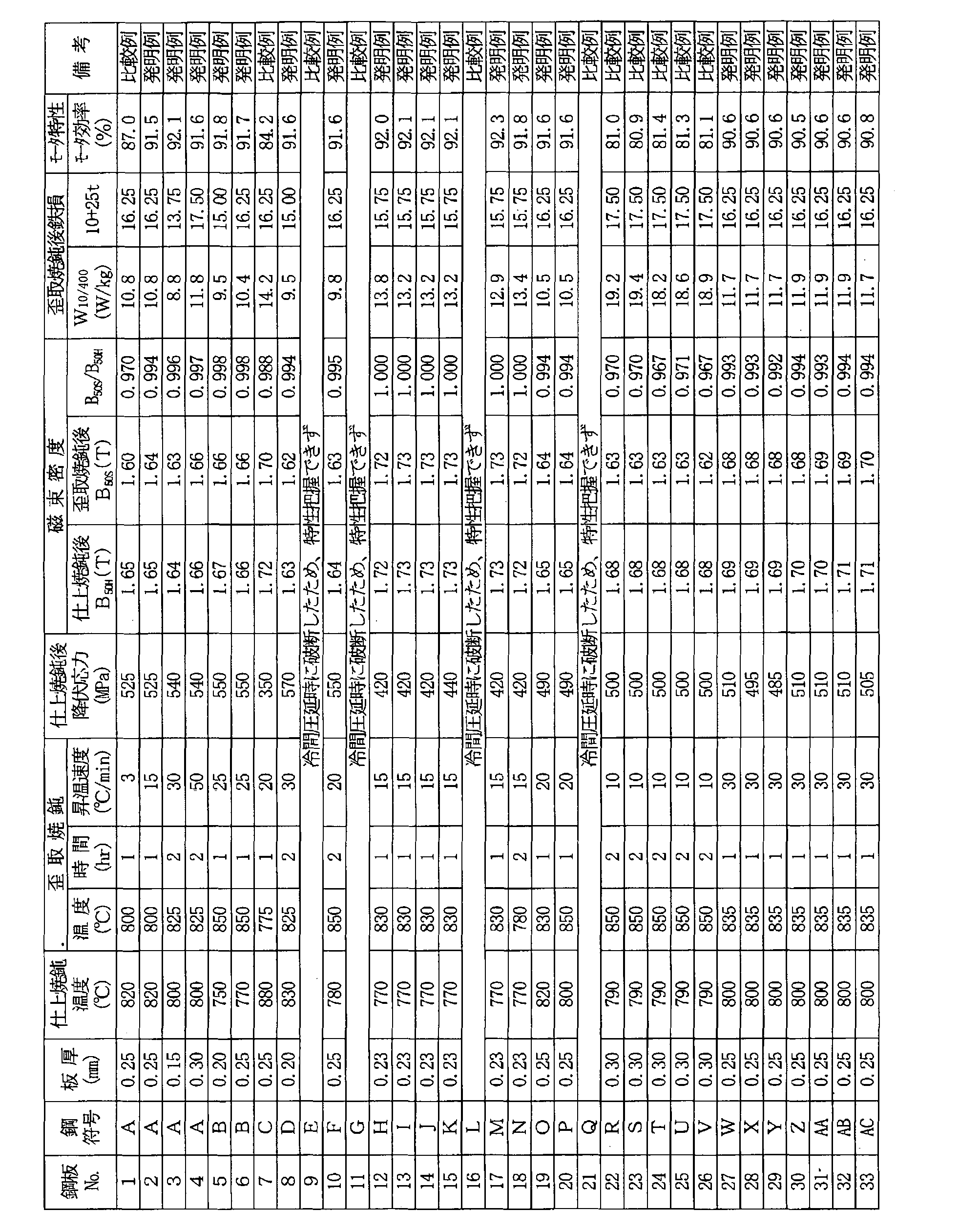
上記測定結果を、表2中に併記した。この結果から、本発明の鋼板から製造したモータは、モータ効率が安定して高いことが判る。 A pair of rotor cores and stator cores are prepared from each of the non-oriented electrical steel sheets after the finish annealing, and the assembled stator cores are heated to 600 ° C. to 850 ° C. at 10 ° C./min in an N 2 atmosphere. The temperature was raised and subjected to strain relief annealing that was held at 850 ° C. for 1 hr, and then assembled into one IPM motor, and the motor efficiency was measured. Note that the IPM motor used for the above measurement has a stator outer diameter of 150 mm, a stack thickness of 25 mm, and a motor output of 300 W. Measurement conditions were driven at 1500 rpm and 2 Nm, and the motor efficiency at the same output was measured.
The measurement results are also shown in Table 2. From this result, it can be seen that the motor manufactured from the steel plate of the present invention has a stable and high motor efficiency.
Claims (11)
- C:0.0050mass%以下、Si:2~7mass%、Mn:0.05~2.0mass%、P:0.2mass%以下、S:0.005mass%以下、Al:3mass%以下、N:0.005mass%以下、Ti:0.003mass%以下、Nb:0.005mass%以下およびV:0.005mass%以下を含有し、残部がFeおよび不可避的不純物からなる成分組成を有する鋼スラブを熱間圧延し、冷間圧延し、仕上焼鈍し、歪取焼鈍する無方向性電磁鋼板の製造方法において、
上記仕上焼鈍後の鋼板の降伏応力が400MPa以上、上記仕上焼鈍後の鋼板の磁束密度B50Hに対する上記仕上焼鈍後の鋼板に歪取焼鈍を施した後の磁束密度B50Sの比(B50S/B50H)が0.99以上となるように仕上焼鈍および歪取焼鈍の条件を調整することを特徴とする無方向性電磁鋼板の製造方法。 C: 0.0050 mass% or less, Si: 2 to 7 mass%, Mn: 0.05 to 2.0 mass%, P: 0.2 mass% or less, S: 0.005 mass% or less, Al: 3 mass% or less, N: A steel slab containing 0.005 mass% or less, Ti: 0.003 mass% or less, Nb: 0.005 mass% or less and V: 0.005 mass% or less, with the balance being composed of Fe and unavoidable impurities is heated. In the manufacturing method of the non-oriented electrical steel sheet that is cold rolled, cold rolled, finish annealed, and strain relief annealed,
The yield stress of finishing the steel sheet after annealing is higher 400 MPa, the finishing ratio of magnetic flux density B 50S after subjected to stress relief annealing the steel sheet after the final annealing for the magnetic flux density B 50H of the steel sheet after annealing (B 50S / A method for producing a non-oriented electrical steel sheet, characterized by adjusting the conditions of finish annealing and strain relief annealing so that B 50H ) is 0.99 or more. - 上記鋼スラブは、上記成分組成に加えてさらに、下記A~C群のうちの少なくとも1群の成分を含有することを特徴とする請求項1に記載の無方向性電磁鋼板の製造方法。
記
A群;Sn:0.005~0.20mass%およびSb:0.005~0.20mass%から選ばれる1種または2種
B群;Ca:0.001~0.010mass%、Mg:0.001~0.010mass%およびREM:0.001~0.010mass%のうちから選ばれる1種または2種以上
C群:Cr:0.01~0.5mass%およびCu:0.01~0.2mass%のうちから選ばれる1種または2種 The method for producing a non-oriented electrical steel sheet according to claim 1, wherein the steel slab further contains at least one component of the following groups A to C in addition to the component composition.
Group A; one or two selected from Sn: 0.005 to 0.20 mass% and Sb: 0.005 to 0.20 mass% Group B; Ca: 0.001 to 0.010 mass%, Mg: 0 One or more selected from 0.001 to 0.010 mass% and REM: 0.001 to 0.010 mass% Group C: Cr: 0.01 to 0.5 mass% and Cu: 0.01 to 0 1 type or 2 types selected from 2 mass% - 上記歪取焼鈍の条件を、歪取焼鈍後の鉄損W10/400(W/kg)が、板厚t(mm)との関係で、下記(1)式を満たすよう調整することを特徴とする請求項1または2に記載の無方向性電磁鋼板の製造方法。
W10/400≦10+25t ・・・(1) The condition of the stress relief annealing is adjusted so that the iron loss W 10/400 (W / kg) after the stress relief annealing satisfies the following formula (1) in relation to the plate thickness t (mm). The manufacturing method of the non-oriented electrical steel sheet according to claim 1 or 2.
W 10/400 ≦ 10 + 25t (1) - 上記歪取焼鈍の条件を、均熱温度を750~950℃、均熱時間を0.1~10hr、600℃から上記均熱温度までの昇温速度を8℃/min以上とすることを特徴とする請求項1~3のいずれかに記載の無方向性電磁鋼板の製造方法。 The conditions for the strain relief annealing are: a soaking temperature of 750 to 950 ° C., a soaking time of 0.1 to 10 hours, and a rate of temperature rise from 600 ° C. to the soaking temperature of 8 ° C./min or more. The method for producing a non-oriented electrical steel sheet according to any one of claims 1 to 3.
- ロータコア材とステータコア材が同一素材から採取するモータコアの製造方法であり、C:0.0050mass%以下、Si:2~7mass%、Mn:0.05~2.0mass%、P:0.2mass%以下、S:0.005mass%以下、Al:3mass%以下、N:0.005mass%以下、Ti:0.003mass%以下、Nb:0.005mass%以下およびV:0.005mass%以下を含有し、残部がFeおよび不可避的不純物からなり、降伏応力が400MPa以上である無方向性電磁鋼板をロータコアとし、かつ上記無方向性電磁鋼板に歪取焼鈍を施してステータコアとし、上記ロータコアの磁束密度B50Hに対する上記ステータコアの磁束密度B50Sの比(B50S/B50H)が0.99以上とすることを特徴とするモータコアの製造方法。 This is a motor core manufacturing method in which the rotor core material and the stator core material are collected from the same material, C: 0.0050 mass% or less, Si: 2-7 mass%, Mn: 0.05-2.0 mass%, P: 0.2 mass% Hereinafter, S: 0.005 mass% or less, Al: 3 mass% or less, N: 0.005 mass% or less, Ti: 0.003 mass% or less, Nb: 0.005 mass% or less, and V: 0.005 mass% or less In addition, a non-oriented electrical steel sheet having a balance of Fe and inevitable impurities and having a yield stress of 400 MPa or more is used as a rotor core, and the non-oriented electrical steel sheet is subjected to strain relief annealing to form a stator core. The magnetic flux density B of the rotor core the ratio of the magnetic flux density B 50S of the stator core for 50H (B 50S / B 50H) of 0.99 or less Motor core manufacturing method which is characterized in that a.
- 上記無方向性電磁鋼板は、上記成分組成に加えてさらに、下記A~C群のうちの少なくとも1群の成分を含有することを特徴とする請求項5に記載のモータコアの製造方法。
記
A群;Sn:0.005~0.20mass%およびSb:0.005~0.20mass%から選ばれる1種または2種
B群;Ca:0.001~0.010mass%、Mg:0.001~0.010mass%およびREM:0.001~0.010mass%のうちから選ばれる1種または2種以上
C群:Cr:0.01~0.5mass%およびCu:0.01~0.2mass%のうちから選ばれる1種または2種 6. The method for manufacturing a motor core according to claim 5, wherein the non-oriented electrical steel sheet further contains at least one component of the following groups A to C in addition to the component composition.
Group A; one or two selected from Sn: 0.005 to 0.20 mass% and Sb: 0.005 to 0.20 mass% Group B; Ca: 0.001 to 0.010 mass%, Mg: 0 One or more selected from 0.001 to 0.010 mass% and REM: 0.001 to 0.010 mass% Group C: Cr: 0.01 to 0.5 mass% and Cu: 0.01 to 0 1 type or 2 types selected from 2 mass% - 上記歪取焼鈍の条件を、歪取焼鈍後の鉄損W10/400(W/kg)が、板厚t(mm)との関係で、下記(1)式を満たすよう調整することを特徴とする請求項5または6に記載のモータコアの製造方法。
W10/400≦10+25t ・・・(1) The condition of the stress relief annealing is adjusted so that the iron loss W 10/400 (W / kg) after the stress relief annealing satisfies the following formula (1) in relation to the plate thickness t (mm). A method for manufacturing a motor core according to claim 5 or 6.
W 10/400 ≦ 10 + 25t (1) - 上記歪取焼鈍の条件を、均熱温度を750~950℃、均熱時間を0.1~10hr、600℃から上記均熱温度までの昇温速度を8℃/min以上とすることを特徴とする請求項5~7のいずれかに記載のモータコアの製造方法。 The conditions for the strain relief annealing are: a soaking temperature of 750 to 950 ° C., a soaking time of 0.1 to 10 hours, and a rate of temperature rise from 600 ° C. to the soaking temperature of 8 ° C./min or more. The method for producing a motor core according to any one of claims 5 to 7.
- ロータコア材とステータコア材が同一の無方向性電磁鋼板からなるモータコアであり、C:0.0050mass%以下、Si:2~7mass%、Mn:0.05~2.0mass%、P:0.2mass%以下、S:0.005mass%以下、Al:3mass%以下、N:0.005mass%以下、Ti:0.003mass%以下、Nb:0.005mass%以下およびV:0.005mass%以下を含有し、残部がFeおよび不可避的不純物からなり、ロータコア材の降伏応力が400MPa以上であり、かつ上記ロータコアの磁束密度B50Hに対する上記ステータコアの磁束密度B50Sの比(B50S/B50H)が0.99以上であることを特徴とするモータコア。 The rotor core material and the stator core material are motor cores made of the same non-oriented electrical steel sheet. C: 0.0050 mass% or less, Si: 2 to 7 mass%, Mn: 0.05 to 2.0 mass%, P: 0.2 mass % Or less, S: 0.005 mass% or less, Al: 3 mass% or less, N: 0.005 mass% or less, Ti: 0.003 mass% or less, Nb: 0.005 mass% or less, and V: 0.005 mass% or less and, the balance being Fe and unavoidable impurities, the yield stress of the rotor core material is not less than 400 MPa, and the ratio of the magnetic flux density B 50S of the stator core with respect to the magnetic flux density B 50H of the rotor core (B 50S / B 50H) is 0 A motor core characterized by being 99 or more.
- 上記無方向性電磁鋼板は、上記成分組成に加えてさらに、下記A~C群のうちの少なくとも1群の成分を含有することを特徴とする請求項9に記載のモータコア。
記
A群;Sn:0.005~0.20mass%およびSb:0.005~0.20mass%から選ばれる1種または2種
B群;Ca:0.001~0.010mass%、Mg:0.001~0.010mass%およびREM:0.001~0.010mass%のうちから選ばれる1種または2種以上
C群:Cr:0.01~0.5mass%およびCu:0.01~0.2mass%のうちから選ばれる1種または2種 The motor core according to claim 9, wherein the non-oriented electrical steel sheet further contains at least one component of the following groups A to C in addition to the component composition.
Group A; one or two selected from Sn: 0.005 to 0.20 mass% and Sb: 0.005 to 0.20 mass% Group B; Ca: 0.001 to 0.010 mass%, Mg: 0 One or more selected from 0.001 to 0.010 mass% and REM: 0.001 to 0.010 mass% Group C: Cr: 0.01 to 0.5 mass% and Cu: 0.01 to 0 1 type or 2 types selected from 2 mass% - 上記ステータコア材の鉄損W10/400(W/kg)が、板厚t(mm)との関係で、下記(1)式を満たすことを特徴とする請求項9または10に記載のモータコア。
W10/400≦10+25t ・・・(1)
11. The motor core according to claim 9, wherein iron loss W 10/400 (W / kg) of the stator core material satisfies the following expression (1) in relation to a plate thickness t (mm).
W 10/400 ≦ 10 + 25t (1)
Priority Applications (9)
| Application Number | Priority Date | Filing Date | Title |
|---|---|---|---|
| CN201880010448.8A CN110249063A (en) | 2017-02-07 | 2018-01-19 | The manufacturing method of non orientation electromagnetic steel plate and the manufacturing method of motor iron core and motor iron core |
| BR112019014799-3A BR112019014799B1 (en) | 2017-02-07 | 2018-01-19 | METHOD FOR PRODUCING NON-ORIENTED ELECTRIC STEEL SHEET, METHOD FOR PRODUCING MOTOR CORE AND MOTOR CORE |
| US16/483,965 US11104973B2 (en) | 2017-02-07 | 2018-01-19 | Method for producing non-oriented electrical steel sheet, method for producing motor core, and motor core |
| CA3051823A CA3051823C (en) | 2017-02-07 | 2018-01-19 | Method for producing non-oriented electrical steel sheet, method for producing motor core, and motor core |
| EP21204996.9A EP3974547A1 (en) | 2017-02-07 | 2018-01-19 | Motor core |
| JP2018518664A JP6601646B2 (en) | 2017-02-07 | 2018-01-19 | Non-oriented electrical steel sheet manufacturing method, motor core manufacturing method, and motor core |
| KR1020197023155A KR102295445B1 (en) | 2017-02-07 | 2018-01-19 | Method for producing non-oriented electrical steel sheet, method for producing motor core, and motor core |
| MX2019009357A MX2019009357A (en) | 2017-02-07 | 2018-01-19 | Method for producing non-oriented electromagnetic steel sheet, method for producing motor core, and motor core. |
| EP18750858.5A EP3581665B1 (en) | 2017-02-07 | 2018-01-19 | Method for producing non-oriented electrical steel sheet, method for producing motor core, and motor core |
Applications Claiming Priority (2)
| Application Number | Priority Date | Filing Date | Title |
|---|---|---|---|
| JP2017-019994 | 2017-02-07 | ||
| JP2017019994 | 2017-02-07 |
Publications (1)
| Publication Number | Publication Date |
|---|---|
| WO2018147044A1 true WO2018147044A1 (en) | 2018-08-16 |
Family
ID=63107326
Family Applications (1)
| Application Number | Title | Priority Date | Filing Date |
|---|---|---|---|
| PCT/JP2018/001533 WO2018147044A1 (en) | 2017-02-07 | 2018-01-19 | Method for producing non-oriented electromagnetic steel sheet, method for producing motor core, and motor core |
Country Status (10)
| Country | Link |
|---|---|
| US (1) | US11104973B2 (en) |
| EP (2) | EP3581665B1 (en) |
| JP (1) | JP6601646B2 (en) |
| KR (1) | KR102295445B1 (en) |
| CN (1) | CN110249063A (en) |
| BR (1) | BR112019014799B1 (en) |
| CA (1) | CA3051823C (en) |
| MX (1) | MX2019009357A (en) |
| TW (1) | TWI674322B (en) |
| WO (1) | WO2018147044A1 (en) |
Cited By (9)
| Publication number | Priority date | Publication date | Assignee | Title |
|---|---|---|---|---|
| KR20200035754A (en) * | 2018-09-27 | 2020-04-06 | 주식회사 포스코 | Non-oriented electrical steel sheet and method for manufacturing the same |
| WO2020091039A1 (en) * | 2018-11-02 | 2020-05-07 | 日本製鉄株式会社 | Non-oriented electromagnetic steel sheet |
| KR20200076832A (en) * | 2018-12-19 | 2020-06-30 | 주식회사 포스코 | Non-oriented electrical steel sheet and method for manufacturing the same |
| WO2020262063A1 (en) * | 2019-06-28 | 2020-12-30 | Jfeスチール株式会社 | Method for producing non-oriented electromagnetic steel sheet, method for producing motor core, and motor core |
| US20210079493A1 (en) * | 2018-02-02 | 2021-03-18 | Thyssenkrupp Steel Europe Ag | Electrical steel strip that can be but doesn't have to be reannealed |
| EP3904551A4 (en) * | 2018-12-27 | 2022-04-06 | JFE Steel Corporation | Non-oriented electrical steel sheet and method for producing same |
| EP3998358A4 (en) * | 2019-07-11 | 2022-07-13 | JFE Steel Corporation | Non-oriented electromagnetic steel sheet, method for producing same and motor core |
| EP4036257A4 (en) * | 2019-12-09 | 2023-06-07 | JFE Steel Corporation | Non-oriented electromagnetic steel sheet, motor core, and methods respectively for manufacturing same |
| US11962184B2 (en) | 2019-06-28 | 2024-04-16 | Jfe Steel Corporation | Method for producing non-oriented electrical steel sheet, method for producing motor core, and motor core |
Families Citing this family (7)
| Publication number | Priority date | Publication date | Assignee | Title |
|---|---|---|---|---|
| JP6738047B2 (en) * | 2017-05-31 | 2020-08-12 | Jfeスチール株式会社 | Non-oriented electrical steel sheet and its manufacturing method |
| DE102018201618A1 (en) | 2018-02-02 | 2019-08-08 | Thyssenkrupp Ag | Afterglow, but not nachglühpflichtiges electrical tape |
| MX2021004977A (en) * | 2018-10-31 | 2021-06-15 | Jfe Steel Corp | Method for manufacturing non-oriented electromagnetic steel sheet. |
| WO2021065555A1 (en) * | 2019-10-03 | 2021-04-08 | Jfeスチール株式会社 | Non-oriented electromagnetic steel sheet and method for manufacturing same |
| US20220393520A1 (en) * | 2019-12-16 | 2022-12-08 | Jfe Steel Corporation | Motor core and method of manufacturing the same |
| CN116888295B (en) * | 2021-03-31 | 2024-03-19 | 日本制铁株式会社 | Non-oriented electromagnetic steel sheet, motor core, method for manufacturing non-oriented electromagnetic steel sheet, and method for manufacturing motor core |
| US20230353023A1 (en) * | 2021-03-31 | 2023-11-02 | Nippon Steel Corporation | Rotating electrical machine, stator core and rotor core set, method for manufacturing rotating electrical machine, method for manufacturing non-oriented electrical steel sheet, method for manufacturing rotor and stator of rotating electrical machine, and non-oriented electrical steel sheet set |
Citations (8)
| Publication number | Priority date | Publication date | Assignee | Title |
|---|---|---|---|---|
| JP2006131963A (en) * | 2004-11-08 | 2006-05-25 | Nippon Steel Corp | High-grade non-oriented electromagnetic steel sheet having stable magnetic property, and manufacturing method therefor |
| JP2006213975A (en) * | 2005-02-04 | 2006-08-17 | Nippon Steel Corp | Non-oriented electromagnetic steel plate having excellent magnetic property, method for producing the same, and method for stress relieving annealing |
| JP2008050686A (en) | 2006-07-27 | 2008-03-06 | Nippon Steel Corp | Nonoriented silicon steel sheet having excellent strength and magnetic property and its production method |
| US20110273054A1 (en) * | 2010-05-04 | 2011-11-10 | Gwynne Johnston | Electrical steel, a motor, and a method for manufacture of electrical steel with high strength and low electrical losses |
| CN103667879A (en) * | 2013-11-27 | 2014-03-26 | 武汉钢铁(集团)公司 | Non-oriented electrical sheet with superior magnetic and mechanical properties, and production method of non-oriented electrical sheet |
| WO2016017263A1 (en) * | 2014-07-31 | 2016-02-04 | Jfeスチール株式会社 | Non-oriented electromagnetic steel plate and production method therefor, and motor core and production method therefor |
| JP2016138316A (en) * | 2015-01-28 | 2016-08-04 | Jfeスチール株式会社 | Nonoriented magnetic steel sheet |
| JP2016151050A (en) * | 2015-02-18 | 2016-08-22 | Jfeスチール株式会社 | Non-oriented silicon steel sheet, method for producing the same and motor core |
Family Cites Families (6)
| Publication number | Priority date | Publication date | Assignee | Title |
|---|---|---|---|---|
| JPH0819466B2 (en) * | 1990-02-01 | 1996-02-28 | 日本鋼管株式会社 | Non-oriented electrical steel sheet manufacturing method |
| WO2001098550A1 (en) | 2000-06-19 | 2001-12-27 | Nkk Corporation | Non-oriented electromagnetic steel sheet and method for production thereof |
| KR100956530B1 (en) * | 2001-06-28 | 2010-05-07 | 제이에프이 스틸 가부시키가이샤 | Nonoriented electromagnetic steel sheet |
| JP5995002B2 (en) | 2013-08-20 | 2016-09-21 | Jfeスチール株式会社 | High magnetic flux density non-oriented electrical steel sheet and motor |
| JP6319574B2 (en) | 2014-08-14 | 2018-05-09 | Jfeスチール株式会社 | Non-oriented electrical steel sheet with excellent magnetic properties |
| JP6027636B2 (en) * | 2015-01-22 | 2016-11-16 | 株式会社日本トリム | Electrolyzed water generator |
-
2018
- 2018-01-19 CA CA3051823A patent/CA3051823C/en active Active
- 2018-01-19 JP JP2018518664A patent/JP6601646B2/en active Active
- 2018-01-19 US US16/483,965 patent/US11104973B2/en active Active
- 2018-01-19 MX MX2019009357A patent/MX2019009357A/en unknown
- 2018-01-19 KR KR1020197023155A patent/KR102295445B1/en active IP Right Grant
- 2018-01-19 CN CN201880010448.8A patent/CN110249063A/en active Pending
- 2018-01-19 EP EP18750858.5A patent/EP3581665B1/en active Active
- 2018-01-19 BR BR112019014799-3A patent/BR112019014799B1/en active IP Right Grant
- 2018-01-19 WO PCT/JP2018/001533 patent/WO2018147044A1/en unknown
- 2018-01-19 EP EP21204996.9A patent/EP3974547A1/en not_active Withdrawn
- 2018-01-29 TW TW107103105A patent/TWI674322B/en active
Patent Citations (8)
| Publication number | Priority date | Publication date | Assignee | Title |
|---|---|---|---|---|
| JP2006131963A (en) * | 2004-11-08 | 2006-05-25 | Nippon Steel Corp | High-grade non-oriented electromagnetic steel sheet having stable magnetic property, and manufacturing method therefor |
| JP2006213975A (en) * | 2005-02-04 | 2006-08-17 | Nippon Steel Corp | Non-oriented electromagnetic steel plate having excellent magnetic property, method for producing the same, and method for stress relieving annealing |
| JP2008050686A (en) | 2006-07-27 | 2008-03-06 | Nippon Steel Corp | Nonoriented silicon steel sheet having excellent strength and magnetic property and its production method |
| US20110273054A1 (en) * | 2010-05-04 | 2011-11-10 | Gwynne Johnston | Electrical steel, a motor, and a method for manufacture of electrical steel with high strength and low electrical losses |
| CN103667879A (en) * | 2013-11-27 | 2014-03-26 | 武汉钢铁(集团)公司 | Non-oriented electrical sheet with superior magnetic and mechanical properties, and production method of non-oriented electrical sheet |
| WO2016017263A1 (en) * | 2014-07-31 | 2016-02-04 | Jfeスチール株式会社 | Non-oriented electromagnetic steel plate and production method therefor, and motor core and production method therefor |
| JP2016138316A (en) * | 2015-01-28 | 2016-08-04 | Jfeスチール株式会社 | Nonoriented magnetic steel sheet |
| JP2016151050A (en) * | 2015-02-18 | 2016-08-22 | Jfeスチール株式会社 | Non-oriented silicon steel sheet, method for producing the same and motor core |
Non-Patent Citations (1)
| Title |
|---|
| See also references of EP3581665A4 |
Cited By (21)
| Publication number | Priority date | Publication date | Assignee | Title |
|---|---|---|---|---|
| US11788168B2 (en) * | 2018-02-02 | 2023-10-17 | Thyssenkrupp Steel Europe Ag | Electrical steel strip that can be but doesn't have to be reannealed |
| US20210079493A1 (en) * | 2018-02-02 | 2021-03-18 | Thyssenkrupp Steel Europe Ag | Electrical steel strip that can be but doesn't have to be reannealed |
| CN113195769A (en) * | 2018-09-27 | 2021-07-30 | Posco公司 | Non-oriented electrical steel sheet and method for manufacturing the same |
| KR102120276B1 (en) * | 2018-09-27 | 2020-06-08 | 주식회사 포스코 | Non-oriented electrical steel sheet and method for manufacturing the same |
| KR20200035754A (en) * | 2018-09-27 | 2020-04-06 | 주식회사 포스코 | Non-oriented electrical steel sheet and method for manufacturing the same |
| EP3859039A4 (en) * | 2018-09-27 | 2021-08-04 | Posco | Non-grain oriented electrical steel and method for manufacturing same |
| JPWO2020091039A1 (en) * | 2018-11-02 | 2021-09-02 | 日本製鉄株式会社 | Non-oriented electrical steel sheet |
| JP7143900B2 (en) | 2018-11-02 | 2022-09-29 | 日本製鉄株式会社 | Non-oriented electrical steel sheet |
| CN112654723A (en) * | 2018-11-02 | 2021-04-13 | 日本制铁株式会社 | Non-oriented electromagnetic steel sheet |
| WO2020091039A1 (en) * | 2018-11-02 | 2020-05-07 | 日本製鉄株式会社 | Non-oriented electromagnetic steel sheet |
| CN112654723B (en) * | 2018-11-02 | 2023-04-04 | 日本制铁株式会社 | Non-oriented electromagnetic steel sheet |
| KR20200076832A (en) * | 2018-12-19 | 2020-06-30 | 주식회사 포스코 | Non-oriented electrical steel sheet and method for manufacturing the same |
| KR102241468B1 (en) | 2018-12-19 | 2021-04-16 | 주식회사 포스코 | Non-oriented electrical steel sheet and method for manufacturing the same |
| EP3904551A4 (en) * | 2018-12-27 | 2022-04-06 | JFE Steel Corporation | Non-oriented electrical steel sheet and method for producing same |
| CN114008224A (en) * | 2019-06-28 | 2022-02-01 | 杰富意钢铁株式会社 | Method for manufacturing non-oriented electromagnetic steel sheet, method for manufacturing motor core, and motor core |
| JP7054074B2 (en) | 2019-06-28 | 2022-04-13 | Jfeスチール株式会社 | Manufacturing method of non-oriented electrical steel sheet, manufacturing method of motor core and motor core |
| JPWO2020262063A1 (en) * | 2019-06-28 | 2021-09-13 | Jfeスチール株式会社 | Manufacturing method of non-oriented electrical steel sheet, manufacturing method of motor core and motor core |
| WO2020262063A1 (en) * | 2019-06-28 | 2020-12-30 | Jfeスチール株式会社 | Method for producing non-oriented electromagnetic steel sheet, method for producing motor core, and motor core |
| US11962184B2 (en) | 2019-06-28 | 2024-04-16 | Jfe Steel Corporation | Method for producing non-oriented electrical steel sheet, method for producing motor core, and motor core |
| EP3998358A4 (en) * | 2019-07-11 | 2022-07-13 | JFE Steel Corporation | Non-oriented electromagnetic steel sheet, method for producing same and motor core |
| EP4036257A4 (en) * | 2019-12-09 | 2023-06-07 | JFE Steel Corporation | Non-oriented electromagnetic steel sheet, motor core, and methods respectively for manufacturing same |
Also Published As
| Publication number | Publication date |
|---|---|
| US11104973B2 (en) | 2021-08-31 |
| EP3974547A1 (en) | 2022-03-30 |
| TWI674322B (en) | 2019-10-11 |
| EP3581665B1 (en) | 2021-12-22 |
| JP6601646B2 (en) | 2019-11-06 |
| MX2019009357A (en) | 2019-09-19 |
| BR112019014799B1 (en) | 2023-10-24 |
| EP3581665A1 (en) | 2019-12-18 |
| CA3051823C (en) | 2022-07-12 |
| TW201835338A (en) | 2018-10-01 |
| CN110249063A (en) | 2019-09-17 |
| EP3581665A4 (en) | 2020-04-15 |
| CA3051823A1 (en) | 2018-08-16 |
| KR102295445B1 (en) | 2021-08-27 |
| US20200010918A1 (en) | 2020-01-09 |
| BR112019014799A2 (en) | 2020-02-27 |
| KR20190104580A (en) | 2019-09-10 |
| JPWO2018147044A1 (en) | 2019-02-14 |
Similar Documents
| Publication | Publication Date | Title |
|---|---|---|
| JP6601646B2 (en) | Non-oriented electrical steel sheet manufacturing method, motor core manufacturing method, and motor core | |
| TWI672384B (en) | Method for manufacturing non-oriented electrical steel sheet, method for manufacturing motor core, and motor core | |
| JP6866935B2 (en) | Manufacturing method of non-oriented electrical steel sheet | |
| JP6269971B2 (en) | Non-oriented electrical steel sheet and motor core | |
| JP5273235B2 (en) | Method for producing non-oriented electrical steel sheet | |
| WO2020262063A1 (en) | Method for producing non-oriented electromagnetic steel sheet, method for producing motor core, and motor core | |
| US11962184B2 (en) | Method for producing non-oriented electrical steel sheet, method for producing motor core, and motor core | |
| WO2024057940A1 (en) | High-strength non-oriented electromagnetic steel plate and method for manufacturing same | |
| JP2005120431A (en) | Method for manufacturing high-strength nonoriented silicon steel sheet having excellent magnetic characteristic |
Legal Events
| Date | Code | Title | Description |
|---|---|---|---|
| ENP | Entry into the national phase |
Ref document number: 2018518664 Country of ref document: JP Kind code of ref document: A |
|
| 121 | Ep: the epo has been informed by wipo that ep was designated in this application |
Ref document number: 18750858 Country of ref document: EP Kind code of ref document: A1 |
|
| ENP | Entry into the national phase |
Ref document number: 3051823 Country of ref document: CA |
|
| REG | Reference to national code |
Ref country code: BR Ref legal event code: B01A Ref document number: 112019014799 Country of ref document: BR |
|
| ENP | Entry into the national phase |
Ref document number: 20197023155 Country of ref document: KR Kind code of ref document: A |
|
| NENP | Non-entry into the national phase |
Ref country code: DE |
|
| ENP | Entry into the national phase |
Ref document number: 2018750858 Country of ref document: EP Effective date: 20190909 |
|
| ENP | Entry into the national phase |
Ref document number: 112019014799 Country of ref document: BR Kind code of ref document: A2 Effective date: 20190718 |