EP4455079A1 - Ammoxidationsreaktor und verfahren zur herstellung von salpetersäure - Google Patents
Ammoxidationsreaktor und verfahren zur herstellung von salpetersäure Download PDFInfo
- Publication number
- EP4455079A1 EP4455079A1 EP22909960.1A EP22909960A EP4455079A1 EP 4455079 A1 EP4455079 A1 EP 4455079A1 EP 22909960 A EP22909960 A EP 22909960A EP 4455079 A1 EP4455079 A1 EP 4455079A1
- Authority
- EP
- European Patent Office
- Prior art keywords
- coil
- disposed
- ring
- oxidation reactor
- assembly
- Prior art date
- Legal status (The legal status is an assumption and is not a legal conclusion. Google has not performed a legal analysis and makes no representation as to the accuracy of the status listed.)
- Pending
Links
Images


Classifications
-
- C—CHEMISTRY; METALLURGY
- C01—INORGANIC CHEMISTRY
- C01B—NON-METALLIC ELEMENTS; COMPOUNDS THEREOF; METALLOIDS OR COMPOUNDS THEREOF NOT COVERED BY SUBCLASS C01C
- C01B21/00—Nitrogen; Compounds thereof
- C01B21/20—Nitrogen oxides; Oxyacids of nitrogen; Salts thereof
- C01B21/38—Nitric acid
-
- B—PERFORMING OPERATIONS; TRANSPORTING
- B01—PHYSICAL OR CHEMICAL PROCESSES OR APPARATUS IN GENERAL
- B01J—CHEMICAL OR PHYSICAL PROCESSES, e.g. CATALYSIS OR COLLOID CHEMISTRY; THEIR RELEVANT APPARATUS
- B01J12/00—Chemical processes in general for reacting gaseous media with gaseous media; Apparatus specially adapted therefor
- B01J12/007—Chemical processes in general for reacting gaseous media with gaseous media; Apparatus specially adapted therefor in the presence of catalytically active bodies, e.g. porous plates
-
- B—PERFORMING OPERATIONS; TRANSPORTING
- B01—PHYSICAL OR CHEMICAL PROCESSES OR APPARATUS IN GENERAL
- B01J—CHEMICAL OR PHYSICAL PROCESSES, e.g. CATALYSIS OR COLLOID CHEMISTRY; THEIR RELEVANT APPARATUS
- B01J19/00—Chemical, physical or physico-chemical processes in general; Their relevant apparatus
- B01J19/32—Packing elements in the form of grids or built-up elements for forming a unit or module inside the apparatus for mass or heat transfer
-
- C—CHEMISTRY; METALLURGY
- C01—INORGANIC CHEMISTRY
- C01B—NON-METALLIC ELEMENTS; COMPOUNDS THEREOF; METALLOIDS OR COMPOUNDS THEREOF NOT COVERED BY SUBCLASS C01C
- C01B21/00—Nitrogen; Compounds thereof
- C01B21/20—Nitrogen oxides; Oxyacids of nitrogen; Salts thereof
- C01B21/24—Nitric oxide (NO)
- C01B21/26—Preparation by catalytic or non-catalytic oxidation of ammonia
- C01B21/28—Apparatus
-
- B—PERFORMING OPERATIONS; TRANSPORTING
- B01—PHYSICAL OR CHEMICAL PROCESSES OR APPARATUS IN GENERAL
- B01J—CHEMICAL OR PHYSICAL PROCESSES, e.g. CATALYSIS OR COLLOID CHEMISTRY; THEIR RELEVANT APPARATUS
- B01J19/00—Chemical, physical or physico-chemical processes in general; Their relevant apparatus
- B01J19/32—Packing elements in the form of grids or built-up elements for forming a unit or module inside the apparatus for mass or heat transfer
- B01J19/325—Attachment devices therefor, e.g. hooks, consoles, brackets
-
- B—PERFORMING OPERATIONS; TRANSPORTING
- B01—PHYSICAL OR CHEMICAL PROCESSES OR APPARATUS IN GENERAL
- B01J—CHEMICAL OR PHYSICAL PROCESSES, e.g. CATALYSIS OR COLLOID CHEMISTRY; THEIR RELEVANT APPARATUS
- B01J2219/00—Chemical, physical or physico-chemical processes in general; Their relevant apparatus
- B01J2219/00049—Controlling or regulating processes
- B01J2219/00051—Controlling the temperature
- B01J2219/00074—Controlling the temperature by indirect heating or cooling employing heat exchange fluids
- B01J2219/00076—Controlling the temperature by indirect heating or cooling employing heat exchange fluids with heat exchange elements inside the reactor
- B01J2219/00083—Coils
-
- B—PERFORMING OPERATIONS; TRANSPORTING
- B01—PHYSICAL OR CHEMICAL PROCESSES OR APPARATUS IN GENERAL
- B01J—CHEMICAL OR PHYSICAL PROCESSES, e.g. CATALYSIS OR COLLOID CHEMISTRY; THEIR RELEVANT APPARATUS
- B01J2219/00—Chemical, physical or physico-chemical processes in general; Their relevant apparatus
- B01J2219/00049—Controlling or regulating processes
- B01J2219/00051—Controlling the temperature
- B01J2219/00159—Controlling the temperature controlling multiple zones along the direction of flow, e.g. pre-heating and after-cooling
Definitions
- the application relates to the technical field of nitric acid producing equipment, and in particular relates to an ammonia oxidation reactor and method for producing nitric acid.
- Ammonia oxidation reactor is the equipment that ammonia and oxygen produce nitrogen oxides via catalytic reaction. According to the different production pressures, the produce of nitric acid in ammonia oxidation reactors can be classified as atmospheric pressure, medium pressure, high pressure and double pressurisation.
- the production of nitric acid basically involves: the first step of oxidising gaseous ammonia with air over a suitable catalyst to obtain a gaseous product containing oxides of nitrogen; and the second step of contacting the gaseous product with water in order to absorb the above mentioned oxides and obtain HNO 3 .
- the first step of ammonia oxidation is usually carried out under pressure in a suitable vessel (further known as a burner or combustion reactor).
- the catalyst is typically a platinum wire mesh which is supported by baskets within the reactor or, if necessary, contains under the mesh a high temperature resistant packing support or a high temperature resistant catalyst for N 2 O reduction.
- the ammonia-air mixture enters the reactor from the top entrance, passes through the gas distributor, and is evenly distributed in the platinum network to generate a mixture of nitric oxide and water vapour, and release a large amount of heat.
- the equipment is covered with a layer of water-cooled walls in the inside wall; the existing distributor distribution is not uniform, resulting in bias flow leading to inadequate burning reaction, and likely to cause the platinum mesh and platinum mesh under the temperature of the uneven radial distribution of the affected nitrogen monoxide production yield.
- a heat recovery device is set up in the ammonia oxidation reactor, and a water-cooled wall module is set up in order to prevent damage to the equipment from excessively high temperatures;
- the coiled tube module for the heat recovery device consists of a multi-layer coiled tubes that are connected in the direction of head to tail and are arranged in a upright direction, and each layer of the coiled tubes is a seamless tube coiled at an equal spacing and each layer of the coiled tubes is coiled in the same way.
- each layer of the level of coiler can not maintain the original winding state resulting in the phenomenon of uneven heat transfer and the reduction of the heat transfer efficiency.
- the existing ammonia oxidation reactor for the producing of nitric acid presents high ammonia consumption, high platinum catalyst consumption, high energy consumption, low heat recycling rate, and short service life.
- the present application is intended to address, at least in part, one of the technical problems in the related technology.
- an ammonia oxidation reactor for producing nitric acid comprising:
- said heat recycling unit further comprises a water-cooled wall tube group; said water-cooled wall tube group is circumferentially disposed inside the furnace interior close to said shell; and said water-cooled wall tube group is disposed at an external circumferential periphery of said coil assembly.
- said coil assembly comprises a plurality of fixing assemblies, each said coil being provided with one said fixing assembly; said fixing assemblies comprising a plurality of tie-downs; the a plurality of said tie-downs each being provided radially circumferentially in the plane of said coil and wrapped around the exterior of said coil to tie down said coil.
- said fixing assembly comprises an position adjustment assembly, said position adjustment assembly comprising:
- said first locating member and said second locating member are both spaced apart within a space between said first coil ring and said second coil ring, and said first locating member and said second locating member are alternately disposed within the spacing formed by said first coil ring and said second coil ring.
- said coil assembly comprises a plurality of airflow dispersing members, each said coil being provided with one said airflow dispersing member above said coil; said airflow dispersing members correlating to said "S" shaped structure in the axial direction of said coil assembly, said airflow dispersing members shield said "S" shaped structure.
- said inlet centralise box is provided with at least two throttle hole joints; two of said throttle hole joints are connected to two of said coil assemblies.
- said inlet centralise box is provided with at least two throttle hole joints; two of said throttle hole joints are connected to two of said coil assemblies.
- a plurality of said water-cooled wall tubes are in the same plane with said furnace chamber at their highest point in the axial direction.
- said heat recycling unit comprises a shroud; said shroud is positioned on an outer circumferential edge of said coil assemblies, and said shroud is positioned between said coil assemblies and said water-cooled wall tube group.
- said combustion unit further comprises a support assemble for supporting the fixation of said platinum mesh layer; said support assemble comprising a support member, said support member disposed underneath said platinum mesh layer for supporting said platinum mesh layer.
- said support assemble further comprises a elastic compression member, said elastic compression member comprising a gasket, an inverted T-shaped support ring, a elastic snap ring, and a cylinder section; wherein said platinum mesh layer is provided with gaskets on each side above and below; wherein said inverted T-shaped support ring is set on the exterior of hollow circular said cylinder section; said elastic snap ring is set on top of said inverted T-shaped support ring; the central axis of said inverted T-shaped support ring, said elastic snap ring, and said hollow circular cylinder section are coincidental; and a pressure strip is set in said top cover, said pressure strip is connected in contact with said elastic snap ring.
- a elastic compression member comprising a gasket, an inverted T-shaped support ring, a elastic snap ring, and a cylinder section; wherein said platinum mesh layer is provided with gaskets on each side above and below; wherein said inverted T-shaped support ring is set on the exterior of hollow circular said cylinder section; said elastic snap
- said inverted T-shaped support ring comprises a support circle and a support ring; wherein said support circle is fixedly set on the exterior of the hollow circular of said cylinder section; said support ring is fixedly set above said support circle; and said elastic snap ring is set above said support ring.
- said support circle is fixed welded to outer side of said barrel section.
- the diameter of said support ring is smaller than the diameter of said support circle, and said support ring is vertically weld fixed in the middle of said support circle.
- said elastic snap ring is snapped onto said support ring, said elastic snap ring has a gap with said barrel knuckle, and the diameter of said elastic snap ring is in excess of the diameter of said support circle.
- said barrel knuckle is a high temperature resistant alloy.
- a platinum mesh compression ring is positioned between said gasket and said barrel knuckle.
- said support structure comprises at least a base, said base being located below an outer edge of said platinum mesh layer.
- said support structure further comprises a grid support frame, said grid support frame being disposed below said platinum mesh layer.
- said combustion unit further comprises a gas distributor; wherein said gas distributor is positioned inside said furnace chamber.
- said combustion unit further comprises a deflector cone; wherein said deflector cone is disposed on said top cover and inside said furnace chamber, and said gas distributor is positioned inside said deflector cone to evenly distribute a mixture of ammonia gas and air over said platinum mesh layer.
- said combustion unit further comprises an ignition assemble; wherein said ignition assemble comprises an igniter, an ignition distributor tube, and an ignition gas tube; wherein said igniter ignites an ignition gas passed through said ignition gas tube and ignites the entirety of said platinum mesh layer using said ignition distributor tube.
- said top cover is provided with at least one viewing window for observing combustion within said furnace chamber.
- said top cover is equipped with a protective air tube; for passing a protective gas into said furnace chamber to prevent high temperatures in the dead zone.
- nitric acid is proposed according to a second aspect of the present application, wherein an ammonia oxidation reactor such as in any of the embodiments set forth above is utilised for the production of nitric acid.
- the process method for producing nitric acid comprises the steps of;
- said post-reaction hot gas stream's temperature is 800-1000°C and the outlet temperature is 350-450°C after heat exchange with said coil assemblies.
- said furnace chamber inlet gas is an ammonia-air mixture comprising ammonia and air; wherein the ammonia-air mixture is at a temperature of 200-400°C, and wherein the molar volume ratio of ammonia to air is 8-12%, based on the ammonia-air mixture.
- this application provided the support assemble to elastic ally fix the platinum mesh layer, and the platinum mesh layer is pressured by using the gravity of the top cover itself, with the elastic compression device as the object of transmitting the force, and when the top cover is sealed, the compression strip welded on the cylinder in the inner and lower parts of the top cover is in contact with the elastic snap ring, and the elastic snap ring is downwardly pressed on the end far away from the cylinder section to form the elastic deformation, so that it achieves the sealing and at the same time presses the platinum mesh layer.
- the heat recycling unit in this application enables the high temperature gas to be uniformly distributed in sequence and to pass downwardly in order; the high temperature gas is carried out from the top to the bottom after heat exchange and discharged and enters the back process, the heat recycling unit in the embodiment of the application is able to recycle the heat energy and reduce the influence of high temperature on the safety and reliability of the ammonia oxidation reactor, so as to stabilise the process conditions for the production of nitric acid, and to achieve the purpose of the production of nitric acid.
- an ammonia oxidation reactor includes a shell, wherein the coil assemblies include at least two sets of coil assemblies, the two coil assemblies being positioned in an axial direction of the shell, wherein the axial direction of the coil assemblies coincides with the axial direction of the shell.
- the two coil assemblies are a coil assembly for an evaporation section and a coil assembly for a subthermal section.
- the coil assembly include a plurality of horizontal coils set side by side in the axial direction of the shell, wherein the horizontal coil are coiled for the coils to be coiled in the plane in accordance with an equally spiraling manner.
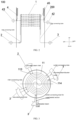
- the axial direction of the shell 200 in the embodiment of the application is same as the up and down direction, and the radial direction is same as the left and right direction, as shown in FIG. 1 .
- an ammonia oxidation reactor 1000 for the production of nitric acid comprises: a shell 200 and a top cover 400 capped above the shell 200 forming a furnace chamber 300, a combustion unit 500, and a heat recycling unit 100; wherein the furnace chamber 300 comprises a first space and a second space that are connected at upward and downward;
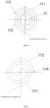
- the coiler tube 11 is coiled from the end of the first inlet guide tube 113 from the outside to the inside in an isometric helical manner in the first direction to form a plurality of first coiler rings 111 of different circle diameters, and the coiler tube 11 is curved into an "S" shape internally and then coiled from the inside to the outside in an isometric helical manner in the second direction to form a plurality of second coiler rings 112 of different circle diameters; wherein the second coiler ring 112 is positioned between two neighbouring first coiler rings 111; wherein the first direction is in the opposite direction to the second direction.
- the axial direction of the housing 200 in the embodiment of the application coincides with the axial direction of the coil assembly 1, specifically with the up and down direction, and the radial direction in the horizontal plane of the coils 11 coincides with the left and right direction, as shown in FIG. 2 .
- the heat recycling unit 100 is disposed inside the shell 200 of the ammonia oxidation reactor 1000, wherein the heat recycling unit 100 comprises at least two coil assemblies 1, the at least two coil assemblies 1 being disposed inside the shell 200 side-by-side in an upward and downward direction.
- the coil assembly 1 of the evaporation section and the coil assembly 1 of the subheat section both comprise a plurality of coils 11 disposed side by side in an upwardand downward direction, as shown in FIG. 2-FIG. 3 and FIG. 6-FIG. 7 .
- the first inlet guide tube 113 and the first outlet guide tube 114 are positioned at each end of the coil 11, i.e., the inlet end of the coil 11 is connected to the first inlet guide tube 113, and the inlet and outlet ends of the coil 11 are connected to the first outlet guide tube 114.
- the coil 11 is coiled from the inlet end from the outside to the inside in an equally spaced spiral manner in accordance with a first direction (clockwise or counterclockwise) to form a plurality of first coil rings 111 of different circle diameters; coil 11 in the internal bending into "S" shape and then in the second direction in an equally spaced spiral way from the inside to the outside coiled to form a plurality of different circle diameter of the second coil ring 112, the second coil ring 112 is located in the neighbouring two of the first coil ring 111 between the two, as shown in FIG. 6 .
- the first direction is clockwise coiling
- the second direction is counterclockwise coiling
- the first direction is counterclockwise coiling
- the second direction is clockwise coiling.
- the first coil ring 111 in the horizontal plane of the coiler 11, from the outside to the inside sequentially arranged and the spacing is the same, but the circle diameter from large to small; similarly the second coil ring 112 in the horizontal plane of the coiler 11, from the inside to the outside sequentially arranged and the spacing is the same, but the circle diameter are from small to large.
- the second coil ring 112 is positioned between two neighbouring first coil rings 111, at the same distance from the left and right neighbouring first coil rings 111.
- the first inlet guide tube 113 is positioned at the outermost ring of the first coil ring 111 and the first outlet guide tube 114 is positioned at the outermost ring of the second coil ring 112.
- the coiler 11 in the embodiments of this application in the actual production process can be in the same plane in accordance with the same pitch spiral coiled way, can also be assembled by a plurality of arcs or semi-circular line splicing. Understandably, the installation height of each layer of the coiler 11 is different, the temperature is also different, the heat absorbed is also different, for this reason, different layers of the coiler 11 spiral pitch can be different.
- the first outlet guide tube 114 of the upper coil 11 corresponds to the first inlet guide tube 113 of the lower coil 11 in the up and down direction, facilitating the assembly connection of the upper coil 11 to the lower coil 11.
- each layer of coils 11 is installed at a different height and is at a different temperature from the high temperature to which it is subjected.
- the coils 11 can be combined.
- each layer of the coils 11 in some of the coils 11 in the coil assembly 1 subjected to higher temperatures, each layer of the coils 11 is connected to the inlet centralise box 2 via an inlet connecting tube with a first inlet guide tube 113, and the first outlet guide tube 114 is connected to the outlet centralise box 3 via an outlet connecting tube to realise an inlet end and an outlet end of a layer of the coils 11; in some of the coils 11 subjected to lower temperatures in the coil assembly 1, two layers of coils 11 may be grouped together, and in some embodiments, Fig.
- Fig. 6 shows an upper layer of coils 11 and Fig. 7 shows a lower layer of coils
- the first inlet guide tube 113 of the upper layer of coils 11 is connected to the inlet centralise box 2 via the inlet connecting tube
- the first outlet guide tube 114 of the upper layer of coils 11 is connected to the first inlet guide tube 113 of the lower layer of coils 11
- the lower layer of coils 11 is connected to the outlet centralise box 3 via the outlet connecting tube.
- the first outlet guide tube 114 of the lower layer coil 11 is connected to the outlet centralise box 3 via the outlet connecting tube to enable the two-layer coil to have one inlet end and one outlet end, and similarly, when the coil assembly 1 are subjected to a very low temperature of some of the coils 11, the three-layer or even the multi-layer coils 11 are set up with reference to the above to have one inlet end and one outlet end.
- the above settings are exemplary but not restrictive description, the specific coiler 11 settings of the technical personnel in the field according to the actual needs of the flexible combination can be.
- the upper layer of coils 11 when the two layers of coils 11 as a group, the upper layer of coils 11 from the inlet end in a clockwise equally spaced spiral way from the outside to the inside of the coil to form a plurality of different circle diameter of the first coil ring 111; and the upper layer of coils 11 in the internal bending into the "S" shape, and then in a counterclockwise equally spaced spiral way from the inside to the outside of the coil to form a circle diameter of different second coil ring 112, the second coil ring 112 is located between the two neighbouring first coil ring 111.
- the first outlet guide tube 114 of the upper layer coiler 11 is in an upward and downward direction corresponding to the first inlet guide tube 113 of the lower layer coiler 11, which assembles and connects the upper layer coiler 11 with the lower layer coiler 11;
- the lower layer coiler 11 is coiled from the inlet end from the outside to the inside in the counterclockwise direction in an isometric helix to form a plurality of first coiler loops 111 of different ring diameters, and the lower layer coiler 11 is internally bent into an "S" shape and then in accordance with the clockwise direction in an equally spaced helical manner from the inside to the outside of the coil to form a plurality of second coil ring 112 with different ring diameters, the second coil ring 112 is located between two neighbouring first coil ring 111. That is, when the upper and lower coils 11 are to be connected, the lower coil 11 is coiled in the opposite direction to the upper coil 11.
- the inlet centralise box 2 is coupled with at least two throttle hole joints; wherein one of the throttle hole joints is connected to a coil assembly of the evaporation section; and wherein the other throttle hole joint is connected to a coil assembly 1 of the subthermal section.
- the two throttle hole joints are enabling to make a different amount of water within the coil assembly 1 of the evaporation section and the coil assembly 1 of the subthermal section.
- the coil assembly 1 comprise a plurality of fixing assemblies 12, one fixing assembly 12 being installed on each coil 11; the fixing assembly 12 comprise a plurality of tie-downs 121; a plurality of tie-downs 121 are each installed radially circumferentially within a horizontal plane of the coil 11 and wrapped around the exterior of the coil 11 to tie down the coil 11.
- the tie member 121 is interpreted as a flat steel strip, and the flat steel strip is radially annularly set in the plane of the coil 11 to wrap around the outside of the coil 11.
- the skilled person in the field may set up a plurality of flat steel strips according to the actual situation, such as setting up 4 flat steel strips, that is, the flat steel strips are spaced apart by 90°; the skilled person in the field may also set up 6 flat steel strips or 8 flat steel strips and so on.
- the fixing assembly 12 includes an position adjustment assembly 122
- the position adjustment assembly 122 includes a plurality of first position adjustment assemblies 1221 and a plurality of second position adjustment assemblies 1222: a plurality of the first position adjustment assemblies 1221 are evenly distributed in a circumferential plane of the coil 11 separately;
- the first position adjustment assembly 1221 comprises a plurality of first locating members 12211 radially distributed along the same orientation; the first locating member 12211 are snap-fitted in the space between the first coil ring 111 and the second coil ring 112;
- the first locating member 12211 comprises two backwardly disposed first locating blocks 122111;
- the first locating block 122111 is snap-fitted in the space between the first coil ring 111 and the second coil ring 112 separately;
- a plurality of the second position adjustment assemblies 1222 are evenly distributed in a circumferential plane of the coil 11 separately;
- the second positioning assembly 1222 includes a plurality of second positioning members 12221 distributed radially in the same orientation; the
- the first position adjustment assembly 1221 and the second position adjustment assembly 1222 are located on each side of the tie member 121.
- the first position adjustment assembly 1221 and the second position adjustment assembly 1222 are evenly disposed in the circumferential plane of the coil 11, and it is understood that both the first position adjustment assembly 1221 and the second position adjustment assembly 1222 are evenly disposed in the circumferential plane.
- the first position adjustment assembly 1221 includes a plurality of first locating members 12211 disposed radially in the same orientation; the first locating members 12211 are snap-fitted the space between the first coil coil 111 and the second coil coil 112; the first locating member 12211 comprises two backwardly disposed first locating blocks 122111; the two first locating blocks 122111 are semi-enclosed to the first coil ring 111 and the second coil ring 112, wherein the first positioning members 12211 includes two first positioning blocks 122111, the first positioning blocks 122111 being similarly "["-shaped, the two first positioning blocks 122111 are disposed backwards, wherein one of the first positioning block 122111 is semi-circumscribedly disposed on the first coil ring 111 and the other first positioning block 122111 is semi-circumscribedly disposed on the second coil ring 112, so that the first positioning member 12211 capably holds the distance between the first coil ring 111 and the second coil ring 112 when the first coil ring 111 undergoes
- the first locating member 12211 and the second locating member 12221 are both disposed spaced apart within the space between the first coil ring 111 and the second coil ring 112, and the first locating member 12211 and the second locating member 12221 are disposed next to each other. Understandably, the first locating member 12211 and the second locating member 12221 are disposed sequentially side by side in the radial direction of the coil 11, for embodiment, within a plurality of spaces between the first coil ring 111 and the second coil ring 112, and the first locating member 12211, the second locating member 12221, the first locating member 12211, and the second locating member 12221 are disposed sequentially.
- the first position adjustment assembly 1221 and the second position adjustment assembly 1222 are positioned on each side of the tie member 121, and in some embodiments the first locating member 12211 and the second locating member 12221 are located close to the side of the tie member 121, and both the first locating block 122111 and the second locating block 122211 are spot-welded connected with the tie member 121, further facilitating keeping the space between the coils 11.
- any method of pitch fixing of the coiler 11 is within the limitation of the embodiments of the application, and the embodiments of the application will not be detailed in the description of the other technical means herein.
- the coil assembly 1 comprises a plurality of airflow dispersing members 13, one airflow dispersing member 13 being provided above each coil 11; the airflow dispersing member 13 corresponds to an "S" shaped structure in the axial direction of the coil assembly 1, and provides a shielding for the "S" shaped structure.
- the airflow dispersing member 13 can be understood as any form of baffle, and the advantageously airflow dispersing member 13 is connected to a plurality of tie-downs 121, which can be understood as welded, in particular.
- the airflow dispersing member 13 corresponds to the "S" shaped structure in the middle of each layer of the coil 11 in the coil assembly 1 in the upward and downward directions, shielding the "S" shaped structure and preventing the hot airflow from going downward to form a short circuit of the hot airflow, so as to maximise heat recycling.
- the setting of the airflow dispersing member 13 allows the hot airflow to be dispersed as evenly as possible to the various layers of the coiler 11, and in accordance with the upper layer of the coiler 11 to the lower layer of the coiler 11 in order to exchange heat, and at the same time to prevent the "S"-shaped structure of the cavity to gather the hot airflow effect.
- the heat recycling unit 100 further comprises a water-cooled wall tube group; the water-cooled wall tube group is circumferentially disposed inside the furnace chamber 300 close to the shell 200; and the water-cooled wall tube group is disposed at an outer circular of the coil assembly.
- the water-cooled wall tube group 4 is circumferentially disposed inside the furnace chamber 300 in close proximity to the shell 200 of the ammonia oxidation reactor 1000; and the water-cooled wall tube group 4 is disposed around an outer circular circumference of the coil assembly 1. In some embodiments, the water-cooled wall tube group 4 is circumferentially disposed inside the shell 200 and disposed around an outer circular circumference of the coil assembly 1.
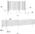
- the water-cooled wall tube group 4 includes a plurality of water-cooled wall tubes 41, a plurality of outlet centralise tubes 42 and a plurality of inlet centralise tubes 43; wherein a plurality of the water-cooled wall tubes 41 are disposed side-by-side and the water-cooled wall tubes 41 spirally coiled in an equally pitched helix in the axial direction along the casing 200; on each end of each the water-cooled wall tubes 41 is disposed with the second inlet guide tube 411 and the second outlet guide tube 412 respectively; and a plurality of the second outlet guide tubes 412 are connected to the outlet centralise tubes 42; a plurality of the second inlet guide tubes 411 are connected to an inlet centralise tube 43.
- a plurality of water-cooled wall tubes 41 are disposed side-by-side in an upward and downward direction, and are coiled inside the shell 200 at the end of the second inlet guide tubes 411 in accordance with an equal-pitch helical ascent and are disposed at the circumference of the coil assembly 1.
- Each of the water-cooled wall tube 41 inlet end connected to the second inlet guide tube 411, the liquid outlet end connected to the second outlet guide tube 412; a plurality of the second outlet guide tubes 412 are connected to the outlet centralise tube 42; a plurality of the second inlet guide tube 411 are connected to the inlet centralise tube 43.
- the water-cooled wall tube group 4 not only can lower the wall temperature of shell 200, but also can be able to recycle heat to produce a certain amount of saturated steam, and the water-cooled wall tube 41 are made of the carbon steel or low alloy steel non-ferrous steel,which is not only a good energy saving parts, but also a good energy saving method.
- the highest point of a plurality of the water-cooled wall tubes 41 in the axial direction of the shell 200 is in the same plane, which can be understood as ensuring that the highest point of the water-cooled wall tubes 41 is in the same plane as far as possible to ensure that the wall temperature of the shell 200 is uniformly lowered, regardless of how many the water-cooled wall tubes 41 there are.
- the water-cooled wall tube group 4 comprises three water-cooled wall tubes 41, a first water-cooled wall tube, a second water-cooled wall tube and a third water-cooled wall tube in ascending order from the bottom to the top; wherein the first water-cooled wall tube, the second water-cooled wall tube and the third water-cooled wall tube are simultaneously coiled inside the shell 200 in an equally spaced spiral upward manner until they reach the uppermost part, in order to keep the highest point of the first water-cooled wall tube, the second water-cooled wall tube and the third water-cooled wall tube in the same plane, the third water-cooled wall tube first ends its coiling and extends downwardly to connect with the outlet centralise tube 42; then the second water-cooled wall tube ends its coiling and extends downwardly to connect with the outlet centralise tube 42; and lastly the third water-cooled wall tube ends its coiling and extends downwardly to connect with the outlet centralise tube 42.
- the highest point of the a plurality of water-cooled wall tubes in the same plane of the first water-cooled wall tube, the second water-cooled wall tube, and the third water-cooled wall tube extends downward at the position close to the circumferential evenly distributed, which can effectively reduce the temperature difference on the shell 200 in the same plane so as to homogenise the temperature of the wall of the shell 200, and increase the lifespan of the shell 200.
- the above setup is an exemplary but non-limiting description.
- the heat recycling unit 100 comprises a guard cylinder 45; the guard cylinder 45 is disposed on the outer circumferential edge of the coil assembly 1 and between the coil assembly 1 and the water-cooled wall tube group 4.
- a guard cylinder 45 is disposed on the entire outer circumference of the coil assembly 1, and the function of the guard cylinder 45 is to ensure that the maximum amount of heat flow passes through the various layers of the coil 11 of the coil assembly 1 from top to bottom, preventing short-circuiting of the heat flow and minimising the flow of the heat flow to the inner wall of the shell 200, so as to maximise heat recycling and to protect the inner wall of the shell 200.
- the combustion unit 500 further comprises a support assembly 51 for supporting the fixed platinum mesh layer 501; the support assembly 51 comprises a support member, the support member is disposed underneath the platinum mesh layer 501 for supporting the platinum mesh layer 501.
- the support structure comprises a base 512 at least, the base 512 being disposed underneath an outer edge of the platinum mesh layer 501.
- the support structure further comprises a grid support frame 502 disposed below the platinum mesh layer 501.
- the grid support frame 502 is made of a high temperature resistant duplex alloy steel material and is fabricated from a forging turning process.
- the support assembly 51 comprises a support member, using the support member to be provided below the platinum mesh layer 501, and the support assembly 51 further comprises an elastic compression device.
- the elastic compression device comprises a gasket 513, an inverted T-shaped support ring, an elastic snap ring 516, and a cylinder section 514, exemplarily as shown in FIG.
- the gasket 513 is disposed at each side of the top and bottom of the platinum mesh layer 501; wherein the inverted T-shaped support ring is disposed on an external part of the hollow circular cylinder section 514, which can be understood to be a heat-resistant alloy; an elastic snap ring 516 is disposed on the overhead of the inverted T-shaped support ring; and the inverted T-shaped support ring, the elastic snap ring 516, and the hollow circular cylinder section 514 are overlapping in the central axis; the pressure strip 401 welded on the lower cylinder inside the top cover 400 is connected with the elastic snap ring 516.
- the inverted T-shaped support ring comprises a support circle 515 and a support ring 517; wherein the support circle 515 is fixedly disposed on the outside of the hollow circular cylinder section 514, and in some embodiments the support circle 515 is welded-fixed to the outside of the cylinder section 514; the support ring 517 is fixedly disposed on top of the support circle 515, and it is known that the diameter of the support circle 517 is shorter than that of the support ring 515; the support ring 517 is vertically welded and fixed in the middle of the support ring 515; the elastic snap ring 516 is snap-fitted to the support ring 517, the elastic snap ring 516 has a gap between the end of the elastic snap ring 516 close to the cylinder section 514 and the cylinder section 514, and the diameter of the elastic snap ring 516 is larger than the diameter of the support ring 515.
- a platinum mesh compression ring 511 is provided between the gasket 513 and the cylinder section 514.
- the pressure strip 401 welded on the lower cylinder of the top cover 400 contacts the elastic ity ring 516, and presses the elastic ity ring 516 downward at the end away from the cylinder section 514, forming an elastic deformation to achieve the seal while pressurising and fixing the platinum mesh layer 501, and the platinum mesh layer 501 will further be sealed when the temperature inside the ammonia oxidation reactor 1000 increases, and will further expand by its own elastic ity through thermal micro-expansion, and at the same time, the elastic snap ring 516 coordinates to offset part of the thermal expansion deformation through its own elastic deformation, so as to protect the entire structure from being thermally extruded and deformed or damaged.
- the combustion unit 500 further comprises a gas distributor 52; wherein the gas distributor 52 is disposed inside the furnace chamber 300.
- the gas distributor 52 can be understood as a three-stage gas distributor, the main part of the gas distributor 52 is made of stainless steel plate, and is set up inside the furnace chamber 300 by using a hanging rod for lifting and supporting, and its function is to mix the incoming mixture of ammonia and air again and evenly distribute it to the platinum mesh layer 501 in the lower part, so that the ammonia oxidation reaction is more effective and sufficient.
- the three-stage gas distributor comprises a first distributor, a second distributor, and a third distributor set sequentially from top to bottom; the first distributor, the second distributor, and the third distributor are set with a regular distribution of the distribution holes, wherein the distribution holes of the first distributor and the second distributor have the same diameter; the distribution holes of the third distributor have a diameter smaller than that of the second distributor.
- the combustion unit 500 further comprises a deflector cone 53; wherein the deflector cone 53 is disposed on the top cover 400 and inside the furnace chamber 300, and the gas distributor 52 is disposed inside the deflector cone 53 for evenly distributing the mixture of ammonia and air over the platinum mesh layer 501.
- a deflector cone 53 can be disposed on the circumference of the gas distributor 52, so that the mixture of ammonia and air flows and mixes again in the deflector cone 53, and by limiting the hot gas flow in the deflector cone 53, the mixture of ammonia and air is maximally allowed to pass through the gas distributor 52, so as to achieve an even distribution of the mixture of ammonia and air that enters into the furnace chamber 300 to the platinum mesh layer 501 so that the ammonia oxygenation reaction is more complete and sufficient.
- the combustion unit 500 further comprises an ignition assembly 54; wherein the ignition assembly 54 comprises an igniter 541, an ignition distribution tube 542, and an ignition gas tube 543; wherein the igniter 541 ignites an ignition gas that is passed through the ignition gas tube 543, and uses the ignition distribution tube 542 to ignite the entire platinum mesh layer 501.
- the ignition assembly 54 comprises an igniter 541, an ignition distribution tube 542, and an ignition gas tube 543; wherein the igniter 541 ignites an ignition gas that is passed through the ignition gas tube 543, and uses the ignition distribution tube 542 to ignite the entire platinum mesh layer 501.
- an igniter 541 is disposed on the top cover 400, and in some embodiments, the igniter 541 is an electronic lighter, disposed above the ignition distribution tube 542, and the igniter 541 ignites the ignition gas; wherein a fire-breathing hole is disposed underneath the ignition distribution tube 542, so as to make the flame generated by the ignition gas dispersed downward to ignite the entire surface of the platinum mesh layer 501, and ignite the ammonia gas as evenly as possible.
- the embodiment of the application has an ignition gas passed through the ignition gas tube 543, wherein the ignition gas can be interpreted as hydrogen, which can realise the hydrogen combustion fire-breathing.
- the top cover 400 is equipped with at least one viewing window 55 for observing the combustion within the furnace chamber 300. In some embodiments, the top cover 400 is disposed with one or more viewing windows 55, wherein the observation of the combustion within the furnace chamber 300 is carried out by means of a sight glass in the viewing window 55
- the combustion in the furnace chamber 300 can also be checked by the installation of the observation window 55, and if the combustion in the furnace chamber 300 is unsatisfactory, the ignition assembly 54 can be used to re-ignite the ignition or by adjusting the amount of the ignition gas so as to adjust the combustion coverage.
- the top cover 400 is disposed with a protective air duct; for supplying a protective gas into the furnace chamber 300 to prevent high temperatures in the dead zone.
- embodiments of the application also disclose a process for producing nitric acid, which process may be realised by the system of the application and/or other replaceable components.
- the process of the application is realised by using individual components of the system of the application.
- the process comprises the following steps, as shown in FIG. 11 :
- the ammonia-air mixture is evenly distributed to the whole first space through the distribution of the gas distributor 52 and the infusion of the infusion cone 53, and then downward evenly distributed on the whole platinum mesh layer 501 catalyst surface and contact the platinum mesh layer 501 occuring the oxidation reaction, that is, after the ignition is successfully ignited, the ammonia-air mixture occurred in the exothermic combustion reaction under the catalysis of the platinum, and the platinum mesh layer 501 continues to release the heat in the nearby area, and the red light can be observed, and in addition the platinum mesh layer 501 is composed of many layers, mainly platinum elements, but it is necessary to explain: each layer of the elements are not necessarily the same, the general platinum mesh layer also contains palladium, rhodium and other elements; of which palladium elements can adsorb platinum, palladium element is conducive to reducing the platinum loss; rhodium element can be added to solidify platinum mesh to reduce the deformation of the increase in the contact area; in sum, palladium, rhodium and other elements to join
- the NO obtained from the oxidation reaction is the raw gas required for the production of nitric acid, which needs to be further reacted and converted into NO 2 in the subsequent processes and equipment, and then absorbed with water to generate nitric acid and purified to achieve the required concentration of the product.
- the oxidation of ammonia to produce nitrogen oxides is a strong exothermic reaction, the heat released from the reaction will cause the reaction temperature to continue to rise, the maximum temperature can reach 800-1000 °C. In addition to maintaining the oxidation reaction, the excess heat recycling is necessary.
- close the ignition gas tube 543 to stop the hydrogen input.
- the 800-1000°C hot gas stream comprising nitrogen oxides migrates in a downward flow to the second space, where the heat recycling in the hot gas stream is carried out by using the heat recycling unit 100.
- the hot gas stream is gradually reduced to 350-450°C after undergoing heat exchange and is then released into a post-process.
- first and second are used for descriptive purposes only and are not to be understood as indicating or implying relative importance or implicitly specifying the number of technical features indicated. Thus, a feature defined with “first”, “second” may expressly or implicitly include one or more such features. In the description of the application, “more than one” means two or more, unless otherwise expressly limited in some embodiments.
- connection shall be broadly construed, e.g., may be fixed or detachable or integral; may be mechanically or electrically connected; may be directly connected or connected through an intermediary; or may be directly connected or connected through an intermediary.
- connection shall be fixed or detachable or integral; may be mechanically or electrically connected; may be directly connected or connected through an intermediary; or may be directly connected or connected through an intermediary.
- the first feature being “above” or “below” the second feature may be a direct contact between the first and second features, or an indirect contact between the first and second features through an intermediate medium.
- the first feature being “above”, “upper” and “ over” the second feature may be that the first feature is directly above or diagonally above the second feature, or may simply mean that the first feature is horizontally higher than the second feature.
- the first feature is “below”, “under” and “underneath” the second feature may be that the first feature is directly below or diagonally below the second feature, or may simply mean that the first feature is less horizontal than the second feature.
Landscapes
- Chemical & Material Sciences (AREA)
- Organic Chemistry (AREA)
- Chemical Kinetics & Catalysis (AREA)
- Inorganic Chemistry (AREA)
- Physics & Mathematics (AREA)
- Thermal Sciences (AREA)
- Physical Or Chemical Processes And Apparatus (AREA)
Applications Claiming Priority (3)
| Application Number | Priority Date | Filing Date | Title |
|---|---|---|---|
| CN202123220675.1U CN216614056U (zh) | 2021-12-20 | 2021-12-20 | 一种弹性固定式铂网支撑固定机构 |
| CN202111564430.2A CN114370772B (zh) | 2021-12-20 | 2021-12-20 | 一种氧化炉换热组件 |
| PCT/CN2022/140168 WO2023116648A1 (zh) | 2021-12-20 | 2022-12-19 | 一种生产硝酸的氨氧化反应器及方法 |
Publications (2)
| Publication Number | Publication Date |
|---|---|
| EP4455079A1 true EP4455079A1 (de) | 2024-10-30 |
| EP4455079A4 EP4455079A4 (de) | 2025-03-05 |
Family
ID=86901351
Family Applications (1)
| Application Number | Title | Priority Date | Filing Date |
|---|---|---|---|
| EP22909960.1A Pending EP4455079A4 (de) | 2021-12-20 | 2022-12-19 | Ammoxidationsreaktor und verfahren zur herstellung von salpetersäure |
Country Status (2)
| Country | Link |
|---|---|
| EP (1) | EP4455079A4 (de) |
| WO (1) | WO2023116648A1 (de) |
Families Citing this family (1)
| Publication number | Priority date | Publication date | Assignee | Title |
|---|---|---|---|---|
| CN119838514B (zh) * | 2024-12-27 | 2025-10-31 | 太原理工大学 | 一种强效预混式防偏流固定床反应器 |
Family Cites Families (8)
| Publication number | Priority date | Publication date | Assignee | Title |
|---|---|---|---|---|
| CN201971639U (zh) * | 2011-03-31 | 2011-09-14 | 四川久源机械制造有限公司 | 一种年产30万吨硝酸用氧化炉 |
| CN102424370B (zh) * | 2011-09-26 | 2013-07-31 | 四川久源机械制造有限公司 | 年产36万吨的双加压法硝酸用氧化炉 |
| DE102011122142A1 (de) * | 2011-12-22 | 2013-06-27 | Thyssenkrupp Uhde Gmbh | Verfahren und Vorrichtung zur Herstellung von Salpetersäure |
| CN213505991U (zh) * | 2020-08-04 | 2021-06-22 | 四川久源机械制造有限公司 | 一种硝酸生产用氨氧化炉的水冷壁管组 |
| CN111892025A (zh) * | 2020-08-04 | 2020-11-06 | 四川久源机械制造有限公司 | 一种用于常压法生产硝酸的氨氧化炉及其工艺方法 |
| CN216745500U (zh) * | 2021-12-20 | 2022-06-14 | 赛鼎工程有限公司 | 一种氧化炉盘管组件 |
| CN114370772B (zh) * | 2021-12-20 | 2024-03-22 | 赛鼎工程有限公司 | 一种氧化炉换热组件 |
| CN216614056U (zh) * | 2021-12-20 | 2022-05-27 | 赛鼎工程有限公司 | 一种弹性固定式铂网支撑固定机构 |
-
2022
- 2022-12-19 WO PCT/CN2022/140168 patent/WO2023116648A1/zh not_active Ceased
- 2022-12-19 EP EP22909960.1A patent/EP4455079A4/de active Pending
Also Published As
| Publication number | Publication date |
|---|---|
| WO2023116648A1 (zh) | 2023-06-29 |
| EP4455079A4 (de) | 2025-03-05 |
Similar Documents
| Publication | Publication Date | Title |
|---|---|---|
| US12098079B2 (en) | Chemical reactor with integrated heat exchanger, heater, and high conductance catalyst holder | |
| US3958951A (en) | Convective power reformer equipment and system | |
| US5567398A (en) | Endothermic reaction apparatus and method | |
| US8622736B2 (en) | Recuperator burner having flattened heat exchanger pipes | |
| US5477846A (en) | Furnace-heat exchanger preheating system | |
| US4849187A (en) | Steam reforming apparatus | |
| EP4455079A1 (de) | Ammoxidationsreaktor und verfahren zur herstellung von salpetersäure | |
| WO2016119224A1 (zh) | 一种等温低温变换炉及变换工艺 | |
| EP2830994B1 (de) | Dampfreformierungsofen und verfahren dafür | |
| US5199961A (en) | Apparatus for catalytic reaction | |
| CN111892025A (zh) | 一种用于常压法生产硝酸的氨氧化炉及其工艺方法 | |
| US6153152A (en) | Endothermic reaction apparatus and method | |
| US5931658A (en) | Fuel cell power plant furnace | |
| US9242216B2 (en) | Apparatus for minimizing bypass in ammonia oxidation burners of industrial plants with burner diameters of 2-7 M in natural- or forced-circulation boilers | |
| CA1091425A (en) | Convective power reformer equipment and system | |
| CN201971639U (zh) | 一种年产30万吨硝酸用氧化炉 | |
| RU2845184C2 (ru) | Реактор окисления аммиака и способ получения азотной кислоты | |
| KR101194244B1 (ko) | 수증기 개질기 | |
| CN216745500U (zh) | 一种氧化炉盘管组件 | |
| CN102424370B (zh) | 年产36万吨的双加压法硝酸用氧化炉 | |
| CN114370772B (zh) | 一种氧化炉换热组件 | |
| EP4434615A1 (de) | Verfahren zur herstellung eines wasserstoff enthaltenden synthesegasprodukts | |
| CN202336326U (zh) | 一种管壳式换热转化器 | |
| CN201770479U (zh) | 一种双加压法硝酸生产用新型氧化炉 | |
| CN108786666B (zh) | 侧烧转化炉 |
Legal Events
| Date | Code | Title | Description |
|---|---|---|---|
| STAA | Information on the status of an ep patent application or granted ep patent |
Free format text: STATUS: THE INTERNATIONAL PUBLICATION HAS BEEN MADE |
|
| PUAI | Public reference made under article 153(3) epc to a published international application that has entered the european phase |
Free format text: ORIGINAL CODE: 0009012 |
|
| STAA | Information on the status of an ep patent application or granted ep patent |
Free format text: STATUS: REQUEST FOR EXAMINATION WAS MADE |
|
| 17P | Request for examination filed |
Effective date: 20240709 |
|
| AK | Designated contracting states |
Kind code of ref document: A1 Designated state(s): AL AT BE BG CH CY CZ DE DK EE ES FI FR GB GR HR HU IE IS IT LI LT LU LV MC ME MK MT NL NO PL PT RO RS SE SI SK SM TR |
|
| A4 | Supplementary search report drawn up and despatched |
Effective date: 20250204 |
|
| RIC1 | Information provided on ipc code assigned before grant |
Ipc: B01J 19/32 20060101ALI20250129BHEP Ipc: B01J 15/00 20060101ALI20250129BHEP Ipc: C01B 21/38 20060101AFI20250129BHEP |
|
| DAV | Request for validation of the european patent (deleted) | ||
| DAX | Request for extension of the european patent (deleted) | ||
| GRAP | Despatch of communication of intention to grant a patent |
Free format text: ORIGINAL CODE: EPIDOSNIGR1 |
|
| STAA | Information on the status of an ep patent application or granted ep patent |
Free format text: STATUS: GRANT OF PATENT IS INTENDED |
|
| INTG | Intention to grant announced |
Effective date: 20250916 |
|
| GRAJ | Information related to disapproval of communication of intention to grant by the applicant or resumption of examination proceedings by the epo deleted |
Free format text: ORIGINAL CODE: EPIDOSDIGR1 |
|
| STAA | Information on the status of an ep patent application or granted ep patent |
Free format text: STATUS: REQUEST FOR EXAMINATION WAS MADE |