EP4455076A1 - Decarbonisation of a hydrotreatment plant - Google Patents
Decarbonisation of a hydrotreatment plant Download PDFInfo
- Publication number
- EP4455076A1 EP4455076A1 EP23169857.2A EP23169857A EP4455076A1 EP 4455076 A1 EP4455076 A1 EP 4455076A1 EP 23169857 A EP23169857 A EP 23169857A EP 4455076 A1 EP4455076 A1 EP 4455076A1
- Authority
- EP
- European Patent Office
- Prior art keywords
- stream
- gas
- gas stream
- tail
- produce
- Prior art date
- Legal status (The legal status is an assumption and is not a legal conclusion. Google has not performed a legal analysis and makes no representation as to the accuracy of the status listed.)
- Granted
Links
Images



Classifications
-
- C—CHEMISTRY; METALLURGY
- C01—INORGANIC CHEMISTRY
- C01B—NON-METALLIC ELEMENTS; COMPOUNDS THEREOF; METALLOIDS OR COMPOUNDS THEREOF NOT COVERED BY SUBCLASS C01C
- C01B3/00—Hydrogen; Gaseous mixtures containing hydrogen; Separation of hydrogen from mixtures containing it; Purification of hydrogen; Reversible storage of hydrogen
- C01B3/02—Production of hydrogen; Production of gaseous mixtures containing hydrogen
- C01B3/32—Production of hydrogen; Production of gaseous mixtures containing hydrogen by reaction of gaseous or liquid organic compounds with gasifying agents, e.g. water, carbon dioxide or air
- C01B3/34—Production of hydrogen; Production of gaseous mixtures containing hydrogen by reaction of gaseous or liquid organic compounds with gasifying agents, e.g. water, carbon dioxide or air by reaction of hydrocarbons with gasifying agents
- C01B3/38—Production of hydrogen; Production of gaseous mixtures containing hydrogen by reaction of gaseous or liquid organic compounds with gasifying agents, e.g. water, carbon dioxide or air by reaction of hydrocarbons with gasifying agents using catalysts
-
- C—CHEMISTRY; METALLURGY
- C01—INORGANIC CHEMISTRY
- C01B—NON-METALLIC ELEMENTS; COMPOUNDS THEREOF; METALLOIDS OR COMPOUNDS THEREOF NOT COVERED BY SUBCLASS C01C
- C01B3/00—Hydrogen; Gaseous mixtures containing hydrogen; Separation of hydrogen from mixtures containing it; Purification of hydrogen; Reversible storage of hydrogen
- C01B3/02—Production of hydrogen; Production of gaseous mixtures containing hydrogen
- C01B3/06—Production of hydrogen; Production of gaseous mixtures containing hydrogen by reaction of inorganic compounds containing electro-positively bound hydrogen with inorganic reducing agents
- C01B3/12—Production of hydrogen; Production of gaseous mixtures containing hydrogen by reaction of inorganic compounds containing electro-positively bound hydrogen with inorganic reducing agents by reaction of water vapour with carbon monoxide
- C01B3/16—Production of hydrogen; Production of gaseous mixtures containing hydrogen by reaction of inorganic compounds containing electro-positively bound hydrogen with inorganic reducing agents by reaction of water vapour with carbon monoxide using catalysts
-
- C—CHEMISTRY; METALLURGY
- C01—INORGANIC CHEMISTRY
- C01B—NON-METALLIC ELEMENTS; COMPOUNDS THEREOF; METALLOIDS OR COMPOUNDS THEREOF NOT COVERED BY SUBCLASS C01C
- C01B3/00—Hydrogen; Gaseous mixtures containing hydrogen; Separation of hydrogen from mixtures containing it; Purification of hydrogen; Reversible storage of hydrogen
- C01B3/02—Production of hydrogen; Production of gaseous mixtures containing hydrogen
- C01B3/32—Production of hydrogen; Production of gaseous mixtures containing hydrogen by reaction of gaseous or liquid organic compounds with gasifying agents, e.g. water, carbon dioxide or air
- C01B3/34—Production of hydrogen; Production of gaseous mixtures containing hydrogen by reaction of gaseous or liquid organic compounds with gasifying agents, e.g. water, carbon dioxide or air by reaction of hydrocarbons with gasifying agents
- C01B3/36—Production of hydrogen; Production of gaseous mixtures containing hydrogen by reaction of gaseous or liquid organic compounds with gasifying agents, e.g. water, carbon dioxide or air by reaction of hydrocarbons with gasifying agents using oxygen; using mixtures containing oxygen as gasifying agents
-
- C—CHEMISTRY; METALLURGY
- C01—INORGANIC CHEMISTRY
- C01B—NON-METALLIC ELEMENTS; COMPOUNDS THEREOF; METALLOIDS OR COMPOUNDS THEREOF NOT COVERED BY SUBCLASS C01C
- C01B3/00—Hydrogen; Gaseous mixtures containing hydrogen; Separation of hydrogen from mixtures containing it; Purification of hydrogen; Reversible storage of hydrogen
- C01B3/02—Production of hydrogen; Production of gaseous mixtures containing hydrogen
- C01B3/32—Production of hydrogen; Production of gaseous mixtures containing hydrogen by reaction of gaseous or liquid organic compounds with gasifying agents, e.g. water, carbon dioxide or air
- C01B3/34—Production of hydrogen; Production of gaseous mixtures containing hydrogen by reaction of gaseous or liquid organic compounds with gasifying agents, e.g. water, carbon dioxide or air by reaction of hydrocarbons with gasifying agents
- C01B3/38—Production of hydrogen; Production of gaseous mixtures containing hydrogen by reaction of gaseous or liquid organic compounds with gasifying agents, e.g. water, carbon dioxide or air by reaction of hydrocarbons with gasifying agents using catalysts
- C01B3/382—Processes with two or more reaction steps, of which at least one is catalytic, e.g. steam reforming and partial oxidation
-
- C—CHEMISTRY; METALLURGY
- C01—INORGANIC CHEMISTRY
- C01B—NON-METALLIC ELEMENTS; COMPOUNDS THEREOF; METALLOIDS OR COMPOUNDS THEREOF NOT COVERED BY SUBCLASS C01C
- C01B3/00—Hydrogen; Gaseous mixtures containing hydrogen; Separation of hydrogen from mixtures containing it; Purification of hydrogen; Reversible storage of hydrogen
- C01B3/50—Separation of hydrogen or hydrogen-containing gases from gaseous mixtures, e.g. purification
- C01B3/56—Separation of hydrogen or hydrogen-containing gases from gaseous mixtures, e.g. purification by contacting with solids; Regeneration of used solids
-
- C—CHEMISTRY; METALLURGY
- C10—PETROLEUM, GAS OR COKE INDUSTRIES; TECHNICAL GASES CONTAINING CARBON MONOXIDE; FUELS; LUBRICANTS; PEAT
- C10G—CRACKING HYDROCARBON OILS; PRODUCTION OF LIQUID HYDROCARBON MIXTURES, e.g. BY DESTRUCTIVE HYDROGENATION, OLIGOMERISATION, POLYMERISATION; RECOVERY OF HYDROCARBON OILS FROM OIL-SHALE, OIL-SAND, OR GASES; REFINING MIXTURES MAINLY CONSISTING OF HYDROCARBONS; REFORMING OF NAPHTHA; MINERAL WAXES
- C10G49/00—Treatment of hydrocarbon oils, in the presence of hydrogen or hydrogen-generating compounds, not provided for in a single one of groups C10G45/02, C10G45/32, C10G45/44, C10G45/58 or C10G47/00
- C10G49/007—Treatment of hydrocarbon oils, in the presence of hydrogen or hydrogen-generating compounds, not provided for in a single one of groups C10G45/02, C10G45/32, C10G45/44, C10G45/58 or C10G47/00 in the presence of hydrogen from a special source or of a special composition or having been purified by a special treatment
-
- C—CHEMISTRY; METALLURGY
- C10—PETROLEUM, GAS OR COKE INDUSTRIES; TECHNICAL GASES CONTAINING CARBON MONOXIDE; FUELS; LUBRICANTS; PEAT
- C10K—PURIFYING OR MODIFYING THE CHEMICAL COMPOSITION OF COMBUSTIBLE GASES CONTAINING CARBON MONOXIDE
- C10K3/00—Modifying the chemical composition of combustible gases containing carbon monoxide to produce an improved fuel, e.g. one of different calorific value, which may be free from carbon monoxide
- C10K3/02—Modifying the chemical composition of combustible gases containing carbon monoxide to produce an improved fuel, e.g. one of different calorific value, which may be free from carbon monoxide by catalytic treatment
- C10K3/04—Modifying the chemical composition of combustible gases containing carbon monoxide to produce an improved fuel, e.g. one of different calorific value, which may be free from carbon monoxide by catalytic treatment reducing the carbon monoxide content, e.g. water-gas shift [WGS]
-
- C—CHEMISTRY; METALLURGY
- C01—INORGANIC CHEMISTRY
- C01B—NON-METALLIC ELEMENTS; COMPOUNDS THEREOF; METALLOIDS OR COMPOUNDS THEREOF NOT COVERED BY SUBCLASS C01C
- C01B2203/00—Integrated processes for the production of hydrogen or synthesis gas
- C01B2203/02—Processes for making hydrogen or synthesis gas
- C01B2203/0205—Processes for making hydrogen or synthesis gas containing a reforming step
- C01B2203/0227—Processes for making hydrogen or synthesis gas containing a reforming step containing a catalytic reforming step
- C01B2203/0233—Processes for making hydrogen or synthesis gas containing a reforming step containing a catalytic reforming step the reforming step being a steam reforming step
-
- C—CHEMISTRY; METALLURGY
- C01—INORGANIC CHEMISTRY
- C01B—NON-METALLIC ELEMENTS; COMPOUNDS THEREOF; METALLOIDS OR COMPOUNDS THEREOF NOT COVERED BY SUBCLASS C01C
- C01B2203/00—Integrated processes for the production of hydrogen or synthesis gas
- C01B2203/02—Processes for making hydrogen or synthesis gas
- C01B2203/0205—Processes for making hydrogen or synthesis gas containing a reforming step
- C01B2203/0227—Processes for making hydrogen or synthesis gas containing a reforming step containing a catalytic reforming step
- C01B2203/0244—Processes for making hydrogen or synthesis gas containing a reforming step containing a catalytic reforming step the reforming step being an autothermal reforming step, e.g. secondary reforming processes
-
- C—CHEMISTRY; METALLURGY
- C01—INORGANIC CHEMISTRY
- C01B—NON-METALLIC ELEMENTS; COMPOUNDS THEREOF; METALLOIDS OR COMPOUNDS THEREOF NOT COVERED BY SUBCLASS C01C
- C01B2203/00—Integrated processes for the production of hydrogen or synthesis gas
- C01B2203/02—Processes for making hydrogen or synthesis gas
- C01B2203/025—Processes for making hydrogen or synthesis gas containing a partial oxidation step
- C01B2203/0255—Processes for making hydrogen or synthesis gas containing a partial oxidation step containing a non-catalytic partial oxidation step
-
- C—CHEMISTRY; METALLURGY
- C01—INORGANIC CHEMISTRY
- C01B—NON-METALLIC ELEMENTS; COMPOUNDS THEREOF; METALLOIDS OR COMPOUNDS THEREOF NOT COVERED BY SUBCLASS C01C
- C01B2203/00—Integrated processes for the production of hydrogen or synthesis gas
- C01B2203/02—Processes for making hydrogen or synthesis gas
- C01B2203/0283—Processes for making hydrogen or synthesis gas containing a CO-shift step, i.e. a water gas shift step
- C01B2203/0288—Processes for making hydrogen or synthesis gas containing a CO-shift step, i.e. a water gas shift step containing two CO-shift steps
-
- C—CHEMISTRY; METALLURGY
- C01—INORGANIC CHEMISTRY
- C01B—NON-METALLIC ELEMENTS; COMPOUNDS THEREOF; METALLOIDS OR COMPOUNDS THEREOF NOT COVERED BY SUBCLASS C01C
- C01B2203/00—Integrated processes for the production of hydrogen or synthesis gas
- C01B2203/04—Integrated processes for the production of hydrogen or synthesis gas containing a purification step for the hydrogen or the synthesis gas
- C01B2203/042—Purification by adsorption on solids
- C01B2203/043—Regenerative adsorption process in two or more beds, one for adsorption, the other for regeneration
-
- C—CHEMISTRY; METALLURGY
- C01—INORGANIC CHEMISTRY
- C01B—NON-METALLIC ELEMENTS; COMPOUNDS THEREOF; METALLOIDS OR COMPOUNDS THEREOF NOT COVERED BY SUBCLASS C01C
- C01B2203/00—Integrated processes for the production of hydrogen or synthesis gas
- C01B2203/06—Integration with other chemical processes
- C01B2203/063—Refinery processes
- C01B2203/065—Refinery processes using hydrotreating, e.g. hydrogenation, hydrodesulfurisation
-
- C—CHEMISTRY; METALLURGY
- C01—INORGANIC CHEMISTRY
- C01B—NON-METALLIC ELEMENTS; COMPOUNDS THEREOF; METALLOIDS OR COMPOUNDS THEREOF NOT COVERED BY SUBCLASS C01C
- C01B2203/00—Integrated processes for the production of hydrogen or synthesis gas
- C01B2203/08—Methods of heating or cooling
- C01B2203/0805—Methods of heating the process for making hydrogen or synthesis gas
- C01B2203/0811—Methods of heating the process for making hydrogen or synthesis gas by combustion of fuel
- C01B2203/0822—Methods of heating the process for making hydrogen or synthesis gas by combustion of fuel the fuel containing hydrogen
-
- C—CHEMISTRY; METALLURGY
- C01—INORGANIC CHEMISTRY
- C01B—NON-METALLIC ELEMENTS; COMPOUNDS THEREOF; METALLOIDS OR COMPOUNDS THEREOF NOT COVERED BY SUBCLASS C01C
- C01B2203/00—Integrated processes for the production of hydrogen or synthesis gas
- C01B2203/08—Methods of heating or cooling
- C01B2203/0805—Methods of heating the process for making hydrogen or synthesis gas
- C01B2203/0811—Methods of heating the process for making hydrogen or synthesis gas by combustion of fuel
- C01B2203/0827—Methods of heating the process for making hydrogen or synthesis gas by combustion of fuel at least part of the fuel being a recycle stream
-
- C—CHEMISTRY; METALLURGY
- C01—INORGANIC CHEMISTRY
- C01B—NON-METALLIC ELEMENTS; COMPOUNDS THEREOF; METALLOIDS OR COMPOUNDS THEREOF NOT COVERED BY SUBCLASS C01C
- C01B2203/00—Integrated processes for the production of hydrogen or synthesis gas
- C01B2203/14—Details of the flowsheet
- C01B2203/142—At least two reforming, decomposition or partial oxidation steps in series
-
- C—CHEMISTRY; METALLURGY
- C10—PETROLEUM, GAS OR COKE INDUSTRIES; TECHNICAL GASES CONTAINING CARBON MONOXIDE; FUELS; LUBRICANTS; PEAT
- C10G—CRACKING HYDROCARBON OILS; PRODUCTION OF LIQUID HYDROCARBON MIXTURES, e.g. BY DESTRUCTIVE HYDROGENATION, OLIGOMERISATION, POLYMERISATION; RECOVERY OF HYDROCARBON OILS FROM OIL-SHALE, OIL-SAND, OR GASES; REFINING MIXTURES MAINLY CONSISTING OF HYDROCARBONS; REFORMING OF NAPHTHA; MINERAL WAXES
- C10G2300/00—Aspects relating to hydrocarbon processing covered by groups C10G1/00 - C10G99/00
- C10G2300/40—Characteristics of the process deviating from typical ways of processing
- C10G2300/4056—Retrofitting operations
Definitions
- the present invention relates to a method for reducing the carbon dioxide emissions of a hydrotreatment plant.
- Hydrotreating is a term used to refer to the catalytic treatment of a feedstock in the presence of hydrogen as part of processes to remove materials such as sulfur, nitrogen, olefins and aromatics. Hydrotreatment is often carried out on petroleum fractions as the first step of a wider refinery process.
- a review of hydrotreating is provided in Handbook of Petroleum Processing pp321-354 - Chapter 8 "Hydrotreating" by A. Gruia .
- a hydrotreater is often a component of a refinery with hydrogen for the hydrotreater generated in a H 2 production unit elsewhere on the refinery.
- a hydrocarbon-containing by-product stream generated by the refinery is sometimes treated in a H 2 production unit to generate hydrogen for the hydrotreater.
- WO2009/151690A2 describes a process involving treatment of a renewable feedstock by hydrogenating, deoxygenating, isomerizing and selectively hydrocracking the renewable feedstock in the presence of hydrogen and a catalyst to produce a reaction effluent.
- the reaction effluent is treated by separating the water, carbon oxides, light hydrocarbon gasses and hydrogen to generate a stream comprising paraffinic hydrocarbons, which is then separated into a hydrocarbon product comprising hydrocarbons having boiling points in the aviation fuel range, an overhead stream comprising naphtha, and a bottoms stream.
- certain components of the reaction effluent are separated and conducted to a steam reforming zone to produce hydrogen which is used in the hydrotreatment.
- WO2021/180805A1 describes a process involving passing a feedstock originating from a renewable source through a hydroprocessing stage for producing a main hydrotreated stream.
- the main hydrotreated stream is separated into an aqueous stream, a hydrogen-rich stream and an off-gas stream comprising hydrocarbons.
- the hydrogen-rich stream is recycled to the hydroprocessing stage.
- the off-gas stream is passed to a hydrogen producing unit where it is used to produce a make-up hydrogen stream for the hydroprocessing stage.
- the invention in a first aspect relates to a method for retrofitting a chemical plant according to claim 1.
- the method involves installing a tail-gas treatment unit comprising: an autothermal reformer (ATR) or a partial oxidation (POX) reactor; a second water-gas shift (WGS) section; and a first COz removal unit.
- ATR autothermal reformer
- POX partial oxidation
- WGS water-gas shift
- COz removal unit a first COz removal unit
- the tail-gas treatment unit (TTU) is fed at least in part by the tail-gas stream produced by the hydrogen purification unit within the main reforming section and generates a crude H 2 product stream. At least a portion of the crude H 2 product stream is used as fuel in the fired reformer. A portion of the crude H 2 product stream may also be used as fuel for fired heaters to heat process streams elsewhere on the plant.
- the TTU can be designed for any capacity within a wide range as long as it takes as feed, as a minimum, the tail-gas from the existing hydrogen plant. Furthermore, the constituent tail-gas treatment process units can be over-sized in design, in order to future-proof the tail-gas treatment unit for future expansions in H 2 production. By replacing or eliminating hydrocarbon fuel for firing the fired reformer by generating Hz in the TTU, COz emissions from the fired reformer are greatly reduced.
- a benefit of introducing a TTU is that it does not require modification of the main reforming section, by which we mean the section formed by the fired reformer, first water-gas shift section, first water separation unit and hydrogen purification unit.
- the main reforming section may be operated uninterrupted right up until the change-over, when the tail-gas produced by the hydrogen purification unit is diverted to provide feed for the TTU.
- the TTU can be cited remotely with pipelines running between the units.
- the method is particularly applicable to a scenario where the operator of a hydrotreatment facility wishes to change the feed from a non-biogenic feed (pre-retrofit) to a biogenic feed (post-retrofit). If the hydrotreater uses a biogenic fuel then combustion of off-gas from the hydrotreater as fuel in the SMR does not contribute to net COz emissions.
- biogenic feeds typically require significantly more H 2 for hydrotreatment compared to non-biogenic fuels and therefore require the steam reforming section to operate with a higher throughput to produce the larger amounts of Hz required for the hydrotreater. Installation of a TTU according to the present invention allows the necessary additional H 2 to be produced without increasing COz emissions.
- the invention in a second aspect relates to an integrated hydrogen and hydrotreatment plant according to claim 7.
- the plant may be produced by the retrofit method, or alternatively may be a grassroots plant.
- the invention relates to an integrated process for producing hydrogen and carrying out hydrotreatment according to claim 8.
- references herein to the "main reforming section” refer to the section comprising the fired reformer, first water-gas shift section, first water separation unit and hydrogen purification unit. It will be appreciated that intermediate stages of heating or cooling process streams may be present in between these stages.
- the role of the main reforming section is to generate a Hz product stream (typically ⁇ 99 vol% H 2 ). At least a portion of the H 2 product stream is used to provide the H 2 needed by the hydrotreating section.
- the hydrogen purification unit also produces a tail-gas stream which used to generate the tail-gas feedstock stream described below.
- a fired reformer also known as a steam methane reformer or SMR, typically comprises one or more tubes containing a steam reforming catalyst.
- the tubes are fed with a hydrocarbon feedstock stream which contains hydrocarbons (with methane being the predominant component) and steam.
- Heat for the endothermic steam reforming reactions taking place in the tubes ("tube side") is provided by combusting a fuel stream on the shell side of the reformer to produce a flue gas stream.
- the fuel stream is predominantly hydrocarbon based and, unless the flue gas stream is treated to remove carbon dioxide, results in the emission of COz.
- the fired reformer produces a first reformed gas stream.
- first is used simply to differentiate from the second reformed gas stream produced in the TTU.
- the fuel stream is provided at least in part by the crude H 2 stream.
- the first reformed gas stream is typically cooled before being fed to the first WGS section.
- the first WGS section includes one or more WGS shift stages and may include stages of high-temperature shift, medium-temperature shift, isothermal shift and low-temperature shift. These terms, as well as suitable catalysts therefore, are described in WO2022/003312A1 .
- the stream exiting the WGS unit is referred to as a first shifted gas stream and ideally comprises COz, H 2 , with the residual being steam, small amounts of unreacted methane and CO and inert gases.
- the first shifted gas stream is cooled to a temperature below the dew point so that the steam condenses to water. Any suitable technique may be used and such techniques for water removal are described in WO2022/003312A1 .
- the role of the hydrogen purification is to separate the first dewatered shifted gas stream into a H 2 product stream and a tail-gas stream.
- Any suitable purification unit may be used, but a preferred unit is a pressure swing adsorption (PSA) unit.
- PSD pressure swing adsorption
- the H 2 product stream typically and preferably has a purity of ⁇ 99 vol% H 2 . At least a portion of the H 2 product stream is used to provide the H 2 needed by the hydrotreating section.
- the role of the hydrotreating section is to carry out hydrotreatment on a hydrotreatment feedstock stream and produce a hydrotreated stream and an off-gas stream.
- the hydrotreating section includes a hydrotreater and may also include additional units such as for dewaxing, isomerisation and hydrocracking.
- the H 2 for each of these additional units is preferably provided by a portion of the product H 2 stream.
- off-gas streams may be produced from the additional units (including streams with low commercial value, such as those comprising C3-C5 hydrocarbons from a hydrocracker). These off-gas streams, optionally after having undergone treatment, may also be used to produce the tail-gas feedstock stream. Examples of treatment include purification to remove impurities such as sulfur compounds, or pre-reforming.
- the off-gas stream will have a lower sulfur content as compared to the hydrotreatment feedstock stream, in all embodiments of the invention it is preferred that the off-gas stream from the hydrotreater is first desulfurized to produce a desulfurized off-gas stream. Embodiments referring to the off-gas stream also apply to the desulfurized off-gas stream.
- the off-gas stream contains significant amounts of COz then it may be desirable to treat the off-gas stream in a third carbon dioxide separation unit, upstream of the TTU, which is arranged to accept the off-gas stream and produce a third carbon dioxide-containing stream and a purified off-gas stream.
- “third” is used to differentiate the carbon dioxide separation unit and the carbon dioxide-containing stream from the first and second carbon dioxide separation units and carbon dioxide-containing streams described in other sections.
- the purified off-gas stream may be used to produce the tail-gas feedstock stream.
- the retrofit method may therefore comprise installing a third carbon dioxide separation unit upstream of the TTU, the third carbon dioxide separation unit being arranged to accept the off-gas stream and produce a third carbon dioxide-containing stream and a purified off-gas stream. Removing carbon dioxide upstream of the TTU has the benefit of reducing the throughput through the TTU and may avoid having to oversize the TTU.
- the hydrotreatment feedstock stream is biogenic, i.e. it is derived from renewable sources rather than fossil fuel sources. If the hydrotreatment feedstock stream is biogenic then the off-gas may be used to provide the fuel gas without contribution to net COz emissions.
- the TTU comprises, sequentially: an autothermal reformer (ATR) or partial oxidation reactor (POX), a second water-gas shift section, and a first carbon dioxide separation unit. Additional units (e.g. heat exchangers, steam removal etc%) may also be present in the TTU.
- ATR autothermal reformer
- POX partial oxidation reactor
- Additional units e.g. heat exchangers, steam removal etc.
- the feed to the ATR or POX is referred to herein as the tail-gas feedstock stream.
- the tail-gas feedstock stream includes at least a portion of the tail-gas stream from the hydrogen purification unit, preferably all of the tail-gas stream. In this way the fuel stream to the fired reformer makes use of the crude Hz stream produced by the TTU rather than combusting the tail-gas stream, thereby lowering the COz content of the flue gas stream produced by the fired reformer.
- the tail-gas stream from the hydrogen purification unit may be used as the tail-gas feedstock stream directly, i.e. without altering its chemical composition. Because the tail-gas stream may still contain significant amounts of COz, in a preferred embodiment the tail-gas stream is treated in a second carbon dioxide separation unit upstream of the TTU to produce a second carbon dioxide-containing stream and a purified tail-gas stream.
- second is used to differentiate the carbon dioxide separation unit and the carbon dioxide-containing stream from the first and third carbon dioxide separation units and carbon dioxide-containing streams described in other sections.
- the retrofit method may therefore comprise installing a second carbon dioxide separation unit upstream of the TTU, the third carbon dioxide separation unit being arranged to accept the tail-gas stream and produce a second carbon dioxide-containing stream and a purified tail-gas stream.
- Removing carbon dioxide upstream of the TTU has the benefit of reducing the throughput through the TTU and may avoid having to oversize the TTU.
- the tail-gas stream is supplemented with at least a portion of the off-gas stream from the hydrotreating section to produce the tail-gas feedstock stream.
- the retrofit method may therefore comprise installing means for feeding at least a portion of the off-gas stream to produce the tail-gas feedstock stream.
- all of the off-gas stream from the hydrotreating section is used to produce the tail-gas feedstock stream. Passing some, preferably all of the tail-gas stream through the TTU is desirable if the goal is to minimise the COz content of the flue gas stream.
- ATR Autothermal reformer
- POX partial oxidation
- the role of the ATR or POX is to convert hydrocarbons in the tail-gas feedstock stream into hydrogen and carbon oxides through steam reforming reactions.
- the steam content of the tail-gas feedstock steam may be adjusted by steam addition prior to entering the ATR or POX reactor.
- An ATR generally comprises a burner disposed at the top of the reformer, to which the hydrocarbon-containing fuel stream and an oxygen-containing gas are fed, a combustion zone beneath the burner through which a flame extends, and a fixed bed of particulate steam reforming catalyst disposed below the combustion zone.
- the heat for the endothermic steam reforming reactions is therefore provided by combustion of a portion of hydrocarbon in the hydrocarbon-containing fuel stream.
- the hydrocarbon-containing fuel stream is typically fed to the top of the reformer and the oxygen-containing gas fed to the burner, mixing and combustion occur downstream of the burner generating a heated gas mixture the composition of which is brought to equilibrium as it passes through the steam reforming catalyst.
- Partial oxidation reactors are known and typically comprise a vessel to which the feed and an oxygen-containing gas are fed via a burner, analogous to that used in an autothermal reformer, disposed above a reaction chamber in which the partial combustion reactions take place. Unlike an autothermal reformer, a catalyst is not present in the vessel. Air, oxygen-enriched air or O 2 may be used as the oxygen-containing gas. The combustion temperature may be about 1300°C, or higher. Steam may be added to the feed and/or the oxygen containing gas to lower the combustion temperature and reduce soot formation.
- the idealised formula for this reaction applied to methane in the feed is as follows: 2 CH 4 + O 2 ⁇ 2CO + 4 Hz
- the TTU comprises an ATR.
- the stream exiting the POX or ATR is referred to herein as a second reformed gas stream.
- the TTU comprises a gas-heated reformer (GHR) in addition to the ATR or POX reactor.
- GHR gas-heated reformer
- the skilled person will be familiar with the design of gas-heated reformers and detail of their arrangement and suitable catalysts are described for instance in WO2022/003312A1 , GB1578270A , WO97/05947A1 and US4910228A .
- a GHR comprises one or more catalyst-filled tubes (defining a tube side), and is arranged so that hot gas passes over the outer surface of the tubes (a shell side) providing heat for the endothermic steam reforming reactions taking place tube side.
- hot gases from the outlet of the ATR or POX reactor are used as the hot gas on the shell-side of the GHR.
- the GHR and ATR or POX reactor can be arranged in any suitable arrangement, typically GHR followed by ATR or POX reactor with the hot gases then being sent to the GHR shell-side, although other arrangements are possible.
- the TTU does not include any reforming stage other than the ATR or POX reactor.
- the second reformed gas stream is typically cooled before being fed to the second WGS section.
- the second WGS section includes one or more WGS shift stages and may include stages of high-temperature shift, medium-temperature shift, isothermal shift and low-temperature shift. These terms, as well as suitable catalysts therefore, are described in WO2022/003312A1 .
- the stream exiting the WGS unit is referred to as a second shifted gas stream and ideally comprises COz, H 2 , with the residual being small amounts of methane and CO and inert gases.
- steam or water removal is carried out on the second shifted gas stream before it is sent to the first carbon dioxide separation unit.
- the second shifted gas stream is cooled to a temperature below the dew point so that the steam condenses. Suitable techniques for water removal are described in WO2022/003312A1 .
- the role of the first COz removal unit is to separate the second shifted gas stream into a first carbon dioxide-containing stream and a crude Hz stream.
- Any suitable COz separation technology may be used and the skilled person will be aware of suitable technologies. Examples include physical wash systems, reactive wash systems (e.g. an amine wash system) and cryogenic systems.
- the carbon dioxide-containing stream produced by the first, second and/or third COz removal units may be a relatively pure stream of COz gas (e.g. where the COz removal unit operates by cryogenic separation).
- carbon dioxide-containing stream should be understood in a broad sense.
- Preferred COz removal units operate by means of a wash system, for example an amine wash, and produce a CO 2 -laden adsorbent; the term "carbon dioxide-containing stream” should be understood to encompass such laden sorbent streams.
- the first, second and third carbon-dioxide containing streams may be processed separately to produce relatively pure carbon dioxide streams. Alternatively, one or more of these carbon-dioxide containing streams may be combined before being processed. Regenerated adsorbent is then returned to the COz removal units.
- the crude H 2 stream is used, at least in part, to provide the fuel stream for the fired reformer.
- the TTU may produce the crude H 2 stream in an amount in excess of what is required to fuel the fired reformer.
- the crude Hz stream is split into a fuel stream, which is fed to the fired reformer, and a second H 2 stream.
- the second H 2 stream may be used for heating duty elsewhere on the plant, e.g. by being combusted in fired heaters to heat process streams elsewhere on the plant. If it is desired to maximise the amount of the Hz product stream, then some or all of the second H 2 stream may be compressed and returned upstream of the hydrogen purification unit; typically downstream from the first water removal unit.
- the retrofit method may therefore comprise installing means to split the crude H 2 stream into a fuel stream which is fed to the fired reformer and a second Hz stream, a compressor which is arranged to compress the second H 2 stream to produce a compressed second Hz stream, and means for returning the compressed second H 2 steam upstream of the hydrogen purification unit.
- the fuel stream is provided by the off-gas stream and the crude H 2 stream. This may be particularly acceptable when the hydrotreatment feedstock stream is biogenic and therefore combustion of the off-gas stream does not contribute to net COz emissions.
- the fuel stream is provided entirely by the crude H 2 stream. It will be appreciated that the amount of tail-gas feedstock stream fed to the TTU will need to be controlled in order to produce a sufficient amount of crude H 2 stream to fuel the fired reformer. This may be achieved by supplementing the tail-gas stream with one or more of the off-gas stream and/or a make-up hydrocarbon stream e.g. a natural gas stream.
- a refinery has an SMR-based Hydrogen plant producing ⁇ 80kNm3/hr hydrogen.
- the existing hydrogen plant currently utilises 20,984 kgs/hr (1164.5 kgmols/hr) natural gas as feedstock and 3,466 kgs/hr (192.3 kgmols/hr) as fuel to the SMR (additional to PSA tail-gas fuel).
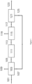
- This arrangement is shown in Figure 1 .
- the total energy input is -316MW LHV.
- Carbon dioxide is emitted to the atmosphere from the hydrogen plant at a rate of 64.7 tes/hr.
- the baseline Carbon intensity of the existing hydrogen plant with natural gas feed and fuel (scope 1 emissions) is therefore 9.06kgs COz/kg H 2 .
- the SMR-based hydrogen plant shown in Figure 1 is to be integrated with a renewable diesel (RND) hydrotreated processing a mix of vegetable oils, tallow and waste cooking oil to make 600,000 tes/yr RND (on stream factor 0.9)
- RND renewable diesel
- the approximate performance metrics of the new RND hydrotreater are as follows:
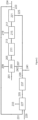
- FIG. 2 shows a block schematic of the new hydrotreater with the existing hydrogen plant.
- the hydrogen plant supplies hydrogen make-up (231) to the RNG hydrotreater, while off-gas is used on the existing hydrogen plant (242) , displacing all the natural gas fuel to the SMR (and leaving some off-gas fuel for use elsewhere on the refinery).
- Table 1 gives the stream flows and conditions.
- the emission of CO 2 from the hydrogen plant is 65.3 tes/hr of which -17% is biogenic, ie emissions of fossil-based COz is ⁇ 54 tes/hr. Compared to the hydrogen plant before the change this is a small reduction of 10.7 tes/hr (-17%).
- the Carbon intensity of the hydrogen plant (scope 1 emissions) is therefore 7.58kgs COz/kg H 2 (a reduction of ⁇ 1.5kgs COz/kg Hz over the base-line).
- the reduction of the carbon footprint of the renewable diesel product is ⁇ 0.04 x 1.5 - 0.06kgs COz/kg diesel or - 1g COz/MJ LHV.
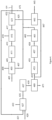
- FIG 3 shows a block schematic of the new hydrotreater and the hydrogen plant revamped with a tail-gas treatment Unit (TTU).
- TTU tail-gas treatment Unit
- the tail-gas feed is passed through a CO2 absorber to capture the CO2 content before being fed to the TTU autothermal reformer.
- the off-gas continues to be used as fuel in the Hydrogen plant SMR with the rest of the fuel being Hz product from the TTU.
- the SMR hydrogen plant supplies hydrogen make-up to the RNG hydrotreater.
- Table 2 gives the stream flows and conditions.
- the Carbon intensity of the hydrogen plant (scope 1 emissions) is therefore 0.57kgs COz/kg H 2 (a reduction of ⁇ 8.5kgs COz/kg Hz over the base-line).
- the reduction of the carbon footprint of the renewable diesel product is ⁇ 0.04 x 8.5 - 0.34kgs COz/kg diesel or - 8g COz/MJ LHV.
- FIG. 4 shows an example of a conversion of the existing SMR Hydrogen plant with a TTU and integration according to the invention with the RND hydrotreater. This example is configured for minimum natural gas input and maximum reduction of Hz product carbon intensity.
- the flows are as per Example 2 except that:
- Table 3 details key flows and conditions.
- the emission of COz from the revamped plant is -1.0 tes/hr of which 40% is biogenic, ie emissions of fossil-based COz is ⁇ 0.6 tes/hr. Compared to the hydrogen plant before its revamp this is a reduction of ⁇ 64.2 tes/hr (99%). There is also biogenic carbon capture of ⁇ 15.9 tes/hr
- the Carbon intensity of the hydrogen plant (scope 1 emissions) is therefore ⁇ -2.2kgs COz/kg H 2 (a reduction of ⁇ 11.3kgs COz/kg H 2 over the base-line).
- the reduction of the carbon footprint of the renewable diesel product is -0.04 x 11.3 - 0.45kgs COz/kg diesel or - 10g COz/MJ LHV
- Example 4 ( Figure 5 ) has a similar configuration to Example 3 ( Figure 4 ) Except that the TTU capacity is increased by feeding natural gas to it (as well as tail-gas and off-gas) in order to restore the export hydrogen capacity (net of hydrogen feed to the RND hydrotreater) to 80kNm3/hr.
- H 2 product from the TTU solely supplies the SMR reformer fuel duty.
- Both the tail-gas feed and off-gas feed are passed through absorbers to capture their COz content before being fed together with natural gas to the TTU autothermal reformer.
- Table 4 details key flows and conditions: It can be seen from the table that the net hydrogen export (streams 567+524) is ⁇ 80kNm3/hr, after providing a flow to the hydrotreater of ⁇ 33.8kNm3/hr.
- the total produced hydrogen from the revamped hydrogen plant is 113.6kNm3/hr, about 142% of the pre-retrofit rate.
- the emission of COz from the revamped plant is ⁇ 1.3 tes/hr of which 20% is biogenic, ie emissions of fossil-based COz is -1.1 tes/hr. Compared to the hydrogen plant before its revamp this is a reduction of -63.6 tes/hr (98.3%). There is also biogenic carbon capture of ⁇ 15.9 tes/hr
- the Carbon intensity of the hydrogen plant (scope 1 emissions) is therefore ⁇ -1.5kgs COz/kg H 2 (a reduction of ⁇ 10.6kgs COz/kg H 2 over the base-line).
- the reduction of the carbon footprint of the renewable diesel product is -0.04 x 10.6 - 0.42kgs COz/kg diesel or - 10g COz/MJ LHV.
- Example 5 The arrangement of Example 4 ( Figure 5 ) produces two hydrogen export streams; one of high purity (steam 524) and one of fuel quality (stream 567).
- Example 5 has a similar configuration to Example 4 except that the fuel quality stream is compressed and routed to the PSA unit on the existing Hydrogen plant, so that the full 80kNm3/hr hydrogen export from the PSA (net of feed to RND hydrotreater) is of 99.9% quality.
- Table 5 details key flows and conditions.
- the total produced hydrogen from the revamped hydrogen plant is 113.6kNm3/hr, about 142% of the pre-retrofit rate.
- the emission of COz from the revamped plant is -1.3 tes/hr of which 20% is biogenic, ie emissions of fossil-based COz is -1.1 tes/hr. Compared to the hydrogen plant before its revamp this is a reduction of -63.6 tes/hr (98.3%). There is also biogenic carbon capture of ⁇ 15.9 tes/hr
- the Carbon intensity of the hydrogen plant (scope 1 emissions) is therefore ⁇ -1.5kgs COz/kg H 2 (a reduction of ⁇ 10.6kgs COz/kg H 2 over the base-line).
- the reduction of the carbon footprint of the renewable diesel product is -0.04 x 10.6 - 0.42kgs COz/kg diesel or - 10g COz/MJ LHV. Table 1.
Landscapes
- Chemical & Material Sciences (AREA)
- Chemical Kinetics & Catalysis (AREA)
- Organic Chemistry (AREA)
- Engineering & Computer Science (AREA)
- Combustion & Propulsion (AREA)
- Inorganic Chemistry (AREA)
- Health & Medical Sciences (AREA)
- General Health & Medical Sciences (AREA)
- Oil, Petroleum & Natural Gas (AREA)
- General Chemical & Material Sciences (AREA)
- Hydrogen, Water And Hydrids (AREA)
Abstract
Description
- The present invention relates to a method for reducing the carbon dioxide emissions of a hydrotreatment plant.
- Hydrotreating is a term used to refer to the catalytic treatment of a feedstock in the presence of hydrogen as part of processes to remove materials such as sulfur, nitrogen, olefins and aromatics. Hydrotreatment is often carried out on petroleum fractions as the first step of a wider refinery process. A review of hydrotreating is provided in Handbook of Petroleum Processing pp321-354 - Chapter 8 "Hydrotreating" by A. Gruia.
- A hydrotreater is often a component of a refinery with hydrogen for the hydrotreater generated in a H2 production unit elsewhere on the refinery. A hydrocarbon-containing by-product stream generated by the refinery is sometimes treated in a H2 production unit to generate hydrogen for the hydrotreater.
-
WO2009/151690A2 describes a process involving treatment of a renewable feedstock by hydrogenating, deoxygenating, isomerizing and selectively hydrocracking the renewable feedstock in the presence of hydrogen and a catalyst to produce a reaction effluent. The reaction effluent is treated by separating the water, carbon oxides, light hydrocarbon gasses and hydrogen to generate a stream comprising paraffinic hydrocarbons, which is then separated into a hydrocarbon product comprising hydrocarbons having boiling points in the aviation fuel range, an overhead stream comprising naphtha, and a bottoms stream. In a preferred arrangement, certain components of the reaction effluent are separated and conducted to a steam reforming zone to produce hydrogen which is used in the hydrotreatment. -
WO2021/180805A1 describes a process involving passing a feedstock originating from a renewable source through a hydroprocessing stage for producing a main hydrotreated stream. The main hydrotreated stream is separated into an aqueous stream, a hydrogen-rich stream and an off-gas stream comprising hydrocarbons. The hydrogen-rich stream is recycled to the hydroprocessing stage. The off-gas stream is passed to a hydrogen producing unit where it is used to produce a make-up hydrogen stream for the hydroprocessing stage. - While it is known to transfer off-gases from the hydrotreater to a steam reforming section to generate additional hydrogen for the hydrotreatment, these steam reforming sections typically contribute significantly to the COz emissions of the refinery, as they are typically fuelled by burning a hydrocarbon fuel to provide the necessary heat for the steam reforming reactions taking place.
- There is a need for an integrated process for producing hydrogen and carrying out hydrotreatment, with lower COz emissions. The present invention addresses this need.
- In a first aspect the invention relates to a method for retrofitting a chemical plant according to
claim 1. The method involves installing a tail-gas treatment unit comprising: an autothermal reformer (ATR) or a partial oxidation (POX) reactor; a second water-gas shift (WGS) section; and a first COz removal unit. The term "second" used in connection with the "second water-gas shift section" and "first" used in connection with the "COz removal unit" are simply to differentiate these sections and units from WGS sections and COz removal units which may be present elsewhere, as will be explained in further sections. - The tail-gas treatment unit (TTU) is fed at least in part by the tail-gas stream produced by the hydrogen purification unit within the main reforming section and generates a crude H2 product stream. At least a portion of the crude H2 product stream is used as fuel in the fired reformer. A portion of the crude H2 product stream may also be used as fuel for fired heaters to heat process streams elsewhere on the plant.
- The TTU can be designed for any capacity within a wide range as long as it takes as feed, as a minimum, the tail-gas from the existing hydrogen plant. Furthermore, the constituent tail-gas treatment process units can be over-sized in design, in order to future-proof the tail-gas treatment unit for future expansions in H2 production. By replacing or eliminating hydrocarbon fuel for firing the fired reformer by generating Hz in the TTU, COz emissions from the fired reformer are greatly reduced.
- A benefit of introducing a TTU is that it does not require modification of the main reforming section, by which we mean the section formed by the fired reformer, first water-gas shift section, first water separation unit and hydrogen purification unit. The main reforming section may be operated uninterrupted right up until the change-over, when the tail-gas produced by the hydrogen purification unit is diverted to provide feed for the TTU. Furthermore, if there is limited space available adjacent to the existing hydrogen plant then the TTU can be cited remotely with pipelines running between the units.
- Operation, post retrofit, is flexible and hydrogen plant operation need not be dependent on contemporaneous operation of the hydrotreater as the existing hydrogen plant can revert to its former mode of operation with natural gas fuel (with the tail-gas treatment unit still operating without any off-gas as feed) if economics and carbon dioxide emission constraints permit this on a temporary basis.
- The method is particularly applicable to a scenario where the operator of a hydrotreatment facility wishes to change the feed from a non-biogenic feed (pre-retrofit) to a biogenic feed (post-retrofit). If the hydrotreater uses a biogenic fuel then combustion of off-gas from the hydrotreater as fuel in the SMR does not contribute to net COz emissions. However, biogenic feeds typically require significantly more H2 for hydrotreatment compared to non-biogenic fuels and therefore require the steam reforming section to operate with a higher throughput to produce the larger amounts of Hz required for the hydrotreater. Installation of a TTU according to the present invention allows the necessary additional H2 to be produced without increasing COz emissions.
- In a second aspect the invention relates to an integrated hydrogen and hydrotreatment plant according to claim 7. The plant may be produced by the retrofit method, or alternatively may be a grassroots plant.
- In a third aspect the invention relates to an integrated process for producing hydrogen and carrying out hydrotreatment according to claim 8.
-
-
Figure 1 illustrates a H2 plant without COz abatement measures. A hydrocarbon feedstock stream (101) is fed to a fired reformer (103) to produce a first reformed gas stream (105). The fired reformer is heated by combusting a fuel stream (107) on a shell side of the fired reformer to produce a flue gas stream (109). The reformed gas stream is fed to a first water-gas shift section (111) to produce a first shifted gas stream (113). The shifted gas stream is cooled to condense water, which is separated in a first water separation unit (115) to produce a first dewatered shifted gas stream (117) and a first water condensate stream (119). The first dewatered shifted gas stream is fed to a hydrogen purification unit (121) to produce a H2 product stream (123) and a tail-gas stream (125). In this example the fuel stream is provided entirely by the tail-gas stream. -
Figure 2 illustrates a H2 plant integrated with a hydrotreating section (Example 1). The hydrotreating section (227) is fed by a hydrotreatment feedstock stream (229) and a hydrotreatment H2 stream (231). The hydrotreating section produces a hydrotreatment product stream (233) and off-gas stream (235). The off-gas stream is fed to a desulfurization unit (237) to produce a desulfurized off-gas stream (239). A portion of the desulfurized off-gas stream (239) may be separated via stream (241) and a residual desulfurized off-gas stream (242). In this example the fuel stream (207) is provided by combining the residual desulfurized off-gas stream and the tail-gas stream (225). The H2 product stream (223) is split into a hydrotreatment H2 stream (231) and a second H2 product stream (224). -
Figure 3 illustrates a H2 plant integrated with a hydrotreating section (Example 2). This arrangement is based on the arrangement shown in Example 2. The tail-gas stream (325) is fed to a second carbon dioxide separation unit (343) to produce a second carbon dioxide-containing stream (345) and a purified tail-gas stream (347). The purified tail-gas stream is combined with a make-up hydrocarbon stream (349) to provide the tail-gas feedstock stream (351). The tail-gas feedstock stream is fed to an autothermal reformer (353) together with an oxygen-containing stream (not shown) to produce a second reformed gas stream (355). The second reformed gas stream is fed to a second water-gas shift section (357) to produce a second shifted gas stream (359). The second shifted gas stream, optionally having been dewatered, is fed to a first carbon dioxide separation unit (361) to produce a first carbon dioxide-containing stream (363) and a crude H2 product stream (365). A portion of the crude H2 product stream may be separated as a second H2 stream (367). -
Figure 4 illustrates a H2 plant integrated with a hydrotreating section (Example 3). This arrangement is based on the arrangement shown in Example 2. Instead of using the desulfurized off-gas stream (439) to produce the fuel stream (407), the desulfurized off-gas stream is first purified in a third carbon dioxide separation unit (469) to produce a third carbon dioxide-containing stream (471) and a purified off-gas stream (473). The purified off-gas stream and purified tail-gas stream (447) are combined to produce the tail-gas feedstock stream (451). A portion of the Hz product stream (423) is separated via stream (475) and combined with the crude Hz stream (465) to produce the fuel stream (407). -
Figure 5 illustrates a H2 plant integrated with a hydrotreating section (Example 4). This arrangement is based on the arrangement shown in Example 3. The tail-gas feedstock stream (551) is produced by combining the purified off-gas stream (573), the purified tail-gas stream (547) and make-up hydrocarbon stream (549). The crude H2 stream (565) is produced in an amount which is in excess of what is required to provide the fuel duty for the fired reformer (503). The crude Hz stream is split into a fuel stream (507) which is used in the fired reformer, and a second H2 stream (567) which may be used for heating duty elsewhere on the plant. -
Figure 6 illustrates a H2 plant integrated with a hydrotreatment section (Example 5). This arrangement is based on the arrangement shown in Example 4. Instead of using the second fuel stream (667) elsewhere on the plant, the second fuel stream is compressed in compressor (669) to produce a compressed second fuel stream (671) which is returned upstream of the hydrogen purification unit (621). - Any sub-headings are for convenience only and are not intended to limit the invention.
- Any aspect or embodiment described as being preferred in connection with the retrofit method also applies to the plant and method of the invention, and vice versa.
- References herein to the "main reforming section" refer to the section comprising the fired reformer, first water-gas shift section, first water separation unit and hydrogen purification unit. It will be appreciated that intermediate stages of heating or cooling process streams may be present in between these stages. The role of the main reforming section is to generate a Hz product stream (typically ≥ 99 vol% H2). At least a portion of the H2 product stream is used to provide the H2 needed by the hydrotreating section. The hydrogen purification unit also produces a tail-gas stream which used to generate the tail-gas feedstock stream described below.
- A fired reformer, also known as a steam methane reformer or SMR, typically comprises one or more tubes containing a steam reforming catalyst. The tubes are fed with a hydrocarbon feedstock stream which contains hydrocarbons (with methane being the predominant component) and steam. Heat for the endothermic steam reforming reactions taking place in the tubes ("tube side") is provided by combusting a fuel stream on the shell side of the reformer to produce a flue gas stream. In many existing hydrogen plants the fuel stream is predominantly hydrocarbon based and, unless the flue gas stream is treated to remove carbon dioxide, results in the emission of COz. The fired reformer produces a first reformed gas stream. Here "first" is used simply to differentiate from the second reformed gas stream produced in the TTU. In the present invention the fuel stream is provided at least in part by the crude H2 stream.
- The first reformed gas stream is typically cooled before being fed to the first WGS section. The first WGS section includes one or more WGS shift stages and may include stages of high-temperature shift, medium-temperature shift, isothermal shift and low-temperature shift. These terms, as well as suitable catalysts therefore, are described in
WO2022/003312A1 . - The stream exiting the WGS unit is referred to as a first shifted gas stream and ideally comprises COz, H2, with the residual being steam, small amounts of unreacted methane and CO and inert gases.
- The first shifted gas stream is cooled to a temperature below the dew point so that the steam condenses to water. Any suitable technique may be used and such techniques for water removal are described in
WO2022/003312A1 . - The role of the hydrogen purification is to separate the first dewatered shifted gas stream into a H2 product stream and a tail-gas stream. Any suitable purification unit may be used, but a preferred unit is a pressure swing adsorption (PSA) unit. The H2 product stream typically and preferably has a purity of ≥ 99 vol% H2. At least a portion of the H2 product stream is used to provide the H2 needed by the hydrotreating section.
- The role of the hydrotreating section is to carry out hydrotreatment on a hydrotreatment feedstock stream and produce a hydrotreated stream and an off-gas stream.
- The hydrotreating section includes a hydrotreater and may also include additional units such as for dewaxing, isomerisation and hydrocracking. The H2 for each of these additional units is preferably provided by a portion of the product H2 stream. In addition to off-gases produced by the hydrotreater, off-gas streams may be produced from the additional units (including streams with low commercial value, such as those comprising C3-C5 hydrocarbons from a hydrocracker). These off-gas streams, optionally after having undergone treatment, may also be used to produce the tail-gas feedstock stream. Examples of treatment include purification to remove impurities such as sulfur compounds, or pre-reforming.
- While the off-gas stream will have a lower sulfur content as compared to the hydrotreatment feedstock stream, in all embodiments of the invention it is preferred that the off-gas stream from the hydrotreater is first desulfurized to produce a desulfurized off-gas stream. Embodiments referring to the off-gas stream also apply to the desulfurized off-gas stream.
- If the off-gas stream contains significant amounts of COz then it may be desirable to treat the off-gas stream in a third carbon dioxide separation unit, upstream of the TTU, which is arranged to accept the off-gas stream and produce a third carbon dioxide-containing stream and a purified off-gas stream. Here, "third" is used to differentiate the carbon dioxide separation unit and the carbon dioxide-containing stream from the first and second carbon dioxide separation units and carbon dioxide-containing streams described in other sections. The purified off-gas stream may be used to produce the tail-gas feedstock stream. The retrofit method may therefore comprise installing a third carbon dioxide separation unit upstream of the TTU, the third carbon dioxide separation unit being arranged to accept the off-gas stream and produce a third carbon dioxide-containing stream and a purified off-gas stream. Removing carbon dioxide upstream of the TTU has the benefit of reducing the throughput through the TTU and may avoid having to oversize the TTU.
- In a preferred embodiment the hydrotreatment feedstock stream is biogenic, i.e. it is derived from renewable sources rather than fossil fuel sources. If the hydrotreatment feedstock stream is biogenic then the off-gas may be used to provide the fuel gas without contribution to net COz emissions.
- The TTU comprises, sequentially: an autothermal reformer (ATR) or partial oxidation reactor (POX), a second water-gas shift section, and a first carbon dioxide separation unit. Additional units (e.g. heat exchangers, steam removal etc...) may also be present in the TTU.
- The feed to the ATR or POX is referred to herein as the tail-gas feedstock stream. The tail-gas feedstock stream includes at least a portion of the tail-gas stream from the hydrogen purification unit, preferably all of the tail-gas stream. In this way the fuel stream to the fired reformer makes use of the crude Hz stream produced by the TTU rather than combusting the tail-gas stream, thereby lowering the COz content of the flue gas stream produced by the fired reformer.
- In some embodiments the tail-gas stream from the hydrogen purification unit may be used as the tail-gas feedstock stream directly, i.e. without altering its chemical composition. Because the tail-gas stream may still contain significant amounts of COz, in a preferred embodiment the tail-gas stream is treated in a second carbon dioxide separation unit upstream of the TTU to produce a second carbon dioxide-containing stream and a purified tail-gas stream. Here, "second" is used to differentiate the carbon dioxide separation unit and the carbon dioxide-containing stream from the first and third carbon dioxide separation units and carbon dioxide-containing streams described in other sections. The retrofit method may therefore comprise installing a second carbon dioxide separation unit upstream of the TTU, the third carbon dioxide separation unit being arranged to accept the tail-gas stream and produce a second carbon dioxide-containing stream and a purified tail-gas stream. Removing carbon dioxide upstream of the TTU has the benefit of reducing the throughput through the TTU and may avoid having to oversize the TTU.
- In a preferred embodiment the tail-gas stream is supplemented with at least a portion of the off-gas stream from the hydrotreating section to produce the tail-gas feedstock stream. The retrofit method may therefore comprise installing means for feeding at least a portion of the off-gas stream to produce the tail-gas feedstock stream. In preferred embodiments all of the off-gas stream from the hydrotreating section is used to produce the tail-gas feedstock stream. Passing some, preferably all of the tail-gas stream through the TTU is desirable if the goal is to minimise the COz content of the flue gas stream.
- The role of the ATR or POX is to convert hydrocarbons in the tail-gas feedstock stream into hydrogen and carbon oxides through steam reforming reactions. The steam content of the tail-gas feedstock steam may be adjusted by steam addition prior to entering the ATR or POX reactor.
- The skilled person will be familiar with the design of autothermal reformers and detail of their arrangement and suitable catalysts are summarised in
WO2022/003312A1 . An ATR generally comprises a burner disposed at the top of the reformer, to which the hydrocarbon-containing fuel stream and an oxygen-containing gas are fed, a combustion zone beneath the burner through which a flame extends, and a fixed bed of particulate steam reforming catalyst disposed below the combustion zone. In autothermal reforming, the heat for the endothermic steam reforming reactions is therefore provided by combustion of a portion of hydrocarbon in the hydrocarbon-containing fuel stream. The hydrocarbon-containing fuel stream is typically fed to the top of the reformer and the oxygen-containing gas fed to the burner, mixing and combustion occur downstream of the burner generating a heated gas mixture the composition of which is brought to equilibrium as it passes through the steam reforming catalyst. - Partial oxidation reactors are known and typically comprise a vessel to which the feed and an oxygen-containing gas are fed via a burner, analogous to that used in an autothermal reformer, disposed above a reaction chamber in which the partial combustion reactions take place. Unlike an autothermal reformer, a catalyst is not present in the vessel. Air, oxygen-enriched air or O2 may be used as the oxygen-containing gas. The combustion temperature may be about 1300°C, or higher. Steam may be added to the feed and/or the oxygen containing gas to lower the combustion temperature and reduce soot formation. The idealised formula for this reaction applied to methane in the feed is as follows:
2 CH4 + O2 → 2CO + 4 Hz
- However, yields are below stoichiometric because part of the feed is fully combusted. It is therefore preferred that the TTU comprises an ATR.
- The stream exiting the POX or ATR is referred to herein as a second reformed gas stream.
- In one embodiment the TTU comprises a gas-heated reformer (GHR) in addition to the ATR or POX reactor. The skilled person will be familiar with the design of gas-heated reformers and detail of their arrangement and suitable catalysts are described for instance in
WO2022/003312A1 ,GB1578270A WO97/05947A1 US4910228A . In general a GHR comprises one or more catalyst-filled tubes (defining a tube side), and is arranged so that hot gas passes over the outer surface of the tubes (a shell side) providing heat for the endothermic steam reforming reactions taking place tube side. In this arrangement hot gases from the outlet of the ATR or POX reactor are used as the hot gas on the shell-side of the GHR. The GHR and ATR or POX reactor can be arranged in any suitable arrangement, typically GHR followed by ATR or POX reactor with the hot gases then being sent to the GHR shell-side, although other arrangements are possible. - It is generally preferred that the TTU does not include any reforming stage other than the ATR or POX reactor.
- The second reformed gas stream is typically cooled before being fed to the second WGS section. The second WGS section includes one or more WGS shift stages and may include stages of high-temperature shift, medium-temperature shift, isothermal shift and low-temperature shift. These terms, as well as suitable catalysts therefore, are described in
WO2022/003312A1 . - The stream exiting the WGS unit is referred to as a second shifted gas stream and ideally comprises COz, H2, with the residual being small amounts of methane and CO and inert gases.
- It is preferred that steam or water removal is carried out on the second shifted gas stream before it is sent to the first carbon dioxide separation unit. Typically the second shifted gas stream is cooled to a temperature below the dew point so that the steam condenses. Suitable techniques for water removal are described in
WO2022/003312A1 . - The role of the first COz removal unit is to separate the second shifted gas stream into a first carbon dioxide-containing stream and a crude Hz stream. Any suitable COz separation technology may be used and the skilled person will be aware of suitable technologies. Examples include physical wash systems, reactive wash systems (e.g. an amine wash system) and cryogenic systems.
- In some cases the carbon dioxide-containing stream produced by the first, second and/or third COz removal units may be a relatively pure stream of COz gas (e.g. where the COz removal unit operates by cryogenic separation). However, "carbon dioxide-containing stream" should be understood in a broad sense. Preferred COz removal units operate by means of a wash system, for example an amine wash, and produce a CO2-laden adsorbent; the term "carbon dioxide-containing stream" should be understood to encompass such laden sorbent streams. The first, second and third carbon-dioxide containing streams may be processed separately to produce relatively pure carbon dioxide streams. Alternatively, one or more of these carbon-dioxide containing streams may be combined before being processed. Regenerated adsorbent is then returned to the COz removal units.
- The crude H2 stream is used, at least in part, to provide the fuel stream for the fired reformer.
- In some embodiments the TTU may produce the crude H2 stream in an amount in excess of what is required to fuel the fired reformer. In this case the crude Hz stream is split into a fuel stream, which is fed to the fired reformer, and a second H2 stream. The second H2 stream may be used for heating duty elsewhere on the plant, e.g. by being combusted in fired heaters to heat process streams elsewhere on the plant. If it is desired to maximise the amount of the Hz product stream, then some or all of the second H2 stream may be compressed and returned upstream of the hydrogen purification unit; typically downstream from the first water removal unit. The retrofit method may therefore comprise installing means to split the crude H2 stream into a fuel stream which is fed to the fired reformer and a second Hz stream, a compressor which is arranged to compress the second H2 stream to produce a compressed second Hz stream, and means for returning the compressed second H2 steam upstream of the hydrogen purification unit.
- In some embodiments the fuel stream is provided by the off-gas stream and the crude H2 stream. This may be particularly acceptable when the hydrotreatment feedstock stream is biogenic and therefore combustion of the off-gas stream does not contribute to net COz emissions.
- In some embodiments the fuel stream is provided entirely by the crude H2 stream. It will be appreciated that the amount of tail-gas feedstock stream fed to the TTU will need to be controlled in order to produce a sufficient amount of crude H2 stream to fuel the fired reformer. This may be achieved by supplementing the tail-gas stream with one or more of the off-gas stream and/or a make-up hydrocarbon stream e.g. a natural gas stream.
- A refinery has an SMR-based Hydrogen plant producing ~80kNm3/hr hydrogen. The existing hydrogen plant currently utilises 20,984 kgs/hr (1164.5 kgmols/hr) natural gas as feedstock and 3,466 kgs/hr (192.3 kgmols/hr) as fuel to the SMR (additional to PSA tail-gas fuel). This arrangement is shown in
Figure 1 . The total energy input is -316MW LHV. Carbon dioxide is emitted to the atmosphere from the hydrogen plant at a rate of 64.7 tes/hr. The baseline Carbon intensity of the existing hydrogen plant with natural gas feed and fuel (scope 1 emissions) is therefore 9.06kgs COz/kg H2. - The SMR-based hydrogen plant shown in
Figure 1 is to be integrated with a renewable diesel (RND) hydrotreated processing a mix of vegetable oils, tallow and waste cooking oil to make 600,000 tes/yr RND (on stream factor 0.9) The approximate performance metrics of the new RND hydrotreater are as follows: - RND LHV -44 MJ/kg
- Feedstock oils fed at 1.207 kgs/kg RND
- H2 feed at 0.040 kgs/kg RND
- Co-produced streams are available at low pressure - when aggregated these provide COz at 0.045 kgs/kg RND, propane at 0.055 kgs/kg and hydrogen at 0.004 kgs/kg RND.
- The contribution of the hydrogen usage to the carbon footprint of the renewable diesel product is ~0.04 x 9.06 - 0.4 kgs COz/kg diesel or - 9g COz/MJ LHV (second order scope 2 and scope 3 emissions for H2 production will increase this slightly).
-
Figure 2 shows a block schematic of the new hydrotreater with the existing hydrogen plant. The hydrogen plant supplies hydrogen make-up (231) to the RNG hydrotreater, while off-gas is used on the existing hydrogen plant (242) , displacing all the natural gas fuel to the SMR (and leaving some off-gas fuel for use elsewhere on the refinery). Table 1 gives the stream flows and conditions. - It can be seen from the table that the net hydrogen export (stream 224) is ~46kNm3/hr, after providing a flow to the hydrotreater of ~33.8kNm3/hr.
- The emission of CO2 from the hydrogen plant is 65.3 tes/hr of which -17% is biogenic, ie emissions of fossil-based COz is ~54 tes/hr. Compared to the hydrogen plant before the change this is a small reduction of 10.7 tes/hr (-17%).
- The Carbon intensity of the hydrogen plant (
scope 1 emissions) is therefore 7.58kgs COz/kg H2 (a reduction of ~1.5kgs COz/kg Hz over the base-line). The reduction of the carbon footprint of the renewable diesel product is ~0.04 x 1.5 - 0.06kgs COz/kg diesel or - 1g COz/MJ LHV. -
Figure 3 shows a block schematic of the new hydrotreater and the hydrogen plant revamped with a tail-gas treatment Unit (TTU). In this example there is no integration between the RND hydrotreater and the SMR/TTU units. The tail-gas feed is passed through a CO2 absorber to capture the CO2 content before being fed to the TTU autothermal reformer. The off-gas continues to be used as fuel in the Hydrogen plant SMR with the rest of the fuel being Hz product from the TTU. The SMR hydrogen plant supplies hydrogen make-up to the RNG hydrotreater. Table 2 gives the stream flows and conditions. - It can be seen from the table that the net hydrogen export (
streams 367 and 324) is still ~65kNm3/hr, after providing a flow to the hydrotreater of ~33.8kNm3/hr. The total produced hydrogen from the revamped hydrogen plant is 98.6kNm3/hr, an increase of ~23% over the pre-retrofit rate. - The emission of COz from the revamped plant is 16.4 tes/hr of which 97% is biogenic, ie emissions of fossil-based COz is -0.5 tes/hr. Compared to the hydrogen plant before its revamp this is a huge reduction of -64.2 tes/hr (99.2%).
- The Carbon intensity of the hydrogen plant (
scope 1 emissions) is therefore 0.57kgs COz/kg H2 (a reduction of ~8.5kgs COz/kg Hz over the base-line). The reduction of the carbon footprint of the renewable diesel product is ~0.04 x 8.5 - 0.34kgs COz/kg diesel or - 8g COz/MJ LHV. -
Figure 4 shows an example of a conversion of the existing SMR Hydrogen plant with a TTU and integration according to the invention with the RND hydrotreater. This example is configured for minimum natural gas input and maximum reduction of Hz product carbon intensity. The flows are as per Example 2 except that: - i) The only natural gas feed is to the SMR.
- ii) Instead of routing off-gas to SMR fuel, it is fed to the TTU. It passes first to a COz separation column; the decarbonised off-gas is fed together with decarbonised tail-gas to an oxygen-fired ATR in the TTU.
- iii) All the TTU product is used as fuel in the SMR with a small balancing flow taken from the hydrogen produced by the SMR unit.
- Table 3 details key flows and conditions.
- It can be seen from the table that the net hydrogen export (stream 424) is ~44kNm3/hr, after providing a flow to the hydrotreater of ~33.8kNm3/hr. The total produced hydrogen from the revamped hydrogen plant is 77.8kNm3/hr, about 97% of the pre-retrofit rate.
- The emission of COz from the revamped plant is -1.0 tes/hr of which 40% is biogenic, ie emissions of fossil-based COz is ~0.6 tes/hr. Compared to the hydrogen plant before its revamp this is a reduction of ~64.2 tes/hr (99%). There is also biogenic carbon capture of ~15.9 tes/hr
- The Carbon intensity of the hydrogen plant (
scope 1 emissions) is therefore ~ -2.2kgs COz/kg H2 (a reduction of ~11.3kgs COz/kg H2 over the base-line). The reduction of the carbon footprint of the renewable diesel product is -0.04 x 11.3 - 0.45kgs COz/kg diesel or - 10g COz/MJ LHV - Example 4 (
Figure 5 ) has a similar configuration to Example 3 (Figure 4 ) Except that the TTU capacity is increased by feeding natural gas to it (as well as tail-gas and off-gas) in order to restore the export hydrogen capacity (net of hydrogen feed to the RND hydrotreater) to 80kNm3/hr. - Now H2 product from the TTU solely supplies the SMR reformer fuel duty. Both the tail-gas feed and off-gas feed are passed through absorbers to capture their COz content before being fed together with natural gas to the TTU autothermal reformer. Table 4 details key flows and conditions:
It can be seen from the table that the net hydrogen export (streams 567+524) is ~80kNm3/hr, after providing a flow to the hydrotreater of ~33.8kNm3/hr. The total produced hydrogen from the revamped hydrogen plant is 113.6kNm3/hr, about 142% of the pre-retrofit rate. - The emission of COz from the revamped plant is ~1.3 tes/hr of which 20% is biogenic, ie emissions of fossil-based COz is -1.1 tes/hr. Compared to the hydrogen plant before its revamp this is a reduction of -63.6 tes/hr (98.3%). There is also biogenic carbon capture of ~15.9 tes/hr
- The Carbon intensity of the hydrogen plant (
scope 1 emissions) is therefore ~ -1.5kgs COz/kg H2 (a reduction of ~10.6kgs COz/kg H2 over the base-line). The reduction of the carbon footprint of the renewable diesel product is -0.04 x 10.6 - 0.42kgs COz/kg diesel or - 10g COz/MJ LHV. - The arrangement of Example 4 (
Figure 5 ) produces two hydrogen export streams; one of high purity (steam 524) and one of fuel quality (stream 567). Example 5 has a similar configuration to Example 4 except that the fuel quality stream is compressed and routed to the PSA unit on the existing Hydrogen plant, so that the full 80kNm3/hr hydrogen export from the PSA (net of feed to RND hydrotreater) is of 99.9% quality. Table 5 details key flows and conditions. - This requires a modest increase in impurities adsorbed in the PSA (about 5%). The total produced hydrogen from the revamped hydrogen plant is 113.6kNm3/hr, about 142% of the pre-retrofit rate.
- The emission of COz from the revamped plant is -1.3 tes/hr of which 20% is biogenic, ie emissions of fossil-based COz is -1.1 tes/hr. Compared to the hydrogen plant before its revamp this is a reduction of -63.6 tes/hr (98.3%). There is also biogenic carbon capture of ~15.9 tes/hr
- The Carbon intensity of the hydrogen plant (
scope 1 emissions) is therefore ~ -1.5kgs COz/kg H2 (a reduction of ~10.6kgs COz/kg H2 over the base-line). The reduction of the carbon footprint of the renewable diesel product is -0.04 x 10.6 - 0.42kgs COz/kg diesel or - 10g COz/MJ LHV.Table 1. Stream 201 209 223 224 225 229 231 233 239 241 242 Temperature (°C) 40.0 175 40.0 40.0 33.0 40.0 40.0 40.0 40.0 Pressure (bara) 42.0 0.02 25.0 25.0 1.30 40.0 1.30 1.30 1.30 Mass flow (kg/h) 20985 202684 7139 4126 48528 91891 3013 76103 7880 2301 5579 Molar flow (kgmol/hr) 1164 6856 3569 2062 1685 1507 314 92 222 Component (mol%) H2O 17.0 0.75 H2 100 100 23.7 100 45.2 45.2 45.2 CO 14.5 CO2 2.00 21.7 50.9 24.8 24.8 24.8 N2 0.90 59.5 0.62 Ar 0.76 CH4 89.0 9.45 C2H6 7.00 C3H8 1.00 30.0 30.0 30.0 C4H10 0.10 O2 1.05 Table 2. Stream 301 309 323 324 325 329 331 333 339 347 349 363 365 367 Temperature (°C) 40.0 175 40.0 40.0 33.0 40.0 40.0 40.0 40.0 30.0 40.0 40.0 Pressure (bara) 42.0 0.02 25.0 25.0 1.30 40.0 1.30 30.1 42.0 36.0 10.0 20.0 Mass flow (kg/h) 20985 157162 7139 4126 48528 91891 3013 76103 7880 10720 5166 68280 5309 2517 Molar flow (kgmol/hr) 1164 5985 3569 2062 1685 1507 314 818 286 1557 1811 859 Component (mol%) H2O 24.2 0.75 0.30 0.38 0.38 H2 99.9 99.9 23.7 99.9 45.2 48.7 0.34 96.7 96.7 CO 14.5 29.9 0.04 0.76 0.76 CO2 2.00 6.24 50.9 24.8 0.52 2.00 99.4 0.19 0.19 N2 0.89 67.4 0.62 1.27 0.89 0.89 0.89 Ar 0.99 0.81 0.81 CH4 89.0 9.45 19.4 89.0 0.06 0.25 0.25 C2H6 7.00 7.00 C3H8 1.00 30.0 1.00 C4H10 0.10 0.10 O2 1.18 Table 3. Stream 401 409 423 424 425 429 431 433 451 463 475 Temperature (°C) 40.0 175 40.0 40.0 33.0 40.0 40.0 30.0 40.0 Pressure (bara) 42.0 0.02 25.0 25.0 1.30 40.0 30.1 36.0 1.30 Mass flow (kg/h) 20985 138368 7139 3927 48528 91891 3013 76103 10720 70468 199 Molar flow (kgmol/hr) 1164 5681 3569 1962 1685 1507 818 1607 99.9 Component (mol%) H2O 32.3 0.75 0.30 H2 99.9 99.9 23.7 99.9 48.7 0.34 99.9 CO 14.5 29.9 0.04 CO2 2.00 0.38 50.9 0.52 99.5 N2 0.89 65.1 0.62 1.27 Ar 1.06 CH4 89.0 9.45 19.36 0.03 C2H6 7.00 C3H8 1.00 C4H10 0.10 O2 Table 4. Stream 501 507 509 523 524 525 529 531 533 547 549 563 565 567 Temperature (°C) 40.0 40.0 175 40.0 40.0 33.0 40.0 40.0 40.0 30.0 40.0 40.0 Pressure (bara) 42.0 1.30 0.02 25.0 25.0 1.30 40.0 30.1 42.0 36.0 20.0 20.0 Mass flow (kg/h) 20985 5393 140085 7139 4126 48528 91891 3013 76103 10720 10869 98468 9768 4375 Molar flow (kgmol/hr) 1164 1903 5753 3569 2062 1685 1507 818 603 2246 3446 1543 Component (mol%) H2O 0.38 32.4 0.75 0.30 0.38 0.38 H2 97.2 99.9 99.9 23.7 99.9 48.7 0.34 97.2 97.2 CO 0.51 14.5 29.9 0.04 0.51 0.51 CO2 2.00 0.19 0.34 50.9 0.52 2.00 99.54 0.19 0.19 Nz 0.89 0.66 65.0 0.62 1.27 0.89 0.66 0.66 Ar 0.92 1.13 0.92 0.92 CH4 89.0 0.18 9.45 19.4 89.0 0.03 0.18 0.18 C2H6 7.00 7.00 C3H8 1.00 1.00 C4H10 0.10 0.10 O2 1.14 Table 5. Stream 601 607 609 623 624 625 629 631 633 647 649 663 665 671 Temperature (°C) 40.0 40.0 175 40.0 40.0 33.0 40.0 40.0 40.0 30.0 40.0 40.0 Pressure (bara) 42.0 1.30 0.02 25.0 25.0 1.30 40.0 30.1 42.0 36.0 20.0 26.0 Mass flow (kg/h) 20985 6245 141956 10137 7124 51135 91891 3013 76103 13064 10901 99143 11876 5631 Molar flow (kgmol/hr) 1164 1927 5807 5068 3561 1922 1507 1045 605 2261 3666 1739 Component (mol%) H2O 0.36 32.1 0.99 0.29 0.36 0.36 H2 95.9 99.9 99.9 29.4 99.9 54.0 0.34 95.6 95.9 CO 0.50 13.2 24.2 0.04 0.50 0.50 CO2 2.00 0.18 0.51 44.8 0.41 2.00 99.5 0.18 0.18 N2 0.89 1.17 64.9 1.60 2.93 0.89 1.17 1.17 Ar 1.65 1.37 1.49 2.72 1.65 1.65 CH4 89.0 0.18 8.45 15.4 89.0 0.03 0.18 0.18 C2H6 7.00 7.00 C3H8 1.00 1.00 C4H10 0.10 0.10 O2 1.14
Claims (15)
- A method for retrofitting a chemical plant which initially comprises:(a) a hydrotreating section which is arranged to accept a hydrotreatment feedstock stream and produce a hydrotreated stream and an off-gas stream;(b) a steam reforming section comprising:(b-i) a fired reformer which is arranged to accept a hydrocarbon feedstock stream and produce a first reformed gas stream, the fired reformer heated by combusting a fuel stream on a shell side of the fired reformer to produce a flue gas stream;(b-ii) a first water-gas shift section which is arranged to accept the first reformed gas stream and produce a first shifted gas stream;(b-iii) a first water separation unit which is arranged to accept the first shifted gas stream and produce a first dewatered shifted gas stream and a first water stream;(b-iv) a hydrogen purification unit which is arranged to accept the first dewatered shifted gas stream and produce a H2 product stream and a tail-gas stream;the method comprising the step of installing:(c) a tail-gas treatment unit comprising:(c-i) an autothermal reformer or a partial oxidation reactor which is arranged to accept a tail-gas feedstock stream comprising at least part of the tail-gas stream and produce a second reformed gas stream(c-ii) a second water-gas shift section which is arranged to accept the second reformed gas stream and produce a second shifted gas stream;(c-iii) a first carbon dioxide separation unit which is arranged to accept the second shifted gas stream and produce a crude Hz stream and a first carbon dioxide-containing stream;wherein the tail-gas treatment unit is arranged to be fed at least in part with the tail-gas stream; andwherein the fuel stream is provided at least in part by the crude H2 stream.
- A retrofit method according to claim 1, wherein the method comprises installing a second carbon dioxide separation unit upstream of the tail-gas treatment unit which is arranged to accept the tail-gas stream and produce a second carbon dioxide-containing stream and a purified tail-gas stream.
- A retrofit method according to claim 1 or claim 2, wherein the method comprises installing means for feeding at least a portion of the off-gas stream to produce the tail-gas feedstock stream.
- A retrofit method according to any of claims 1 to 3, wherein the method comprises installing a third carbon dioxide separation unit upstream of the tail-gas treatment unit which is arranged to accept the off-gas stream and produce a third carbon dioxide-containing stream and a purified off-gas stream.
- A retrofit method according to any of claims 1 to 4, wherein the method comprises installing means to split the crude Hz stream into a fuel stream which is fed to the fired reformer and a second H2 stream, a compressor which is arranged to compress the second H2 stream to produce a compressed crude H2 stream and means for returning the compressed crude H2 steam upstream of the hydrogen purification unit.
- A retrofit method according to claim 5, wherein the method comprises installing means for heating one or more process streams in one or more fired heaters by combusting at least a portion of the crude H2 stream.
- An integrated hydrogen and hydrotreatment plant comprising:(a) a hydrotreating section which is arranged to accept a hydrotreatment feedstock stream and produce a hydrotreated stream and an off-gas stream;(b) a steam reforming section comprising:(b-i) a fired reformer which is arranged to accept a hydrocarbon feedstock stream and produce a first reformed gas stream, the fired reformer heated by combusting a fuel stream on a shell side of the fired reformer to produce a flue gas stream;(b-ii) a first water-gas shift section which is arranged to accept the first reformed gas stream and produce a first shifted gas stream;(b-iii) a first water separation unit which is arranged to accept the first shifted gas stream and produce a first dewatered shifted gas stream and a first water stream;(b-iv) a hydrogen purification unit which is arranged to accept the first dewatered shifted gas stream and produce a H2 product stream and a tail-gas stream;(c) a tail-gas treatment unit comprising:(c-i) an autothermal reformer or a partial oxidation reactor which is arranged to accept a tail-gas feedstock stream comprising at least part of the tail-gas stream and produce a second reformed gas stream(c-ii) a second water-gas shift section which is arranged to accept the second reformed gas stream and produce a second shifted gas stream;(c-iii) a carbon dioxide separation unit which is arranged to accept the second shifted gas stream and produce a crude H2 stream and a first carbon dioxide-containing stream;wherein the tail-gas treatment unit is arranged to be fed at least in part with the tail-gas stream; andwherein the fuel stream is provided at least in part by the crude H2 stream.
- An integrated process for producing hydrogen and carrying out hydrotreatment, comprising the steps of:(a) carrying out hydrotreatment of a hydrotreatment feedstock stream in a hydrotreating section to produce a hydrotreated stream and an off-gas stream;(b) carrying out steam reforming in a steam reforming section comprising:(b-i) a fired reformer which is arranged to accept a hydrocarbon feedstock stream and produce a first reformed gas stream, the fired reformer heated by combusting a fuel stream on a shell side of the fired reformer to produce a flue gas stream;(b-ii) a first water-gas shift section which is arranged to accept the first reformed gas stream and produce a first shifted gas stream;(b-iii) a first water separation unit which is arranged to accept the first shifted gas stream and produce a dewatered shifted gas stream and a first water stream;(b-iv) a hydrogen purification unit which is arranged to accept the first dewatered shifted gas stream and produce a H2 product stream and a tail-gas stream;(c) feeding a tail-gas feedstock stream comprising at least part of the tail-gas stream to a tail-gas treatment unit comprising:(c-i) an autothermal reformer or a partial oxidation reactor which is arranged to accept the tail-gas feedstock stream and produce a second reformed gas stream;(c-ii) a second water-gas shift section which is arranged to accept the second reformed gas stream and produce a second shifted gas stream;(c-iii) a carbon dioxide separation unit which is arranged to accept the second shifted gas stream and produce a crude H2 stream and a first carbon dioxide-containing stream;wherein the fuel stream is provided at least in part by the crude H2 stream;wherein the H2 product stream provides the H2 for the hydrotreatment.
- A process according to claim 8, wherein the fuel stream is provided entirely by the crude H2 stream.
- A process according to claim 8, wherein the fuel stream is provided by the off-gas stream and the crude H2 stream.
- A process according to any of claims 8 to 10, wherein the tail-gas feedstock stream is provided by the tail-gas stream and a make-up hydrocarbon stream.
- A process according to any of claims 8 to 10, wherein the tail-gas feedstock stream is provided by the tail-gas stream and the off-gas stream.
- A process according to any of claims 8 to 10, wherein the tail-gas feedstock stream is provided by the tail-gas stream, the off-gas stream, and a make-up hydrocarbon stream.
- A process according to any of claims 8 to 13, wherein a portion of the crude H2 product stream is used as fuel for fired heaters to heat process streams elsewhere on the plant.
- A process according to any of claims 8 to 14, wherein the hydrotreatment feedstock stream is biogenic.
Priority Applications (5)
| Application Number | Priority Date | Filing Date | Title |
|---|---|---|---|
| EP23169857.2A EP4455076B1 (en) | 2023-04-25 | 2023-04-25 | Decarbonisation of a hydrotreatment plant |
| PL23169857.2T PL4455076T3 (en) | 2023-04-25 | 2023-04-25 | Decarbonisation of a hydrotreatment plant |
| HRP20260413TT HRP20260413T1 (en) | 2023-04-25 | 2023-04-25 | Decarbonisation of a hydrotreatment plant |
| ES23169857T ES3064767T3 (en) | 2023-04-25 | 2023-04-25 | Decarbonisation of a hydrotreatment plant |
| PCT/GB2024/051068 WO2024224062A1 (en) | 2023-04-25 | 2024-04-24 | Decarbonisation of a hydrotreatment plant |
Applications Claiming Priority (1)
| Application Number | Priority Date | Filing Date | Title |
|---|---|---|---|
| EP23169857.2A EP4455076B1 (en) | 2023-04-25 | 2023-04-25 | Decarbonisation of a hydrotreatment plant |
Publications (3)
| Publication Number | Publication Date |
|---|---|
| EP4455076A1 true EP4455076A1 (en) | 2024-10-30 |
| EP4455076B1 EP4455076B1 (en) | 2026-02-11 |
| EP4455076C0 EP4455076C0 (en) | 2026-02-11 |
Family
ID=86226494
Family Applications (1)
| Application Number | Title | Priority Date | Filing Date |
|---|---|---|---|
| EP23169857.2A Active EP4455076B1 (en) | 2023-04-25 | 2023-04-25 | Decarbonisation of a hydrotreatment plant |
Country Status (5)
| Country | Link |
|---|---|
| EP (1) | EP4455076B1 (en) |
| ES (1) | ES3064767T3 (en) |
| HR (1) | HRP20260413T1 (en) |
| PL (1) | PL4455076T3 (en) |
| WO (1) | WO2024224062A1 (en) |
Citations (9)
| Publication number | Priority date | Publication date | Assignee | Title |
|---|---|---|---|---|
| GB1578270A (en) | 1977-04-04 | 1980-11-05 | Pullman Inc | Heat exchange apparatus |
| US4910228A (en) | 1988-02-18 | 1990-03-20 | Imperial Chemical Industries Plc | Methanol |
| WO1997005947A1 (en) | 1995-08-07 | 1997-02-20 | Imperial Chemical Industries Plc | Heat exchange apparatus and process |
| US20090298957A1 (en) * | 2004-11-16 | 2009-12-03 | Pierre-Robert Gauthier | Method and installation for combined production of hydrogen and carbon dioxide |
| WO2009151690A2 (en) | 2008-03-17 | 2009-12-17 | Uop Llc | Production of aviation fuel from renewable feedstocks |
| CN101285004B (en) * | 2007-04-11 | 2010-12-15 | 中国科学院工程热物理研究所 | A multifunctional energy device |
| CN107557075B (en) * | 2017-10-23 | 2019-11-08 | 武汉凯迪工程技术研究总院有限公司 | Biomass indirect liquefaction synthetic oil technique and its system |
| WO2021180805A1 (en) | 2020-03-13 | 2021-09-16 | Haldor Topsøe A/S | Process and plant for producing hydrocarbons with reduced co2-footprint and improved hydrogen integration |
| WO2022003312A1 (en) | 2020-06-30 | 2022-01-06 | Johnson Matthey Public Limited Company | Process for producing hydrogen |
Family Cites Families (1)
| Publication number | Priority date | Publication date | Assignee | Title |
|---|---|---|---|---|
| US11772966B2 (en) | 2021-03-29 | 2023-10-03 | Uop Llc | Integrated hydrogen production and bio-renewable conversion process |
-
2023
- 2023-04-25 HR HRP20260413TT patent/HRP20260413T1/en unknown
- 2023-04-25 ES ES23169857T patent/ES3064767T3/en active Active
- 2023-04-25 EP EP23169857.2A patent/EP4455076B1/en active Active
- 2023-04-25 PL PL23169857.2T patent/PL4455076T3/en unknown
-
2024
- 2024-04-24 WO PCT/GB2024/051068 patent/WO2024224062A1/en not_active Ceased
Patent Citations (9)
| Publication number | Priority date | Publication date | Assignee | Title |
|---|---|---|---|---|
| GB1578270A (en) | 1977-04-04 | 1980-11-05 | Pullman Inc | Heat exchange apparatus |
| US4910228A (en) | 1988-02-18 | 1990-03-20 | Imperial Chemical Industries Plc | Methanol |
| WO1997005947A1 (en) | 1995-08-07 | 1997-02-20 | Imperial Chemical Industries Plc | Heat exchange apparatus and process |
| US20090298957A1 (en) * | 2004-11-16 | 2009-12-03 | Pierre-Robert Gauthier | Method and installation for combined production of hydrogen and carbon dioxide |
| CN101285004B (en) * | 2007-04-11 | 2010-12-15 | 中国科学院工程热物理研究所 | A multifunctional energy device |
| WO2009151690A2 (en) | 2008-03-17 | 2009-12-17 | Uop Llc | Production of aviation fuel from renewable feedstocks |
| CN107557075B (en) * | 2017-10-23 | 2019-11-08 | 武汉凯迪工程技术研究总院有限公司 | Biomass indirect liquefaction synthetic oil technique and its system |
| WO2021180805A1 (en) | 2020-03-13 | 2021-09-16 | Haldor Topsøe A/S | Process and plant for producing hydrocarbons with reduced co2-footprint and improved hydrogen integration |
| WO2022003312A1 (en) | 2020-06-30 | 2022-01-06 | Johnson Matthey Public Limited Company | Process for producing hydrogen |
Non-Patent Citations (1)
| Title |
|---|
| A. GRUIA: "Handbook of Petroleum Processing", pages: 321 - 354 |
Also Published As
| Publication number | Publication date |
|---|---|
| EP4455076B1 (en) | 2026-02-11 |
| HRP20260413T1 (en) | 2026-05-08 |
| PL4455076T3 (en) | 2026-04-27 |
| ES3064767T3 (en) | 2026-04-28 |
| EP4455076C0 (en) | 2026-02-11 |
| WO2024224062A1 (en) | 2024-10-31 |
Similar Documents
| Publication | Publication Date | Title |
|---|---|---|
| CN116133982B (en) | Low-carbon hydrogen fuel | |
| RU2516527C2 (en) | Systems and methods of producing superpure hydrogen under high pressure | |
| EP4380893B1 (en) | Method for hydrogen production coupled with co2 capture | |
| KR20230029615A (en) | How to produce hydrogen | |
| US9365466B2 (en) | Method and system for producing a liquid hydrocarbon product from a Fischer-Tropsch process using a synthesis gas produced from an oxygen transport membrane based reforming reactor | |
| RU2437830C2 (en) | Method of producing synthetic gas | |
| CN105820036B (en) | Method and system for producing methanol using partial oxidation | |
| KR20070050071A (en) | Process for producing hydrogen and / or carbon monoxide | |
| EP2944606A1 (en) | Process for generating hydrogen from a fischer-tropsch off-gas | |
| GB2625645A (en) | Process for producing hydrogen | |
| JP2020508951A (en) | Enhanced waste heat recovery using pre-reformers in combination with oxygen and fuel preheating for combustion | |
| KR20250128296A (en) | Process for producing hydrogen | |
| US9216396B2 (en) | Non-catalytic recuperative reformer | |
| EP4455076B1 (en) | Decarbonisation of a hydrotreatment plant | |
| US20250034458A1 (en) | Integration of steam cracker and blue ammonia units to reduce co2 emission | |
| CN120826385A (en) | Method for synthesizing methanol | |
| KR20250155008A (en) | Method for producing blue ammonia | |
| JP7680538B2 (en) | Method for minimizing nitrogen oxide emissions from a steam reforming plant and steam reforming plant | |
| EP4530251A1 (en) | Decarbonisation of a chemical plant | |
| EA046288B1 (en) | LOW CARBON HYDROGEN FUEL | |
| WO2026093123A1 (en) | Plant and process for producing a synthesis gas with low carbon intensity (ci) | |
| CN121794218A (en) | A method for synthesizing methanol with optimized syngas preparation and processing. | |
| TW202502646A (en) | Plant and process for producing hydrogen from hydrocarbons with reduced co emissions | |
| KR20240169640A (en) | Process for retrofitting a simultaneous methanol and ammonia production plant |
Legal Events
| Date | Code | Title | Description |
|---|---|---|---|
| REG | Reference to a national code |
Ref country code: HR Ref legal event code: TUEP Ref document number: P20260413T Country of ref document: HR |
|
| PUAI | Public reference made under article 153(3) epc to a published international application that has entered the european phase |
Free format text: ORIGINAL CODE: 0009012 |
|
| STAA | Information on the status of an ep patent application or granted ep patent |
Free format text: STATUS: THE APPLICATION HAS BEEN PUBLISHED |
|
| AK | Designated contracting states |
Kind code of ref document: A1 Designated state(s): AL AT BE BG CH CY CZ DE DK EE ES FI FR GB GR HR HU IE IS IT LI LT LU LV MC ME MK MT NL NO PL PT RO RS SE SI SK SM TR |
|
| RAP3 | Party data changed (applicant data changed or rights of an application transferred) |
Owner name: JOHNSON MATTHEY PUBLIC LIMITED COMPANY |
|
| STAA | Information on the status of an ep patent application or granted ep patent |
Free format text: STATUS: REQUEST FOR EXAMINATION WAS MADE |
|
| 17P | Request for examination filed |
Effective date: 20250425 |
|
| GRAP | Despatch of communication of intention to grant a patent |
Free format text: ORIGINAL CODE: EPIDOSNIGR1 |
|
| STAA | Information on the status of an ep patent application or granted ep patent |
Free format text: STATUS: GRANT OF PATENT IS INTENDED |
|
| INTG | Intention to grant announced |
Effective date: 20250908 |
|
| RAP1 | Party data changed (applicant data changed or rights of an application transferred) |
Owner name: JOHNSON MATTHEY DAVY TECHNOLOGIES LIMITED |
|
| GRAS | Grant fee paid |
Free format text: ORIGINAL CODE: EPIDOSNIGR3 |
|
| GRAA | (expected) grant |
Free format text: ORIGINAL CODE: 0009210 |
|
| STAA | Information on the status of an ep patent application or granted ep patent |
Free format text: STATUS: THE PATENT HAS BEEN GRANTED |
|
| AK | Designated contracting states |
Kind code of ref document: B1 Designated state(s): AL AT BE BG CH CY CZ DE DK EE ES FI FR GB GR HR HU IE IS IT LI LT LU LV MC ME MK MT NL NO PL PT RO RS SE SI SK SM TR |
|
| REG | Reference to a national code |
Ref country code: CH Ref legal event code: F10 Free format text: ST27 STATUS EVENT CODE: U-0-0-F10-F00 (AS PROVIDED BY THE NATIONAL OFFICE) Effective date: 20260211 Ref country code: GB Ref legal event code: FG4D |
|
| REG | Reference to a national code |
Ref country code: DE Ref legal event code: R096 Ref document number: 602023011759 Country of ref document: DE |
|
| REG | Reference to a national code |
Ref country code: IE Ref legal event code: FG4D |
|
| REG | Reference to a national code |
Ref country code: GR Ref legal event code: EP Ref document number: 20260400627 Country of ref document: GR Effective date: 20260407 |
|
| PGFP | Annual fee paid to national office [announced via postgrant information from national office to epo] |
Ref country code: NO Payment date: 20260320 Year of fee payment: 4 |
|
| U01 | Request for unitary effect filed |
Effective date: 20260309 |
|
| U07 | Unitary effect registered |
Designated state(s): AT BE BG DE DK EE FI FR IT LT LU LV MT NL PT RO SE SI Effective date: 20260313 |
|
| PGFP | Annual fee paid to national office [announced via postgrant information from national office to epo] |
Ref country code: GR Payment date: 20260320 Year of fee payment: 4 |
|
| REG | Reference to a national code |
Ref country code: HR Ref legal event code: ODRP Ref document number: P20260413T Country of ref document: HR Payment date: 20260407 Year of fee payment: 4 |
|
| REG | Reference to a national code |
Ref country code: ES Ref legal event code: FG2A Ref document number: 3064767 Country of ref document: ES Kind code of ref document: T3 Effective date: 20260428 |
|
| U20 | Renewal fee for the european patent with unitary effect paid |
Year of fee payment: 4 Effective date: 20260319 |
|
| REG | Reference to a national code |
Ref country code: HR Ref legal event code: T1PR Ref document number: P20260413 Country of ref document: HR |
|
| PGFP | Annual fee paid to national office [announced via postgrant information from national office to epo] |
Ref country code: HU Payment date: 20260427 Year of fee payment: 4 |
|
| REG | Reference to a national code |
Ref country code: HU Ref legal event code: AG4A Ref document number: E075751 Country of ref document: HU |
|
| PG25 | Lapsed in a contracting state [announced via postgrant information from national office to epo] |
Ref country code: RS Free format text: LAPSE BECAUSE OF FAILURE TO SUBMIT A TRANSLATION OF THE DESCRIPTION OR TO PAY THE FEE WITHIN THE PRESCRIBED TIME-LIMIT Effective date: 20260511 |
|
| PGFP | Annual fee paid to national office [announced via postgrant information from national office to epo] |
Ref country code: ES Payment date: 20260504 Year of fee payment: 4 |
|
| PGFP | Annual fee paid to national office [announced via postgrant information from national office to epo] |
Ref country code: PL Payment date: 20260331 Year of fee payment: 4 |
|
| PGFP | Annual fee paid to national office [announced via postgrant information from national office to epo] |
Ref country code: HR Payment date: 20260407 Year of fee payment: 4 |
|
| PG25 | Lapsed in a contracting state [announced via postgrant information from national office to epo] |
Ref country code: IS Free format text: LAPSE BECAUSE OF FAILURE TO SUBMIT A TRANSLATION OF THE DESCRIPTION OR TO PAY THE FEE WITHIN THE PRESCRIBED TIME-LIMIT Effective date: 20260611 |