EP4455025A1 - Capping apparatus for a packaging machine and packaging machine having a capping apparatus - Google Patents
Capping apparatus for a packaging machine and packaging machine having a capping apparatus Download PDFInfo
- Publication number
- EP4455025A1 EP4455025A1 EP24165801.2A EP24165801A EP4455025A1 EP 4455025 A1 EP4455025 A1 EP 4455025A1 EP 24165801 A EP24165801 A EP 24165801A EP 4455025 A1 EP4455025 A1 EP 4455025A1
- Authority
- EP
- European Patent Office
- Prior art keywords
- station
- packages
- mounting
- carrier
- conveying device
- Prior art date
- Legal status (The legal status is an assumption and is not a legal conclusion. Google has not performed a legal analysis and makes no representation as to the accuracy of the status listed.)
- Pending
Links
Images



Classifications
-
- B—PERFORMING OPERATIONS; TRANSPORTING
- B65—CONVEYING; PACKING; STORING; HANDLING THIN OR FILAMENTARY MATERIAL
- B65B—MACHINES, APPARATUS OR DEVICES FOR, OR METHODS OF, PACKAGING ARTICLES OR MATERIALS; UNPACKING
- B65B7/00—Closing containers or receptacles after filling
- B65B7/16—Closing semi-rigid or rigid containers or receptacles not deformed by, or not taking-up shape of, contents, e.g. boxes or cartons
-
- B—PERFORMING OPERATIONS; TRANSPORTING
- B65—CONVEYING; PACKING; STORING; HANDLING THIN OR FILAMENTARY MATERIAL
- B65B—MACHINES, APPARATUS OR DEVICES FOR, OR METHODS OF, PACKAGING ARTICLES OR MATERIALS; UNPACKING
- B65B61/00—Auxiliary devices, not otherwise provided for, for operating on sheets, blanks, webs, binding material, containers or packages
- B65B61/18—Auxiliary devices, not otherwise provided for, for operating on sheets, blanks, webs, binding material, containers or packages for making package-opening or unpacking elements
- B65B61/184—Auxiliary devices, not otherwise provided for, for operating on sheets, blanks, webs, binding material, containers or packages for making package-opening or unpacking elements by applying tabs over discharge openings, e.g. over discharge openings defined by tear or score lines
-
- B—PERFORMING OPERATIONS; TRANSPORTING
- B65—CONVEYING; PACKING; STORING; HANDLING THIN OR FILAMENTARY MATERIAL
- B65B—MACHINES, APPARATUS OR DEVICES FOR, OR METHODS OF, PACKAGING ARTICLES OR MATERIALS; UNPACKING
- B65B7/00—Closing containers or receptacles after filling
- B65B7/16—Closing semi-rigid or rigid containers or receptacles not deformed by, or not taking-up shape of, contents, e.g. boxes or cartons
- B65B7/28—Closing semi-rigid or rigid containers or receptacles not deformed by, or not taking-up shape of, contents, e.g. boxes or cartons by applying separate preformed closures, e.g. lids, covers
-
- B—PERFORMING OPERATIONS; TRANSPORTING
- B65—CONVEYING; PACKING; STORING; HANDLING THIN OR FILAMENTARY MATERIAL
- B65B—MACHINES, APPARATUS OR DEVICES FOR, OR METHODS OF, PACKAGING ARTICLES OR MATERIALS; UNPACKING
- B65B7/00—Closing containers or receptacles after filling
- B65B7/16—Closing semi-rigid or rigid containers or receptacles not deformed by, or not taking-up shape of, contents, e.g. boxes or cartons
- B65B7/28—Closing semi-rigid or rigid containers or receptacles not deformed by, or not taking-up shape of, contents, e.g. boxes or cartons by applying separate preformed closures, e.g. lids, covers
- B65B7/2821—Closing semi-rigid or rigid containers or receptacles not deformed by, or not taking-up shape of, contents, e.g. boxes or cartons by applying separate preformed closures, e.g. lids, covers applying plugs or threadless stoppers
-
- B—PERFORMING OPERATIONS; TRANSPORTING
- B65—CONVEYING; PACKING; STORING; HANDLING THIN OR FILAMENTARY MATERIAL
- B65B—MACHINES, APPARATUS OR DEVICES FOR, OR METHODS OF, PACKAGING ARTICLES OR MATERIALS; UNPACKING
- B65B7/00—Closing containers or receptacles after filling
- B65B7/16—Closing semi-rigid or rigid containers or receptacles not deformed by, or not taking-up shape of, contents, e.g. boxes or cartons
- B65B7/28—Closing semi-rigid or rigid containers or receptacles not deformed by, or not taking-up shape of, contents, e.g. boxes or cartons by applying separate preformed closures, e.g. lids, covers
- B65B7/2842—Securing closures on containers
Definitions
- the present invention relates to a capping apparatus for applying caps onto packages filled with a pourable product, preferentially packages formed from a multilayer packaging material.
- the present invention also relates to a packaging machine for the packaging of pourable products, preferentially pourable food products, into packages, preferentially packages formed from a multilayer packaging material, and having at least one capping apparatus.
- liquid or pourable food products such as fruit juice, UHT (ultra-high-temperature treated) milk, wine, tomato sauce, etc.
- packages in particular sealed packages, made of sterilized packaging material.
- a typical example is the parallelepiped-shaped package for pourable food products known as Tetra Brik Aseptic (registered trademark), which is made by sealing and folding a laminated strip packaging material.
- the packaging material has a multilayer structure comprising a carton and/or paper base layer, covered on both sides with layers of heat-seal plastic material, e.g. polyethylene.
- the packaging material also comprises a layer of oxygen-barrier material, e.g. an aluminum foil, which is superimposed on a layer of heat-seal plastic material, and is in turn covered with another layer of heat-seal plastic material forming the inner face of the package eventually contacting the food product.
- Packages of this sort are normally produced on fully automatic packaging machines, which form and fill the packages starting from a multilayer packaging material.
- Some packaging machines are configured to produce packages comprising a main body formed from the multilayer packaging material and an opening device arranged about a pour opening of the main body.
- the opening device is configured to allow for selectively opening and closing the pouring outlet.
- a typical opening device comprises a collar arranged about the pouring outlet and a cap mounted to the collar and being controllable between a closing position and an opening position.
- a typical packaging machine for producing packages having a respective opening device comprise a package forming apparatus configured to form at least the respective main bodies from the multilayer packaging material and a capping apparatus configured to apply at least the cap to the respective package.
- the package forming apparatus may be configured to produce packages having both the respective main body formed form the multilayer packaging material and a collar arranged about the respective pouring outlet.
- the capping apparatus is configured to apply the caps onto the collar.
- the package comprises the main body and a base frame carrying a collar and the cap being mounted to the collar are glued onto the main body.
- the capping apparatus comprises a conveyor configured to advance a succession of the packages as originating from the package forming machine and having a plurality of mounting devices arranged in succession to one another.
- the capping apparatus also comprises a conveying apparatus which is configured to move the plurality of mounting devices back and forth along a path being parallel to an advancement path of the packages.
- Each mounting device is configured to apply one respective cap at a time onto one respective package and at the same time as the other mounting devices of the plurality of mounting devices apply the respective cap onto the respective package.
- each mounting device comprises a mounting head, configured to apply (in an example, screw) one respective cap onto one respective package.
- each mounting device has a mounting head different from the mounting heads of the other mounting devices.
- the mounting devices are separate and/or spaced apart from the conveying apparatus.
- EP-A-3656684 discloses another kind of capping apparatus.
- the capping apparatus comprises a planar motor having a plurality of carriers.
- the carriers receive either the caps to be mounted on the packages or the packages onto which the caps shall be mounted.
- the capping apparatus comprises a conveyor which conveys either the packages or the caps.
- the control of the carriers allows to arrange the packages and the caps adjacent to one another and to mount the respective caps to the packages. Such a solution avoids the use of mounting devices.
- Number 1 indicates as a whole a packaging machine for producing packages 2 filled with a pourable product, in particular a pourable food product, such as (pasteurized) milk, fruit juice, wine, tomato sauce, salt, sugar, emulsions, yoghurt, milk drinks etc.
- a pourable food product such as (pasteurized) milk, fruit juice, wine, tomato sauce, salt, sugar, emulsions, yoghurt, milk drinks etc.
- Packaging machine 1 may be configured to produce packages 2 filled with the pourable product.
- packaging machine 1 may be configured to produce packages 2 from a packaging material having a multilayer configuration.
- the packaging material may comprise at least one layer of fibrous material, such as e.g. a paper or cardboard, and at least two layers of heat-seal plastic material, e.g. polyethylene, interposing the layer of fibrous material in between one another.
- a layer of fibrous material such as e.g. a paper or cardboard
- heat-seal plastic material e.g. polyethylene
- the packaging material may also comprise a layer of gas- and light-barrier material, e.g. aluminum foil or ethylene vinyl alcohol (EVOH) film, in particular being arranged between one of the layers of the heat-seal plastic material and the layer of fibrous material.
- the packaging material may also comprise a further layer of heat-seal plastic material being interposed between the layer of gas- and light-barrier material and the layer of fibrous material.
- packaging material may be provided in the form of a web 3.
- each package 2 may comprise a respective main body 4 formed from the multilayer packaging material and an opening device 5 arranged about a pour opening of the respective main body 4.
- each pour opening may be covered by a separation membrane 6, separation membrane being preferentially formed from portions of the multilayer packaging material.
- Each opening device 5 may comprise also a cap 7 configured to selectively open and close the respective pour opening. Preferentially, each cap 7 is mounted to the respective package 2 when being delivered to an end user.
- each opening device 5 may comprise a collar 8 protruding from the respective main body 4 and being arranged about the respective pouring opening.
- each cap 7 may be mounted to the respective collar 8.
- each cap 7 may be selectively removed from the respective collar 8 so as to open the respective pour opening for allowing outflow of the pourable product from the respective package 2.
- each cap 7 may be (repeatably) moveable between a respective closing position and a respective opening position at which the respective cap 7 respectively closes and opens the respective pour opening.
- each opening device 5 may also comprise a respective coupling element 9 connected to and protruding from the respective separation membrane.
- each coupling element 9 may be also connected to, preferentially sealed to, the respective cap 7.
- the coupling element 9 follows movement of the respective cap 7 leading to a detachment of the respective separation membrane from the respective main body 4.
- each cap 7 may comprise a cutter configured to pierce the respective separation membrane.
- the cutter pierces the separation membrane.
- packaging machine 1 may comprise:
- capping apparatus 15 may be arranged downstream from package filling apparatus 14 and may be configured to receive packages 2 from package filling apparatus 14.
- capping apparatus 15 comprises:
- mounting devices 19 and/or the respective mounting stations 20 are stationary i.e. not movable.
- each mounting device 19 may comprise a mounting head configured to apply (e.g. to screw) one respective cap 7 onto each respective package 2.
- capping apparatus 15 may comprise a control unit 21 configured to control operation of capping apparatus 15 itself.
- control unit 21 may be configured to control conveying device 16 and/or mounting devices 19.
- conveying device 16 comprises a planar motor 22 having a plurality of carriers 23 configured to receive packages 2 at inlet station 17 and to discharge packages 2 at outlet station 18.
- conveying device 16 is configured to selectively advance each carrier 23 from inlet station 17 to one respective mounting station 20 such that the respective mounting device 19 mounts, in use, the respective cap 7 onto the respective package 2 carried by the respective carrier 23.
- conveying device 16 is also configured to advance each carrier 23 from the respective mounting station 20 to outlet station 18 so as to allow for discharging packages 2 at outlet station 18.
- conveying device 16 may be configured to selectively control movement of each carrier 23, preferentially independently from the other carriers 23.
- independently means that conveying device 16 may accelerate and decelerate each carrier 23 in a selective manner, which may differ from any acceleration and deceleration of other carriers 23.
- conveying device 16 may control movement of each carrier 23 such to avoid any undesired impact with the one or more other carriers 23.
- each carrier 23 may comprise a support structure for carrying the respective package 2.
- each carrier 23 may also comprise a retaining group configured to retain packages 2 on carrier 23, in particular during advancement of the respective carrier 23.
- Each retaining group may be moveable between an open configuration and a closed configuration at which the retaining group, respectively, allows to place or discharge the at least one respective package 2 and to secure the at least one respective package 2.
- each package 2 may be, in use, placed on the respective carrier 23 such that a first wall of the respective package 2 is in contact with the respective carrier 23 (preferentially, with the support structure of the respective carrier 23). Additionally, a second wall opposed from the first wall carries the respective pour opening.
- planar motor 22 may also comprise a planar control module 26, preferentially being operatively coupled to the control unit 21.
- planar control module 26 may comprise a plurality of coils configured to generate local electromagnetic fields for selectively moving carriers 23.
- carriers 23 are movable (more preferentially slidably moveable ) above planar control module 26.
- conveying device 16 preferentially planar control module 26, may be configured to control movement of each carrier 23 along a first direction D1, a second direction D2 perpendicular to first direction D1 and preferably also in a third direction perpendicular to first direction D1 and second direction D2.
- each carrier 23 and therewith also of the respective packages 2 in a two-dimensional space or, preferably, a three-dimensional space.
- movement of each carrier 23 along the third direction allows to modify a distance between carrier 23 and planar control module 26.
- movement of carriers 23 along the third direction may be obtained by magnetic levitation.
- conveying device 16 preferentially planar control module 26 may be configured to control carriers 23 along the third direction so as to elevate carriers 23 from planar control module 26. E.g., with the coils being powered off, carriers 23 are placed on planar control module 26.
- conveying device 16 preferentially planar control module 26, may be configured to control an angular position of each carrier 23 along a first rotation axis parallel to first direction D1 and/or a second rotation axis parallel to second direction D2 and/or a third rotation axis parallel to the third direction.
- planar control module 26 may be configured to control the plurality of coils in order to control movement of carriers 23, preferentially along first direction D1, second direction D2 and the third direction and around the first rotation axis, the second rotation axis and the third rotation axis.
- planar control module 26 may extend along a first axis, preferentially parallel to first direction D1, and a second axis, preferentially parallel to second direction D2.
- planar control module 26 may comprise a first end portion and a second end portion displaced from one another along first direction D1 and/or a first terminal portion and a second terminal portion displaced from one another along second direction D2.
- inlet station 17 and/or outlet station 18 may be arranged at and/or adjacent to, respectively, the first end portion and the second end portion.
- each carrier 23 may comprise at least one magnetic and/or ferromagnetic element allowing for interaction of each carrier 23 with the local electromagnetic fields generated by the coils.
- conveying device 16, preferentially planar control module 26, may be configured to selectively control movement of each carrier 23 along the first axis and first direction D1 and the second axis and second direction D2 by controlling the interaction of the local electromagnetic fields with the at least one magnetic and/or ferromagnetic element of each carrier 23.
- capping apparatus 15 may further comprise one or more cap delivery devices 27, each one configured to deliver caps 7 to at least one cap delivery station 28 at which at least one cap 7 is delivered to each package 2 advanced, preferentially by the respective carrier 23, to cap delivery station 28.
- each cap delivery device 27 may comprise a delivery track configured to deliver caps 7 to one respective cap delivery station 28.
- conveying apparatus 7 may be configured to selectively advance each carrier 23, preferentially from inlet station 17, to one respective cap delivery station 28 so that a respective cap 7 is delivered to the respective package 2.
- conveying apparatus 7 may be configured to advance carriers 23 after delivery of the respective caps 7 to the respective package 2, to the respective mounting stations 20.
- each cap delivery station 28 and mounting stations 20 may be different from one another.
- each cap delivery station 28 may correspond and/or be associated to one respective mounting station 20.
- the one or more cap delivery devices 27 may be configured to deliver the respective caps 7 onto the respective packages 2 at the respective mounting station 20 and/or may deliver the respective cap 7 to the respective mounting device 19.
- each mounting device 19 may be configured to receive the respective caps 7 from at least one respective cap delivery device 27 and to apply and mount the respective caps 7 onto the respective packages 2.
- each mounting device 19, preferentially the respective mounting head may be configured to pick at least one cap 7 at a time and to apply the respective cap 7 onto one respective package 2.
- each mounting head may be moveable between one respective cap delivery station 18 and one respective mounting station 20.
- each mounting device 19 may also comprise a respective stocking magazine configured to receive and stock caps 7.
- each package 2 when being delivered to inlet station 17 may comprise the respective coupling element 9.
- capping apparatus 15 may also be configured to seal each coupling element 9 to the respective caps 7.
- capping apparatus 15 may also comprise a plurality of sealing devices 29, each sealing device 29 being arranged at a respective sealing station 30 and being configured to seal the respective coupling element 9 to the respective cap 7.
- conveying device 16 may be configured to selectively advance each carrier 23 from the respective mounting station 20 to one respective sealing station 30 at which, in use, the respective coupling element 9 is sealed to the respective cap 7.
- the number of mounting devices 19 and the number of sealing devices 29 may equal one another.
- each mounting device 19 there is associated one respective sealing device 29; i.e. if a carrier 23 is, in use, advanced to one respective mounting device 19 after the mounting of the respective cap 7 the respective carrier 23 is advanced to the respective associated sealing device 29.
- each mounting device 19 and the respective associated sealing device 29 may be arranged such that an imaginary linear line intersecting the respective mounting station 20 and the respective sealing station 30 is (substantially) linear.
- capping apparatus 15 may further comprise one or more inspection devices arranged at respective inspection stations. Each inspection device may be configured to inspect a portion of the respective packages 2 conveyed to the respective inspection stations and to generate an information signal with regard to the inspected portion.
- each mounting device 19 may be configured to mount caps 7 onto the respective inspected portions of the respective packages 2.
- the inspected portion may be a respective collar 8 of the respective package 2 or the inspected portion may be the separation membrane.
- each mounting device 19 may be configured to mount the respective caps 7 onto the respective collars 8.
- each mounting device 19 may be configured to mount caps 7 together with the respective collar 8 and the respective base frame onto the respective package 2, preferentially the respective main body 4.
- each information signal may e.g. be indicative about a relative position of the respective collar 8 of each package 2 (i.e. packages 2 are fed to inlet station 17 having already the respective collar 8) with respect to edges of the respective package 2.
- the relative positions of collars 8 are subject to acceptable tolerances. As will be explained in further detail further below, by determining the relative positions, it is possible to control the positions of carriers 23 such to correctly align the packages 2 e.g. with the respective mounting devices 19 and/or the respective cap delivery devices 27 and/or the respective sealing devices 29 so as to obtain an optimal mounting of caps 7 on collars 8.
- conveying device 16 may be configured to control advancement of each carrier 23 in dependence of the respective information signal.
- conveying device 16 may be configured to control, by controlling advancement of the respective carriers 23, a relative position between the respective packages 2 and the respective mounting stations 20, and/or the respective sealing devices 29, preferentially when being arranged at the respective sealing stations 30 and/or the respective cap delivery devices 27, preferentially when being arranged at the respective cap delivery stations 28. More preferentially, conveying device 16 may be configured to control the relative positions such to optimize mounting of caps 7.
- conveying device 16 may be configured to selectively move carriers 23 along the third direction so as to approach or withdraw the respective packages 2 carried by the respective carriers 23 to or from the respective mounting stations 20, and/or the respective sealing devices 29, preferentially when being arranged at the respective sealing stations 30 and/or the respective cap delivery devices 27, preferentially when being arranged at the respective cap delivery stations 28.
- conveying device 16 may be configured to selectively control the relative positions between the packages 2 and the respective mounting devices 19, preferentially when being arranged at the respective mounting stations 20, and/or the respective sealing devices 29, preferentially when being arranged at the respective sealing stations 30 and/or the respective cap delivery devices 27, preferentially when being arranged at the respective cap delivery stations 28, along first direction D1 and/or second direction D2 and/or the third direction in function of the respective information signals and/or to rotate about the respective the first rotation axis and/or the respective the second rotation axis and/or the respective the third rotation axis.
- packages 2 when being delivered to inlet station 17 comprise the respective collar 8.
- each carrier 23 may be controlled by conveying device 16, preferentially planar control module 26, such that each collar 8 is aligned with respect to the respective cap delivery device 27 and/or the respective mounting device 19 and/or the respective sealing device 29.
- conveying device 16, preferentially planar control module 26 moves and positions carriers 23 under consideration of the respective information signals.
- packages 2 when being delivered to inlet station 17 comprise the respective main body 4 with the respective pour opening covered by separation membrane 6 but are void of the respective collar 8.
- the respective cap 7 needs to be applied onto the respective main body 4 together with the respective collar 8 (and the respective base frame) ; in other words, the respective opening devices 5 are applied on the respective main body 4.
- each carrier 23 may be controlled by conveying device 16, preferentially planar control module 26, such that each pouring outlet is aligned with respect to the respective mounting device 19.
- sealing devices 29 are not needed.
- mounting devices 19 may be configured to glue and/or weld the respective opening devices 4 onto the respective main bodies 5.
- conveying device 16, preferentially planar control module 26, may be configured to selectively advance each carrier 23 from inlet station 17 and towards outlet station 18 by selectively moving each carrier 23 along first direction D1 and second direction D2.
- conveying device 16, preferentially planar control module 26, may be configured to avoid movement of carriers 23 along first direction D1 and second direction D2 and/or rotation about rotation axis A and/or rotation axis B and/or rotation axis C and when being arranged at mounting station 20 and during operation of the respective mounting device 19 and/or when being arranged at the respective sealing station 30 and during operation of the respective sealing device 29 and/or when being arranged at the respective cap delivery station 28 and during delivery of the respective cap 7 to the respective package 2.
- each conveying device 16, preferentially planar control module 26, may be configured to selectively advance each carrier 23 along a respective advancement path P, preferentially from inlet station 17 to outlet station 18 and through at least one respective mounting station 20, more preferentially also through one respective cap delivery station 28 and/or one respective sealing station 30.
- each mounting station 20 may be downstream from inlet station 17 and upstream from outlet station 18 along the respective advancement path P.
- each cap delivery station 28 may be downstream from inlet station 17 and upstream from the respective mounting station 20 along the respective advancement path P.
- each sealing station 30 may be downstream from the respective mounting station 20 and upstream from outlet station 18 along the respective advancement path P.
- the plurality of mounting devices 19 may be arranged such that the respective mounting stations 20 are displaced from one another at least along second direction D2. Such a solution allows to easily parallelize operation of mounting devices 19.
- each mounting station 20 may be displaced from inlet station 17 at least along first direction D1.
- each mounting device 19 may be arranged such that portions of the respective advancement paths P are displaced from one another along second direction D2. Preferentially, the portions may be parallel to one another.
- inlet conveyor 32 and the outlet conveyor 33 may be aligned along first direction D1.
- two or more mounting devices 19 may be aligned along second direction D2, different from, preferentially transversal to, even more preferentially perpendicular to, first direction D1.
- Such an alignment allows an easy parallelization of the capping processes and coming along with a simple motion profile of carriers 23.
- the plurality of mounting devices 19 may be arranged such that mounting stations 20 may lie along a respective imaginary linear line, preferentially parallel to second direction D2.
- sealing devices 29 may be displaced from one another long second direction D2.
- the respective sealing stations 30 may be arranged along a respective imaginary linear line.
- two or more sealing devices 29 may be aligned along second direction D2.
- the respective portions of advancement paths P between the respective mounting station 20 and the respective sealing station 30 may be parallel to one another.
- mounting stations 20 may be arranged one after the other along first direction D1.
- respective sealing devices 29 may be arranged one after the other along first direction D1, and preferentially such that the plurality of sealing devices 29 are arranged after the plurality of mounting devices 19 along first direction D1. According to such a solution, the respective advancement paths P of carriers 23 would substantially equal one another.
- each mounting device 19 may be configured to exert a force onto the respective cap 7 into a direction coaxial to a center axis of the respective collar 8 thereby pressing the respective cap 7 onto collar 8, which again leads to the respective cap 7 being mounted onto the respective collar 8.
- each mounting device 19, preferentially the respective mounting head, may be configured to screw the respective caps 7 onto the respective collars 8.
- conveying device 16 may be configured to advances carriers 23 from outlet station 18 back to inlet station 17 and such that carriers 23 can newly advances packages 2.
- conveying device 16 may also comprise:
- inlet conveyor 32 may be configured to receive packages 2 from package filling apparatus 14 and to advance packages 2 to inlet station 17.
- inlet conveyor 32 may comprise one or more infeed tracks, in the specific example of Figure 2 shown one.
- each infeed track may comprise a conveyor belt for advancing packages 2.
- outlet conveyor 33 may be configured to advance packages 2 from outlet station 18 to end-of-line processing apparatuses.
- outlet conveyor 33 may comprise one or more outfeed tracks, in the example shown one.
- each outfeed track may comprise a conveyor belt for advancing packages 2.
- inlet conveyor 32 may be displaced from outlet conveyor 33 along first direction D1.
- conveying device 16, preferentially planar control module 26, may be configured to selectively advance carriers 23 in dependence of a rate of delivery of packages 2 to inlet station 17 and/or a desired rate of discharging packages 2 at the outlet station 18.
- the rate of delivery may depend on operation of package filling apparatus 14.
- the rate of delivery may determined by operation of inlet conveyor 32, which e.g. may receive packages 2 from one or more package filling apparatuses 14.
- the desired rate of discharging may depend on operation of the end-of-line processing apparatuses.
- package filling apparatus 14 may be configured to produce packages 2 and to fill packages 2 with the pourable product.
- package filling apparatus 14 may be configured to produce packages 2 by forming a tube 30 from web 3, longitudinally sealing tube 30, filling tube 30 with the pourable product and to transversally seal and cut tube 30.
- packaging machine 1 produces packages 2 filled with the pourable product.
- Operation of packaging machine 1 comprises at least the steps of:
- operation of packaging machine 1 may also comprise the step of forming packages 2, in particular executed by package filling apparatus 14.
- the steps of filling and forming of packages 2 may occur simultaneously.
- tube 30 is formed from advancing web 3, is longitudinally sealed, filled with the pourable product and transversally sealed and cut.
- the step of capping may be executed after the step of filling, in particular after the steps of filling and forming.
- operation of packaging machine 1 may also comprise a step of feeding, during which packages 2 are fed, in particular from package filling apparatus 7, to capping apparatus 15.
- each carrier 23 may also be advanced to a cap delivery station 28 and one respective cap 7 is delivered to the respective package 2.
- each carrier 23 may be directed to one respective sealing station 20 and after sealing of the respective coupling element 9 to the respective cap 7, carrier 23 is advanced to outlet station 18.
- each carrier 23 may be moved from inlet station 17 to the respective mounting station 19, preferably passing through cap delivery station 28, and afterward execution of the respective step of mounting, each carrier 23 may be advanced to outlet station 18, preferably passing through the respective sealing station 30.
- a sub-step of inspecting is executed and the step of selectively conveying is executed in dependence of the information signal resulting from the sub-step of inspecting.
- number 15' indicates an alternative embodiment of a capping apparatus according to the present invention. As capping apparatus 15' is similar to capping apparatus 15, the following description is limited to the differences between them, and using the same references, where possible, for identical or corresponding parts.
- capping apparatus 15' differs from capping apparatus 15 in that the plurality of mounting devices 19 are arranged such that a first group of mounting devices 19 are arranged one after the other along first direction D1 and a second group of mounting devices 19 are arranged one after the other along direct direction D1 and being spaced away from the first group of mounting devices 19 along second direction D2.
- the mounting devices 19 of the second group are staggered from the mounting devices 19 of the first group along first direction D1; i.e. when projecting the respective mounting stations 20 onto a line, at least one respective mounting station 20 of one respective mounting device 19 of the first group and of the second group is interposed between two mounting stations 20 of the respective mounting devices 19 of , respectively, the second group and the first group.
- the plurality of sealing devices 29 may be arranged such that a first group of sealing devices 29 are arranged one after the other along first direction D1 and a second group of sealing devices 29 are arranged one after the other along direct direction D1 and being spaced away from the first group of sealing devices 29 along second direction D2.
- number 15" indicates an alternative embodiment of a capping apparatus according to the present invention. As capping apparatus 15" is similar to capping apparatus 15, the following description is limited to the differences between them, and using the same references, where possible, for identical or corresponding parts.
- capping apparatus 15'' differs from capping apparatus 15 in that each carrier 23 is configured to carry two or more packages 2.
- conveying device 16, preferentially planar control module 26, may be configured to advance each carrier 23 to two or more respective mounting stations 20 such that each one of the respective packages 2 is arranged at one respective mounting station 20 and such to place each package 2 at a respective mounting station 20 and such that the respective mounting devices 19 can mount the respective caps 7 onto the respective packages 2.
- conveying device 16, preferentially planar control module 26, may also be configured to advance each carrier 23 to two or more respective sealing stations 30 such that each one of the respective packages 2 is arranged at one respective sealing station 30 so that the respective sealing devices 29 can sealing the respective coupling element 9 and the respective cap 7 to one another.
- capping apparatus 15 and/or of packaging machine 1 will be clear from the foregoing description.
- a further advantage resides in the possibility of executing maintenance activities on the single mounting device 19 and/or one sealing device 29 without productivity losses.
- mounting devices 19 there are at least four mounting devices 19 as such a number allows high productivity.
- carriers 23 may be configured to carry more than one package 2 at a time.
Landscapes
- Engineering & Computer Science (AREA)
- Mechanical Engineering (AREA)
- Auxiliary Devices For And Details Of Packaging Control (AREA)
Abstract
There is described a capping apparatus (15) for applying caps (7) onto packages (2) produced in a packaging machine (1) comprising a conveying device (16) having a planar motor (22) provided with a plurality of carriers (23) configured to receive respective packages (2) at an inlet station (17) and to advance the respective packages (2) to an outlet station (18) and a plurality of mounting devices (19), each one arranged at a respective mounting station (20) and configured to mount caps (7) onto the respective packages (2) conveyed to the respective mounting station (20). The conveying device (16) is configured to selectively advance each carrier (23) from the inlet station (17) to one respective mounting station (20) such that the respective mounting device (19) mounts, in use, the respective cap (7) onto the respective package (2) carried by the carrier (23). The conveying device (16) is also configured to advance each carrier (23) from the respective mounting station (20) to the outlet station (18) so as to permit discharging of the respective packages (2) at the outlet station (18).
Description
- The present invention relates to a capping apparatus for applying caps onto packages filled with a pourable product, preferentially packages formed from a multilayer packaging material.
- Advantageously, the present invention also relates to a packaging machine for the packaging of pourable products, preferentially pourable food products, into packages, preferentially packages formed from a multilayer packaging material, and having at least one capping apparatus.
- As is known, many liquid or pourable food products, such as fruit juice, UHT (ultra-high-temperature treated) milk, wine, tomato sauce, etc., are sold in packages, in particular sealed packages, made of sterilized packaging material.
- A typical example is the parallelepiped-shaped package for pourable food products known as Tetra Brik Aseptic (registered trademark), which is made by sealing and folding a laminated strip packaging material. The packaging material has a multilayer structure comprising a carton and/or paper base layer, covered on both sides with layers of heat-seal plastic material, e.g. polyethylene. In the case of aseptic packages for long-storage products, the packaging material also comprises a layer of oxygen-barrier material, e.g. an aluminum foil, which is superimposed on a layer of heat-seal plastic material, and is in turn covered with another layer of heat-seal plastic material forming the inner face of the package eventually contacting the food product.
- Packages of this sort are normally produced on fully automatic packaging machines, which form and fill the packages starting from a multilayer packaging material.
- Some packaging machines are configured to produce packages comprising a main body formed from the multilayer packaging material and an opening device arranged about a pour opening of the main body. The opening device is configured to allow for selectively opening and closing the pouring outlet.
- A typical opening device comprises a collar arranged about the pouring outlet and a cap mounted to the collar and being controllable between a closing position and an opening position.
- A typical packaging machine for producing packages having a respective opening device comprise a package forming apparatus configured to form at least the respective main bodies from the multilayer packaging material and a capping apparatus configured to apply at least the cap to the respective package.
- According to one possible embodiment, the package forming apparatus may be configured to produce packages having both the respective main body formed form the multilayer packaging material and a collar arranged about the respective pouring outlet. The capping apparatus is configured to apply the caps onto the collar.
- According to another possible solution, the package comprises the main body and a base frame carrying a collar and the cap being mounted to the collar are glued onto the main body.
- Typically, independently of the two specific solutions, the capping apparatus comprises a conveyor configured to advance a succession of the packages as originating from the package forming machine and having a plurality of mounting devices arranged in succession to one another. The capping apparatus also comprises a conveying apparatus which is configured to move the plurality of mounting devices back and forth along a path being parallel to an advancement path of the packages. Each mounting device is configured to apply one respective cap at a time onto one respective package and at the same time as the other mounting devices of the plurality of mounting devices apply the respective cap onto the respective package.
- In particular, each mounting device comprises a mounting head, configured to apply (in an example, screw) one respective cap onto one respective package. Preferably, each mounting device has a mounting head different from the mounting heads of the other mounting devices. Preferably, the mounting devices are separate and/or spaced apart from the conveying apparatus.
- In case of a malfunction of one of the mounting devices, operation of the capping apparatus as a whole must be interrupted.
-
EP-A-3656684 discloses another kind of capping apparatus. The capping apparatus comprises a planar motor having a plurality of carriers. The carriers receive either the caps to be mounted on the packages or the packages onto which the caps shall be mounted. Moreover, the capping apparatus comprises a conveyor which conveys either the packages or the caps. - The control of the carriers allows to arrange the packages and the caps adjacent to one another and to mount the respective caps to the packages. Such a solution avoids the use of mounting devices.
- Even though the known capping apparatuses operate satisfyingly well, a desire is felt in the sector to further improve the known packaging machines.
- It is therefore an object of the present invention to provide an improved capping apparatus.
- It is a further object of the present invention to provide an improved packaging machine.
- According to the present invention, there is provided a capping apparatus according to the
independent claim 1. - Preferred embodiments of the capping apparatus are claimed in the claims being directly or indirectly dependent on
claim 1. - According to the present invention, there is also provided a packaging machine according to
claim 15. - Three non-limiting embodiments of the present invention will be described by way of example with reference to the accompanying drawings, in which:
-
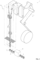
Figure 1 is a schematic view of a packaging machine having at least one capping apparatus according to the present invention, with parts removed for clarity; -
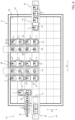
Figure 2 is a top view of a capping apparatus according to a first embodiment of the present invention, with parts removed for clarity; -
Figure 3 is a movement scheme of details of the capping apparatus ofFigure 1 , with parts removed for clarity; -
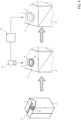
Figure 4 is a schematic view of the operation of the capping apparatus ofFigure 1 , with parts removed for clarity; -
Figure 5 is a top view of a capping apparatus according to a second embodiments of the present invention, with parts removed for clarity; and -
Figure 6 is a top view of a capping apparatus according to a third embodiments of the present invention, with parts removed for clarity. -
Number 1 indicates as a whole a packaging machine for producingpackages 2 filled with a pourable product, in particular a pourable food product, such as (pasteurized) milk, fruit juice, wine, tomato sauce, salt, sugar, emulsions, yoghurt, milk drinks etc. -
Packaging machine 1 may be configured to producepackages 2 filled with the pourable product. - In more detail,
packaging machine 1 may be configured to producepackages 2 from a packaging material having a multilayer configuration. - In further detail, the packaging material may comprise at least one layer of fibrous material, such as e.g. a paper or cardboard, and at least two layers of heat-seal plastic material, e.g. polyethylene, interposing the layer of fibrous material in between one another. One of these two layers of heat-seal plastic material may define the inner face of
package 2 contacting the pourable product. - Moreover, the packaging material may also comprise a layer of gas- and light-barrier material, e.g. aluminum foil or ethylene vinyl alcohol (EVOH) film, in particular being arranged between one of the layers of the heat-seal plastic material and the layer of fibrous material. Preferentially, the packaging material may also comprise a further layer of heat-seal plastic material being interposed between the layer of gas- and light-barrier material and the layer of fibrous material.
- In further detail, the packaging material may be provided in the form of a web 3.
- With particular reference to
Figure 4 , eachpackage 2 may comprise a respectivemain body 4 formed from the multilayer packaging material and anopening device 5 arranged about a pour opening of the respectivemain body 4. - According to some possible embodiments, each pour opening may be covered by a
separation membrane 6, separation membrane being preferentially formed from portions of the multilayer packaging material. - Each
opening device 5 may comprise also acap 7 configured to selectively open and close the respective pour opening. Preferentially, eachcap 7 is mounted to therespective package 2 when being delivered to an end user. - In further detail, each
opening device 5 may comprise acollar 8 protruding from the respectivemain body 4 and being arranged about the respective pouring opening. - Moreover, each
cap 7 may be mounted to therespective collar 8. - More specifically, each
cap 7 may be selectively removed from therespective collar 8 so as to open the respective pour opening for allowing outflow of the pourable product from therespective package 2. - Preferentially, each
cap 7 may be (repeatably) moveable between a respective closing position and a respective opening position at which therespective cap 7 respectively closes and opens the respective pour opening. - According to some possible embodiments, each
opening device 5 may also comprise arespective coupling element 9 connected to and protruding from the respective separation membrane. Preferentially, eachcoupling element 9 may be also connected to, preferentially sealed to, therespective cap 7. In particular, during a first-time control of therespective cap 7 into the respective opening position, thecoupling element 9 follows movement of therespective cap 7 leading to a detachment of the respective separation membrane from the respectivemain body 4. - Alternatively, each
cap 7 may comprise a cutter configured to pierce the respective separation membrane. In particular, during a first-time control of therespective cap 7 into the respective opening position, the cutter pierces the separation membrane. - With particular reference to
Figure 1 ,packaging machine 1 may comprise: - a
package filling apparatus 14 for fillingpackages 2, in particular for forming and fillingpackages 2, even more particular for formingpackages 2 from the multilayer packaging material and fillingpackages 2; and - at least one
capping apparatus 15 configured to at least apply onerespective cap 7 to each one ofpackages 2. - Preferentially, capping
apparatus 15 may be arranged downstream frompackage filling apparatus 14 and may be configured to receivepackages 2 frompackage filling apparatus 14. - Please note that for reasons of simplicity, in the present application, when discussing operation of capping
apparatus 15, one does not use different terms to indicatepackages 2 which still need to receive therespective caps 7 and which have therespective caps 7. - With particular reference to
Figure 2 , cappingapparatus 15 comprises: - a conveying
device 16 having at least oneinlet station 17 and at least oneoutlet station 18 and being configured to advancepackages 2 frominlet station 17 tooutlet station 18; and - a plurality of mounting
devices 19, preferentially at least four, each one arranged at a respective mountingstation 20 and configured to mountcaps 7 onto therespective packages 2 conveyed to the respective mountingstation 20. - Preferably, mounting
devices 19 and/or the respective mountingstations 20 are stationary i.e. not movable. - Preferentially, each mounting
device 19 may comprise a mounting head configured to apply (e.g. to screw) onerespective cap 7 onto eachrespective package 2. - Moreover, capping
apparatus 15 may comprise acontrol unit 21 configured to control operation of cappingapparatus 15 itself. E.g.control unit 21 may be configured to control conveyingdevice 16 and/or mountingdevices 19. - In more detail, conveying
device 16 comprises aplanar motor 22 having a plurality ofcarriers 23 configured to receivepackages 2 atinlet station 17 and to dischargepackages 2 atoutlet station 18. - With particular reference to
Figures 2 and3 , conveyingdevice 16 is configured to selectively advance eachcarrier 23 frominlet station 17 to one respective mountingstation 20 such that therespective mounting device 19 mounts, in use, therespective cap 7 onto therespective package 2 carried by therespective carrier 23. - Additionally, conveying
device 16 is also configured to advance eachcarrier 23 from the respective mountingstation 20 tooutlet station 18 so as to allow for dischargingpackages 2 atoutlet station 18. - In further detail, conveying
device 16 may be configured to selectively control movement of eachcarrier 23, preferentially independently from theother carriers 23. In this context, independently means that conveyingdevice 16 may accelerate and decelerate eachcarrier 23 in a selective manner, which may differ from any acceleration and deceleration ofother carriers 23. Furthermore, conveyingdevice 16 may control movement of eachcarrier 23 such to avoid any undesired impact with the one or moreother carriers 23. - With particular reference to
Figure 2 , eachcarrier 23 may comprise a support structure for carrying therespective package 2. - Additionally, each
carrier 23 may also comprise a retaining group configured to retainpackages 2 oncarrier 23, in particular during advancement of therespective carrier 23. Each retaining group may be moveable between an open configuration and a closed configuration at which the retaining group, respectively, allows to place or discharge the at least onerespective package 2 and to secure the at least onerespective package 2. - Preferentially, each
package 2 may be, in use, placed on therespective carrier 23 such that a first wall of therespective package 2 is in contact with the respective carrier 23 (preferentially, with the support structure of the respective carrier 23). Additionally, a second wall opposed from the first wall carries the respective pour opening. - With particular reference to
Figure 2 ,planar motor 22 may also comprise aplanar control module 26, preferentially being operatively coupled to thecontrol unit 21. - Preferentially,
planar control module 26 may comprise a plurality of coils configured to generate local electromagnetic fields for selectively movingcarriers 23. Preferentially,carriers 23 are movable (more preferentially slidably moveable ) aboveplanar control module 26. - More specifically, conveying
device 16, preferentiallyplanar control module 26, may be configured to control movement of eachcarrier 23 along a first direction D1, a second direction D2 perpendicular to first direction D1 and preferably also in a third direction perpendicular to first direction D1 and second direction D2. - In this way, it is possible to control the position of each carrier 23 (and therewith also of the respective packages 2) in a two-dimensional space or, preferably, a three-dimensional space.
- According to some preferred non-limiting embodiments, movement of each
carrier 23 along the third direction allows to modify a distance betweencarrier 23 andplanar control module 26. In particular, movement ofcarriers 23 along the third direction may be obtained by magnetic levitation. - More specifically, conveying
device 16, preferentiallyplanar control module 26, may be configured to controlcarriers 23 along the third direction so as to elevatecarriers 23 fromplanar control module 26. E.g., with the coils being powered off,carriers 23 are placed onplanar control module 26. - In addition, conveying
device 16, preferentiallyplanar control module 26, may be configured to control an angular position of eachcarrier 23 along a first rotation axis parallel to first direction D1 and/or a second rotation axis parallel to second direction D2 and/or a third rotation axis parallel to the third direction. - By providing for six-degrees of freedom, it is possible to precisely control angular and spatial positions of
packages 2. - Preferentially,
planar control module 26 may be configured to control the plurality of coils in order to control movement ofcarriers 23, preferentially along first direction D1, second direction D2 and the third direction and around the first rotation axis, the second rotation axis and the third rotation axis. - According to some preferred non-limiting embodiments,
planar control module 26 may extend along a first axis, preferentially parallel to first direction D1, and a second axis, preferentially parallel to second direction D2. - Preferentially,
planar control module 26 may comprise a first end portion and a second end portion displaced from one another along first direction D1 and/or a first terminal portion and a second terminal portion displaced from one another along second direction D2. - Advantageously,
inlet station 17 and/oroutlet station 18 may be arranged at and/or adjacent to, respectively, the first end portion and the second end portion. - Advantageously, each
carrier 23 may comprise at least one magnetic and/or ferromagnetic element allowing for interaction of eachcarrier 23 with the local electromagnetic fields generated by the coils. - More specifically, conveying
device 16, preferentiallyplanar control module 26, may be configured to selectively control movement of eachcarrier 23 along the first axis and first direction D1 and the second axis and second direction D2 by controlling the interaction of the local electromagnetic fields with the at least one magnetic and/or ferromagnetic element of eachcarrier 23. - With particular reference to
Figure 2 , cappingapparatus 15 may further comprise one or morecap delivery devices 27, each one configured to delivercaps 7 to at least onecap delivery station 28 at which at least onecap 7 is delivered to eachpackage 2 advanced, preferentially by therespective carrier 23, to capdelivery station 28. - According to some possible embodiments, each
cap delivery device 27 may comprise a delivery track configured to delivercaps 7 to one respectivecap delivery station 28. - Moreover, conveying
apparatus 7 may be configured to selectively advance eachcarrier 23, preferentially frominlet station 17, to one respectivecap delivery station 28 so that arespective cap 7 is delivered to therespective package 2. - Additionally, conveying
apparatus 7 may be configured to advancecarriers 23 after delivery of therespective caps 7 to therespective package 2, to the respective mountingstations 20. - According to the specific embodiment shown, each
cap delivery station 28 and mountingstations 20 may be different from one another. - According to some alternative embodiments, each
cap delivery station 28 may correspond and/or be associated to one respective mountingstation 20. - E.g. the one or more
cap delivery devices 27 may be configured to deliver therespective caps 7 onto therespective packages 2 at the respective mountingstation 20 and/or may deliver therespective cap 7 to therespective mounting device 19. - According to the latter embodiment, each mounting
device 19 may be configured to receive therespective caps 7 from at least one respectivecap delivery device 27 and to apply and mount therespective caps 7 onto therespective packages 2. - According to some possible embodiments, each mounting
device 19, preferentially the respective mounting head, may be configured to pick at least onecap 7 at a time and to apply therespective cap 7 onto onerespective package 2. - E.g. each mounting head may be moveable between one respective
cap delivery station 18 and one respective mountingstation 20. According to some possible variations, each mountingdevice 19 may also comprise a respective stocking magazine configured to receive andstock caps 7. - According to the specific embodiment shown, each
package 2 when being delivered toinlet station 17 may comprise therespective coupling element 9. According to such an example embodiment, cappingapparatus 15 may also be configured to seal eachcoupling element 9 to therespective caps 7. - Therefore, capping
apparatus 15 may also comprise a plurality of sealingdevices 29, each sealingdevice 29 being arranged at arespective sealing station 30 and being configured to seal therespective coupling element 9 to therespective cap 7. - Preferentially, conveying
device 16 may be configured to selectively advance eachcarrier 23 from the respective mountingstation 20 to onerespective sealing station 30 at which, in use, therespective coupling element 9 is sealed to therespective cap 7. - According to some preferred non-limiting embodiments, the number of mounting
devices 19 and the number of sealingdevices 29 may equal one another. - Preferentially, to each mounting
device 19 there is associated onerespective sealing device 29; i.e. if acarrier 23 is, in use, advanced to onerespective mounting device 19 after the mounting of therespective cap 7 therespective carrier 23 is advanced to the respective associated sealingdevice 29. - More preferentially, each mounting
device 19 and the respective associated sealingdevice 29 may be arranged such that an imaginary linear line intersecting the respective mountingstation 20 and the respective sealingstation 30 is (substantially) linear. - With reference to
Figure 4 , cappingapparatus 15 may further comprise one or more inspection devices arranged at respective inspection stations. Each inspection device may be configured to inspect a portion of therespective packages 2 conveyed to the respective inspection stations and to generate an information signal with regard to the inspected portion. - Advantageously, each mounting
device 19 may be configured to mountcaps 7 onto the respective inspected portions of therespective packages 2. - According to some examples, the inspected portion may be a
respective collar 8 of therespective package 2 or the inspected portion may be the separation membrane. - E.g., the inspection of
collar 8 may be of advantage for thesepackages 2 which comprise therespective collar 8 when being, in use, fed to therespective inlet station 17. Following such an example, each mountingdevice 19 may be configured to mount therespective caps 7 onto therespective collars 8. - On the other side, inspection of
separation membrane 6 may be of importance for these packages, which are void of any portion of therespective opening device 5 when being, in use, fed to the respective inlet station 17 (i.e. the respectivemain bodies 4 are fed to inlet station 17). According to such an example, each mountingdevice 19 may be configured to mountcaps 7 together with therespective collar 8 and the respective base frame onto therespective package 2, preferentially the respectivemain body 4. - According to some possible embodiments, each information signal may e.g. be indicative about a relative position of the
respective collar 8 of each package 2 (i.e. packages 2 are fed toinlet station 17 having already the respective collar 8) with respect to edges of therespective package 2. - One should note that the relative positions of
collars 8 are subject to acceptable tolerances. As will be explained in further detail further below, by determining the relative positions, it is possible to control the positions ofcarriers 23 such to correctly align thepackages 2 e.g. with therespective mounting devices 19 and/or the respectivecap delivery devices 27 and/or therespective sealing devices 29 so as to obtain an optimal mounting ofcaps 7 oncollars 8. - According to some preferred non-limiting embodiments, conveying
device 16 may be configured to control advancement of eachcarrier 23 in dependence of the respective information signal. - Preferentially, conveying
device 16 may be configured to control, by controlling advancement of therespective carriers 23, a relative position between therespective packages 2 and the respective mountingstations 20, and/or therespective sealing devices 29, preferentially when being arranged at the respective sealingstations 30 and/or the respectivecap delivery devices 27, preferentially when being arranged at the respectivecap delivery stations 28. More preferentially, conveyingdevice 16 may be configured to control the relative positions such to optimize mounting ofcaps 7. - In more detail, conveying
device 16 may be configured to selectively movecarriers 23 along the third direction so as to approach or withdraw therespective packages 2 carried by therespective carriers 23 to or from the respective mountingstations 20, and/or therespective sealing devices 29, preferentially when being arranged at the respective sealingstations 30 and/or the respectivecap delivery devices 27, preferentially when being arranged at the respectivecap delivery stations 28. - According to some preferred non-limiting embodiments, conveying
device 16 may be configured to selectively control the relative positions between thepackages 2 and therespective mounting devices 19, preferentially when being arranged at the respective mountingstations 20, and/or therespective sealing devices 29, preferentially when being arranged at the respective sealingstations 30 and/or the respectivecap delivery devices 27, preferentially when being arranged at the respectivecap delivery stations 28, along first direction D1 and/or second direction D2 and/or the third direction in function of the respective information signals and/or to rotate about the respective the first rotation axis and/or the respective the second rotation axis and/or the respective the third rotation axis. - According to the specific embodiment shown, packages 2 when being delivered to
inlet station 17 comprise therespective collar 8. According to such an example embodiment, eachcarrier 23 may be controlled by conveyingdevice 16, preferentiallyplanar control module 26, such that eachcollar 8 is aligned with respect to the respectivecap delivery device 27 and/or therespective mounting device 19 and/or therespective sealing device 29. In order to obtain the most appropriate alignment, conveyingdevice 16, preferentiallyplanar control module 26, moves and positionscarriers 23 under consideration of the respective information signals. - According to an alternative embodiment, packages 2 when being delivered to
inlet station 17 comprise the respectivemain body 4 with the respective pour opening covered byseparation membrane 6 but are void of therespective collar 8. According to such an embodiment, therespective cap 7 needs to be applied onto the respectivemain body 4 together with the respective collar 8 (and the respective base frame) ; in other words, therespective opening devices 5 are applied on the respectivemain body 4. According to such an embodiment, eachcarrier 23 may be controlled by conveyingdevice 16, preferentiallyplanar control module 26, such that each pouring outlet is aligned with respect to therespective mounting device 19. - Moreover, according to such an embodiment, sealing
devices 29 are not needed. In particular, mountingdevices 19 may be configured to glue and/or weld therespective opening devices 4 onto the respectivemain bodies 5. - According to some preferred non-limiting embodiments, conveying
device 16, preferentiallyplanar control module 26, may be configured to selectively advance eachcarrier 23 frominlet station 17 and towardsoutlet station 18 by selectively moving eachcarrier 23 along first direction D1 and second direction D2. - According to some preferred non-limiting embodiments, conveying
device 16, preferentiallyplanar control module 26, may be configured to avoid movement ofcarriers 23 along first direction D1 and second direction D2 and/or rotation about rotation axis A and/or rotation axis B and/or rotation axis C and when being arranged at mountingstation 20 and during operation of therespective mounting device 19 and/or when being arranged at the respective sealingstation 30 and during operation of therespective sealing device 29 and/or when being arranged at the respectivecap delivery station 28 and during delivery of therespective cap 7 to therespective package 2. - With particular reference to
Figures 2 and3 , each conveyingdevice 16, preferentiallyplanar control module 26, may be configured to selectively advance eachcarrier 23 along a respective advancement path P, preferentially frominlet station 17 tooutlet station 18 and through at least one respective mountingstation 20, more preferentially also through one respectivecap delivery station 28 and/or onerespective sealing station 30. - In further detail, each mounting
station 20 may be downstream frominlet station 17 and upstream fromoutlet station 18 along the respective advancement path P. - According to some possible embodiments, each
cap delivery station 28 may be downstream frominlet station 17 and upstream from the respective mountingstation 20 along the respective advancement path P. - According to some preferred embodiments, each sealing
station 30 may be downstream from the respective mountingstation 20 and upstream fromoutlet station 18 along the respective advancement path P. - With particular reference to
Figures 2 and3 , the plurality of mountingdevices 19 may be arranged such that the respective mountingstations 20 are displaced from one another at least along second direction D2. Such a solution allows to easily parallelize operation of mountingdevices 19. - Additionally, each mounting
station 20 may be displaced frominlet station 17 at least along first direction D1. - In other words, each mounting
device 19 may be arranged such that portions of the respective advancement paths P are displaced from one another along second direction D2. Preferentially, the portions may be parallel to one another. - According to some preferred non-limiting embodiments,
inlet conveyor 32 and theoutlet conveyor 33 may be aligned along first direction D1. - Moreover, two or
more mounting devices 19 may be aligned along second direction D2, different from, preferentially transversal to, even more preferentially perpendicular to, first direction D1. - Such an alignment allows an easy parallelization of the capping processes and coming along with a simple motion profile of
carriers 23. - According to some non-limiting embodiments, the plurality of mounting
devices 19 may be arranged such that mountingstations 20 may lie along a respective imaginary linear line, preferentially parallel to second direction D2. - According to some preferred non-limiting embodiments, in analogy to arrangement of mounting
devices 19, sealingdevices 29 may be displaced from one another long second direction D2. - E.g. the respective sealing
stations 30 may be arranged along a respective imaginary linear line. - Preferentially, two or
more sealing devices 29 may be aligned along second direction D2. - According to some preferred non-limiting embodiments, the respective portions of advancement paths P between the respective mounting
station 20 and the respective sealingstation 30 may be parallel to one another. - It should be noted that according to some possible non-limiting embodiments, mounting
stations 20 may be arranged one after the other along first direction D1. Moreover, according to such an embodiment, also therespective sealing devices 29 may be arranged one after the other along first direction D1, and preferentially such that the plurality of sealingdevices 29 are arranged after the plurality of mountingdevices 19 along first direction D1. According to such a solution, the respective advancement paths P ofcarriers 23 would substantially equal one another. - According to some possible embodiments, each mounting
device 19 may be configured to exert a force onto therespective cap 7 into a direction coaxial to a center axis of therespective collar 8 thereby pressing therespective cap 7 ontocollar 8, which again leads to therespective cap 7 being mounted onto therespective collar 8. - According to some other embodiments, each mounting
device 19, preferentially the respective mounting head, may be configured to screw therespective caps 7 onto therespective collars 8. - According to some preferred non-limiting embodiments, conveying
device 16, preferentially the respectiveplanar control module 26, may be configured toadvances carriers 23 fromoutlet station 18 back toinlet station 17 and such thatcarriers 23 can newly advances packages 2. - With particular reference to
Figure 2 , conveyingdevice 16 may also comprise: - an
inlet conveyor 32, preferentially arranged at the first end, for feedingpackages 2 toinlet station 17 at which packages 2 are transferred onto therespective carriers 23; and - an
outlet conveyor 33, preferentially arranged at the second end, for receivingpackages 2 atoutlet station 18 and is configured to receivepackages 2, in use, from therespective carriers 23. - In more detail,
inlet conveyor 32 may be configured to receivepackages 2 frompackage filling apparatus 14 and to advancepackages 2 toinlet station 17. - Advantageously,
inlet conveyor 32 may comprise one or more infeed tracks, in the specific example ofFigure 2 shown one. E.g. each infeed track may comprise a conveyor belt for advancingpackages 2. - According to some possible embodiments,
outlet conveyor 33 may be configured to advancepackages 2 fromoutlet station 18 to end-of-line processing apparatuses. - Preferentially,
outlet conveyor 33 may comprise one or more outfeed tracks, in the example shown one. E.g. each outfeed track may comprise a conveyor belt for advancingpackages 2. - According to some preferred embodiments,
inlet conveyor 32 may be displaced fromoutlet conveyor 33 along first direction D1. - According to some preferred non-limiting embodiments, conveying
device 16, preferentiallyplanar control module 26, may be configured to selectively advancecarriers 23 in dependence of a rate of delivery ofpackages 2 toinlet station 17 and/or a desired rate of dischargingpackages 2 at theoutlet station 18. - E.g. the rate of delivery may depend on operation of
package filling apparatus 14. - Preferentially, the rate of delivery may determined by operation of
inlet conveyor 32, which e.g. may receivepackages 2 from one or morepackage filling apparatuses 14. - Moreover, the desired rate of discharging may depend on operation of the end-of-line processing apparatuses.
- With particular reference to
Figure 1 ,package filling apparatus 14 may be configured to producepackages 2 and to fillpackages 2 with the pourable product. - In more detail,
package filling apparatus 14 may be configured to producepackages 2 by forming atube 30 from web 3, longitudinally sealingtube 30, fillingtube 30 with the pourable product and to transversally seal and cuttube 30. - In use,
packaging machine 1 producespackages 2 filled with the pourable product. - Operation of
packaging machine 1 comprises at least the steps of: - filling
packages 2 with the pourable product, in particular executed by ofpackage filling apparatus 14; and - capping packages 2, in particular executed by capping
apparatus 15, even more particular by the one ormore inspection units 8. - Moreover, operation of
packaging machine 1 may also comprise the step of formingpackages 2, in particular executed bypackage filling apparatus 14. - In particular, the steps of filling and forming of
packages 2 may occur simultaneously. - Even more particular, during the step of forming and the step of filling,
tube 30 is formed from advancing web 3, is longitudinally sealed, filled with the pourable product and transversally sealed and cut. - Preferentially, the step of capping may be executed after the step of filling, in particular after the steps of filling and forming.
- According to some preferred embodiments, operation of
packaging machine 1 may also comprise a step of feeding, during which packages 2 are fed, in particular frompackage filling apparatus 7, to cappingapparatus 15. - In more detail, during the step of capping, the following sub-steps are executed:
- feeding each
package 2 to arespective carrier 23 atinlet station 17; - selectively conveying each carrier 23 (together with the respective package 2) to one respective mounting
station 20 and then tooutlet station 18; - mounting
caps 7 onto eachpackage 2 at the respective mountingstation 20; and - discharging each
package 2 from therespective carrier 23 atoutlet station 18. - Moreover, during the step of selectively conveying, each
carrier 23 may also be advanced to acap delivery station 28 and onerespective cap 7 is delivered to therespective package 2. - Additionally, during the step of selectively conveying, each
carrier 23 may be directed to onerespective sealing station 20 and after sealing of therespective coupling element 9 to therespective cap 7,carrier 23 is advanced tooutlet station 18. - Preferentially, during the step of conveying, each
carrier 23 may be moved frominlet station 17 to the respective mountingstation 19, preferably passing throughcap delivery station 28, and afterward execution of the respective step of mounting, eachcarrier 23 may be advanced tooutlet station 18, preferably passing through the respective sealingstation 30. - According to some preferred embodiments, during the step of capping, also a sub-step of inspecting is executed and the step of selectively conveying is executed in dependence of the information signal resulting from the sub-step of inspecting.
- With reference to
Figure 5 , number 15' indicates an alternative embodiment of a capping apparatus according to the present invention; as capping apparatus 15' is similar to cappingapparatus 15, the following description is limited to the differences between them, and using the same references, where possible, for identical or corresponding parts. - In particular, capping apparatus 15' differs from capping
apparatus 15 in that the plurality of mountingdevices 19 are arranged such that a first group of mountingdevices 19 are arranged one after the other along first direction D1 and a second group of mountingdevices 19 are arranged one after the other along direct direction D1 and being spaced away from the first group of mountingdevices 19 along second direction D2. - Additionally, the mounting
devices 19 of the second group are staggered from the mountingdevices 19 of the first group along first direction D1; i.e. when projecting the respective mountingstations 20 onto a line, at least one respective mountingstation 20 of onerespective mounting device 19 of the first group and of the second group is interposed between two mountingstations 20 of therespective mounting devices 19 of , respectively, the second group and the first group. - In an analogous matter, the plurality of sealing
devices 29 may be arranged such that a first group of sealingdevices 29 are arranged one after the other along first direction D1 and a second group of sealingdevices 29 are arranged one after the other along direct direction D1 and being spaced away from the first group of sealingdevices 29 along second direction D2. - With reference to
Figure 6 ,number 15" indicates an alternative embodiment of a capping apparatus according to the present invention; as cappingapparatus 15" is similar to cappingapparatus 15, the following description is limited to the differences between them, and using the same references, where possible, for identical or corresponding parts. - In particular, capping apparatus 15'' differs from capping
apparatus 15 in that eachcarrier 23 is configured to carry two ormore packages 2. - Additionally, conveying
device 16, preferentiallyplanar control module 26, may be configured to advance eachcarrier 23 to two or more respective mountingstations 20 such that each one of therespective packages 2 is arranged at one respective mountingstation 20 and such to place eachpackage 2 at a respective mountingstation 20 and such that therespective mounting devices 19 can mount therespective caps 7 onto therespective packages 2. - Moreover, conveying
device 16, preferentiallyplanar control module 26, may also be configured to advance eachcarrier 23 to two or more respective sealingstations 30 such that each one of therespective packages 2 is arranged at onerespective sealing station 30 so that therespective sealing devices 29 can sealing therespective coupling element 9 and therespective cap 7 to one another. - The advantages of capping
apparatus 15 and/or ofpackaging machine 1 according to the present invention will be clear from the foregoing description. - In particular, in case of a malfunction of one mounting
device 19 and/or onesealing device 29 it is still possible to operate cappingapparatus 15. - A further advantage resides in the possibility of executing maintenance activities on the
single mounting device 19 and/or onesealing device 29 without productivity losses. - Most preferably, there are at least four mounting
devices 19 as such a number allows high productivity. - Clearly, changes may be made to capping
apparatus 15 and/orpackaging machine 1 as described herein without, however, departing from the scope of protection as defined in the accompanying claims. - According to some embodiments not shown,
carriers 23 may be configured to carry more than onepackage 2 at a time.
Claims (15)
- - Capping apparatus (15, 15', 15'') for applying caps (7) onto packages (2) produced in a packaging machine (1) comprising:- a conveying device (16) having a planar motor (22) provided with a plurality of carriers (23) configured to receive respective packages (2) at an inlet station (17) and to advance the respective packages (2) to an outlet station (18); and- a plurality of mounting devices (19), each one arranged at a respective mounting station (20) and configured to mount caps (7) onto the respective packages (2) conveyed to the respective mounting station (20);wherein the conveying device (16) is configured to selectively advance each carrier (23) from the inlet station (17) to one respective mounting station (20) such that the respective mounting device (19) mounts, in use, the respective cap (7) onto the respective package (2) carried by the carrier (23);wherein the conveying device (16) is also configured to advance each carrier (23) from the respective mounting station (20) to the outlet station (18) so as to permit discharging of the respective packages (2) at the outlet station (18).
- - Capping apparatus according to claim 1, wherein the conveying device (16) is configured to advance each carrier (23) along a first direction (D1) and a second direction (D2) perpendicular to the first direction (D1); wherein the conveying device (16) is configured to selectively advance each carrier (23) from the inlet station (17) to the respective mounting station (20) along the first direction (D1) and along the second direction (D2); wherein the conveying device (16) is configured to avoid advancement of each carrier (23) along the first direction (D1) and the second direction (D2) when the carrier (23) is positioned at the respective mounting station (20) and during operation of the respective mounting device (19); and/or
wherein the conveying device (16) is configured to rotate each carrier (23) about a first rotation axis and/or a second rotation axis perpendicular to the first rotation axis and/or a third rotation axis perpendicular to the first rotation axis and the second rotation axis; wherein the conveying device (16) is configured to avoid any rotation of each carrier (23) about the first rotation axis and/or the second rotation axis and/or the third rotation axis when of the carrier (23) is positioned at the respective mounting station (20) and during operation of the respective mounting device (19) - - Capping apparatus according to claim 1 or 2, wherein each package (2) comprises a pouring outlet, a separation membrane (6) covering the pouring outlet, a collar (8) arranged about the separation membrane (6) and a coupling element (9) mounted to and protruding from the separation membrane (6);wherein each mounting device (19) is configured to mount the respective cap (7) on the respective collar (8);wherein the capping apparatus (15, 15', 15'') also comprises a plurality of sealing devices (29), each sealing device (29) being arranged at a respective sealing station (30) and being configured to seal the respective coupling element (9) to the respective cap (7);wherein the conveying device (16) is configured to selectively advance each carrier (23) from the respective mounting station (20) to one respective sealing station (30) at which, in use, the respective coupling element (9) is sealed to the respective cap (7).
- - Capping apparatus according to claim 3, wherein the number of mounting devices (19) and the number of sealing devices (29) equal one another.
- - Capping apparatus according to any one of the preceding claims, further comprising one or more inspection devices (31), each one arranged at a respective inspection station;wherein each inspection device (31) is configured to inspect a portion (8) of the respective packages (2) conveyed to the respective inspection station and to generate an information signal with regard to the inspected portion (8);wherein each mounting device (19) is configured to mount caps (7) onto the respective portions (8) of the respective packages (2);wherein the conveying device (16) is configured to control advancement of the carriers (23) in dependence of the respective information signals and/or is configured to position the respective carrier (23) with respect to the respective mounting device (19) in dependence of the respective information signal and/or the conveying device (16) is configured to control a relative position between the respective packages (2) and the respective mounting devices (19) as a function of the respective information signal.
- - Capping apparatus according to claim 5, wherein the conveying device (16) is configured to advance each carrier (23) along a first direction (D1), a second direction (D2) perpendicular to the first direction (D1) and a third direction perpendicular to the first direction (D1) and the second direction (D2);wherein the conveying device (16) is configured to selectively move the carriers (23) along the third direction so as to approach or withdraw the respective packages (2) carried by the respective carriers (23) to or from the respective mounting devices (19);wherein the conveying device (16) is configured to selectively control the relative positions between the packages (2) and the respective mounting devices (19) along the first direction (D1) and/or the second direction (D2) and/or the third direction as a function of the respective information signals.
- - Capping apparatus according to claim 5 or 6, wherein each information signal is indicative about a relative position of a respective collar of each package (2) with respect to edges of the respective package (2).
- - Capping apparatus according to any one of the preceding claims, wherein each mounting device (19) is configured to receive caps (7) from a cap delivery device (27) and to apply and mount the caps (7) onto the respective packages (2).
- - Capping apparatus according to any one of claim 1 to 8, further comprising a cap delivery device (27) configured to deliver the caps (7) to at least one cap delivery station (28) at which the caps (7) are delivered to the respective packages (2);
wherein the conveying device (16) is configured to selectively advance the carriers (23) from the inlet station (17) to the cap delivery station (28) and then to the respective mounting stations (20). - - Capping apparatus according to claim 9, wherein the conveying device (16) is configured to position the carriers (23) at the cap delivery station (28) such that the respective packages (2) are correctly aligned with respect to the cap delivery device (27).
- - Capping apparatus according to any one of the preceding claims, wherein the conveying device (16) is configured to selectively advance the carrier (23) in dependence of a rate of delivery of packages (2) to the inlet station (17) and/or a desired rate of discharging the packages (2) at the outlet station (18).
- - Capping apparatus according to any one of the preceding claims, wherein the planar motor (22) comprises a planar control module (26) comprising a plurality of coils configured to generate local electromagnetic fields for selectively moving the carriers (23);wherein each carrier (23) comprises at least one magnetic and/or ferromagnetic element;wherein the planar control module (26) extends along a first axis and a second axis;wherein the planar motor module (26) is configured to selectively control movement of each carrier (23) along a first direction parallel to the first axis and a second direction parallel to the second axis by controlling the interaction of the local electromagnetic fields with the at least one magnetic and/or ferromagnetic element of each carrier (23).
- - Capping apparatus according to any one of the preceding claims, wherein the conveying device (16) also comprises:- an inlet conveyor (32) for feeding the packages (2) to the inlet station (17); and- an outlet conveyor (33) for receiving the packages (2) at the outlet station (18),wherein the inlet conveyor (32) and the outlet conveyor (33) are aligned along a first direction (D1) and wherein said plurality of mounting devices (19) includes at least a pair of mounting devices (19) aligned along a second direction (D2), transversal to the first direction (D1).
- - Packaging machine (1) for producing packages (2) filled with a pourable product comprising:- a package filling apparatus (14) for filling the packages (2) with the pourable product; and- at least one capping apparatus (15) according to any one of the preceding claims;wherein the capping apparatus (15is arranged downstream from the package filling apparatus (14) and is configured to apply caps (7) onto the packages (2) delivered from the package filling apparatus (14) to the capping apparatus (15).
- - A method for applying caps (7) onto packages (2) produced in a packaging machine (1), the method comprising the steps of:- conveying, during which each carrier (23) of a plurality of carriers (23) of a planar motor (22) is selectively advanced from an inlet station (17) to one respective mounting station (20) of a plurality of mounting stations (20) and to an outlet station (18);- feeding, during which the packages (2) are fed onto carriers (23) at the inlet station (17);- mounting, during which the respective caps (7) are mounted by one respective mounting device (19 arranged at the respective mounting station (20) onto the packages (2); and- discharging, during which the packages (2) are discharged from the carriers (23).
Applications Claiming Priority (1)
| Application Number | Priority Date | Filing Date | Title |
|---|---|---|---|
| IT102023000006198A IT202300006198A1 (en) | 2023-03-30 | 2023-03-30 | CAPPING APPARATUS FOR A PACKAGING MACHINE AND PACKAGING MACHINE HAVING A CAPPING APPARATUS |
Publications (1)
| Publication Number | Publication Date |
|---|---|
| EP4455025A1 true EP4455025A1 (en) | 2024-10-30 |
Family
ID=86657818
Family Applications (1)
| Application Number | Title | Priority Date | Filing Date |
|---|---|---|---|
| EP24165801.2A Pending EP4455025A1 (en) | 2023-03-30 | 2024-03-25 | Capping apparatus for a packaging machine and packaging machine having a capping apparatus |
Country Status (5)
| Country | Link |
|---|---|
| EP (1) | EP4455025A1 (en) |
| JP (1) | JP2026509440A (en) |
| CN (1) | CN120693284A (en) |
| IT (1) | IT202300006198A1 (en) |
| WO (1) | WO2024200345A1 (en) |
Citations (2)
| Publication number | Priority date | Publication date | Assignee | Title |
|---|---|---|---|---|
| EP2540658A1 (en) * | 2010-02-22 | 2013-01-02 | Kao Corporation | Cap fastening device |
| EP3656684A1 (en) | 2018-11-23 | 2020-05-27 | Tetra Laval Holdings & Finance S.A. | Capping apparatus for a system for production of packaged food products |
-
2023
- 2023-03-30 IT IT102023000006198A patent/IT202300006198A1/en unknown
-
2024
- 2024-03-25 CN CN202480013124.5A patent/CN120693284A/en active Pending
- 2024-03-25 WO PCT/EP2024/057936 patent/WO2024200345A1/en not_active Ceased
- 2024-03-25 JP JP2025551966A patent/JP2026509440A/en active Pending
- 2024-03-25 EP EP24165801.2A patent/EP4455025A1/en active Pending
Patent Citations (2)
| Publication number | Priority date | Publication date | Assignee | Title |
|---|---|---|---|---|
| EP2540658A1 (en) * | 2010-02-22 | 2013-01-02 | Kao Corporation | Cap fastening device |
| EP3656684A1 (en) | 2018-11-23 | 2020-05-27 | Tetra Laval Holdings & Finance S.A. | Capping apparatus for a system for production of packaged food products |
Also Published As
| Publication number | Publication date |
|---|---|
| CN120693284A (en) | 2025-09-23 |
| JP2026509440A (en) | 2026-03-19 |
| WO2024200345A1 (en) | 2024-10-03 |
| IT202300006198A1 (en) | 2024-09-30 |
Similar Documents
| Publication | Publication Date | Title |
|---|---|---|
| US9878815B2 (en) | Unit for the application of opening devices on sealed packages of food products | |
| EP4310027B1 (en) | Conveying apparatus for a packaging machine and packaging machine having a conveying apparatus | |
| EP4032819B1 (en) | Infeed conveyor for a folding apparatus, folding apparatus having an infeed conveyor and packaging machine having a folding apparatus | |
| EP2181924B1 (en) | Gluing unit for applying adhesive to a succession of opening devices for gluing to sealed packages of food products pourable into a tube of packaging material | |
| US12269634B2 (en) | Method for controlling a plurality of carts movable along an endless track | |
| US20250313370A1 (en) | Digital printing apparatus for a packaging machine and packaging machine having a digital printing apparatus | |
| EP4357255A1 (en) | Folding apparatus and packaging machine having a folding apparatus | |
| WO2024200345A1 (en) | Capping apparatus for a packaging machine and packaging machine having a capping apparatus | |
| EP4265533A1 (en) | Infeed conveyor for a folding apparatus, folding apparatus having an infeed conveyor and packaging machine having a folding apparatus | |
| EP4464607B1 (en) | Cap application device for a capping apparatus, capping apparatus for a packaging machine and packaging machine having a capping apparatus | |
| EP4446263B1 (en) | Package grouping apparatus for a packaging machine, packaging machine having a package grouping apparatus and a method of grouping packages | |
| EP4491524B1 (en) | Cap application device for a capping apparatus, capping apparatus for a packaging machine and packaging machine having a capping apparatus | |
| EP4177191A1 (en) | Package distribution apparatus and method of distributing packages | |
| EP4474299A1 (en) | Package forming apparatus and packaging machine for forming packages | |
| EP4357260A1 (en) | Infeed conveyor for a folding apparatus, folding apparatus having an infeed conveyor and packaging machine having a folding apparatus | |
| EP4455059B1 (en) | Conveying apparatus, capping machine, packaging plant and method for conveying packages | |
| EP4414300A1 (en) | Magazine unit for a packaging machine, packaging machine having a magazine unit and method for operating a magazine unit for a packaging machine | |
| EP4357254A1 (en) | Folding apparatus and packaging machine having a folding apparatus | |
| EP4371893A1 (en) | Filling machine for filling a pourable product into receptacles |
Legal Events
| Date | Code | Title | Description |
|---|---|---|---|
| PUAI | Public reference made under article 153(3) epc to a published international application that has entered the european phase |
Free format text: ORIGINAL CODE: 0009012 |
|
| STAA | Information on the status of an ep patent application or granted ep patent |
Free format text: STATUS: THE APPLICATION HAS BEEN PUBLISHED |
|
| AK | Designated contracting states |
Kind code of ref document: A1 Designated state(s): AL AT BE BG CH CY CZ DE DK EE ES FI FR GB GR HR HU IE IS IT LI LT LU LV MC ME MK MT NL NO PL PT RO RS SE SI SK SM TR |
|
| STAA | Information on the status of an ep patent application or granted ep patent |
Free format text: STATUS: REQUEST FOR EXAMINATION WAS MADE |
|
| 17P | Request for examination filed |
Effective date: 20250430 |