EP4455016A1 - Structure intérieure fixe pour une nacelle d'aéronef - Google Patents
Structure intérieure fixe pour une nacelle d'aéronef Download PDFInfo
- Publication number
- EP4455016A1 EP4455016A1 EP24171609.1A EP24171609A EP4455016A1 EP 4455016 A1 EP4455016 A1 EP 4455016A1 EP 24171609 A EP24171609 A EP 24171609A EP 4455016 A1 EP4455016 A1 EP 4455016A1
- Authority
- EP
- European Patent Office
- Prior art keywords
- fixed
- panel
- skin
- interior structure
- end panel
- Prior art date
- Legal status (The legal status is an assumption and is not a legal conclusion. Google has not performed a legal analysis and makes no representation as to the accuracy of the status listed.)
- Granted
Links
Images



Classifications
-
- B—PERFORMING OPERATIONS; TRANSPORTING
- B64—AIRCRAFT; AVIATION; COSMONAUTICS
- B64D—EQUIPMENT FOR FITTING IN OR TO AIRCRAFT; FLIGHT SUITS; PARACHUTES; ARRANGEMENT OR MOUNTING OF POWER PLANTS OR PROPULSION TRANSMISSIONS IN AIRCRAFT
- B64D29/00—Power-plant nacelles, fairings or cowlings
- B64D29/02—Power-plant nacelles, fairings or cowlings associated with wings
-
- B—PERFORMING OPERATIONS; TRANSPORTING
- B64—AIRCRAFT; AVIATION; COSMONAUTICS
- B64D—EQUIPMENT FOR FITTING IN OR TO AIRCRAFT; FLIGHT SUITS; PARACHUTES; ARRANGEMENT OR MOUNTING OF POWER PLANTS OR PROPULSION TRANSMISSIONS IN AIRCRAFT
- B64D29/00—Power-plant nacelles, fairings or cowlings
- B64D29/06—Attaching of nacelles, fairings or cowlings
-
- F—MECHANICAL ENGINEERING; LIGHTING; HEATING; WEAPONS; BLASTING
- F01—MACHINES OR ENGINES IN GENERAL; ENGINE PLANTS IN GENERAL; STEAM ENGINES
- F01D—NON-POSITIVE DISPLACEMENT MACHINES OR ENGINES, e.g. STEAM TURBINES
- F01D25/00—Component parts, details, or accessories, not provided for in, or of interest apart from, other groups
- F01D25/16—Arrangement of bearings; Supporting or mounting bearings in casings
- F01D25/162—Bearing supports
-
- F—MECHANICAL ENGINEERING; LIGHTING; HEATING; WEAPONS; BLASTING
- F01—MACHINES OR ENGINES IN GENERAL; ENGINE PLANTS IN GENERAL; STEAM ENGINES
- F01D—NON-POSITIVE DISPLACEMENT MACHINES OR ENGINES, e.g. STEAM TURBINES
- F01D25/00—Component parts, details, or accessories, not provided for in, or of interest apart from, other groups
- F01D25/28—Supporting or mounting arrangements, e.g. for turbine casing
-
- F—MECHANICAL ENGINEERING; LIGHTING; HEATING; WEAPONS; BLASTING
- F02—COMBUSTION ENGINES; HOT-GAS OR COMBUSTION-PRODUCT ENGINE PLANTS
- F02C—GAS-TURBINE PLANTS; AIR INTAKES FOR JET-PROPULSION PLANTS; CONTROLLING FUEL SUPPLY IN AIR-BREATHING JET-PROPULSION PLANTS
- F02C7/00—Features, components parts, details or accessories, not provided for in, or of interest apart form groups F02C1/00 - F02C6/00; Air intakes for jet-propulsion plants
- F02C7/20—Mounting or supporting of plant; Accommodating heat expansion or creep
-
- F—MECHANICAL ENGINEERING; LIGHTING; HEATING; WEAPONS; BLASTING
- F05—INDEXING SCHEMES RELATING TO ENGINES OR PUMPS IN VARIOUS SUBCLASSES OF CLASSES F01-F04
- F05D—INDEXING SCHEME FOR ASPECTS RELATING TO NON-POSITIVE-DISPLACEMENT MACHINES OR ENGINES, GAS-TURBINES OR JET-PROPULSION PLANTS
- F05D2240/00—Components
- F05D2240/90—Mounting on supporting structures or systems
- F05D2240/91—Mounting on supporting structures or systems on a stationary structure
-
- F—MECHANICAL ENGINEERING; LIGHTING; HEATING; WEAPONS; BLASTING
- F05—INDEXING SCHEMES RELATING TO ENGINES OR PUMPS IN VARIOUS SUBCLASSES OF CLASSES F01-F04
- F05D—INDEXING SCHEME FOR ASPECTS RELATING TO NON-POSITIVE-DISPLACEMENT MACHINES OR ENGINES, GAS-TURBINES OR JET-PROPULSION PLANTS
- F05D2250/00—Geometry
- F05D2250/20—Three-dimensional
- F05D2250/28—Three-dimensional patterned
- F05D2250/283—Three-dimensional patterned honeycomb
-
- F—MECHANICAL ENGINEERING; LIGHTING; HEATING; WEAPONS; BLASTING
- F05—INDEXING SCHEMES RELATING TO ENGINES OR PUMPS IN VARIOUS SUBCLASSES OF CLASSES F01-F04
- F05D—INDEXING SCHEME FOR ASPECTS RELATING TO NON-POSITIVE-DISPLACEMENT MACHINES OR ENGINES, GAS-TURBINES OR JET-PROPULSION PLANTS
- F05D2260/00—Function
- F05D2260/30—Retaining components in desired mutual position
Definitions
- the present invention relates to a fixed interior structure for an aircraft nacelle, a nacelle comprising two such structures, as well as an aircraft comprising at least one such nacelle.
- An aircraft engine nacelle is attached to a wing structure of the aircraft by a powerplant and the nacelle encloses the aircraft engine.
- the nacelle typically comprises two internal fixed structures (also called IFS for "Internal Fix Structure” in Anglo-Saxon terminology) and two external structures (also called OS for "Outer Structure” in Anglo-Saxon terminology).
- Each structure comprises a part generally forming a half-cylinder.
- the two inner structures are arranged opposite each other to form a cylinder in which the engine is housed and the two outer structures are arranged around the fixed inner structures.
- a secondary vein is thus formed between the fixed inner structures and the outer structures.
- a fixed interior structure generally consists of an upper end panel, an intermediate panel and a lower end panel.
- the end panels are generally planar and the intermediate panel is generally semi-cylindrical and between the end panels.
- the end panels are attached to the intermediate panel so as to form the fixed interior structure.
- FIG. 6 shows an example of a fixed interior structure 600 of the state of the art at an upper junction 601 between the upper end panel 602 and the intermediate panel 604.
- Each panel 602, 604 takes the form of a sandwich panel successively comprising a resistive skin 606a, a honeycomb structure 606b and a structural skin 606c.
- the fixed interior structure 600 also comprises at the junction 601, at least one shoe 610, conventionally made of metal, which is fixed a posteriori on the panels 602 and 604, for example using fasteners 612. Each shoe 610 also carries a pad 614.
- the two fixed interior structures 600 are presented on either side of the reactor mast 608 and each shoe 614 comes to bear against a surface of the reactor mast 608.
- the two fixed interior structures 600 are presented facing each other and each pad 614 of one fixed interior structure 600 comes to bear against a pad of the other fixed interior structure 600.
- the fixed interior structure 600 comprises a honeycomb structure 607 which has high flexibility properties to adapt to said curvature.
- An object of the present invention is to provide a fixed interior structure for an aircraft nacelle, for which the shoes are integrated directly into a fishplate fixed to the panels.
- each panel is a sandwich panel successively comprising a resistive skin, a honeycomb structure and a structural skin, fixed together, where the inner face of each splint is fixed to the structural skins of the intermediate panel and the end panel considered.
- each panel is a sandwich panel successively comprising a resistive skin, a honeycomb structure, a structural skin, fixed together, and a closing skin shaped to be fixed to the structural skin and to the edge of said panel, where the inner face of each splint is fixed to the closing skins of the intermediate panel and the end panel considered.
- the fixed interior structure comprises a complementary skin fixed between the resistive skins of the intermediate panel and the end panel considered, and the closing skins of the intermediate panel and the end panel considered are common and then form the same skin attached to the complementary skin.
- the fixed interior structure comprises a complementary honeycomb structure fixed between the complementary skin and the closing skin(s).
- the edge of the intermediate panel and the edge of an end panel considered are at a distance from each other, the splint considered comprises stiffeners or sausages or embossing arranged against the inner face of the skin of said splint, and each stiffener or sausage or embossing is positioned between the edge of the intermediate panel and the edge of said end panel.
- each stiffener or boudinage or embossing comprises a plate fixed to the skin of the splint.
- each stiffener or boudinage or embossing comprises a wall integral with the plate and extending perpendicular to the plate.
- the invention also proposes a nacelle for an aircraft comprising a reactor mast, the nacelle comprising two fixed interior structures according to one of the preceding variants, where the two fixed interior structures are opposite each other, such that the intermediate panels form a cylinder, where each pad of the lower fishplate of a fixed interior structure bears against a pad of the lower fishplate of the other fixed interior structure.
- the invention also proposes an aircraft comprising a reactor mast and at least one nacelle according to the previous variant where each pad of the upper fishplate of a fixed interior structure bears against a surface of the reactor mast.
- FIG. 1 shows an aircraft 100 which comprises a fuselage 102 on either side of which is fixed a wing 104 under which is fixed at least one nacelle 106 by means of a reactor mast 108. Inside the nacelle 106 is housed an engine.
- X is the longitudinal axis of the nacelle 106, oriented positively in the direction of advancement of the aircraft 100
- Y is the transverse axis which is horizontal when the aircraft 100 is on the ground
- Z is the vertical axis or vertical height when the aircraft 100 is on the ground, these three directions X, Y and Z being orthogonal to each other.
- FIG. 2 shows a fixed internal structure 200 according to the invention.
- the nacelle 106 comprises two fixed internal structures 200 (also called IFS for “Internal Fix Structure” in English terminology) and two fixed internal structures 200.
- external 202 also called OS for “Outer Structure” in Anglo-Saxon terminology).
- Each structure 200, 202 comprises a part generally forming a half-cylinder and the two fixed interior structures 200 are arranged one opposite the other so that the two half-cylinders combine to form a cylinder in which the engine 204 is housed.
- the two exterior structures 202 are arranged around the fixed interior structures 200 so as to form a secondary air stream 50 between the fixed interior structures 200 and the exterior structures 202.
- the fixed interior structure 200 is comprised of an upper end panel 200a, an intermediate panel 200c, and a lower end panel 200b.
- the end panels 200a-b are generally planar and the intermediate panel 200c generally forms a half-cylinder, and is disposed and secured between the end panels 200a-b to form the fixed interior structure 200.
- the upper end panel 200a is disposed above the intermediate panel 200c and the lower end panel 200b is disposed below the intermediate panel 200c.
- the two fixed interior structures 200 are opposite each other, so that the intermediate panels 200c are opposite each other to form the cylinder in which the engine 204 is housed.
- the fixed interior structure 200 has an upper junction 208a between the upper end panel 200a and the intermediate panel 200c and a lower junction 208b between the intermediate panel 200c and the lower end panel 200b.
- Fig. 5 shows the fixed interior structure 200 at the upper junction 208a, but the arrangement is similar at the lower junction 208b.
- the fixed interior structure 200 comprises an upper fishplate 210a and at the lower junction 208b, the fixed interior structure 200 comprises a lower fishplate 210b.
- Each fishplate 210a-b ensures the junction and the fixing between the intermediate panel 200c and the end panel 200a-b considered.
- the splint 210a-b consists of a skin 312 having an inner face 312a and an outer face 312b where the inner face 312a is fixed to the intermediate panel 200c and to the end panel 200a-b considered.
- the edge of the intermediate panel 200c and the edge of the end panel 200a-b considered are at a distance from each other, and the fishplate 210a-b thus fills the space between said edges and holds them together.
- the skin 312 is thus shaped according to the shape of the fixed internal structure 200 and it comprises one or more recesses 314, where each recess 314 projects relative to the external face 312b.
- Each recess 314 is therefore a single piece with the skin 312, thus forming a single component.
- Each recess 314 thus forms a boss on the side of the external face 312b and a recess on the side of the internal face 312a.
- the fixing of the skin 312 is ensured by any suitable means such as the installation of fasteners 504 such as blind bolts, gluing, etc.
- Each recess 314 has a fixing surface 316 on which a pad 506 is fixed.
- the two fixed internal structures 200 are presented on either side of the reactor mast 108 and each shoe 506 of an upper fishplate 210a comes to bear against a surface of the reactor mast 108.
- the two fixed internal structures 200 are presented opposite each other, and each shoe 506 of the lower fishplate 210b of a fixed internal structure 200 comes to bear against a shoe 506 of the lower fishplate 210b of the other fixed internal structure 200.
- Each 210a-b splint can be made of any suitable materials such as metal (aluminium alloys, steel), thermosetting or thermoplastic composite, and by any suitable processes such as stamping, drawing, moulding, machining or others.
- each panel 200a-c takes the form of a sandwich panel successively comprising a resistive skin 500a, a honeycomb structure 500b and a structural skin 500c which are fixed to each other.
- the 500c structural skin and the 500b honeycomb structure provide rigidity to the 200a-c panel and ensure the absorption of forces passing through the 200a-c panel.
- the resistive skin 500a is pierced with holes which open into the honeycomb structure 500b to ensure absorption of acoustic waves.
- the resistive skin 500a is arranged towards the secondary air stream 50 and the structural skin 500c is oriented towards the engine 204.
- the honeycomb structure 500b is made up of open cells which extend between the resistive skin 500a and the structural skin 500c.
- each splint 210a-b is fixed to the structural skins 500c of the intermediate panel 200c and of the end panel 200a-b considered.
- each panel 200a-c also comprises a closing skin 502 which is shaped to be fixed to the structural skin 500c of said panel 200a-c and to the edge of said panel 200a-c to close the honeycomb structure 500b.
- the inner face 312a of each fishplate 210a-b is fixed to the closing skins 502 of the intermediate panel 200c and of the end panel 200a-b considered.
- a complementary skin 501 is fixed between the resistive skins 500a of the intermediate panel 200c and the end panel 200a-b, forming the junction 208a-b considered.
- the closing skins 502 of the intermediate panel 200c and the end panel 200a-b considered are common and then form the same skin which is attached to the complementary skin 501.
- a complementary honeycomb structure 503 is fixed between the complementary skin 501 and the closing skin(s) 502.
- stiffeners 318 or corrugations or embossings are arranged against the inner face 312a.
- the stiffeners 318 are fixed to the inner face 312a.
- Each stiffener 318 or corrugation or embossing is positioned in the space between the edge of the intermediate panel 200c and the edge of the end panel 200a-b considered.
- each stiffener 318 is thus arranged between the skin 312 of the fishplate 210a-b and the closing skin 502 between the intermediate panel 200c and the end panel 200a-b.
- each stiffener 318 is added by overmolding, mechanical connection, welding, etc.
- Each stiffener 318 or boudinage or embossing here comprises a plate 318a fixed to the skin 312 of the splint 210a-b and which is here curved.
- each stiffener 318 or boudinage or embossing may also include a wall 318b secured to the plate 318a and extending perpendicular to the plate 318a.
Landscapes
- Engineering & Computer Science (AREA)
- Aviation & Aerospace Engineering (AREA)
- Mechanical Engineering (AREA)
- General Engineering & Computer Science (AREA)
- Chemical & Material Sciences (AREA)
- Combustion & Propulsion (AREA)
- Connection Of Plates (AREA)
- Laminated Bodies (AREA)
- Vehicle Interior And Exterior Ornaments, Soundproofing, And Insulation (AREA)
Abstract
Description
- La présente invention concerne une structure intérieure fixe pour une nacelle d'aéronef, une nacelle comportant deux telles structures, ainsi qu'un aéronef comportant au moins une telle nacelle.
- Une nacelle d'un moteur d' aéronef est fixée à une structure de l'aile de l' aéronef par un mât réacteur et la nacelle renferme le moteur de l'aéronef. La nacelle comporte classiquement deux structures intérieures fixes (également appelées IFS pour « Internal Fix Structure » en terminologie Anglo-Saxonne) et deux structures extérieures (également appelées OS pour « Outer Structure » en terminologie Anglo-Saxonne).
- Chaque structure comporte une partie formant globalement un demi-cylindre. Les deux structures intérieures sont disposées l'une en face de l'autre pour former un cylindre dans lequel est logé le moteur et les deux structures extérieures sont disposées autour des structures intérieures fixes. Une veine secondaire est ainsi formée entre les structures intérieures fixes et les structures extérieures.
- Une structure intérieure fixe est généralement constituée d'un panneau d'extrémité supérieure, d'un panneau intermédiaire et d'un panneau d'extrémité inférieure. Les panneaux d'extrémité sont globalement plans et le panneau intermédiaire est globalement en demi-cylindrique et entre les panneaux d'extrémité. Les panneaux d'extrémité sont fixés au panneau intermédiaire de manière à former la structure intérieure fixe.
- La
Fig. 6 montre un exemple d'une structure intérieure fixe 600 de l'état de la technique au niveau d'une jonction supérieure 601 entre le panneau d'extrémité supérieure 602 et le panneau intermédiaire 604. Chaque panneau 602, 604 prend la forme d'un panneau sandwich comportant successivement une peau résistive 606a, une structure en nid d'abeilles 606b et une peau structurale 606c. - La structure intérieure fixe 600 comporte également à la jonction 601, au moins un sabot 610, classiquement en métal, qui est fixé a posteriori sur les panneaux 602 et 604, par exemple à l'aide de fixations 612. Chaque sabot 610 porte également un patin 614.
- Au niveau de la jonction supérieure 601, les deux structures intérieures fixes 600 se présentent de part et d'autre du mât réacteur 608 et chaque patin 614 vient en appui contre une surface du mât réacteur 608.
- Au niveau d'une jonction inférieure entre le panneau d'extrémité inférieure et le panneau intermédiaire 604, les deux structures intérieures fixes 600 se présentent l'une en face de l'autre et chaque patin 614 d'une structure intérieure fixe 600 vient en appui contre un patin de l'autre structure intérieure fixe 600.
- En outre, du fait de la courbure au niveau des jonctions 601, la structure intérieure fixe 600 comporte une structure en nid d'abeilles 607 qui présente des propriétés de flexibilité élevées pour s'adapter à ladite courbure.
- Même si un tel arrangement est satisfaisant du point de vue fonctionnel, il est nécessaire de trouver un nouvel arrangement, par exemple pour éliminer la structure en nid d'abeilles 607 flexible qui est relativement coûteuse.
- Le document
WO-A-2019/155015 divulgue une structure intérieure fixe de l'état de la technique. - Un objet de la présente invention est de proposer une structure intérieure fixe pour une nacelle d'aéronef, pour laquelle les sabots sont intégrés directement dans une éclisse fixée aux panneaux.
- À cet effet, est proposée une structure intérieure fixe pour une nacelle d'un aéronef comportant un mât réacteur, ladite structure intérieure fixe comportant :
- un panneau d'extrémité supérieure,
- un panneau d'extrémité inférieure,
- un panneau intermédiaire en forme de demi-cylindre et disposé entre le panneau d'extrémité supérieure et le panneau d'extrémité inférieure,
- une éclisse supérieure entre le panneau d'extrémité supérieure et le panneau intermédiaire,
- une éclisse inférieure entre le panneau intermédiaire et le panneau d'extrémité inférieure, où chaque éclisse est constituée d'une peau avec une face intérieure et une face extérieure, où la face intérieure est fixée au panneau intermédiaire et au panneau d'extrémité considéré, et où la peau comporte au moins un enfoncement en saillie par rapport à la face extérieure, où chaque enfoncement présente une surface de fixation, et
- pour chaque surface de fixation, un patin fixé à ladite surface de fixation, où chaque patin de l'éclisse supérieure est destiné à venir en appui contre une surface du mât réacteur, et où chaque patin de l'éclisse inférieure est destiné à venir en appui contre un patin d'une éclisse inférieure d'une autre structure intérieure fixe.
- Avec un tel arrangement, il n'est plus nécessaire de mettre en place une structure en nid d'abeilles avec des propriétés de flexibilité élevées et une structure en nid d'abeilles avec des propriétés de flexibilité standards est suffisante.
- Selon un mode de réalisation particulier, chaque panneau est un panneau sandwich comportant successivement une peau résistive, une structure en nid d'abeilles et une peau structurale, fixées entre elles, où la face intérieure de chaque éclisse est fixée aux peaux structurales du panneau intermédiaire et du panneau d'extrémité considéré.
- Selon un mode de réalisation particulier, chaque panneau est un panneau sandwich comportant successivement une peau résistive, une structure en nid d'abeilles, une peau structurale, fixées entre elles, et une peau de fermeture conformée pour être fixée à la peau structurale et à la tranche dudit panneau, où la face intérieure de chaque éclisse est fixée aux peaux de fermeture du panneau intermédiaire et du panneau d'extrémité considéré. Avantageusement, la structure intérieure fixe comporte une peau complémentaire fixée entre les peaux résistives du panneau intermédiaire et du panneau d'extrémité considéré, et les peaux de fermeture du panneau intermédiaire et du panneau d'extrémité considéré sont communes et forment alors une même peau accolée contre la peau complémentaire. Avantageusement, la structure intérieure fixe comporte une structure complémentaire en nid d'abeilles fixée entre la peau complémentaire et la/les peau(x) de fermeture. Avantageusement, la tranche du panneau intermédiaire et la tranche d'un panneau d'extrémité considéré sont à distance l'une de l'autre, l'éclisse considérée comporte des raidisseurs ou boudinages ou gaufrage disposés contre la face intérieure de la peau de ladite éclisse, et chaque raidisseur ou boudinage ou gaufrage est positionné entre la tranche du panneau intermédiaire et la tranche dudit panneau d'extrémité.
- Avantageusement, chaque raidisseur ou boudinage ou gaufrage comporte une plaque fixée à la peau de l'éclisse.
- Avantageusement, chaque raidisseur ou boudinage ou gaufrage comporte une paroi solidaire de la plaque et s'étendant perpendiculairement à la plaque.
- L'invention propose également une nacelle pour un aéronef comportant un mât réacteur, la nacelle comportant deux structures intérieures fixes selon l'une des variantes précédentes, où les deux structures intérieures fixes sont l'une en face de l'autre, de manière à ce que les panneaux intermédiaires forment un cylindre, où chaque patin de l'éclisse inférieure d'une structure intérieure fixe est en appui contre un patin de l'éclisse inférieure de l'autre structure intérieure fixe.
- L'invention propose également un aéronef comportant un mât réacteur et au moins une nacelle selon la variante précédente où chaque patin de l'éclisse supérieure d'une structure intérieure fixe est en appui contre une surface du mât réacteur.
- Les caractéristiques de l'invention mentionnées ci-dessus, ainsi que d'autres, apparaîtront plus clairement à la lecture de la description suivante d'un exemple de réalisation, ladite description étant faite en relation avec les dessins joints, parmi lesquels :
-
Fig. 1 est une vue de côté d'un aéronef selon l'invention, -
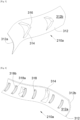
Fig. 2 est une représentation schématique en perspective d'une structure intérieure fixe selon l'invention, -
Fig. 3 est une vue en perspective et de face d'une éclisse pour la structure intérieure fixe selon l'invention, -
Fig. 4 est une vue en perspective et de dos de l'éclisse de laFig. 3 , -
Fig. 5 est une vue en coupe de la structure intérieure fixe selon l'invention au niveau du plan V de laFig. 2 , et -
Fig. 6 est une vue en coupe d'une structure intérieure fixe de l'état de la technique. - La
Fig. 1 montre un aéronef 100 qui comporte un fuselage 102 de part et d'autre duquel est fixée une aile 104 sous laquelle est fixée au moins une nacelle 106 par l'intermédiaire d'un mât réacteur 108. À l'intérieur de la nacelle 106 est logé un moteur. - Dans la description qui suit, et par convention, on appelle X l'axe longitudinal de la nacelle 106, orienté positivement dans le sens d'avancement de l'aéronef 100, on appelle Y l'axe transversal qui est horizontal lorsque l'aéronef 100 est au sol, et Z l'axe vertical ou hauteur verticale lorsque l'aéronef 100 est au sol, ces trois directions X, Y et Z étant orthogonales entre elles.
- Dans la description qui suit, les termes relatifs à une position sont pris en référence au sens de déplacement de l'aéronef 100 lorsque la turbomachine fonctionne et représenté par la flèche F.
- La
Fig. 2 montre une structure intérieure fixe 200 selon l'invention. Comme pour l'état de la technique, la nacelle 106 comporte deux structures intérieures fixes 200 (également appelées IFS pour « Internal Fix Structure » en terminologie anglo-saxonne) et deux structures extérieures 202 (également appelées OS pour « Outer Structure » en terminologie anglo-saxonne). - Chaque structure 200, 202 comporte une partie formant globalement un demi-cylindre et les deux structures intérieures fixes 200 sont disposées l'une en face de l'autre de manière à ce que les deux demi-cylindres s'associent pour former un cylindre dans lequel est logé le moteur 204. Les deux structures extérieures 202 sont disposées autour des structures intérieures fixes 200 de manière à former une veine d'air secondaire 50 entre les structures intérieures fixes 200 et les structures extérieures 202.
- La structure intérieure fixe 200 est constituée d'un panneau d'extrémité supérieure 200a, d'un panneau intermédiaire 200c et d'un panneau d'extrémité inférieure 200b. Les panneaux d'extrémité 200a-b sont globalement plans et le panneau intermédiaire 200c forme globalement un demi-cylindre, et il est disposé et fixé entre les panneaux d'extrémité 200a-b pour former la structure intérieure fixe 200. En position dans l'aéronef 100, le panneau d'extrémité supérieure 200a est disposé au-dessus du panneau intermédiaire 200c et le panneau d'extrémité inférieure 200b est disposé en-dessous du panneau intermédiaire 200c. Ainsi, dans la nacelle 106, les deux structures intérieures fixes 200 sont l'une en face de l'autre, de manière à ce que les panneaux intermédiaires 200c soient en face l'un de l'autre pour former le cylindre dans lequel est logé le moteur 204.
- La structure intérieure fixe 200 présente une jonction supérieure 208a entre le panneau d'extrémité supérieure 200a et le panneau intermédiaire 200c et une jonction inférieure 208b entre le panneau intermédiaire 200c et le panneau d'extrémité inférieure 200b. La
Fig. 5 montre la structure intérieure fixe 200 au niveau de la jonction supérieure 208a, mais l'arrangement est similaire au niveau de la jonction inférieure 208b. - Selon l'invention, au niveau de la jonction supérieure 208a, la structure intérieure fixe 200 comporte une éclisse supérieure 210a et au niveau de la jonction inférieure 208b, la structure intérieure fixe 200 comporte une éclisse inférieure 210b. Chaque éclisse 210a-b assure la jonction et la fixation entre le panneau intermédiaire 200c et le panneau d'extrémité 200a-b considéré.
- Les
Figs. 3 et 4 montrent l'éclisse supérieure 210a, mais le principe est identique pour l'éclisse inférieure 210b. L'éclisse 210a-b est constituée d'une peau 312 présentant une face intérieure 312a et une face extérieure 312b où la face intérieure 312a est fixée au panneau intermédiaire 200c et au panneau d'extrémité 200a-b considéré. - La tranche du panneau intermédiaire 200c et la tranche du panneau d'extrémité 200a-b considéré sont à distance l'une de l'autre, et l'éclisse 210a-b vient ainsi combler l'espace entre lesdites tranches et les maintenir entre elles.
- La peau 312 est ainsi conformée en fonction de la forme de la structure intérieure fixe 200 et elle comporte un ou plusieurs enfoncements 314, où chaque enfoncement 314 est en saillie par rapport à la face extérieure 312b. Chaque enfoncement 314 est donc monobloc avec la peau 312, formant ainsi un unique composant. Chaque enfoncement 314 forme ainsi un bossage du côté de la face extérieure 312b et un évidement du côté de la face intérieure 312a. La fixation de la peau 312 est assurée par tous moyens appropriés comme la pose de fixations 504 tels que des boulons aveugles, le collage, etc.
- Chaque enfoncement 314 présente une surface de fixation 316 sur laquelle est fixé un patin 506.
- Au niveau de la jonction supérieure 208a et donc de l'éclisse supérieure 210a, les deux structures intérieures fixes 200 se présentent de part et d'autre du mât réacteur 108 et chaque patin 506 d'une éclisse supérieure 210a vient en appui contre une surface du mât réacteur 108. Au niveau de la jonction inférieure 208b, et donc de l'éclisse inférieure 210b, les deux structures intérieures fixes 200 se présentent l'une en face de l'autre, et chaque patin 506 de l'éclisse inférieure 210b d'une structure intérieure fixe 200 vient en appui contre un patin 506 de l'éclisse inférieure 210b de l'autre structure intérieure fixe 200.
- Ainsi, avec un tel arrangement, il n'est plus nécessaire de mettre en place une structure en nid d'abeilles flexible, d'où un gain financier. L'intégration des enfoncements dans l'éclisse permet d'obtenir un seul composant qui peut être facilement mis en place, au lieu d'en avoir plusieurs dans le cas de l'état de la technique.
- Chaque éclisse 210a-b peut être réalisée en tous matériaux appropriés comme en métal (alliages d'aluminium, acier), en composite thermodurcissable ou thermoplastique, et par tous procédés appropriés comme par estampage, emboutissage, moulage, usinage ou autres.
- Dans le mode de réalisation de l'invention présenté à la
Fig. 5 , chaque panneau 200a-c prend la forme d'un panneau sandwich comportant successivement une peau résistive 500a, une structure en nid d'abeilles 500b et une peau structurale 500c qui sont fixées les unes aux autres. - La peau structurale 500c et la structure en nid d'abeilles 500b assurent la rigidité du panneau 200a-c et assurent la reprise des efforts qui transitent dans le panneau 200a-c.
- La peau résistive 500a est percée de trous qui débouchent dans la structure en nid d'abeilles 500b pour assurer une absorption des ondes acoustiques. La peau résistive 500a est disposée vers la veine d'air secondaire 50 et la peau structurale 500c est orientée vers le moteur 204. La structure en nid d'abeilles 500b est constituée de cellules ouvertes qui s'étendent entre la peau résistive 500a et la peau structurale 500c.
- Dans un mode de réalisation de l'invention non représenté, la face intérieure 312a de chaque éclisse 210a-b est fixée aux peaux structurales 500c du panneau intermédiaire 200c et du panneau d'extrémité 200a-b considéré.
- Dans le mode de réalisation de l'invention présenté à la
Fig. 5 , chaque panneau 200a-c comporte également une peau de fermeture 502 qui est conformée pour être fixée à la peau structurale 500c dudit panneau 200a-c et à la tranche dudit panneau 200a-c pour fermer la structure en nid d'abeilles 500b. Dans ce mode de réalisation de l'invention, la face intérieure 312a de chaque éclisse 210a-b est fixée aux peaux de fermeture 502 du panneau intermédiaire 200c et du panneau d'extrémité 200a-b considéré. - En outre, dans le mode de réalisation de l'invention présenté à la
Fig. 5 , une peau complémentaire 501 est fixée entre les peaux résistives 500a du panneau intermédiaire 200c et du panneau d'extrémité 200a-b, formant la jonction 208a-b considérée. Les peaux de fermeture 502 du panneau intermédiaire 200c et du panneau d'extrémité 200a-b considéré sont communes et forment alors une même peau qui est accolée contre la peau complémentaire 501. - Dans le mode de réalisation de l'invention présenté à la
Fig. 5 , une structure complémentaire en nid d'abeilles 503 est fixée entre la peau complémentaire 501 et la/les peau(x) de fermeture 502. - Pour régler la rigidité de la peau 312 de l'éclisse 210a-b, des raidisseurs 318 ou boudinages ou gaufrages (« corrugation » en terminologie anglosaxonne) sont disposés contre la face intérieure 312a. Dans le cas des raidisseurs 318, ces derniers sont fixés à la face intérieure 312a. Chaque raidisseur 318 ou boudinage ou gaufrage est positionné dans l'espace entre la tranche du panneau intermédiaire 200c et la tranche du panneau d'extrémité 200a-b considéré. Dans le mode de réalisation de l'invention présenté à la
Fig. 5 , chaque raidisseur 318 est ainsi disposé entre la peau 312 de l'éclisse 210a-b et la peau de fermeture 502 entre le panneau intermédiaire 200c et le panneau d'extrémité 200a-b. - Selon le procédé mis en oeuvre pour réaliser l'éclisse 210a-b, chaque raidisseur 318 est ajouté par surmoulage, liaison mécanique, soudage, etc.
- Chaque raidisseur 318 ou boudinage ou gaufrage comporte ici une plaque 318a fixée à la peau 312 de l'éclisse 210a-b et qui est ici cintrée.
- En fonction des contraintes, chaque raidisseur 318 ou boudinage ou gaufrage peut comporter également une paroi 318b solidaire de la plaque 318a et s'étendant perpendiculairement à la plaque 318a.
Claims (10)
- Structure intérieure fixe (200) pour une nacelle (106) d'un aéronef (100) comportant un mât réacteur (108), ladite structure intérieure fixe (200) comportant :- un panneau d'extrémité supérieure (200a),- un panneau d'extrémité inférieure (200b),- un panneau intermédiaire (200c) en forme de demi-cylindre et disposé entre le panneau d'extrémité supérieure (200a) et le panneau d'extrémité inférieure (200b),- une éclisse supérieure (210a) entre le panneau d'extrémité supérieure (200a) et le panneau intermédiaire (200c),- une éclisse inférieure (210b) entre le panneau intermédiaire (200c) et le panneau d'extrémité inférieure (200b), où chaque éclisse (210a-b) est constituée d'une peau (312) avec une face intérieure (312a) et une face extérieure (312b), où la face intérieure (312a) est fixée au panneau intermédiaire (200c) et au panneau d'extrémité (200a-b) considéré, et où la peau (312) comporte au moins un enfoncement (314) en saillie par rapport à la face extérieure (312b), où chaque enfoncement (314) présente une surface de fixation (316), et- pour chaque surface de fixation (316), un patin (506) fixé à ladite surface de fixation (316), où chaque patin (506) de l'éclisse supérieure (210a) est destiné à venir en appui contre une surface du mât réacteur (108), et où chaque patin (506) de l'éclisse inférieure (210b) est destiné à venir en appui contre un patin (506) d'une éclisse inférieure (210b) d'une autre structure intérieure fixe (200).
- Structure intérieure fixe (200) selon la revendication 1, caractérisée en ce que chaque panneau (200a-c) est un panneau sandwich comportant successivement une peau résistive (500a), une structure en nid d'abeilles (500b) et une peau structurale (500c), fixées entre elles, où la face intérieure (312a) de chaque éclisse (210a-b) est fixée aux peaux structurales (500c) du panneau intermédiaire (200c) et du panneau d'extrémité (200a-b) considéré.
- Structure intérieure fixe (200) selon la revendication 1, caractérisée en ce que chaque panneau (200a-c) est un panneau sandwich comportant successivement une peau résistive (500a), une structure en nid d'abeilles (500b), une peau structurale (500c), fixées entre elles, et une peau de fermeture (502) conformée pour être fixée à la peau structurale (500c) et à la tranche dudit panneau (200a-c), où la face intérieure (312a) de chaque éclisse (210a-b) est fixée aux peaux de fermeture (502) du panneau intermédiaire (200c) et du panneau d'extrémité (200a-b) considéré.
- Structure intérieure fixe (200) selon la revendication 3, caractérisée en ce qu'elle comporte une peau complémentaire (501) fixée entre les peaux résistives (500a) du panneau intermédiaire (200c) et du panneau d'extrémité (200a-b) considéré, et en ce que les peaux de fermeture (502) du panneau intermédiaire (200c) et du panneau d'extrémité (200a-b) considéré sont communes et forment alors une même peau accolée contre la peau complémentaire (501).
- Structure intérieure fixe (200) selon la revendication 4, caractérisée en ce qu'elle comporte une structure complémentaire en nid d'abeilles (503) fixée entre la peau complémentaire (501) et la/les peau(x) de fermeture (502).
- Structure intérieure fixe (200) selon l'une des revendications 1 à 5, caractérisée en ce que la tranche du panneau intermédiaire (200c) et la tranche d'un panneau d'extrémité (200a-b) considéré sont à distance l'une de l'autre, en ce que l'éclisse (210a-b) considérée comporte des raidisseurs (318) ou boudinages ou gaufrages disposés contre la face intérieure (312a) de la peau (312) de ladite éclisse (210a-b), et en ce que chaque raidisseur (318) ou boudinage ou gaufrage est positionné entre la tranche du panneau intermédiaire (200c) et la tranche dudit panneau d'extrémité (200a-b).
- Structure intérieure fixe (200) selon la revendication 6, caractérisé en ce que chaque raidisseur (318) ou boudinage ou gaufrage comporte une plaque (318a) fixée à la peau (312) de l'éclisse (210a-b).
- Structure intérieure fixe (200) selon la revendication 7, caractérisée en ce que chaque raidisseur (318) ou boudinage ou gaufrage comporte une paroi (318b) solidaire de la plaque (318a) et s'étendant perpendiculairement à la plaque (318a).
- Nacelle (106) pour un aéronef (100) comportant un mât réacteur (108), la nacelle (106) comportant deux structures intérieures fixes (200) selon l'une des revendications 1 à 8, où les deux structures intérieures fixes (200) sont l'une en face de l'autre, de manière à ce que les panneaux intermédiaires (200c) forment un cylindre, où chaque patin (506) de l'éclisse inférieure (210b) d'une structure intérieure fixe (200) est en appui contre un patin (506) de l'éclisse inférieure (210b) de l'autre structure intérieure fixe (200).
- Aéronef (100) comportant un mât réacteur (108) et au moins une nacelle (106) selon la revendication précédente, où chaque patin (506) de l'éclisse supérieure (210a) d'une structure intérieure fixe (200) est en appui contre une surface du mât réacteur (108).
Applications Claiming Priority (1)
| Application Number | Priority Date | Filing Date | Title |
|---|---|---|---|
| FR2304078A FR3148007A1 (fr) | 2023-04-24 | 2023-04-24 | Structure intérieure fixe pour une nacelle d’aéronef |
Publications (2)
| Publication Number | Publication Date |
|---|---|
| EP4455016A1 true EP4455016A1 (fr) | 2024-10-30 |
| EP4455016B1 EP4455016B1 (fr) | 2025-11-19 |
Family
ID=87136653
Family Applications (1)
| Application Number | Title | Priority Date | Filing Date |
|---|---|---|---|
| EP24171609.1A Active EP4455016B1 (fr) | 2023-04-24 | 2024-04-22 | Structure intérieure fixe pour une nacelle d'aéronef |
Country Status (4)
| Country | Link |
|---|---|
| US (1) | US12397921B2 (fr) |
| EP (1) | EP4455016B1 (fr) |
| CN (1) | CN118833402A (fr) |
| FR (1) | FR3148007A1 (fr) |
Citations (5)
| Publication number | Priority date | Publication date | Assignee | Title |
|---|---|---|---|---|
| US5101621A (en) * | 1989-09-25 | 1992-04-07 | Rohr Industries, Inc. | Integrated corner for ducted fan engine shrouds |
| US20150041059A1 (en) * | 2013-03-18 | 2015-02-12 | Rohr, Inc. | Inner fixed structure with attached corner fitting |
| US20150136875A1 (en) * | 2013-11-15 | 2015-05-21 | Rohr, Inc. | System and method for mounting of thrust reverser to pylon |
| US20150143796A1 (en) * | 2013-11-27 | 2015-05-28 | Rohr, Inc. | System and method for captured inner fixed structure |
| WO2019155015A1 (fr) | 2018-02-09 | 2019-08-15 | Safran Nacelles Limited | Structure fixe interne d'inverseur de poussée |
-
2023
- 2023-04-24 FR FR2304078A patent/FR3148007A1/fr not_active Ceased
-
2024
- 2024-04-22 EP EP24171609.1A patent/EP4455016B1/fr active Active
- 2024-04-23 US US18/643,483 patent/US12397921B2/en active Active
- 2024-04-23 CN CN202410491702.8A patent/CN118833402A/zh active Pending
Patent Citations (5)
| Publication number | Priority date | Publication date | Assignee | Title |
|---|---|---|---|---|
| US5101621A (en) * | 1989-09-25 | 1992-04-07 | Rohr Industries, Inc. | Integrated corner for ducted fan engine shrouds |
| US20150041059A1 (en) * | 2013-03-18 | 2015-02-12 | Rohr, Inc. | Inner fixed structure with attached corner fitting |
| US20150136875A1 (en) * | 2013-11-15 | 2015-05-21 | Rohr, Inc. | System and method for mounting of thrust reverser to pylon |
| US20150143796A1 (en) * | 2013-11-27 | 2015-05-28 | Rohr, Inc. | System and method for captured inner fixed structure |
| WO2019155015A1 (fr) | 2018-02-09 | 2019-08-15 | Safran Nacelles Limited | Structure fixe interne d'inverseur de poussée |
Also Published As
| Publication number | Publication date |
|---|---|
| FR3148007A1 (fr) | 2024-10-25 |
| US20240351697A1 (en) | 2024-10-24 |
| US12397921B2 (en) | 2025-08-26 |
| EP4455016B1 (fr) | 2025-11-19 |
| CN118833402A (zh) | 2024-10-25 |
Similar Documents
| Publication | Publication Date | Title |
|---|---|---|
| EP3394399B1 (fr) | Aube, soufflante et turboréacteur associés | |
| WO2008029048A1 (fr) | Procede de realisation d'un assemblage de panneaux | |
| EP3380399B1 (fr) | Avion propulse par une turbomachine muni d'un ecran acoustique | |
| EP3486174B1 (fr) | Attache moteur arriere pour un moteur d'aeronef | |
| EP1945502B1 (fr) | Aeronef comportant un carenage central ajusteur de pression voilure par déformations geometriques locales | |
| EP1544481B1 (fr) | Tôle comportant des moyens de fixation à un support et un joint d'étanchéité | |
| EP3521173B1 (fr) | Ensemble pour aeronef comprenant une structure primaire de mat d'accrochage fixee a un caisson de voilure a l'aide d'une liaison boulonnee | |
| EP4484297B1 (fr) | Système d'attache moteur avant pour un moteur d'aéronef qui comporte une structure compacte | |
| EP1535840B1 (fr) | Ensemble pour aéronef comprenant un dispositif de montage d'un carénage disposé entre une entrée d'air d'un moteur d'aéronef et un mât | |
| FR3096028A1 (fr) | Attache moteur arriere pour un moteur d’aeronef | |
| EP3476740A1 (fr) | Structure primaire de mât de support d'un groupe propulseur d'aéronef en caisson formée par assemblage de deux demi-coquilles | |
| EP4455016B1 (fr) | Structure intérieure fixe pour une nacelle d'aéronef | |
| EP3495651A1 (fr) | Grille pour la formation d'un flux d'inversion d'un turboréacteur d'aéronef | |
| EP3366955A1 (fr) | Joint d'etancheite souple pour un aeronef | |
| FR3013678A1 (fr) | Carenage aerodynamique | |
| EP1331402B1 (fr) | Dispositif de commande d'aube variable | |
| FR3091263A1 (fr) | Bec de bord d’attaque à structure optimisée | |
| WO2024246452A1 (fr) | Procede de fabrication d'un panneau aerodynamique pour un ensemble propulsif d'aeronef | |
| EP4173961B1 (fr) | Nacelle d aéronef comprenant une liaison entre des conduits comportant des collerettes orientées vers l' intérieur et aéronef comprenant au moins une telle nacelle | |
| FR3078951A1 (fr) | Turboreacteur comportant une nacelle equipee d'un carter de soufflante et d'une structure fixe | |
| EP4253031B1 (fr) | Panneau acoustique comprenant au moins deux structures alvéolaires imbriquées l'une dans l'autre, aéronef comportant au moins un tel panneau acoustique | |
| FR3021029A1 (fr) | Carenage aerodynamique | |
| EP4467462A1 (fr) | Carénage d'aéronef comportant un panneau démontable et un joint d'étanchéité compressible, aéronef comportant au moins un tel carénage | |
| EP4129825B1 (fr) | Ensemble pour une nacelle d'un moteur d'aéronef, ledit ensemble comportant un capot fixe et un capot monté mobile sur le capot fixe | |
| EP4644256A1 (fr) | Lèvre d'entrée d'air pour une nacelle d'un turboréacteur double flux d'aéronef |
Legal Events
| Date | Code | Title | Description |
|---|---|---|---|
| PUAI | Public reference made under article 153(3) epc to a published international application that has entered the european phase |
Free format text: ORIGINAL CODE: 0009012 |
|
| STAA | Information on the status of an ep patent application or granted ep patent |
Free format text: STATUS: THE APPLICATION HAS BEEN PUBLISHED |
|
| AK | Designated contracting states |
Kind code of ref document: A1 Designated state(s): AL AT BE BG CH CY CZ DE DK EE ES FI FR GB GR HR HU IE IS IT LI LT LU LV MC ME MK MT NL NO PL PT RO RS SE SI SK SM TR |
|
| STAA | Information on the status of an ep patent application or granted ep patent |
Free format text: STATUS: REQUEST FOR EXAMINATION WAS MADE |
|
| 17P | Request for examination filed |
Effective date: 20250422 |
|
| GRAP | Despatch of communication of intention to grant a patent |
Free format text: ORIGINAL CODE: EPIDOSNIGR1 |
|
| STAA | Information on the status of an ep patent application or granted ep patent |
Free format text: STATUS: GRANT OF PATENT IS INTENDED |
|
| RIC1 | Information provided on ipc code assigned before grant |
Ipc: F02C 7/20 20060101ALI20250528BHEP Ipc: F01D 25/28 20060101ALI20250528BHEP Ipc: F01D 25/16 20060101ALI20250528BHEP Ipc: F02K 1/78 20060101ALI20250528BHEP Ipc: B64D 29/06 20060101AFI20250528BHEP |
|
| INTG | Intention to grant announced |
Effective date: 20250620 |
|
| GRAS | Grant fee paid |
Free format text: ORIGINAL CODE: EPIDOSNIGR3 |
|
| GRAA | (expected) grant |
Free format text: ORIGINAL CODE: 0009210 |
|
| STAA | Information on the status of an ep patent application or granted ep patent |
Free format text: STATUS: THE PATENT HAS BEEN GRANTED |
|
| AK | Designated contracting states |
Kind code of ref document: B1 Designated state(s): AL AT BE BG CH CY CZ DE DK EE ES FI FR GB GR HR HU IE IS IT LI LT LU LV MC ME MK MT NL NO PL PT RO RS SE SI SK SM TR |
|
| REG | Reference to a national code |
Ref country code: CH Ref legal event code: F10 Free format text: ST27 STATUS EVENT CODE: U-0-0-F10-F00 (AS PROVIDED BY THE NATIONAL OFFICE) Effective date: 20251119 Ref country code: GB Ref legal event code: FG4D Free format text: NOT ENGLISH |
|
| REG | Reference to a national code |
Ref country code: DE Ref legal event code: R096 Ref document number: 602024001296 Country of ref document: DE |
|
| REG | Reference to a national code |
Ref country code: IE Ref legal event code: FG4D Free format text: LANGUAGE OF EP DOCUMENT: FRENCH |
|
| REG | Reference to a national code |
Ref country code: NL Ref legal event code: MP Effective date: 20251119 |
|
| PG25 | Lapsed in a contracting state [announced via postgrant information from national office to epo] |
Ref country code: ES Free format text: LAPSE BECAUSE OF FAILURE TO SUBMIT A TRANSLATION OF THE DESCRIPTION OR TO PAY THE FEE WITHIN THE PRESCRIBED TIME-LIMIT Effective date: 20251119 |
|
| REG | Reference to a national code |
Ref country code: LT Ref legal event code: MG9D |
|
| PG25 | Lapsed in a contracting state [announced via postgrant information from national office to epo] |
Ref country code: NO Free format text: LAPSE BECAUSE OF FAILURE TO SUBMIT A TRANSLATION OF THE DESCRIPTION OR TO PAY THE FEE WITHIN THE PRESCRIBED TIME-LIMIT Effective date: 20260219 |
|
| PG25 | Lapsed in a contracting state [announced via postgrant information from national office to epo] |
Ref country code: AT Free format text: LAPSE BECAUSE OF FAILURE TO SUBMIT A TRANSLATION OF THE DESCRIPTION OR TO PAY THE FEE WITHIN THE PRESCRIBED TIME-LIMIT Effective date: 20251119 Ref country code: HR Free format text: LAPSE BECAUSE OF FAILURE TO SUBMIT A TRANSLATION OF THE DESCRIPTION OR TO PAY THE FEE WITHIN THE PRESCRIBED TIME-LIMIT Effective date: 20251119 Ref country code: FI Free format text: LAPSE BECAUSE OF FAILURE TO SUBMIT A TRANSLATION OF THE DESCRIPTION OR TO PAY THE FEE WITHIN THE PRESCRIBED TIME-LIMIT Effective date: 20251119 |
|
| REG | Reference to a national code |
Ref country code: AT Ref legal event code: MK05 Ref document number: 1858647 Country of ref document: AT Kind code of ref document: T Effective date: 20251119 |
|
| PG25 | Lapsed in a contracting state [announced via postgrant information from national office to epo] |
Ref country code: NL Free format text: LAPSE BECAUSE OF FAILURE TO SUBMIT A TRANSLATION OF THE DESCRIPTION OR TO PAY THE FEE WITHIN THE PRESCRIBED TIME-LIMIT Effective date: 20251119 |
|
| PG25 | Lapsed in a contracting state [announced via postgrant information from national office to epo] |
Ref country code: RS Free format text: LAPSE BECAUSE OF FAILURE TO SUBMIT A TRANSLATION OF THE DESCRIPTION OR TO PAY THE FEE WITHIN THE PRESCRIBED TIME-LIMIT Effective date: 20260219 |
|
| PG25 | Lapsed in a contracting state [announced via postgrant information from national office to epo] |
Ref country code: IS Free format text: LAPSE BECAUSE OF FAILURE TO SUBMIT A TRANSLATION OF THE DESCRIPTION OR TO PAY THE FEE WITHIN THE PRESCRIBED TIME-LIMIT Effective date: 20260319 |
|
| PG25 | Lapsed in a contracting state [announced via postgrant information from national office to epo] |
Ref country code: PT Free format text: LAPSE BECAUSE OF FAILURE TO SUBMIT A TRANSLATION OF THE DESCRIPTION OR TO PAY THE FEE WITHIN THE PRESCRIBED TIME-LIMIT Effective date: 20260319 |
|
| PG25 | Lapsed in a contracting state [announced via postgrant information from national office to epo] |
Ref country code: PL Free format text: LAPSE BECAUSE OF FAILURE TO SUBMIT A TRANSLATION OF THE DESCRIPTION OR TO PAY THE FEE WITHIN THE PRESCRIBED TIME-LIMIT Effective date: 20251119 |
|
| PG25 | Lapsed in a contracting state [announced via postgrant information from national office to epo] |
Ref country code: LV Free format text: LAPSE BECAUSE OF FAILURE TO SUBMIT A TRANSLATION OF THE DESCRIPTION OR TO PAY THE FEE WITHIN THE PRESCRIBED TIME-LIMIT Effective date: 20251119 |
|
| PG25 | Lapsed in a contracting state [announced via postgrant information from national office to epo] |
Ref country code: BG Free format text: LAPSE BECAUSE OF FAILURE TO SUBMIT A TRANSLATION OF THE DESCRIPTION OR TO PAY THE FEE WITHIN THE PRESCRIBED TIME-LIMIT Effective date: 20251119 |