EP4454962A1 - Valve, pneumatic system and vehicle, in particular utility vehicle - Google Patents
Valve, pneumatic system and vehicle, in particular utility vehicle Download PDFInfo
- Publication number
- EP4454962A1 EP4454962A1 EP23170559.1A EP23170559A EP4454962A1 EP 4454962 A1 EP4454962 A1 EP 4454962A1 EP 23170559 A EP23170559 A EP 23170559A EP 4454962 A1 EP4454962 A1 EP 4454962A1
- Authority
- EP
- European Patent Office
- Prior art keywords
- valve
- shuttle member
- cylinder
- vehicle
- supply port
- Prior art date
- Legal status (The legal status is an assumption and is not a legal conclusion. Google has not performed a legal analysis and makes no representation as to the accuracy of the status listed.)
- Granted
Links
Images
Classifications
-
- F—MECHANICAL ENGINEERING; LIGHTING; HEATING; WEAPONS; BLASTING
- F16—ENGINEERING ELEMENTS AND UNITS; GENERAL MEASURES FOR PRODUCING AND MAINTAINING EFFECTIVE FUNCTIONING OF MACHINES OR INSTALLATIONS; THERMAL INSULATION IN GENERAL
- F16K—VALVES; TAPS; COCKS; ACTUATING-FLOATS; DEVICES FOR VENTING OR AERATING
- F16K11/00—Multiple-way valves, e.g. mixing valves; Pipe fittings incorporating such valves
- F16K11/02—Multiple-way valves, e.g. mixing valves; Pipe fittings incorporating such valves with all movable sealing faces moving as one unit
- F16K11/04—Multiple-way valves, e.g. mixing valves; Pipe fittings incorporating such valves with all movable sealing faces moving as one unit comprising only lift valves
- F16K11/044—Multiple-way valves, e.g. mixing valves; Pipe fittings incorporating such valves with all movable sealing faces moving as one unit comprising only lift valves with movable valve members positioned between valve seats
-
- B—PERFORMING OPERATIONS; TRANSPORTING
- B60—VEHICLES IN GENERAL
- B60G—VEHICLE SUSPENSION ARRANGEMENTS
- B60G17/00—Resilient suspensions having means for adjusting the spring or vibration-damper characteristics, for regulating the distance between a supporting surface and a sprung part of vehicle or for locking suspension during use to meet varying vehicular or surface conditions, e.g. due to speed or load
- B60G17/02—Spring characteristics, e.g. mechanical springs and mechanical adjusting means
- B60G17/04—Spring characteristics, e.g. mechanical springs and mechanical adjusting means fluid spring characteristics
- B60G17/052—Pneumatic spring characteristics
- B60G17/0523—Regulating distributors or valves for pneumatic springs
-
- B—PERFORMING OPERATIONS; TRANSPORTING
- B60—VEHICLES IN GENERAL
- B60T—VEHICLE BRAKE CONTROL SYSTEMS OR PARTS THEREOF; BRAKE CONTROL SYSTEMS OR PARTS THEREOF, IN GENERAL; ARRANGEMENT OF BRAKING ELEMENTS ON VEHICLES IN GENERAL; PORTABLE DEVICES FOR PREVENTING UNWANTED MOVEMENT OF VEHICLES; VEHICLE MODIFICATIONS TO FACILITATE COOLING OF BRAKES
- B60T11/00—Transmitting braking action from initiating means to ultimate brake actuator without power assistance or drive or where such assistance or drive is irrelevant
- B60T11/10—Transmitting braking action from initiating means to ultimate brake actuator without power assistance or drive or where such assistance or drive is irrelevant transmitting by fluid means, e.g. hydraulic
- B60T11/28—Valves specially adapted therefor
-
- B—PERFORMING OPERATIONS; TRANSPORTING
- B60—VEHICLES IN GENERAL
- B60T—VEHICLE BRAKE CONTROL SYSTEMS OR PARTS THEREOF; BRAKE CONTROL SYSTEMS OR PARTS THEREOF, IN GENERAL; ARRANGEMENT OF BRAKING ELEMENTS ON VEHICLES IN GENERAL; PORTABLE DEVICES FOR PREVENTING UNWANTED MOVEMENT OF VEHICLES; VEHICLE MODIFICATIONS TO FACILITATE COOLING OF BRAKES
- B60T13/00—Transmitting braking action from initiating means to ultimate brake actuator with power assistance or drive; Brake systems incorporating such transmitting means, e.g. air-pressure brake systems
- B60T13/10—Transmitting braking action from initiating means to ultimate brake actuator with power assistance or drive; Brake systems incorporating such transmitting means, e.g. air-pressure brake systems with fluid assistance, drive, or release
- B60T13/24—Transmitting braking action from initiating means to ultimate brake actuator with power assistance or drive; Brake systems incorporating such transmitting means, e.g. air-pressure brake systems with fluid assistance, drive, or release the fluid being gaseous
- B60T13/26—Compressed-air systems
-
- B—PERFORMING OPERATIONS; TRANSPORTING
- B60—VEHICLES IN GENERAL
- B60T—VEHICLE BRAKE CONTROL SYSTEMS OR PARTS THEREOF; BRAKE CONTROL SYSTEMS OR PARTS THEREOF, IN GENERAL; ARRANGEMENT OF BRAKING ELEMENTS ON VEHICLES IN GENERAL; PORTABLE DEVICES FOR PREVENTING UNWANTED MOVEMENT OF VEHICLES; VEHICLE MODIFICATIONS TO FACILITATE COOLING OF BRAKES
- B60T15/00—Construction arrangement, or operation of valves incorporated in power brake systems and not covered by groups B60T11/00 or B60T13/00
- B60T15/02—Application and release valves
- B60T15/36—Other control devices or valves characterised by definite functions
-
- F—MECHANICAL ENGINEERING; LIGHTING; HEATING; WEAPONS; BLASTING
- F16—ENGINEERING ELEMENTS AND UNITS; GENERAL MEASURES FOR PRODUCING AND MAINTAINING EFFECTIVE FUNCTIONING OF MACHINES OR INSTALLATIONS; THERMAL INSULATION IN GENERAL
- F16K—VALVES; TAPS; COCKS; ACTUATING-FLOATS; DEVICES FOR VENTING OR AERATING
- F16K15/00—Check valves
- F16K15/02—Check valves with guided rigid valve members
Definitions
- the disclosure relates to a valve for a pneumatic system of a vehicle, in particular utility vehicle, wherein the valve comprises: a cylinder; a pressure supply port to supply pressurized air to the cylinder; and a shuttle member being movably arranged within the cylinder, wherein the shuttle member is adapted to be moved by the supply of the pressurized air.
- the disclosure further relates to a pneumatic system for a vehicle, in particular utility vehicle, comprising a valve, and to a vehicle, in particular utility vehicle, comprising a pneumatic system.
- Double check valves are known in the prior art.
- Such a valve may comprise a so-called shuttle member, a cylinder, and an o-ring.
- the shuttle member is movably arranged within the cylinder.
- the shuttle member typically comprises a metal body and an overmolded rubber layer.
- the o-ring is used as a radial sealing to seal the shuttle member from the cylinder.
- the shuttle member comprises at least two separate aspects: the shuttle member being made of a metal insert overmolded with rubber, and o-rings to provide a radial sealing.
- this may cause a risk of leakage if the o-rings are not or not firmly assembled. A risk of an unpredictable air flow may be caused if one or more of the o-rings is not fully tightened.
- detecting whether the o-rings have been mounted correctly may be difficult.
- the main function of the shuttle member is to select a higher pressure to be delivered independently to two supply ports. For example, if a first pressure at the first supply port is larger than a second pressure at a second supply port, the shuttle member moves towards the second supply port and blocks the airflow from the second supply port.
- EP 20 59 427 B1 discloses a valve unit for an electro-pneumatic brake control device for controlling a vehicle brake, wherein the valve unit can be or is connected to a control input of an air-quantity-boosting valve device and is designed for the controllable aeration and deaeration of said valve device via its control input.
- overload protection valve is provided.
- An embodiment of the present disclosure may solve the problem of providing a valve with an improved and cost-effective sealing between a shuttle member and a cylinder.
- a valve for a pneumatic system of a vehicle in particular utility vehicle, is provided.
- the valve comprises: a cylinder; a pressure supply port to supply pressurized air to the cylinder; and a shuttle member being movably arranged within the cylinder, wherein the shuttle member is adapted to be moved by the supply of the pressurized air; wherein the shuttle member comprises a radial lip seal being integrally formed with the shuttle member.
- the disclosure provides a with an integrally formed, i.e., integrated radial lip seal.
- the lip seal and a surface of the shuttle member may be one-piece.
- the lip seal is fixedly arranged at and/or attached to the surface of the shuttle member.
- the radial lip seal is adapted to contact an inner surface of the cylinder and thus seal the shuttle member from the inner surface of the cylinder.
- the lip seal may perform the same function as a sub-assembly of a shuttle member with o-rings. Hence, the o-rings may be dispensed with.
- the lip seal being integrally formed with the shuttle member achieves that only the shuttle member needs to be arranged within the cylinder to assemble the valve.
- the shuttle member and the o-rings need to be arranged within the cylinder to assemble the valve.
- the disclosure thus achieves a more efficient and thus cost-effective assembly of the valve.
- a proper assembly of the valve may be detected more reliably and efficiently, since a misarrangement of a component different from the shuttle member may be excluded. This may improve the sealing between the shuttle member and the cylinder. In particular, this may reliably reduce the risk of leakage as the radial shape of the lip seal helps to block the air flow from one port to the other.
- the shuttle member is a one-piece elastic element.
- the elasticity of the shuttle member thus defines the elasticity of the lip seal which influences the sealing performance.
- a single component shuttle member may be provided.
- the elastic element may provide the body and the sealing of the shuttle member.
- a core e.g., a metal core
- the shuttle member may comprise a body with a core, in particular a metal core.
- the cylinder defines an axial direction
- the shuttle member comprises a second radial lip seal being separated, in the axial direction, from the lip seal.
- the shuttle member may comprise two lip seal being arranged with a certain distance, in the axial direction, from each other. This may enable a more balanced sealing and prevent tilting of the shuttle member within the cylinder and may thus improve the performance of the valve.
- the lip seal is circumferentially arranged and protrudes from a cylinder surface of the shuttle member towards the cylinder.
- the cylinder surface, i.e., lateral surface, of the shuttle member may be a circumferential surface.
- the cylinder surface faces the inner surface of the cylinder.
- the radially protruding lip seal may protrude from the cylinder surface towards to inner surface and may contact the inner surface to provide sealing.
- the shuttle member is made of rubber.
- the rubber shuttle member may enable that the surface of the shuttle member and the lip seal are integrally formed.
- the rubber shuttle member may further enable that the shuttle member is a one-piece component. Rubber may enable an efficient and cost-effective manufacture of the shuttle member, e.g., by injection moudling.
- the valve is a double check valve.
- the double check valve may enable selecting a higher pressure being delivered by one of two supply ports.
- the shuttle member may move within the cylinder so as to block one of the supply ports.
- a pneumatic system for a vehicle in particular utility vehicle
- the pneumatic system comprises the valve as described above.
- the valve comprises one or more of the above-described optional features to achieve a corresponding technical effect.
- the pneumatic system is a pneumatic braking system.
- the pneumatic braking system may advantageously benefit from the improved sealing of the valve.
- the pneumatic valve may be an axle pressure control valve to control the pressure in braking chamber of the axle.
- there may be two supply ports between which the valve may be functionally provided to select air from the supply port with the larger pressure. Even if the difference between the pressures from the supply ports is not significant, leakage may be prevented with the valve, since the o-rings of the prior art as a potential origin of the leakage may be dispensed with.
- the pneumatic valve may be used in other pneumatic systems, such as a pneumatic suspension system and/or a pneumatically actuated transmission system.
- a vehicle in particular utility vehicle
- the vehicle comprises the pneumatic system as described above.
- the pneumatic system and/or the valve of the pneumatic system comprises one or more of the above-described optional features to achieve a corresponding technical effect.
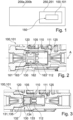
- FIG 1 shows a schematic of a vehicle 200a, in particular utility vehicle 200b, according to an embodiment of the disclosure.
- vehicle 200a in particular utility vehicle 200b
- vehicle 200a, 200b is referred to as vehicle 200a, 200b.
- the vehicle 200a, 200b is a land-vehicle.
- the vehicle 200a, 200b may be a truck, a bus and/or a trailer.
- the vehicle 200a, 200b comprises a pneumatic system 250.
- the pneumatic system 250 is pneumatic braking system 251.
- the pneumatic braking system 251 is adapted to apply a braking force to decelerate one or more wheels (not shown) of the vehicle 200a, 200b and/or the vehicle 200a, 200b.
- the pneumatic system 250 comprises a valve 100.
- the pneumatic system 250 is adapted to supply pressurized air 150 to the valve 100.
- the valve 100 is a double check valve 101.
- the valve 100 is further described with reference to Figure 3 .
- Figure 2 shows a cross-sectional view of a valve 100 according to the prior art.
- the valve 100 comprises a body 105 and a cylinder 110.
- the cylinder 110 is arranged within the body 105.
- the valve 100 comprises a pressure supply port 120, a second supply port 125 and a control section 112.
- Each of the supply port 120 and the second supply port 125 is adapted to inject pressurized air 150 (not indicated in Figure 2 ) into the cylinder 110 and in particular into the control section 112.
- the control section 112 may also be called control chamber, control room or control path.
- Each of the supply port 120 and the second supply port 125 comprises a nozzle (not indicated) to concentrate the application of pressurized air 150.
- the cylinder 110 defines an axial direction A. In the axial direction A, the cylinder 110 is arranged between the supply port 120 and the second supply port 125.
- the control section 112 is arranged, in the axial direction A, in a middle section (not indicated) of the cylinder 110, i.e., between the supply port 120 and the second supply port 125.
- the valve 100 comprises a shuttle member 130 being movably arranged within the cylinder 110.
- the functioning of the shuttle member 130 and of the valve 100 is described with reference to Figure 3 .
- the shuttle member 130 according to the prior art as shown in Figure 2 comprises a rubber part 161, a metal part 162 and two o-rings 163.
- the rubber part 161 extends, along the axis A, entirely through the shuttle member 130.
- the rubber part 161 is overmolded over the metal part 162.
- the metal part 162 comprises two circumferentially extended and axially separated recesses (not indicated). In each of the recesses, one of the o-rings 163 is arranged.
- the o-rings 163 are adapted to contact an inner surface 111 of the cylinder 110 to provide sealing.
- FIG 3 shows a cross-sectional view of a valve 100 according to an embodiment of the disclosure.
- the valve 100 is a valve 100 for a pneumatic system 250 of a vehicle 200a, 200b.
- a vehicle 200a, 200b and pneumatic system 250 is described with reference to Figure 1.
- Figure 3 is described under reference to Figure 1 .
- the valve 100 of Figure 1 is a double check valve 101.
- the valve 100 comprises a body 105 and a cylinder 110.
- the cylinder 110 is arranged within the body 105.
- the valve 100 comprises a pressure supply port 120, a second supply port 125 and an control section 112.
- Each of the supply port 120 and the second supply port 125 is a pressure supply port 120, 125 and adapted to inject pressurized air 150 (not indicated in Figure 2 ) into the cylinder 110.
- Each of the supply port 120 and the second supply port 125 comprises a nozzle (not indicated) to concentrate the application of pressurized air 150.
- the cylinder 110 defines an axial direction A. In the axial direction A, the cylinder 110 is arranged between the supply port 120 and the second supply port 125.
- the control section 112 is arranged, in the axial direction A, in a middle section (not indicated) of the cylinder 110, i.e., between the supply port 120 and the second supply port 125.
- the valve 100 comprises a shuttle member 130 being movably arranged within the cylinder 110.
- the shuttle member 130 is adapted to move along the axial direction A.
- the movement of the shuttle member 130 is limited, in a radial direction, by the cylinder 110 and, in the axial direction A, by one or more end stops (not indicated) which may be provided by the supply ports 120, 125 and/or the body 105.
- the shuttle member 130 is adapted to be moved by the supply of the pressurized air 150. I.e., if more pressurized air 150 is supplied by the supply port 120, the shuttle member 130 is pushed away from the supply port 120 towards the second supply port 125.
- the shuttle member 130 is adapted to stop at the end stop near the second supply port 125 to close the second supply port 125. At this time, the shuttle member 130 unblocks the control section 112 through which the pressurized air 150 is delivered to the control room. Conversely, if more pressurized air 150 is supplied by the second supply port 125, the shuttle member 130 is pushed away from the second supply port 125 towards the supply port 120. The shuttle member 130 is adapted to stop at the end stop near the supply port 120 to close the supply port 120. At this time, the shuttle member 130 unblocks the control section 112 through which the pressurized air 150 is delivered to the control room.
- the shuttle member 130 comprises a radial lip seal 132 being integrally formed with the shuttle member 130.
- the shuttle member 130 comprises a second radial lip seal 133 being separated, in the axial direction A, from the lip seal 132.
- the lip seals 132, 133 are integrally formed with the shuttle member 130 and thus with the cylinder surface 134.
- the lip seals 132, 133 and the cylinder surface 134 and/or the shuttle member 130 may be made of the same material.
- the shuttle member 130 is a one-piece elastic element 131 and made of rubber 135.
- the cylinder surface 134 and the lip seals 132, 133 may also be made from different materials which enable integrally forming the lips seals 132, 133 with the shuttle member 130, e.g., different plastic and/or rubber materials may be moulded together.
- Each of the lip seal 132 and the second lip seal 133 is circumferentially arranged and protrudes from a cylinder surface 134 of the shuttle member 130 towards the cylinder 110.
- the lip seals 132, 133 protrudes from cylinder surface 134 in a radial direction from the shuttle member 130 and contact an inner surface of the cylinder 111 and thus provide sealing.
- the double check valve 101 of Figure 3 with the integrated radial lip seals 132, 133 may replace the valve 100 as shown in Figure 2 with o-rings 163.
- the double check valve 101 of Figure 3 provides sealing with a single component.
- the double check valve 101 of Figure 3 is designed as a rubber element.
- the two o-rings 163, radial lip seals 132, 133 are integrated.
Landscapes
- Engineering & Computer Science (AREA)
- Mechanical Engineering (AREA)
- Transportation (AREA)
- General Engineering & Computer Science (AREA)
- Check Valves (AREA)
- Valves And Accessory Devices For Braking Systems (AREA)
Abstract
Description
- The disclosure relates to a valve for a pneumatic system of a vehicle, in particular utility vehicle, wherein the valve comprises: a cylinder; a pressure supply port to supply pressurized air to the cylinder; and a shuttle member being movably arranged within the cylinder, wherein the shuttle member is adapted to be moved by the supply of the pressurized air. The disclosure further relates to a pneumatic system for a vehicle, in particular utility vehicle, comprising a valve, and to a vehicle, in particular utility vehicle, comprising a pneumatic system.
- Double check valves are known in the prior art. Such a valve may comprise a so-called shuttle member, a cylinder, and an o-ring. The shuttle member is movably arranged within the cylinder. The shuttle member typically comprises a metal body and an overmolded rubber layer. The o-ring is used as a radial sealing to seal the shuttle member from the cylinder. I.e., the shuttle member comprises at least two separate aspects: the shuttle member being made of a metal insert overmolded with rubber, and o-rings to provide a radial sealing. However, this may cause a risk of leakage if the o-rings are not or not firmly assembled. A risk of an unpredictable air flow may be caused if one or more of the o-rings is not fully tightened. Furthermore, during manufacture of the valve, detecting whether the o-rings have been mounted correctly may be difficult.
- The main function of the shuttle member is to select a higher pressure to be delivered independently to two supply ports. For example, if a first pressure at the first supply port is larger than a second pressure at a second supply port, the shuttle member moves towards the second supply port and blocks the airflow from the second supply port.
- The at the filing date not published patent application
DE 10 2022 107 781.0 describes a double check valve, a pneumatic braking system and a vehicle, in particular utility vehicle. -
EP 20 59 427 B1 discloses a valve unit for an electro-pneumatic brake control device for controlling a vehicle brake, wherein the valve unit can be or is connected to a control input of an air-quantity-boosting valve device and is designed for the controllable aeration and deaeration of said valve device via its control input. To avoid a mechanical overuse of the brake mechanism designed as a shuttle valve or select high-valve, overload protection valve is provided. - The problem of the disclosure is to provide a technological contribution to the art. An embodiment of the present disclosure may solve the problem of providing a valve with an improved and cost-effective sealing between a shuttle member and a cylinder.
- The object is solved by the subject-matter according to independent claim 1 and according to the remaining independent claims. Dependent claims relate to preferred embodiments.
- According to an aspect of the disclosure, a valve for a pneumatic system of a vehicle, in particular utility vehicle, is provided. Therein, the valve comprises: a cylinder; a pressure supply port to supply pressurized air to the cylinder; and a shuttle member being movably arranged within the cylinder, wherein the shuttle member is adapted to be moved by the supply of the pressurized air; wherein the shuttle member comprises a radial lip seal being integrally formed with the shuttle member.
- The disclosure provides a with an integrally formed, i.e., integrated radial lip seal. In other words, the lip seal and a surface of the shuttle member may be one-piece. Thus, the lip seal is fixedly arranged at and/or attached to the surface of the shuttle member. The radial lip seal is adapted to contact an inner surface of the cylinder and thus seal the shuttle member from the inner surface of the cylinder. Thus, the lip seal may perform the same function as a sub-assembly of a shuttle member with o-rings. Hence, the o-rings may be dispensed with.
- The lip seal being integrally formed with the shuttle member achieves that only the shuttle member needs to be arranged within the cylinder to assemble the valve. In contrast, in the prior art, the shuttle member and the o-rings need to be arranged within the cylinder to assemble the valve. The disclosure thus achieves a more efficient and thus cost-effective assembly of the valve.
- By integrally forming the lip seal with the shuttle member, a proper assembly of the valve may be detected more reliably and efficiently, since a misarrangement of a component different from the shuttle member may be excluded. This may improve the sealing between the shuttle member and the cylinder. In particular, this may reliably reduce the risk of leakage as the radial shape of the lip seal helps to block the air flow from one port to the other.
- Optionally, the shuttle member is a one-piece elastic element. The elasticity of the shuttle member thus defines the elasticity of the lip seal which influences the sealing performance. Thus, a single component shuttle member may be provided. The elastic element may provide the body and the sealing of the shuttle member. Thus, a core, e.g., a metal core, may be dispensed with to enable a more cost-effective manufacture of the shuttle member. Alternatively, the shuttle member may comprise a body with a core, in particular a metal core.
- Optionally, the cylinder defines an axial direction, and the shuttle member comprises a second radial lip seal being separated, in the axial direction, from the lip seal. Thus, the shuttle member may comprise two lip seal being arranged with a certain distance, in the axial direction, from each other. This may enable a more balanced sealing and prevent tilting of the shuttle member within the cylinder and may thus improve the performance of the valve.
- Optionally, the lip seal is circumferentially arranged and protrudes from a cylinder surface of the shuttle member towards the cylinder. The cylinder surface, i.e., lateral surface, of the shuttle member may be a circumferential surface. The cylinder surface faces the inner surface of the cylinder. The radially protruding lip seal may protrude from the cylinder surface towards to inner surface and may contact the inner surface to provide sealing.
- Optionally, the shuttle member is made of rubber. The rubber shuttle member may enable that the surface of the shuttle member and the lip seal are integrally formed. The rubber shuttle member may further enable that the shuttle member is a one-piece component. Rubber may enable an efficient and cost-effective manufacture of the shuttle member, e.g., by injection moudling.
- Optionally, the valve is a double check valve. The double check valve may enable selecting a higher pressure being delivered by one of two supply ports. Therein, the shuttle member may move within the cylinder so as to block one of the supply ports.
- According to an aspect of the disclosure, a pneumatic system for a vehicle, in particular utility vehicle, is provided. The pneumatic system comprises the valve as described above. Optionally, the valve comprises one or more of the above-described optional features to achieve a corresponding technical effect.
- Optionally, the pneumatic system is a pneumatic braking system. This may be a particular useful application for such a valve. The pneumatic braking system may advantageously benefit from the improved sealing of the valve. Therein, the pneumatic valve may be an axle pressure control valve to control the pressure in braking chamber of the axle. Therein, there may be two supply ports between which the valve may be functionally provided to select air from the supply port with the larger pressure. Even if the difference between the pressures from the supply ports is not significant, leakage may be prevented with the valve, since the o-rings of the prior art as a potential origin of the leakage may be dispensed with.
- In other embodiments, the pneumatic valve may be used in other pneumatic systems, such as a pneumatic suspension system and/or a pneumatically actuated transmission system.
- According to an aspect of the disclosure, a vehicle, in particular utility vehicle, is provided. The vehicle, in particular utility vehicle, comprises the pneumatic system as described above. Optionally, the pneumatic system and/or the valve of the pneumatic system comprises one or more of the above-described optional features to achieve a corresponding technical effect.
- Further technical features and their technical effects are disclosed in the figures and the description thereof.
- The figures show embodiments as follows:
- Fig. 1
- a schematic of a vehicle, in particular utility vehicle, according to an embodiment of the disclosure;
- Fig. 2
- a cross-sectional view of a valve according to the prior art; and
- Fig. 3
- a cross-sectional view of a valve according to an embodiment of the disclosure.
-
Figure 1 shows a schematic of avehicle 200a, inparticular utility vehicle 200b, according to an embodiment of the disclosure. In the following, thevehicle 200a, inparticular utility vehicle 200b, is referred to asvehicle vehicle vehicle - The
vehicle vehicle vehicle - The pneumatic system 250 comprises a valve 100. The pneumatic system 250 is adapted to supply
pressurized air 150 to the valve 100. The valve 100 is a double check valve 101. - The valve 100 is further described with reference to
Figure 3 . -
Figure 2 shows a cross-sectional view of a valve 100 according to the prior art. - The valve 100 comprises a
body 105 and acylinder 110. Thecylinder 110 is arranged within thebody 105. - The valve 100 comprises a
pressure supply port 120, asecond supply port 125 and acontrol section 112. Each of thesupply port 120 and thesecond supply port 125 is adapted to inject pressurized air 150 (not indicated inFigure 2 ) into thecylinder 110 and in particular into thecontrol section 112. Thecontrol section 112 may also be called control chamber, control room or control path. Each of thesupply port 120 and thesecond supply port 125 comprises a nozzle (not indicated) to concentrate the application ofpressurized air 150. - The
cylinder 110 defines an axial direction A. In the axial direction A, thecylinder 110 is arranged between thesupply port 120 and thesecond supply port 125. Thecontrol section 112 is arranged, in the axial direction A, in a middle section (not indicated) of thecylinder 110, i.e., between thesupply port 120 and thesecond supply port 125. - The valve 100 comprises a
shuttle member 130 being movably arranged within thecylinder 110. The functioning of theshuttle member 130 and of the valve 100 is described with reference toFigure 3 . - The
shuttle member 130 according to the prior art as shown inFigure 2 comprises arubber part 161, ametal part 162 and two o-rings 163. Therubber part 161 extends, along the axis A, entirely through theshuttle member 130. Therubber part 161 is overmolded over themetal part 162. Themetal part 162 comprises two circumferentially extended and axially separated recesses (not indicated). In each of the recesses, one of the o-rings 163 is arranged. The o-rings 163 are adapted to contact aninner surface 111 of thecylinder 110 to provide sealing. -
Figure 3 shows a cross-sectional view of a valve 100 according to an embodiment of the disclosure. The valve 100 is a valve 100 for a pneumatic system 250 of avehicle vehicle Figure 1. Figure 3 is described under reference toFigure 1 . - The valve 100 of
Figure 1 is a double check valve 101. - The valve 100 comprises a
body 105 and acylinder 110. Thecylinder 110 is arranged within thebody 105. - The valve 100 comprises a
pressure supply port 120, asecond supply port 125 and ancontrol section 112. Each of thesupply port 120 and thesecond supply port 125 is apressure supply port Figure 2 ) into thecylinder 110. Each of thesupply port 120 and thesecond supply port 125 comprises a nozzle (not indicated) to concentrate the application ofpressurized air 150. - The
cylinder 110 defines an axial direction A. In the axial direction A, thecylinder 110 is arranged between thesupply port 120 and thesecond supply port 125. Thecontrol section 112 is arranged, in the axial direction A, in a middle section (not indicated) of thecylinder 110, i.e., between thesupply port 120 and thesecond supply port 125. - The valve 100 comprises a
shuttle member 130 being movably arranged within thecylinder 110. Theshuttle member 130 is adapted to move along the axial direction A. The movement of theshuttle member 130 is limited, in a radial direction, by thecylinder 110 and, in the axial direction A, by one or more end stops (not indicated) which may be provided by thesupply ports body 105. Therein, theshuttle member 130 is adapted to be moved by the supply of thepressurized air 150. I.e., if morepressurized air 150 is supplied by thesupply port 120, theshuttle member 130 is pushed away from thesupply port 120 towards thesecond supply port 125. Theshuttle member 130 is adapted to stop at the end stop near thesecond supply port 125 to close thesecond supply port 125. At this time, theshuttle member 130 unblocks thecontrol section 112 through which thepressurized air 150 is delivered to the control room. Conversely, if morepressurized air 150 is supplied by thesecond supply port 125, theshuttle member 130 is pushed away from thesecond supply port 125 towards thesupply port 120. Theshuttle member 130 is adapted to stop at the end stop near thesupply port 120 to close thesupply port 120. At this time, theshuttle member 130 unblocks thecontrol section 112 through which thepressurized air 150 is delivered to the control room. - The
shuttle member 130 comprises aradial lip seal 132 being integrally formed with theshuttle member 130. Theshuttle member 130 comprises a secondradial lip seal 133 being separated, in the axial direction A, from thelip seal 132. The lip seals 132, 133 are integrally formed with theshuttle member 130 and thus with thecylinder surface 134. The lip seals 132, 133 and thecylinder surface 134 and/or theshuttle member 130 may be made of the same material. Theshuttle member 130 is a one-piece elastic element 131 and made of rubber 135. Thecylinder surface 134 and the lip seals 132, 133 may also be made from different materials which enable integrally forming the lips seals 132, 133 with theshuttle member 130, e.g., different plastic and/or rubber materials may be moulded together. - Each of the
lip seal 132 and thesecond lip seal 133 is circumferentially arranged and protrudes from acylinder surface 134 of theshuttle member 130 towards thecylinder 110. The lip seals 132, 133 protrudes fromcylinder surface 134 in a radial direction from theshuttle member 130 and contact an inner surface of thecylinder 111 and thus provide sealing. - The double check valve 101 of
Figure 3 with the integrated radial lip seals 132, 133 may replace the valve 100 as shown inFigure 2 with o-rings 163. - The double check valve 101 of
Figure 3 provides sealing with a single component. Instead of a shuttle valve 100 ofFigure 2 with ametal part 162, i.e., insert, the double check valve 101 ofFigure 3 is designed as a rubber element. In addition, instead of the two o-rings 163, radial lip seals 132, 133 are integrated. -
- 100
- valve
- 101
- double check valve
- 105
- body
- 110
- cylinder
- 111
- inner surface
- 112
- control section
- 120
- supply port
- 125
- second supply port
- 130
- shuttle member
- 131
- one-piece elastic element
- 132
- lip seal
- 133
- second lip seal
- 134
- cylinder surface
- 135
- rubber
- 150
- pressurized air
- 161
- rubber part
- 162
- metal part
- 163
- o-ring
- 200a
- vehicle
- 200b
- utility vehicle
- 250
- pneumatic system
- 251
- pneumatic braking system
- A
- axial direction
Claims (9)
- Valve (100) for a pneumatic system (250) of a vehicle (200a), in particular utility vehicle (200b), wherein the valve (100) comprises:- a cylinder (110);- a pressure supply port (120) to supply pressurized air (150) to the cylinder (110); and- a shuttle member (130) being movably arranged within the cylinder (110), wherein the shuttle member (130) is adapted to be moved by the supply of the pressurized air (150); wherein- the shuttle member (130) comprises a radial lip seal (132) being integrally formed with the shuttle member (130).
- Valve (100) as claimed in claim 1, wherein the shuttle member (130) is a one-piece elastic element (131).
- Valve (100) as claimed in claim 1 or 2, wherein- the cylinder (110) defines an axial direction (A), and- the shuttle member (130) comprises a second radial lip seal (133) being separated, in the axial direction (A), from the lip seal (132).
- Valve (100) as claimed in any one of the preceding claims, wherein the lip seal (132) is circumferentially arranged and protrudes from a cylinder surface (134) of the shuttle member (130) towards the cylinder (110).
- Valve (100) as claimed in any one of the preceding claims, wherein the shuttle member (130) is made of rubber (135).
- Valve (100) as claimed in any one of the preceding claims, wherein the valve (100) is a double check valve (101).
- Pneumatic system (250) for a vehicle (200a), in particular utility vehicle (200b), wherein the pneumatic system (250) comprises the valve (100) as claimed in any one of the preceding claims.
- Pneumatic system (250) as claimed in claim 7, wherein the pneumatic system (250) is a pneumatic braking system (251).
- Vehicle (200a), in particular utility vehicle (200b), comprising the valve (100) as claimed in anyone claims 1 to 6 and/or the pneumatic system (250) as claimed in claim 7 or 8.
Priority Applications (3)
| Application Number | Priority Date | Filing Date | Title |
|---|---|---|---|
| EP23170559.1A EP4454962B1 (en) | 2023-04-28 | 2023-04-28 | Valve, pneumatic system and vehicle, in particular utility vehicle |
| CN202410468335.XA CN118850026A (en) | 2023-04-28 | 2024-04-18 | Valve, pneumatic system and vehicle, especially multi-purpose vehicle |
| US18/641,855 US12560248B2 (en) | 2023-04-28 | 2024-04-22 | Pneumatic valve, system, and vehicle |
Applications Claiming Priority (1)
| Application Number | Priority Date | Filing Date | Title |
|---|---|---|---|
| EP23170559.1A EP4454962B1 (en) | 2023-04-28 | 2023-04-28 | Valve, pneumatic system and vehicle, in particular utility vehicle |
Publications (2)
| Publication Number | Publication Date |
|---|---|
| EP4454962A1 true EP4454962A1 (en) | 2024-10-30 |
| EP4454962B1 EP4454962B1 (en) | 2025-11-19 |
Family
ID=86282279
Family Applications (1)
| Application Number | Title | Priority Date | Filing Date |
|---|---|---|---|
| EP23170559.1A Active EP4454962B1 (en) | 2023-04-28 | 2023-04-28 | Valve, pneumatic system and vehicle, in particular utility vehicle |
Country Status (3)
| Country | Link |
|---|---|
| US (1) | US12560248B2 (en) |
| EP (1) | EP4454962B1 (en) |
| CN (1) | CN118850026A (en) |
Citations (8)
| Publication number | Priority date | Publication date | Assignee | Title |
|---|---|---|---|---|
| US5590936A (en) * | 1994-12-23 | 1997-01-07 | General Motors Corporation | Hydraulic ABS modulator |
| JPH09206545A (en) * | 1996-02-06 | 1997-08-12 | Westinghouse Air Brake Co | Check valve mechanism for two-tower gas drying system |
| EP2059427B1 (en) | 2006-08-31 | 2011-04-13 | WABCO GmbH | Valve unit, electro-pneumatic brake control device having a valve unit of said type for controlling a parking brake, vehicle brake system having a brake control device of said type and vehicle having a brake system of said type |
| US20110101772A1 (en) * | 2008-06-19 | 2011-05-05 | Rene Schepp | Control valve for a vehicle brake system, and vehicle brake sysem having such a control valve |
| US20140239217A1 (en) * | 2013-02-28 | 2014-08-28 | Bendix Commercial Vehicle Systems Llc | Valve assembly |
| DE102015112490A1 (en) * | 2015-07-30 | 2017-02-02 | Knorr-Bremse Systeme für Nutzfahrzeuge GmbH | Electro-pneumatic control device of an electro-pneumatic brake system of a tractor-trailer combination |
| US11353137B2 (en) * | 2016-11-04 | 2022-06-07 | Dana Italia S.R.L. | Pneumatically controllable valve assembly, tire inflation system, and methods of operating the valve assembly and the tire inflation system |
| US20220410863A1 (en) * | 2019-12-13 | 2022-12-29 | Knorr-Bremse Systeme Fuer Nutzfahrzeuge Gmbh | Valve arrangement |
Family Cites Families (12)
| Publication number | Priority date | Publication date | Assignee | Title |
|---|---|---|---|---|
| US1686310A (en) * | 1928-04-14 | 1928-10-02 | Edward M Beebe | Slush-pump manifold |
| US3604451A (en) * | 1969-11-12 | 1971-09-14 | William B Delamater | Pressure-reducing valve |
| US4281677A (en) * | 1979-11-16 | 1981-08-04 | The Bendix Corporation | Supply valve for dual circuit systems |
| US6662819B1 (en) * | 2002-02-11 | 2003-12-16 | David W. Watson | Automatic switchover valve |
| CA2659165C (en) * | 2007-06-30 | 2013-12-24 | Festo Ag & Co. Kg | A valve with an and function |
| WO2010071678A1 (en) * | 2008-12-20 | 2010-06-24 | Dtl Engineering And Design, L.P. | Shuttle valve |
| US10344890B2 (en) * | 2017-02-21 | 2019-07-09 | The Boeing Company | Shuttle valve with damping |
| US11261977B2 (en) * | 2019-05-28 | 2022-03-01 | Parker-Hannifin Corporation | Shuttle valve |
| US11927271B2 (en) * | 2021-02-09 | 2024-03-12 | The Boeing Company | Simplified shuttle valve design with spool-sleeve assembly |
| US12331837B2 (en) * | 2021-03-19 | 2025-06-17 | The Boeing Company | Additive manufacturing and generative design hydraulic shuttle valve |
| EP4089290B1 (en) * | 2021-05-12 | 2024-06-19 | Goodrich Corporation | Shutter valves |
| DE102022107781A1 (en) | 2022-04-01 | 2023-10-05 | Zf Cv Systems Global Gmbh | Double check valve, pneumatic braking device and vehicle, especially commercial vehicle |
-
2023
- 2023-04-28 EP EP23170559.1A patent/EP4454962B1/en active Active
-
2024
- 2024-04-18 CN CN202410468335.XA patent/CN118850026A/en active Pending
- 2024-04-22 US US18/641,855 patent/US12560248B2/en active Active
Patent Citations (8)
| Publication number | Priority date | Publication date | Assignee | Title |
|---|---|---|---|---|
| US5590936A (en) * | 1994-12-23 | 1997-01-07 | General Motors Corporation | Hydraulic ABS modulator |
| JPH09206545A (en) * | 1996-02-06 | 1997-08-12 | Westinghouse Air Brake Co | Check valve mechanism for two-tower gas drying system |
| EP2059427B1 (en) | 2006-08-31 | 2011-04-13 | WABCO GmbH | Valve unit, electro-pneumatic brake control device having a valve unit of said type for controlling a parking brake, vehicle brake system having a brake control device of said type and vehicle having a brake system of said type |
| US20110101772A1 (en) * | 2008-06-19 | 2011-05-05 | Rene Schepp | Control valve for a vehicle brake system, and vehicle brake sysem having such a control valve |
| US20140239217A1 (en) * | 2013-02-28 | 2014-08-28 | Bendix Commercial Vehicle Systems Llc | Valve assembly |
| DE102015112490A1 (en) * | 2015-07-30 | 2017-02-02 | Knorr-Bremse Systeme für Nutzfahrzeuge GmbH | Electro-pneumatic control device of an electro-pneumatic brake system of a tractor-trailer combination |
| US11353137B2 (en) * | 2016-11-04 | 2022-06-07 | Dana Italia S.R.L. | Pneumatically controllable valve assembly, tire inflation system, and methods of operating the valve assembly and the tire inflation system |
| US20220410863A1 (en) * | 2019-12-13 | 2022-12-29 | Knorr-Bremse Systeme Fuer Nutzfahrzeuge Gmbh | Valve arrangement |
Also Published As
| Publication number | Publication date |
|---|---|
| CN118850026A (en) | 2024-10-29 |
| EP4454962B1 (en) | 2025-11-19 |
| US20240360908A1 (en) | 2024-10-31 |
| US12560248B2 (en) | 2026-02-24 |
Similar Documents
| Publication | Publication Date | Title |
|---|---|---|
| US6439265B1 (en) | Solenoid valve with a check valve | |
| US4492082A (en) | Master cylinder for hydraulically actuated brakes for automotive vehicles | |
| EP3361130B1 (en) | Pneumatic valve for air suspension systems | |
| KR100313614B1 (en) | Piston with central valve for hydraulic brake system | |
| US5542253A (en) | Vehicular braking system having a low-restriction master cylinder check valve | |
| US3874406A (en) | Control valve assembly | |
| EP4454962A1 (en) | Valve, pneumatic system and vehicle, in particular utility vehicle | |
| US7975715B2 (en) | Trailer spring brake valve | |
| EP0439205A1 (en) | Disc brake | |
| US20130205772A1 (en) | Master cylinder for a motor vehicle hydraulic brake system | |
| US10774882B2 (en) | Actuator, in particular slave cylinder, for a device for a clutch actuation in a motor vehicle | |
| EP0403144A2 (en) | Improvements in fluid flow valve assemblies | |
| US20190024732A1 (en) | Device for actuating a clutch | |
| US11485333B2 (en) | Diaphragm valve without a supporting ring and without a supporting plate | |
| US6309033B1 (en) | Switchable orifice solenoid with plate valve for an anti-lock brake system | |
| US8671823B2 (en) | Pneumatic brake servo | |
| JPS6116661B2 (en) | ||
| US5647213A (en) | Master cylinder with quickfill stage | |
| CN117581027A (en) | Safety valves, pneumatic actuators, vehicles | |
| KR20190023773A (en) | Brake apparatus for vehicle | |
| GB2077870A (en) | Deceleration-sensitive brake control valves | |
| US5195322A (en) | Valve seal for a master cylinder | |
| CN1726144A (en) | Piston for a hydraulic brake system and master cylinder equipped therewith | |
| WO2008097534A1 (en) | Hydraulic control unit for vehicular brake system | |
| US20090072181A1 (en) | Hydraulic block |
Legal Events
| Date | Code | Title | Description |
|---|---|---|---|
| PUAI | Public reference made under article 153(3) epc to a published international application that has entered the european phase |
Free format text: ORIGINAL CODE: 0009012 |
|
| STAA | Information on the status of an ep patent application or granted ep patent |
Free format text: STATUS: THE APPLICATION HAS BEEN PUBLISHED |
|
| AK | Designated contracting states |
Kind code of ref document: A1 Designated state(s): AL AT BE BG CH CY CZ DE DK EE ES FI FR GB GR HR HU IE IS IT LI LT LU LV MC ME MK MT NL NO PL PT RO RS SE SI SK SM TR |
|
| STAA | Information on the status of an ep patent application or granted ep patent |
Free format text: STATUS: REQUEST FOR EXAMINATION WAS MADE |
|
| 17P | Request for examination filed |
Effective date: 20250425 |
|
| GRAP | Despatch of communication of intention to grant a patent |
Free format text: ORIGINAL CODE: EPIDOSNIGR1 |
|
| STAA | Information on the status of an ep patent application or granted ep patent |
Free format text: STATUS: GRANT OF PATENT IS INTENDED |
|
| INTG | Intention to grant announced |
Effective date: 20250731 |
|
| GRAS | Grant fee paid |
Free format text: ORIGINAL CODE: EPIDOSNIGR3 |
|
| GRAA | (expected) grant |
Free format text: ORIGINAL CODE: 0009210 |
|
| STAA | Information on the status of an ep patent application or granted ep patent |
Free format text: STATUS: THE PATENT HAS BEEN GRANTED |
|
| AK | Designated contracting states |
Kind code of ref document: B1 Designated state(s): AL AT BE BG CH CY CZ DE DK EE ES FI FR GB GR HR HU IE IS IT LI LT LU LV MC ME MK MT NL NO PL PT RO RS SE SI SK SM TR |
|
| REG | Reference to a national code |
Ref country code: CH Ref legal event code: F10 Free format text: ST27 STATUS EVENT CODE: U-0-0-F10-F00 (AS PROVIDED BY THE NATIONAL OFFICE) Effective date: 20251119 Ref country code: GB Ref legal event code: FG4D |
|
| REG | Reference to a national code |
Ref country code: DE Ref legal event code: R096 Ref document number: 602023008665 Country of ref document: DE |
|
| REG | Reference to a national code |
Ref country code: IE Ref legal event code: FG4D |
|
| REG | Reference to a national code |
Ref country code: NL Ref legal event code: MP Effective date: 20251119 |
|
| PG25 | Lapsed in a contracting state [announced via postgrant information from national office to epo] |
Ref country code: ES Free format text: LAPSE BECAUSE OF FAILURE TO SUBMIT A TRANSLATION OF THE DESCRIPTION OR TO PAY THE FEE WITHIN THE PRESCRIBED TIME-LIMIT Effective date: 20251119 |
|
| REG | Reference to a national code |
Ref country code: LT Ref legal event code: MG9D |
|
| PG25 | Lapsed in a contracting state [announced via postgrant information from national office to epo] |
Ref country code: NO Free format text: LAPSE BECAUSE OF FAILURE TO SUBMIT A TRANSLATION OF THE DESCRIPTION OR TO PAY THE FEE WITHIN THE PRESCRIBED TIME-LIMIT Effective date: 20260219 |
|
| PG25 | Lapsed in a contracting state [announced via postgrant information from national office to epo] |
Ref country code: FI Free format text: LAPSE BECAUSE OF FAILURE TO SUBMIT A TRANSLATION OF THE DESCRIPTION OR TO PAY THE FEE WITHIN THE PRESCRIBED TIME-LIMIT Effective date: 20251119 Ref country code: AT Free format text: LAPSE BECAUSE OF FAILURE TO SUBMIT A TRANSLATION OF THE DESCRIPTION OR TO PAY THE FEE WITHIN THE PRESCRIBED TIME-LIMIT Effective date: 20251119 Ref country code: HR Free format text: LAPSE BECAUSE OF FAILURE TO SUBMIT A TRANSLATION OF THE DESCRIPTION OR TO PAY THE FEE WITHIN THE PRESCRIBED TIME-LIMIT Effective date: 20251119 |
|
| REG | Reference to a national code |
Ref country code: AT Ref legal event code: MK05 Ref document number: 1858588 Country of ref document: AT Kind code of ref document: T Effective date: 20251119 |
|
| PG25 | Lapsed in a contracting state [announced via postgrant information from national office to epo] |
Ref country code: NL Free format text: LAPSE BECAUSE OF FAILURE TO SUBMIT A TRANSLATION OF THE DESCRIPTION OR TO PAY THE FEE WITHIN THE PRESCRIBED TIME-LIMIT Effective date: 20251119 |
|
| PG25 | Lapsed in a contracting state [announced via postgrant information from national office to epo] |
Ref country code: RS Free format text: LAPSE BECAUSE OF FAILURE TO SUBMIT A TRANSLATION OF THE DESCRIPTION OR TO PAY THE FEE WITHIN THE PRESCRIBED TIME-LIMIT Effective date: 20260219 |
|
| PG25 | Lapsed in a contracting state [announced via postgrant information from national office to epo] |
Ref country code: IS Free format text: LAPSE BECAUSE OF FAILURE TO SUBMIT A TRANSLATION OF THE DESCRIPTION OR TO PAY THE FEE WITHIN THE PRESCRIBED TIME-LIMIT Effective date: 20260319 |
|
| PGFP | Annual fee paid to national office [announced via postgrant information from national office to epo] |
Ref country code: FR Payment date: 20260309 Year of fee payment: 4 |
|
| PG25 | Lapsed in a contracting state [announced via postgrant information from national office to epo] |
Ref country code: PT Free format text: LAPSE BECAUSE OF FAILURE TO SUBMIT A TRANSLATION OF THE DESCRIPTION OR TO PAY THE FEE WITHIN THE PRESCRIBED TIME-LIMIT Effective date: 20260319 |
|
| PG25 | Lapsed in a contracting state [announced via postgrant information from national office to epo] |
Ref country code: PL Free format text: LAPSE BECAUSE OF FAILURE TO SUBMIT A TRANSLATION OF THE DESCRIPTION OR TO PAY THE FEE WITHIN THE PRESCRIBED TIME-LIMIT Effective date: 20251119 |
|
| PG25 | Lapsed in a contracting state [announced via postgrant information from national office to epo] |
Ref country code: LV Free format text: LAPSE BECAUSE OF FAILURE TO SUBMIT A TRANSLATION OF THE DESCRIPTION OR TO PAY THE FEE WITHIN THE PRESCRIBED TIME-LIMIT Effective date: 20251119 |