EP4454949A1 - Vehicle flashing light control method and apparatus, vehicle and storage medium - Google Patents
Vehicle flashing light control method and apparatus, vehicle and storage medium Download PDFInfo
- Publication number
- EP4454949A1 EP4454949A1 EP22909813.2A EP22909813A EP4454949A1 EP 4454949 A1 EP4454949 A1 EP 4454949A1 EP 22909813 A EP22909813 A EP 22909813A EP 4454949 A1 EP4454949 A1 EP 4454949A1
- Authority
- EP
- European Patent Office
- Prior art keywords
- flashing light
- state
- switching request
- flicker frequency
- current
- Prior art date
- Legal status (The legal status is an assumption and is not a legal conclusion. Google has not performed a legal analysis and makes no representation as to the accuracy of the status listed.)
- Granted
Links
Images


Classifications
-
- B—PERFORMING OPERATIONS; TRANSPORTING
- B60—VEHICLES IN GENERAL
- B60Q—ARRANGEMENT OF SIGNALLING OR LIGHTING DEVICES, THE MOUNTING OR SUPPORTING THEREOF OR CIRCUITS THEREFOR, FOR VEHICLES IN GENERAL
- B60Q1/00—Arrangement of optical signalling or lighting devices, the mounting or supporting thereof or circuits therefor
- B60Q1/26—Arrangement of optical signalling or lighting devices, the mounting or supporting thereof or circuits therefor the devices being primarily intended to indicate the vehicle, or parts thereof, or to give signals, to other traffic
- B60Q1/34—Arrangement of optical signalling or lighting devices, the mounting or supporting thereof or circuits therefor the devices being primarily intended to indicate the vehicle, or parts thereof, or to give signals, to other traffic for indicating change of drive direction
-
- B—PERFORMING OPERATIONS; TRANSPORTING
- B60—VEHICLES IN GENERAL
- B60Q—ARRANGEMENT OF SIGNALLING OR LIGHTING DEVICES, THE MOUNTING OR SUPPORTING THEREOF OR CIRCUITS THEREFOR, FOR VEHICLES IN GENERAL
- B60Q1/00—Arrangement of optical signalling or lighting devices, the mounting or supporting thereof or circuits therefor
- B60Q1/26—Arrangement of optical signalling or lighting devices, the mounting or supporting thereof or circuits therefor the devices being primarily intended to indicate the vehicle, or parts thereof, or to give signals, to other traffic
- B60Q1/46—Arrangement of optical signalling or lighting devices, the mounting or supporting thereof or circuits therefor the devices being primarily intended to indicate the vehicle, or parts thereof, or to give signals, to other traffic for giving flashing caution signals during drive, other than signalling change of direction, e.g. flashing the headlights or hazard lights
-
- B—PERFORMING OPERATIONS; TRANSPORTING
- B60—VEHICLES IN GENERAL
- B60Q—ARRANGEMENT OF SIGNALLING OR LIGHTING DEVICES, THE MOUNTING OR SUPPORTING THEREOF OR CIRCUITS THEREFOR, FOR VEHICLES IN GENERAL
- B60Q2400/00—Special features or arrangements of exterior signal lamps for vehicles
- B60Q2400/40—Welcome lights, i.e. specific or existing exterior lamps to assist leaving or approaching the vehicle
Definitions
- the disclosure relates to the technical field of vehicle control and, more particularly, to a vehicle flashing light control method and apparatus, vehicle and storage medium.
- a flashing light (such as a steering light and a hazard warning light) on a vehicle generally indicate a state of a vehicle for a driver and personnel outside the vehicle by light flicker.
- a flashing light request is triggered, and the flashing light flickers at a preset frequency. According to different working conditions, the priority of the flashing light request is different, and the flicker frequency is different.
- Embodiments of the disclosure provide a method and apparatus for controlling a flashing light of a vehicle, a vehicle, and a storage medium to solve the problem that a flicker frequency of the flashing light is nonuniform or a user cannot know about a real state of the vehicle due to interruption processing for the flashing light of the vehicle in the prior art.
- an embodiment of the disclosure provides a method for controlling a flashing light of a vehicle, including:
- the step of determining a switching moment according to the first flicker frequency and the working state of the current flashing light and the second flicker frequency comprises: when the working state of the current flashing light is the on state, determining that the switching moment is a moment when the on state corresponding to the first flicker frequency is ended.
- the step of determining a switching moment according to the first flicker frequency and the working state of the current flashing light and the second flicker frequency comprises:
- the method further comprises: when the duration time of the off state is longer than or equal to the duration time of the on state corresponding to the second flicker frequency, determining that the switching moment is a moment at which the flashing light switching request is received.
- the method further comprises: when the second flicker frequency is lower than the first flicker frequency, determining that the switching moment is a moment at which the off state corresponding to the first flicker frequency is ended.
- the method further comprises: when the flashing light corresponding to the flashing light switching request and the current flashing light are not the same flashing light, after the flashing light switching request is received, turning off the current flashing light, and turning on the flashing light corresponding to the flashing light switching request.
- the step of when the flashing light corresponding to the flashing light switching request and the current flashing light are not the same flashing light, after the flashing light switching request is received, turning off the current flashing light, and turning on the flashing light corresponding to the flashing light switching request comprises:
- an apparatus for controlling a flashing light of a vehicle including:
- an embodiment of the disclosure provides a vehicle, the vehicle includes an electronic device, the electronic device includes a memory, a processor, and a computer program stored in the memory and capable of running on the processor, and the processor, when executing the computer program, implements the steps of the method for controlling the flashing light of the vehicle according to the above-mentioned first aspect or any one of possible implementations in the first aspect.
- an embodiment of the disclosure provides a nonvolatile computer-readable storage medium, the computer-readable storage medium has a computer program stored thereon, and the computer program, when executed by a processor, implements the steps of the method for controlling the flashing light of the vehicle according to the above-mentioned first aspect or any one of possible implementations in the first aspect.
- Embodiments of the disclosure provide a method and apparatus for controlling a flashing light of a vehicle, a vehicle, and a storage medium.
- a flashing light corresponding to a flashing light switching request and the current flashing light are the same flashing light
- a switching moment is determined according to a working state and a first flicker frequency of the current flashing light and a second flicker frequency of the flashing light corresponding to the flashing light switching request
- a first flicker frequency of the current flashing light is switched to a second flicker frequency of the flashing light corresponding to the flashing light switching request at the switching moment
- the working state of the flashing light corresponding to the flashing light switching request is different from the working state of the current flashing light achieved when the flashing light switching request is received, so that the consistency of flicker states before and after switching can be avoided, alternation of the on state and the off state of the flashing light and the uniformity of flicker frequencies before and after switching can be achieved, and a driver and personnel outside the vehicle can know about
- FIG. 1 is a flow chart showing the achievement of a method for controlling a flashing light of a vehicle in an embodiment of the disclosure.
- interruption control on a steering light is based on a priority of a request, preferably makes a response to a high-priority request, and even makes no response to a low-priority request, and a phenomenon that flicker frequencies are inconsistent can also be caused during interruption switching, which lowers user experience.
- switching is based on a flicker frequency corresponding to a flashing light during interruption control on the flashing light, so that different-priority requests can be equally processed, and the phenomenon that the flicker frequencies are inconsistent after switching is processed.
- An existing flashing light at least includes four kinds of frequencies, and time corresponding to each light flicker can be 350ms, 200ms, 150ms, and always-on 1s, respectively.
- step 101 when a flashing light switching request is received, and a flashing light corresponding to the flashing light switching request and the current flashing light are the same flashing light, acquiring a first flicker frequency and a working state of the current flashing light and a second flicker frequency of the flashing light corresponding to the flashing light switching request; wherein the working state includes an on state and an off state of flicker.
- the current flashing light is a flashing light that is in a working state currently and is flickering at a certain frequency for caution, at the moment, when the flashing light switching request is received, it should be distinguished whether the flashing light corresponding to the flashing light switching request and the current flashing light are the same flashing light, and when the both are the same flashing light, for example, they are both left steering lights or right steering lights, interruption processing is performed according to flicker frequencies of the flashing light corresponding to the flashing light switching request and the current flashing light.
- interruption processing different from interruption processing for the same flashing light is adopted for control, which specifically refers to FIGs. 7 to 9 and corresponding descriptions.
- the flashing light can be divided into steering lights, a hazard warning light, a locking flashing light, and an unlocking flashing light; wherein the steering lights include a left steering light and a right steering light.
- first and second in the first flicker frequency and the second flicker frequency are only intended to distinguish different flicker frequencies, rather than to sort the flicker frequencies.
- Time of the on state or the off state of each flicker corresponding to different flicker frequencies is different, but the time of the on state and time of the off state corresponding to the same flicker frequency are the same, the on state is also referred to as an On state, i.e., a state that a flashing light is turned on, and the off state is also referred to as an Off state, i.e., a state that a flashing light is turned off.
- the on state and the off state can be two different corresponding working states when the flashing light flickers, can be relative concepts, i.e., different brightnesses, for example, the flashing light can be divided into three levels from off to on, the third level is the brightest, the on state can be a third-level state, and the off state is a first-level state.
- the on state can be a second-level state, and the off state is the first-level state, or the on state is the third-level state, and the off state is the second-level state.
- the flicker of the flashing light can also be controlled by a level, a high level corresponds to the on state, and a low level corresponds to the off state.
- the low level is relative to the high level and can be a level slightly lower than the high level.
- Step 102 determining a switching moment according to the first flicker frequency and the working state of the current flashing light and the second flicker frequency.
- a switching moment i.e. an interruption moment
- switching is not directly performed, a switching moment (i.e. an interruption moment) is determined according to the working state and the first flicker frequency and the second flicker frequency of the flashing lights, and switching is performed at the switching moment, so that the problem of nonuniform flicker frequencies caused by interruption in the prior art is solved.
- a low-frequency flashing light in a working state is interrupted by a high-frequency flashing light, and the low-frequency flashing light is in an on state. As shown in FIG.
- the current flashing light under a low-priority flashing light request is in the on state
- a flashing light switching request from a high-priority flashing light is received
- a frequency of the high-priority flashing light is the second flicker frequency, for example, the time of the on state or the off state of each flicker can be 200ms
- a frequency of a low-priority flashing light is the first flicker frequency, for example, the time of the on state or the off state of each flicker can be 350ms.
- the priority of the flashing light request is not directly related to the flicker frequency of the flashing light.
- the switching moment is a moment at which the on state corresponding to the first flicker frequency is ended.
- the flashing light switching request is received in the on state, for example, the flashing light switching request is received when a duration time of the on state is 100ms, and interruption is performed after the on state lasts for the 350ms.
- a frequency output of the current flashing light is switched to a second flicker frequency output started in the off state.
- the flicker frequencies before and after switching are different, the situation of nonuniform flicker frequencies caused by immediately switching the flashing light to the off state due to interruption after just switching from the off state to the on state in the prior art can be avoided.
- the flicker frequencies of the flashing light before and after switching can be relatively uniform.
- priorities requested in the vehicle can be divided into sixteen priorities from high to low, wherein priority 1 is the highest priority, and priority 16 is the lowest priority.
- a high-frequency flashing light in a working state is interrupted by a low-frequency flashing light, and the high-frequency flashing light is on a high level.
- a flicker frequency thereof is the first flicker frequency, for example, the time of the on state or the off state of each flicker can be 150ms
- a flashing light switching request from a high-priority flashing light is received
- a frequency thereof is the second flicker frequency, for example, the time of the on state or the off state of each flicker can be 200ms.
- the switching moment is a moment at which the on state corresponding to the first flicker frequency is ended. That is, the flashing light switching request is received in the on state, for example, the flashing light switching request is received when a duration time of the on state is 50ms, and interruption is performed after the on state lasts for the 150ms.
- a first flicker frequency output of the current flashing light is switched to a second flicker frequency output of the flashing light corresponding to the flashing light switching request, and the working state of the flashing light corresponding to the flashing light switching request is the off state.
- the switching moment needs to be determined according to the flicker frequency and the duration time of the off state of the current flashing light.
- the working state of the current flashing light is the off state
- it is detected whether a duration time of the off state is shorter than a duration time of the on state corresponding to the second flicker frequency
- the duration time of the off state is shorter than the duration time of the on state corresponding to the second flicker frequency
- the switching moment is a corresponding moment at which the duration time of the off state is equal to the duration time of the on state corresponding to the second flicker frequency.
- a low-frequency flashing light in a working state is interrupted by a high-frequency flashing light, and the low-frequency flashing light is on a low level.
- the current flashing light in a working state is a low-priority flashing light
- a flicker frequency thereof is the first flicker frequency, for example, a duration time of the on state or the off state of each flicker is 350ms;
- a flashing light switching request from a high-priority flashing light is received, for example, a duration time of the on state or the off state of each flicker is 200ms, then the second flicker frequency is higher than the first flicker frequency; and when the duration time of the off state is shorter than the duration time of the on state corresponding to the second flicker frequency, as shown in FIG.
- the duration time of the off state is 100ms, but does not exceed 200ms, at the moment, it is determined that a moment at which the off state lasts for another 100ms is the switching moment, and thus, switching is performed at a moment when the off state lasts for 200ms, the flashing light is switched from a first flicker frequency output to a second flicker frequency output, and the working state of the flashing light corresponding to the flashing light switching request is the on state.
- the flicker frequency of the flashing light processed in such a way will not be changed abruptly and is relatively uniform.
- the method further includes: when the duration time of the off state is longer than or equal to the duration time of the on state corresponding to the second flicker frequency, it is determined that the switching moment is a moment at which the flashing light switching request is received.
- the duration time of the off state is longer than or equal to the duration time of the on state corresponding to the second flicker frequency, it is determined that the switching moment is a moment at which the flashing light switching request is received.
- the duration time of the off state has exceeded 200ms, for example, when having been 300 ms which is the duration time of the off state, the moment at which the flashing light switching request is received is longer than the duration time of the on state corresponding to the second flicker frequency of the flashing light corresponding to the flashing light switching request, at the moment, switching is directly performed.
- a scenario shown in FIG. 4 and FIG. 5 is that a low-frequency flashing light is interrupted by a high-frequency flashing light.
- a scenario shown in FIG. 6 is that a high-frequency flashing light is interrupted by a low-frequency flashing light.
- a duration time of the on state or the off state corresponding to the second flicker frequency is 350ms
- a duration time of the on state or the off state corresponding to the first flicker frequency is 200ms
- a flashing light switching request is received in an off state of the current flashing light in a working state, for example, the flashing light switching request is received at 50ms
- the switching moment is a moment at which the off state corresponding to the first flicker frequency is ended, that is, when the off state lasts for 200ms, a first flicker frequency output of the current flashing light is switched to a second flicker frequency output of the flashing light corresponding to the flashing light switching request
- the working state of the flashing light corresponding to the flashing light switching request is the on state.
- the method for controlling the flashing light in the case that the flashing light corresponding to the flashing light switching request and the current flashing light are the same flashing light is described in above embodiment, and a corresponding method for controlling a flashing light of a vehicle when the flashing light corresponding to the flashing light switching request and the current flashing light are not the same flashing light is further included.
- the method in the embodiment of the disclosure can further include: when the flashing light corresponding to the flashing light switching request and the current flashing light are not the same flashing light, after the flashing light switching request is received, the current flashing light is turned off, and the flashing light corresponding to the flashing light switching request is turned on.
- the flashing light corresponding to the flashing light switching request and the current flashing light are not the same flashing light, which can include that: the flashing light corresponding to the flashing light switching request is a left/right steering light, and the current flashing light is a right/left steering light; the flashing light corresponding to the flashing light switching request is a left/right steering light, and the current flashing light is a hazard warning light; the flashing light corresponding to the flashing light switching request is a hazard warning light, and the current flashing light is a right/left steering light; and the flashing light corresponding to the flashing light switching request is an unlocking light, and the current flashing light is a locking light.
- the flashing light corresponding to the flashing light switching request and the current flashing light are not the same flashing light, and the working state of the current flashing light is the on state
- the current flashing light is turned off
- the flashing light corresponding to the flashing light switching request is turned on after output is performed in the off state for a preset time
- the working state of the flashing light corresponding to the flashing light switching request is kept in the on state.
- the preset time described herein can be set as required, for example, the preset time can be 10ms, 20ms and other durations, which will not be specifically limited herein.
- the flashing light corresponding to the flashing light switching request and the current flashing light are not the same flashing light, and the working state of the current flashing light is the off state, after the flashing light switching request is received, the current flashing light is turned off, at the same time, the flashing light corresponding to the flashing light switching request is turned on, and the working state of the flashing light corresponding to the flashing light switching request is kept in the on state.
- the flashing light corresponding to the flashing light switching request is the left/right steering light
- the current flashing light is the hazard warning light
- the flashing light corresponding to the flashing light switching request is the hazard warning light
- the current flashing light is the left/right steering light
- a flicker duration of the locking flashing light is 1 second (1s), and it is in the off state in other time, for example, a flashing light switching request from the unlocking flashing light is received when the on state lasts for 100ms, and after the off state lasts for a preset time, the off state is immediately switched to the on state, and outputting is performed at a flicker frequency of the unlocking flashing light.
- Step 103 switching a first flicker frequency of the current flashing light to a second flicker frequency of the flashing light corresponding to the flashing light switching request at the switching moment, and the working state of the flashing light corresponding to the flashing light switching request is different from the working state of the current flashing light achieved when the flashing light switching request is received.
- a specific description for the present step refers to the description for step 102 and FIG. 2 to FIG. 9 .
- the switching moment is determined according to different working states and the first flicker frequency of the flashing light and the second flicker frequency of the flashing light corresponding to the flashing light switching request, the first flicker frequency of the flashing light is switched to the second flicker frequency at the switching moment, and the working state of the flashing light corresponding to the flashing light switching request is different from the working state of the current flashing light achieved when the flashing light switching request is received, so that flicker frequencies of the flashing light before and after switching can be kept uniform, and a driver and personnel outside the vehicle can know about a real state of the vehicle to reduce traffic accidents.
- the flashing light corresponding to the flashing light switching request and the current flashing light are not the same flashing light, after the flashing light switching request is received, the current flashing light is turned off, and the flashing light corresponding to the flashing light switching request is turned on to perform frequency output, so that it can be ensured that a timely response is made to the flashing light switching request to reduce time delay.
- serial number of each step in the above-mentioned embodiment does not mean an order of execution.
- the order of execution of each process should be determined based on functions and internal logics thereof, and should not constitute any limitations on an implementation process of the embodiment of the disclosure.
- FIG. 10 shows a schematic structural diagram of an apparatus for controlling a flashing light of a vehicle in an embodiment of the disclosure.
- the apparatus for controlling the flashing light of the vehicle includes an acquisition module 1001, a determining module 1002, and a processing module 1003.
- the acquisition module 1001 is configured to when a flashing light switching request is received, and a flashing light corresponding to the flashing light switching request and the current flashing light are the same flashing light, acquire a first flicker frequency and a working state of the current flashing light and a second flicker frequency of the flashing light corresponding to the flashing light switching request; wherein the working state includes an on state and an off state of flicker;
- the determining module 1002 when determining the switching moment according to the first flicker frequency and the working state of the current flashing light and the second flicker frequency, is configured to: when the working state of the current flashing light is the on state, determine that the switching moment is a moment at which the on state corresponding to the first flicker frequency is ended.
- the determining module 1002 when determining the switching moment according to the first flicker frequency and the working state of the current flashing light and the second flicker frequency, is configured to:
- the determining module 1002 is further configured to: when the duration time of the off state is longer than or equal to the duration time of the on state corresponding to the second flicker frequency, determine that the switching moment is a moment at which the flashing light switching request is received.
- the determining module 1002 is further configured to: when the second flicker frequency is lower than the first flicker frequency, determine that the switching moment is a moment at which the off state corresponding to the first flicker frequency is ended.
- the processing module 1003 is further configured to: when the flashing light corresponding to the flashing light switching request and the current flashing light are not the same flashing light, after the flashing light switching request is received, turn off the current flashing light, and turn on the flashing light corresponding to the flashing light switching request.
- the processing module 1003 is configured to:
- the determining module determines the switching moment according to the working state and the first flicker frequency of the flashing light and the second flicker frequency of the flashing light corresponding to the flashing light switching request, the processing module switches the first flicker frequency of the flashing light to the second flicker frequency at the switching moment, and the working state of the flashing light corresponding to the flashing light switching request is different from the working state of the current flashing light achieved when the flashing light switching request is received, so that flicker frequencies of the flashing light before and after switching can be kept uniform, and a driver and personnel outside the vehicle can know about a real state of the vehicle to reduce traffic accidents.
- the processing module is further configured to when the flashing light corresponding to the flashing light switching request and the current flashing light are not the same flashing light, after receiving the flashing light switching request, turn off the current flashing light, and turn on the flashing light corresponding to the flashing light switching request, so that it can be ensured that a timely response is made to the flashing light switching request to reduce time delay.
- the vehicle includes a schematic diagram of an electronic device shown in FIG. 11 .
- the electronic device 11 in the embodiment includes a processor 110, a memory 111, and a computer program 112 stored in the memory 111 and capable of running on the processor 110.
- the processor 110 when executing the computer program 112, implements the steps in each of above-mentioned embodiments of the method for controlling the flashing light of the vehicle, such as steps 101 to 103 shown in FIG. 1 .
- the processor 110 when executing the computer program 112, implements the function of each module/unit in each of the above-mentioned apparatus embodiments, such as functions of the modules/units 1001 to 1003 shown in FIG. 10 .
- the computer program 112 can be divided into one or more modules/units, and the one or more modules/units are stored in the memory 111 and are executed by the processor 110 so as to complete the disclosure.
- the one or more modules/units can be a series of computer program instruction segments capable of completing specific functions, and the instruction segments are configured to describe an execution process of the computer program 112 in the electronic device 11.
- the computer program 112 can be divided into the modules/units 1001 to 1003 shown in FIG. 10 .
- the electronic device 11 can be a computing device, such as a desktop computer, a laptop, a handheld computer, and a cloud server.
- the electronic device 11 can include, but is not limited to, the processor 110 and the memory 111. It can be understood by the skilled in the art that FIG. 11 only shows an example of the electronic device 11, but does not constitute a limitation on the electronic device 11, and can include more or fewer components than those shown in the figure or combine some components or different components, for example, the electronic device can further include an input/output device, a network access device, a bus, etc.
- the processor 110 can be a Central Processing Unit (CPU) and can also be other general-purpose processors, a Digital Signal Processor (DSP), an Application Specific Integrated Circuit (ASIC), a Field-Programmable Gate Array (FPGA) or other programmable logic devices, a discrete gate or transistor logic device, a discrete hardware component, etc.
- the general-purpose processor can be a microprocessor or the processor can also be any conventional processor, etc.
- the memory 111 can be an internal storage unit of the electronic device 11, such as a hard disk or internal memory of the electronic device 11.
- the memory 111 can also be an external storage device of the electronic device 11, such as a plug-in hard disk, a Smart Media Card (SMC), a Secure Digital (SD) card and a Flash Card that are equipped on the electronic device 11. Further, the memory 111 can further include both the internal storage unit of the electronic device 11 and the external storage device.
- the memory 111 is configured to store a computer program and other programs and data required by the electronic device.
- the memory 111 can be further configured to temporarily store data that has been outputted or is to be outputted.
- the disclosed devices/electronic devices and methods can be implemented in other ways.
- the embodiments of the device/electronic device described above is only illustrative.
- the division of the modules or units is only a logical functional division, and there may be other ways of division in actual implementation.
- multiple units or components can be combined or integrated into another system, or some features can be ignored or not executed.
- the mutual coupling or direct coupling or communication connection displayed or discussed can be indirect coupling or communication connection through some interfaces, devices or units, which can be electrical, mechanical or other forms.
- the units described as separate components may or may not be physically separated, and the components displayed as units may or may not be physical units. That is, the above components and units can be located in one place or distributed across multiple network units. Some or all of the units can be selected according to actual needs to achieve the goals of various solutions of the embodiments.
- integrated modules/units When integrated modules/units are implemented in the form of software functional units and sold or used as independent products, they can be stored in a computer-readable storage medium. Based on the understanding, the present application implements all or part of the processes in the above-mentioned method embodiments, which can be completed by controlling the relevant hardware through the computer programs.
- the computer program can be stored in a computer-readable storage medium, and when executed by a processor, it can implement the steps of the various acceleration control methods of the vehicle described above.
- the computer programs include computer program codes, which can be in the form of source codes, object codes, executable files, or some intermediate forms.
- the computer-readable medium can include: any entity or device capable of carrying the computer program codes, recording mediums, USB flash drives, portable hard drives, magnetic disks, optical disks, computer memory, read-only memory (ROM), random access memory (RAM), electric carrier signals, telecommunications signals, and software distribution medium.
- ROM read-only memory
- RAM random access memory
- electric carrier signals telecommunications signals
- software distribution medium any entity or device capable of carrying the computer program codes, recording mediums, USB flash drives, portable hard drives, magnetic disks, optical disks, computer memory, read-only memory (ROM), random access memory (RAM), electric carrier signals, telecommunications signals, and software distribution medium.
- the content contained in the computer-readable medium can be appropriately added or removed according to the requirements of legislation and patent practice within the jurisdiction.
- the computer-readable medium do not include the electric carrier signals and the telecommunications signals.
Landscapes
- Engineering & Computer Science (AREA)
- Mechanical Engineering (AREA)
- Lighting Device Outwards From Vehicle And Optical Signal (AREA)
Abstract
Description
- The disclosure claims priority to the Chinese Patent Application No.
CN202111602387.4, filed to the Chinese Patent Office on December 24, 2021 - The disclosure relates to the technical field of vehicle control and, more particularly, to a vehicle flashing light control method and apparatus, vehicle and storage medium.
- A flashing light (such as a steering light and a hazard warning light) on a vehicle generally indicate a state of a vehicle for a driver and personnel outside the vehicle by light flicker. When the flashing light is in a non-working state, a flashing light request is triggered, and the flashing light flickers at a preset frequency. According to different working conditions, the priority of the flashing light request is different, and the flicker frequency is different.
- Currently, when there is a conflict among different-priority requests of the flashing light of the vehicle, different processing is performed according to a conflict situation. When the flashing light is in a working state with a low-priority request, a high-priority flashing light request is triggered, then a low-priority flashing light is directly turned off, and the flashing light responds to the high-priority flashing light request to flicker at a corresponding frequency. When the flashing light is in a working state with a high-priority request, a low-priority flashing light request is triggered, there is no response to the low-priority flashing light request, and a working state of the current flashing light is unchanged.
- However, the inventor finds that the low-priority flashing light request is interrupted by the high-priority flashing light request, interruption is directly performed to lead to nonuniform flicker states; and when the high-priority flashing light request is interrupted by the low-priority flashing light request, no processing is performed directly, by which the driver and the personnel outside the vehicle cannot know about a real state of the vehicle, which easily causes traffic accidents.
- Embodiments of the disclosure provide a method and apparatus for controlling a flashing light of a vehicle, a vehicle, and a storage medium to solve the problem that a flicker frequency of the flashing light is nonuniform or a user cannot know about a real state of the vehicle due to interruption processing for the flashing light of the vehicle in the prior art.
- In a first aspect, an embodiment of the disclosure provides a method for controlling a flashing light of a vehicle, including:
- when a flashing light switching request is received, and a flashing light corresponding to the flashing light switching request and the current flashing light are the same flashing light, acquiring a first flicker frequency and a working state of the current flashing light and a second flicker frequency of the flashing light corresponding to the flashing light switching request; wherein the working state includes an on state and an off state of flicker;
- determining a switching moment according to the first flicker frequency and the working state of the current flashing light and the second flicker frequency; and
- switching a first flicker frequency output of the current flashing light to a second flicker frequency output of the flashing light corresponding to the flashing light switching request at the switching moment, and the working state of the flashing light corresponding to the flashing light switching request is different from the working state of the current flashing light achieved when the flashing light switching request is received.
- In a possible embodiment, the step of determining a switching moment according to the first flicker frequency and the working state of the current flashing light and the second flicker frequency comprises:
when the working state of the current flashing light is the on state, determining that the switching moment is a moment when the on state corresponding to the first flicker frequency is ended. - In a possible embodiment, the step of determining a switching moment according to the first flicker frequency and the working state of the current flashing light and the second flicker frequency comprises:
- when the working state of the current flashing light is the off state, determining whether the second flicker frequency is higher than the first flicker frequency;
- when the second flicker frequency is higher than the first flicker frequency, determining whether a duration time of the off state is shorter than a duration time of the on state corresponding to the second flicker frequency; and
- when the duration time of the off state is shorter than the duration time of the on state corresponding to the second flicker frequency, determining that the switching moment is a moment at which the duration time of the off state is equal to the duration time of the on state corresponding to the second flicker frequency.
- In a possible embodiment, after the step of determining whether a duration time of the off state is shorter than a duration time of the on state corresponding to the second flicker frequency, the method further comprises:
when the duration time of the off state is longer than or equal to the duration time of the on state corresponding to the second flicker frequency, determining that the switching moment is a moment at which the flashing light switching request is received. - In a possible embodiment, after the step of determining whether the second flicker frequency is higher than the first flicker frequency, the method further comprises:
when the second flicker frequency is lower than the first flicker frequency, determining that the switching moment is a moment at which the off state corresponding to the first flicker frequency is ended. - In a possible embodiment, after the flashing light switching request is received, the method further comprises:
when the flashing light corresponding to the flashing light switching request and the current flashing light are not the same flashing light, after the flashing light switching request is received, turning off the current flashing light, and turning on the flashing light corresponding to the flashing light switching request. - In a possible embodiment, the step of when the flashing light corresponding to the flashing light switching request and the current flashing light are not the same flashing light, after the flashing light switching request is received, turning off the current flashing light, and turning on the flashing light corresponding to the flashing light switching request comprises:
- when the flashing light corresponding to the flashing light switching request and the current flashing light are not the same flashing light, and the working state of the current flashing light is the on state, after the flashing light switching request is received, turning off the current flashing light, turning on the flashing light corresponding to the flashing light switching request after staying in the off state for a preset time, and keeping the working state of the flashing light corresponding to the flashing light switching request in the on state; and
- when the flashing light corresponding to the flashing light switching request and the current flashing light are not the same flashing light, and the working state of the current flashing light is the off state, after the flashing light switching request is received, turning off the current flashing light, at the same time, turning on the flashing light corresponding to the flashing light switching request, and keeping the working state of the flashing light corresponding to the flashing light switching request in the on state.
- In a second aspect, an embodiment of the disclosure provides an apparatus for controlling a flashing light of a vehicle, including:
- an acquisition module configured to when a flashing light switching request is received, and a flashing light corresponding to the flashing light switching request and the current flashing light are the same flashing light, acquire a first flicker frequency and a working state of the current flashing light and a second flicker frequency of the flashing light corresponding to the flashing light switching request; wherein the working state includes an on state and an off state of flicker;
- a determining module configured to determine a switching moment according to the first flicker frequency and the working state of the current flashing light and the second flicker frequency; and
- a processing module configured to switch a first flicker frequency output of the current flashing light to a second flicker frequency output of the flashing light corresponding to the flashing light switching request at the switching moment, and the working state of the flashing light corresponding to the flashing light switching request is different from the working state of the current flashing light achieved when the flashing light switching request is received.
- In a third aspect, an embodiment of the disclosure provides a vehicle, the vehicle includes an electronic device, the electronic device includes a memory, a processor, and a computer program stored in the memory and capable of running on the processor, and the processor, when executing the computer program, implements the steps of the method for controlling the flashing light of the vehicle according to the above-mentioned first aspect or any one of possible implementations in the first aspect.
- In a fourth aspect, an embodiment of the disclosure provides a nonvolatile computer-readable storage medium, the computer-readable storage medium has a computer program stored thereon, and the computer program, when executed by a processor, implements the steps of the method for controlling the flashing light of the vehicle according to the above-mentioned first aspect or any one of possible implementations in the first aspect.
- Embodiments of the disclosure provide a method and apparatus for controlling a flashing light of a vehicle, a vehicle, and a storage medium. When a flashing light corresponding to a flashing light switching request and the current flashing light are the same flashing light, a switching moment is determined according to a working state and a first flicker frequency of the current flashing light and a second flicker frequency of the flashing light corresponding to the flashing light switching request, a first flicker frequency of the current flashing light is switched to a second flicker frequency of the flashing light corresponding to the flashing light switching request at the switching moment, and the working state of the flashing light corresponding to the flashing light switching request is different from the working state of the current flashing light achieved when the flashing light switching request is received, so that the consistency of flicker states before and after switching can be avoided, alternation of the on state and the off state of the flashing light and the uniformity of flicker frequencies before and after switching can be achieved, and a driver and personnel outside the vehicle can know about a real state of the vehicle to reduce traffic accidents.
- In order to more clearly illustrate the technical solutions of the embodiments of the present application, the figures that are required to describe the embodiments or the prior art will be briefly described below. Apparently, the figures that are described below are merely some embodiments of the present application, and a person skilled in the art can obtain other figures according to these figures without paying creative work.
-
FIG. 1 is a flow chart showing the achievement of a method for controlling a flashing light of a vehicle in an embodiment of the disclosure; -
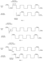
FIG. 2 is a schematic diagram showing interruption for that a low-frequency flashing light in a working state is interrupted by a high-frequency flashing light and the low-frequency flashing light is in a high-level state in an embodiment of the disclosure; -
FIG. 3 is a schematic diagram showing interruption for that a high-frequency flashing light in a working state is interrupted by a low-frequency flashing light and the high-frequency flashing light is in a high-level state in an embodiment of the disclosure; -
FIG. 4 is a schematic diagram showing interruption for that a low-frequency flashing light in a working state is interrupted by a high-frequency flashing light and the low-frequency flashing light is in a low-level state in an embodiment of the disclosure; -
FIG. 5 is a schematic diagram showing interruption for that a low-frequency flashing light in a working state is interrupted by a high-frequency flashing light and the low-frequency flashing light is in a low-level state in another embodiment of the disclosure; -
FIG. 6 is a schematic diagram showing interruption for that a high-frequency flashing light in a working state is interrupted by a low-frequency flashing light and the high-frequency flashing light is in a low-level state in another embodiment of the disclosure; -
FIG. 7 is a schematic diagram showing interruption of different flashing lights in an embodiment of the disclosure; -
FIG. 8 is a schematic diagram showing interruption of different flashing lights in another embodiment of the disclosure; -
FIG. 9 is a schematic diagram showing interruption for that a frequency of a locking flashing light is interrupted by a frequency of an unlocking flashing light in an embodiment of the disclosure; -
FIG. 10 is a schematic structural diagram of an apparatus for controlling a flashing light of a vehicle in an embodiment of the disclosure; and -
FIG. 11 is a schematic diagram of an electronic device in an embodiment of the disclosure. - In the following description, specific details such as specific system structures and technologies are provided for illustrating purposes rather than limitation, to facilitate a thorough understanding of the embodiments of the present application. However, persons skilled in the art should be understood that the present application can also be implemented in other embodiments without these specific details. In other cases, detailed descriptions of well-known systems, devices, circuits, and methods are omitted to avoid unnecessary details hindering the description of the present application.
- In order to clarify the purpose, technical solution, and advantages of the present application, specific embodiments will be described below in conjunction with the accompanying drawings.
-
FIG. 1 is a flow chart showing the achievement of a method for controlling a flashing light of a vehicle in an embodiment of the disclosure. In the prior art, interruption control on a steering light is based on a priority of a request, preferably makes a response to a high-priority request, and even makes no response to a low-priority request, and a phenomenon that flicker frequencies are inconsistent can also be caused during interruption switching, which lowers user experience. In the disclosure, in order to solve the above-mentioned problem, switching is based on a flicker frequency corresponding to a flashing light during interruption control on the flashing light, so that different-priority requests can be equally processed, and the phenomenon that the flicker frequencies are inconsistent after switching is processed. An existing flashing light at least includes four kinds of frequencies, and time corresponding to each light flicker can be 350ms, 200ms, 150ms, and always-on 1s, respectively. - The method for controlling the flashing light of the vehicle is described in detail as follows:
step 101, when a flashing light switching request is received, and a flashing light corresponding to the flashing light switching request and the current flashing light are the same flashing light, acquiring a first flicker frequency and a working state of the current flashing light and a second flicker frequency of the flashing light corresponding to the flashing light switching request; wherein the working state includes an on state and an off state of flicker. - The current flashing light is a flashing light that is in a working state currently and is flickering at a certain frequency for caution, at the moment, when the flashing light switching request is received, it should be distinguished whether the flashing light corresponding to the flashing light switching request and the current flashing light are the same flashing light, and when the both are the same flashing light, for example, they are both left steering lights or right steering lights, interruption processing is performed according to flicker frequencies of the flashing light corresponding to the flashing light switching request and the current flashing light. When the both are different flashing lights, interruption processing different from interruption processing for the same flashing light is adopted for control, which specifically refers to
FIGs. 7 to 9 and corresponding descriptions. The flashing light can be divided into steering lights, a hazard warning light, a locking flashing light, and an unlocking flashing light; wherein the steering lights include a left steering light and a right steering light. - In the present embodiment, first and second in the first flicker frequency and the second flicker frequency are only intended to distinguish different flicker frequencies, rather than to sort the flicker frequencies. Time of the on state or the off state of each flicker corresponding to different flicker frequencies is different, but the time of the on state and time of the off state corresponding to the same flicker frequency are the same, the on state is also referred to as an On state, i.e., a state that a flashing light is turned on, and the off state is also referred to as an Off state, i.e., a state that a flashing light is turned off.
- It should be noted that the on state and the off state can be two different corresponding working states when the flashing light flickers, can be relative concepts, i.e., different brightnesses, for example, the flashing light can be divided into three levels from off to on, the third level is the brightest, the on state can be a third-level state, and the off state is a first-level state. Similarly, the on state can be a second-level state, and the off state is the first-level state, or the on state is the third-level state, and the off state is the second-level state. The flicker of the flashing light can also be controlled by a level, a high level corresponds to the on state, and a low level corresponds to the off state. Herein, the low level is relative to the high level and can be a level slightly lower than the high level.
-
Step 102, determining a switching moment according to the first flicker frequency and the working state of the current flashing light and the second flicker frequency. - In the present embodiment, after the flashing light switching request is received, switching is not directly performed, a switching moment (i.e. an interruption moment) is determined according to the working state and the first flicker frequency and the second flicker frequency of the flashing lights, and switching is performed at the switching moment, so that the problem of nonuniform flicker frequencies caused by interruption in the prior art is solved.
- How to determine the switching moment will be described in detail below with different embodiments.
- In an embodiment, there are two situations for interruption processing when the current flashing light is in the working state and the on state. For a first situation, a low-frequency flashing light in a working state is interrupted by a high-frequency flashing light, and the low-frequency flashing light is in an on state. As shown in
FIG. 2 , the current flashing light under a low-priority flashing light request is in the on state, a flashing light switching request from a high-priority flashing light is received, a frequency of the high-priority flashing light is the second flicker frequency, for example, the time of the on state or the off state of each flicker can be 200ms, and a frequency of a low-priority flashing light is the first flicker frequency, for example, the time of the on state or the off state of each flicker can be 350ms. It should be noted that the priority of the flashing light request is not directly related to the flicker frequency of the flashing light. At that moment, when the working state of the current flashing light is the on state, it can be determined that the switching moment is a moment at which the on state corresponding to the first flicker frequency is ended. With reference toFIG. 2 , the flashing light switching request is received in the on state, for example, the flashing light switching request is received when a duration time of the on state is 100ms, and interruption is performed after the on state lasts for the 350ms. When it is determined that the switching moment is reached, a frequency output of the current flashing light is switched to a second flicker frequency output started in the off state. For such flashing light switching, although the flicker frequencies before and after switching are different, the situation of nonuniform flicker frequencies caused by immediately switching the flashing light to the off state due to interruption after just switching from the off state to the on state in the prior art can be avoided. In the present embodiment, the flicker frequencies of the flashing light before and after switching can be relatively uniform. - It should be noted that a low priority and a high priority that are described herein are relative. Generally, priorities requested in the vehicle can be divided into sixteen priorities from high to low, wherein priority 1 is the highest priority, and priority 16 is the lowest priority.
- Priority 1: thermal runaway alarm, wherein thermal runaway means that a battery in a vehicle is overheated;
- Priority 2: collision alarm;
- Priority 3: backup door mislocking prevention;
- Priority 4: back-row living detection prompt;
- Priority 5: emergency brake light;
- Priority 6: flicker during failure of brake light;
- Priority 7: locking prompt, unlocking indication, and anti-theft fortification;
- Priority 8: anti-theft alarm;
- Priority 9: anti-pinch alarm for window and skylight;
- Priority 10: vehicle finding tips;
- Priority 11: back door open system learning and high learning;
- Priority 12: highway pilot (HWP) system steering light and HWP hazard warning light;
- Priority 13: steering light function (including a steering light and a lane change light), hazard warning light function, and intelligent driving steering light;
- Priority 14: automatic emergency braking and safety braking;
- Priority 15: back-collision prewarning; and
- Priority 16: parking assistance instruction.
- For a second situation, a high-frequency flashing light in a working state is interrupted by a low-frequency flashing light, and the high-frequency flashing light is on a high level. As shown in
FIG. 3 , the current flashing light under a low-priority flashing light request is in the on state, a flicker frequency thereof is the first flicker frequency, for example, the time of the on state or the off state of each flicker can be 150ms, and a flashing light switching request from a high-priority flashing light is received, a frequency thereof is the second flicker frequency, for example, the time of the on state or the off state of each flicker can be 200ms. At the moment, when the working state of the current flashing light is the on state, it can be determined that the switching moment is a moment at which the on state corresponding to the first flicker frequency is ended. That is, the flashing light switching request is received in the on state, for example, the flashing light switching request is received when a duration time of the on state is 50ms, and interruption is performed after the on state lasts for the 150ms. When it is determined that the switching moment is reached, a first flicker frequency output of the current flashing light is switched to a second flicker frequency output of the flashing light corresponding to the flashing light switching request, and the working state of the flashing light corresponding to the flashing light switching request is the off state. - When interruption control is performed on the current flashing light in the working state in the off state, the switching moment needs to be determined according to the flicker frequency and the duration time of the off state of the current flashing light. Optionally, when the working state of the current flashing light is the off state, it is detected whether the second flicker frequency is lower than the first flicker frequency; when the second flicker frequency is lower than the first flicker frequency, it is detected whether a duration time of the off state is shorter than a duration time of the on state corresponding to the second flicker frequency; and when the duration time of the off state is shorter than the duration time of the on state corresponding to the second flicker frequency, it is determined that the switching moment is a corresponding moment at which the duration time of the off state is equal to the duration time of the on state corresponding to the second flicker frequency.
- As shown in
FIG. 4 , a low-frequency flashing light in a working state is interrupted by a high-frequency flashing light, and the low-frequency flashing light is on a low level. The current flashing light in a working state is a low-priority flashing light, a flicker frequency thereof is the first flicker frequency, for example, a duration time of the on state or the off state of each flicker is 350ms; when the low-priority flashing light is in the off state, a flashing light switching request from a high-priority flashing light is received, for example, a duration time of the on state or the off state of each flicker is 200ms, then the second flicker frequency is higher than the first flicker frequency; and when the duration time of the off state is shorter than the duration time of the on state corresponding to the second flicker frequency, as shown inFIG. 4 , the duration time of the off state is 100ms, but does not exceed 200ms, at the moment, it is determined that a moment at which the off state lasts for another 100ms is the switching moment, and thus, switching is performed at a moment when the off state lasts for 200ms, the flashing light is switched from a first flicker frequency output to a second flicker frequency output, and the working state of the flashing light corresponding to the flashing light switching request is the on state. The flicker frequency of the flashing light processed in such a way will not be changed abruptly and is relatively uniform. - Optionally, after the step that it is detected whether a duration time of the off state is shorter than a duration time of the on state corresponding to the second flicker frequency, the method further includes: when the duration time of the off state is longer than or equal to the duration time of the on state corresponding to the second flicker frequency, it is determined that the switching moment is a moment at which the flashing light switching request is received. As shown in
FIG. 5 , such an application scenario is still that a low-frequency flashing light is interrupted by a high-frequency flashing light, which is similar to the situation shown inFIG. 4 except that the duration time of the off state has exceeded 200ms, for example, when having been 300 ms which is the duration time of the off state, the moment at which the flashing light switching request is received is longer than the duration time of the on state corresponding to the second flicker frequency of the flashing light corresponding to the flashing light switching request, at the moment, switching is directly performed. - In an embodiment, a scenario shown in
FIG. 4 and FIG. 5 is that a low-frequency flashing light is interrupted by a high-frequency flashing light. In the present embodiment, a scenario shown inFIG. 6 is that a high-frequency flashing light is interrupted by a low-frequency flashing light. For example, a duration time of the on state or the off state corresponding to the second flicker frequency is 350ms, a duration time of the on state or the off state corresponding to the first flicker frequency is 200ms, a flashing light switching request is received in an off state of the current flashing light in a working state, for example, the flashing light switching request is received at 50ms, in order to keep the flicker frequency relatively uniform, it is determined that the switching moment is a moment at which the off state corresponding to the first flicker frequency is ended, that is, when the off state lasts for 200ms, a first flicker frequency output of the current flashing light is switched to a second flicker frequency output of the flashing light corresponding to the flashing light switching request, and the working state of the flashing light corresponding to the flashing light switching request is the on state. - The method for controlling the flashing light in the case that the flashing light corresponding to the flashing light switching request and the current flashing light are the same flashing light is described in above embodiment, and a corresponding method for controlling a flashing light of a vehicle when the flashing light corresponding to the flashing light switching request and the current flashing light are not the same flashing light is further included.
- In an embodiment, after the flashing light switching request is received, the method in the embodiment of the disclosure can further include: when the flashing light corresponding to the flashing light switching request and the current flashing light are not the same flashing light, after the flashing light switching request is received, the current flashing light is turned off, and the flashing light corresponding to the flashing light switching request is turned on. Thus, it can be ensured that a timely response is made to the flashing light switching request to reduce time delay.
- The flashing light corresponding to the flashing light switching request and the current flashing light are not the same flashing light, which can include that: the flashing light corresponding to the flashing light switching request is a left/right steering light, and the current flashing light is a right/left steering light; the flashing light corresponding to the flashing light switching request is a left/right steering light, and the current flashing light is a hazard warning light; the flashing light corresponding to the flashing light switching request is a hazard warning light, and the current flashing light is a right/left steering light; and the flashing light corresponding to the flashing light switching request is an unlocking light, and the current flashing light is a locking light.
- Under a demand of ensuring the timely response of different flashing lights, in order to ensure that the flicker frequencies are relatively uniform, different switching ways can be adopted according to different working states. Optionally, when the flashing light corresponding to the flashing light switching request and the current flashing light are not the same flashing light, and the working state of the current flashing light is the on state, after the flashing light switching request is received, the current flashing light is turned off, the flashing light corresponding to the flashing light switching request is turned on after output is performed in the off state for a preset time, and the working state of the flashing light corresponding to the flashing light switching request is kept in the on state. The preset time described herein can be set as required, for example, the preset time can be 10ms, 20ms and other durations, which will not be specifically limited herein.
- When the flashing light corresponding to the flashing light switching request and the current flashing light are not the same flashing light, and the working state of the current flashing light is the off state, after the flashing light switching request is received, the current flashing light is turned off, at the same time, the flashing light corresponding to the flashing light switching request is turned on, and the working state of the flashing light corresponding to the flashing light switching request is kept in the on state.
- As shown in
FIG. 7 , when the flashing light corresponding to the flashing light switching request is the left/right steering light, and the current flashing light is the right/left steering light, flicker frequencies thereof are both 350ms; and when the flashing light switching request is received in the on state, the right/left steering light is immediately turned off, the left/right steering light is turned on after keeping in the off state for 10ms, outputting in the on state is performed. - As shown in
FIG. 8 , when the flashing light corresponding to the flashing light switching request is the left/right steering light, and the current flashing light in the working state is the right/left steering light, flicker frequencies thereof are both 350ms; and when the flashing light switching request is received in the off state, the right/left steering light is immediately turned off, at the same time, the left/right steering light is turned on, outputting in the on state is performed. - With reference to
FIG. 7 , when the flashing light corresponding to the flashing light switching request is the left/right steering light, and the current flashing light is the hazard warning light, or the flashing light corresponding to the flashing light switching request is the hazard warning light, and the current flashing light is the left/right steering light, if the flashing light switching request is received in the on state of the current flashing light, the hazard warning light or the left/right steering light is immediately turned off, and frequencies start to be outputted in the on state. - In an embodiment, with reference to
FIG. 8 , when the flashing light corresponding to the flashing light switching request is the left/right steering light, and the current flashing light is the hazard warning light, or the flashing light corresponding to the flashing light switching request is the hazard warning light, and the current flashing light is the left/right steering light, if the flashing light switching request is received in the off state of the current flashing light, the hazard warning light or the left/right steering light is immediately turned off, at the same time, the left/right steering light or the hazard warning light is turned on, and outputting is started in the on state. - In an embodiment, as shown in
FIG. 9 , a flicker duration of the locking flashing light is 1 second (1s), and it is in the off state in other time, for example, a flashing light switching request from the unlocking flashing light is received when the on state lasts for 100ms, and after the off state lasts for a preset time, the off state is immediately switched to the on state, and outputting is performed at a flicker frequency of the unlocking flashing light. -
Step 103, switching a first flicker frequency of the current flashing light to a second flicker frequency of the flashing light corresponding to the flashing light switching request at the switching moment, and the working state of the flashing light corresponding to the flashing light switching request is different from the working state of the current flashing light achieved when the flashing light switching request is received. - A specific description for the present step refers to the description for
step 102 andFIG. 2 to FIG. 9 . - It can be understood that numerical values mentioned in the embodiments of the disclosure are only for the purpose of reference, rather than specific limitations on relative numerical values. During actual applications, other specific numerical values can also be adopted.
- According to the above-mentioned method for controlling the flashing light of the vehicle, when the flashing light corresponding to the flashing light switching request and the current flashing light are the same flashing light, the switching moment is determined according to different working states and the first flicker frequency of the flashing light and the second flicker frequency of the flashing light corresponding to the flashing light switching request, the first flicker frequency of the flashing light is switched to the second flicker frequency at the switching moment, and the working state of the flashing light corresponding to the flashing light switching request is different from the working state of the current flashing light achieved when the flashing light switching request is received, so that flicker frequencies of the flashing light before and after switching can be kept uniform, and a driver and personnel outside the vehicle can know about a real state of the vehicle to reduce traffic accidents. In addition, when the flashing light corresponding to the flashing light switching request and the current flashing light are not the same flashing light, after the flashing light switching request is received, the current flashing light is turned off, and the flashing light corresponding to the flashing light switching request is turned on to perform frequency output, so that it can be ensured that a timely response is made to the flashing light switching request to reduce time delay.
- It should be understood that the serial number of each step in the above-mentioned embodiment does not mean an order of execution. The order of execution of each process should be determined based on functions and internal logics thereof, and should not constitute any limitations on an implementation process of the embodiment of the disclosure.
- An apparatus embodiment of the disclosure is shown below, and details not described in detail therein can refer to the above-mentioned corresponding method embodiment.
-
FIG. 10 shows a schematic structural diagram of an apparatus for controlling a flashing light of a vehicle in an embodiment of the disclosure. For facilitating description, parts related to the embodiments of the disclosure are only shown in detail as follows:
as shown inFIG. 10 , the apparatus for controlling the flashing light of the vehicle includes anacquisition module 1001, a determiningmodule 1002, and aprocessing module 1003. - The
acquisition module 1001 is configured to when a flashing light switching request is received, and a flashing light corresponding to the flashing light switching request and the current flashing light are the same flashing light, acquire a first flicker frequency and a working state of the current flashing light and a second flicker frequency of the flashing light corresponding to the flashing light switching request; wherein the working state includes an on state and an off state of flicker; - the determining
module 1002 is configured to determine a switching moment according to the first flicker frequency and the working state of the current flashing light and the second flicker frequency; and - the
processing module 1003 is configured to switch a first flicker frequency of the current flashing light to a second flicker frequency of the flashing light corresponding to the flashing light switching request at the switching moment, and the working state of the flashing light corresponding to the flashing light switching request is different from the working state of the current flashing light achieved when the flashing light switching request is received. - In a possible implementation, when determining the switching moment according to the first flicker frequency and the working state of the current flashing light and the second flicker frequency, the determining
module 1002 is configured to:
when the working state of the current flashing light is the on state, determine that the switching moment is a moment at which the on state corresponding to the first flicker frequency is ended. - In a possible implementation, when determining the switching moment according to the first flicker frequency and the working state of the current flashing light and the second flicker frequency, the determining
module 1002 is configured to: - when the working state of the current flashing light is the off state, determine whether the second flicker frequency is higher than the first flicker frequency;
- when the second flicker frequency is higher than the first flicker frequency, determine whether a duration time of the off state is shorter than a duration time of the on state corresponding to the second flicker frequency; and
- when the duration time of the off state is shorter than the duration time of the on state corresponding to the second flicker frequency, determine that the switching moment is a corresponding moment at which the duration time of the off state is equal to the duration time of the on state corresponding to the second flicker frequency.
- In a possible implementation, after determining whether a duration time of the off state is shorter than a duration time of the on state corresponding to the second flicker frequency, the determining
module 1002 is further configured to:
when the duration time of the off state is longer than or equal to the duration time of the on state corresponding to the second flicker frequency, determine that the switching moment is a moment at which the flashing light switching request is received. - In a possible implementation, after determining whether the second flicker frequency is higher than the first flicker frequency, the determining
module 1002 is further configured to:
when the second flicker frequency is lower than the first flicker frequency, determine that the switching moment is a moment at which the off state corresponding to the first flicker frequency is ended. - In a possible implementation, the
processing module 1003 is further configured to:
when the flashing light corresponding to the flashing light switching request and the current flashing light are not the same flashing light, after the flashing light switching request is received, turn off the current flashing light, and turn on the flashing light corresponding to the flashing light switching request. - In a possible implementation, when the flashing light corresponding to the flashing light switching request and the current flashing light are not the same flashing light, after the flashing light switching request is received, the current flashing light is turned off, and the flashing light corresponding to the flashing light switching request is turned on, the
processing module 1003 is configured to: - when the flashing light corresponding to the flashing light switching request and the current flashing light are not the same flashing light, and the working state of the current flashing light is the on state, after the flashing light switching request is received, turn off the current flashing light, turn on the flashing light corresponding to the flashing light switching request after staying in the off state for a preset time, and keep the working state of the flashing light corresponding to the flashing light switching request in the on state; and
- when the flashing light corresponding to the flashing light switching request and the current flashing light are not the same flashing light, and the working state of the current flashing light is the off state, after the flashing light switching request is received, turn off the current flashing light, at the same time, turn on the flashing light corresponding to the flashing light switching request, and keep the working state of the flashing light corresponding to the flashing light switching request in the on state.
- It should be noted that technical means and technical effects which are not described in detail in the apparatus embodiment of the disclosure can refer to the corresponding technical means and technical effects in the method embodiment of the disclosure. It should be considered that contents that are not described in detail have been clearly recorded in the device embodiment of the disclosure after the description.
- According to the above-mentioned apparatus for controlling the flashing light of the vehicle, when the flashing light corresponding to the flashing light switching request and the current flashing light in the working state are the same flashing light, the determining module determines the switching moment according to the working state and the first flicker frequency of the flashing light and the second flicker frequency of the flashing light corresponding to the flashing light switching request, the processing module switches the first flicker frequency of the flashing light to the second flicker frequency at the switching moment, and the working state of the flashing light corresponding to the flashing light switching request is different from the working state of the current flashing light achieved when the flashing light switching request is received, so that flicker frequencies of the flashing light before and after switching can be kept uniform, and a driver and personnel outside the vehicle can know about a real state of the vehicle to reduce traffic accidents. In addition, the processing module is further configured to when the flashing light corresponding to the flashing light switching request and the current flashing light are not the same flashing light, after receiving the flashing light switching request, turn off the current flashing light, and turn on the flashing light corresponding to the flashing light switching request, so that it can be ensured that a timely response is made to the flashing light switching request to reduce time delay.
- Another embodiment of the disclosure further provides a vehicle, and the vehicle includes a schematic diagram of an electronic device shown in
FIG. 11 . As shown inFIG. 11 , theelectronic device 11 in the embodiment includes aprocessor 110, amemory 111, and acomputer program 112 stored in thememory 111 and capable of running on theprocessor 110. Theprocessor 110, when executing thecomputer program 112, implements the steps in each of above-mentioned embodiments of the method for controlling the flashing light of the vehicle, such assteps 101 to 103 shown inFIG. 1 . Or, theprocessor 110, when executing thecomputer program 112, implements the function of each module/unit in each of the above-mentioned apparatus embodiments, such as functions of the modules/units 1001 to 1003 shown inFIG. 10 . - Exemplarily, the
computer program 112 can be divided into one or more modules/units, and the one or more modules/units are stored in thememory 111 and are executed by theprocessor 110 so as to complete the disclosure. The one or more modules/units can be a series of computer program instruction segments capable of completing specific functions, and the instruction segments are configured to describe an execution process of thecomputer program 112 in theelectronic device 11. For example, thecomputer program 112 can be divided into the modules/units 1001 to 1003 shown inFIG. 10 . - The
electronic device 11 can be a computing device, such as a desktop computer, a laptop, a handheld computer, and a cloud server. Theelectronic device 11 can include, but is not limited to, theprocessor 110 and thememory 111. It can be understood by the skilled in the art thatFIG. 11 only shows an example of theelectronic device 11, but does not constitute a limitation on theelectronic device 11, and can include more or fewer components than those shown in the figure or combine some components or different components, for example, the electronic device can further include an input/output device, a network access device, a bus, etc. - The
processor 110 can be a Central Processing Unit (CPU) and can also be other general-purpose processors, a Digital Signal Processor (DSP), an Application Specific Integrated Circuit (ASIC), a Field-Programmable Gate Array (FPGA) or other programmable logic devices, a discrete gate or transistor logic device, a discrete hardware component, etc. The general-purpose processor can be a microprocessor or the processor can also be any conventional processor, etc. - The
memory 111 can be an internal storage unit of theelectronic device 11, such as a hard disk or internal memory of theelectronic device 11. Thememory 111 can also be an external storage device of theelectronic device 11, such as a plug-in hard disk, a Smart Media Card (SMC), a Secure Digital (SD) card and a Flash Card that are equipped on theelectronic device 11. Further, thememory 111 can further include both the internal storage unit of theelectronic device 11 and the external storage device. Thememory 111 is configured to store a computer program and other programs and data required by the electronic device. Thememory 111 can be further configured to temporarily store data that has been outputted or is to be outputted. - Persons skilled in the art can clearly understand that, for the sake of convenience and simplicity in description, only the division of the above functional units and modules will be illustrated with examples. In practical applications, the above function allocation can be completed by different functional units or modules as needed, that is, the internal structure of the device can be divided into different functional units or modules to complete all or part of the functions described above. The various functional units and modules in the embodiments can be integrated into one processing unit, or they can exist separately physically, or two or more units can be integrated into one unit. The integrated units mentioned above can be implemented in the form of hardware or software functional units. In addition, the specific names of each functional unit and module are only for the purpose of distinguishing them from each other and are not intended to limit the scope of protection of the present application. The specific working process of the units and modules in the above device can refer to the corresponding process in the embodiments of the aforementioned method, and will not be repeated here.
- In the above embodiments, the descriptions of the embodiments have their own emphasis. For the parts that are not detailed or recorded in one embodiment, please refer to the relevant descriptions of other embodiments.
- Persons skilled in the art can realize that the units and algorithm steps described in the embodiments disclosed in the present application can be implemented through the electronic hardware, or a combination of the computer software and the electronic hardware. Whether these functions are executed in the hardware or the software depends on the specific application and design constraint conditions of the technical solution. Persons skilled in the art can use different methods to achieve the described functions for each specific application, but these implementation methods should not be considered beyond the scope of the present application.
- In the embodiments provided in the present application, it should be understood that the disclosed devices/electronic devices and methods can be implemented in other ways. For example, the embodiments of the device/electronic device described above is only illustrative. For example, the division of the modules or units is only a logical functional division, and there may be other ways of division in actual implementation. For example, multiple units or components can be combined or integrated into another system, or some features can be ignored or not executed. On the other hand, the mutual coupling or direct coupling or communication connection displayed or discussed can be indirect coupling or communication connection through some interfaces, devices or units, which can be electrical, mechanical or other forms.
- The units described as separate components may or may not be physically separated, and the components displayed as units may or may not be physical units. That is, the above components and units can be located in one place or distributed across multiple network units. Some or all of the units can be selected according to actual needs to achieve the goals of various solutions of the embodiments.
- When integrated modules/units are implemented in the form of software functional units and sold or used as independent products, they can be stored in a computer-readable storage medium. Based on the understanding, the present application implements all or part of the processes in the above-mentioned method embodiments, which can be completed by controlling the relevant hardware through the computer programs. The computer program can be stored in a computer-readable storage medium, and when executed by a processor, it can implement the steps of the various acceleration control methods of the vehicle described above. Among them, the computer programs include computer program codes, which can be in the form of source codes, object codes, executable files, or some intermediate forms. The computer-readable medium can include: any entity or device capable of carrying the computer program codes, recording mediums, USB flash drives, portable hard drives, magnetic disks, optical disks, computer memory, read-only memory (ROM), random access memory (RAM), electric carrier signals, telecommunications signals, and software distribution medium. It should be noted that the content contained in the computer-readable medium can be appropriately added or removed according to the requirements of legislation and patent practice within the jurisdiction. For example, in some jurisdictions, according to the legislation and the patent practice, the computer-readable medium do not include the electric carrier signals and the telecommunications signals.
- The above embodiments are merely intended to explain the technical solutions of the present application, and not to limit them. Although the present application is explained in detail with reference to the above embodiments, a person skilled in the art should understand that he can still modify the technical solutions set forth by the above embodiments, or make equivalent substitutions to part of the technical features of them. However, those modifications or substitutions do not make the essence of the corresponding technical solutions depart from the spirit and scope of the technical solutions of the embodiments of the present application.
Claims (16)
- A method for controlling a flashing light of a vehicle, characterized by comprising:when a flashing light switching request is received, and a flashing light corresponding to the flashing light switching request and the current flashing light are the same flashing light, acquiring a first flicker frequency and a working state of the current flashing light and a second flicker frequency of the flashing light corresponding to the flashing light switching request; wherein the working state comprises an on state and an off state of flicker;determining a switching moment according to the first flicker frequency and the working state of the current flashing light and the second flicker frequency; andswitching a first flicker frequency of the current flashing light to a second flicker frequency of the flashing light corresponding to the flashing light switching request at the switching moment, and the working state of the flashing light corresponding to the flashing light switching request is different from the working state of the current flashing light achieved when the flashing light switching request is received.
- The method for controlling the flashing light of the vehicle according to claim 1, characterized in that, the step of determining a switching moment according to the first flicker frequency and the working state of the current flashing light and the second flicker frequency comprises:
when the working state of the current flashing light is the on state, determining that the switching moment is a moment when the on state corresponding to the first flicker frequency is ended. - The method for controlling the flashing light of the vehicle according to claim 1, characterized in that, the step of determining a switching moment according to the first flicker frequency and the working state of the current flashing light and the second flicker frequency comprises:when the working state of the current flashing light is the off state, determining whether the second flicker frequency is higher than the first flicker frequency;when the second flicker frequency is higher than the first flicker frequency, determining whether a duration time of the off state is shorter than a duration time of the on state corresponding to the second flicker frequency; andwhen the duration time of the off state is shorter than the duration time of the on state corresponding to the second flicker frequency, determining that the switching moment is a moment at which the duration time of the off state is equal to the duration time of the on state corresponding to the second flicker frequency.
- The method for controlling the flashing light of the vehicle according to claim 3, characterized in that, after the step of determining whether a duration time of the off state is shorter than a duration time of the on state corresponding to the second flicker frequency, the method further comprises:
when the duration time of the off state is longer than or equal to the duration time of the on state corresponding to the second flicker frequency, determining that the switching moment is a moment at which the flashing light switching request is received. - The method for controlling the flashing light of the vehicle according to claim 3, characterized in that, after the step of determining whether the second flicker frequency is higher than the first flicker frequency, the method further comprises:
when the second flicker frequency is lower than the first flicker frequency, determining that the switching moment is a moment at which the off state corresponding to the first flicker frequency is ended. - The method for controlling the flashing light of the vehicle according to any one of claims 1 to 5, characterized in that, after the flashing light switching request is received, the method further comprises:
when the flashing light corresponding to the flashing light switching request and the current flashing light are not the same flashing light, after the flashing light switching request is received, turning off the current flashing light, and turning on the flashing light corresponding to the flashing light switching request. - The method for controlling the flashing light of the vehicle according to claim 6, characterized in that, the step of when the flashing light corresponding to the flashing light switching request and the current flashing light are not the same flashing light, after the flashing light switching request is received, turning off the current flashing light, and turning on the flashing light corresponding to the flashing light switching request comprises:when the flashing light corresponding to the flashing light switching request and the current flashing light are not the same flashing light, and the working state of the current flashing light is the on state, after the flashing light switching request is received, turning off the current flashing light, turning on the flashing light corresponding to the flashing light switching request after staying in the off state for a preset time, and keeping the working state of the flashing light corresponding to the flashing light switching request in the on state; andwhen the flashing light corresponding to the flashing light switching request and the current flashing light are not the same flashing light, and the working state of the current flashing light is the off state, after the flashing light switching request is received, turning off the current flashing light, at the same time, turning on the flashing light corresponding to the flashing light switching request, and keeping the working state of the flashing light corresponding to the flashing light switching request in the on state.
- An apparatus for controlling a flashing light of a vehicle, characterized by comprising:an acquisition module configured to when a flashing light switching request is received, and a flashing light corresponding to the flashing light switching request and the current flashing light are the same flashing light, acquire a first flicker frequency and a working state of the current flashing light and a second flicker frequency of the flashing light corresponding to the flashing light switching request; wherein the working state comprises an on state and an off state of flicker;a determining module configured to determine a switching moment according to the first flicker frequency and the working state of the current flashing light and the second flicker frequency; anda processing module configured to switch a first flicker frequency of the current flashing light to a second flicker frequency of the flashing light corresponding to the flashing light switching request at the switching moment, and the working state of the flashing light corresponding to the flashing light switching request is different from the working state of the current flashing light achieved when the flashing light switching request is received.
- The apparatus for controlling the flashing light of the vehicle according to claim 8, characterized in that, the determining module is configured to:
when the working state of the current flashing light is the on state, determine that the switching moment is a moment at which the on state corresponding to the first flicker frequency is ended. - The apparatus for controlling the flashing light of the vehicle according to claim 8, characterized in that, the determining module is configured to:when the working state of the current flashing light is the off state, determine whether the second flicker frequency is higher than the first flicker frequency;when the second flicker frequency is higher than the first flicker frequency, determine whether a duration time of the off state is shorter than a duration time of the on state corresponding to the second flicker frequency; andwhen the duration time of the off state is shorter than the duration time of the on state corresponding to the second flicker frequency, determine that the switching moment is a moment at which the duration time of the off state is equal to the duration time of the on state corresponding to the second flicker frequency.
- The apparatus for controlling the flashing light of the vehicle according to claim 10, characterized in that, the determining module is further configured to:
when the duration time of the off state is longer than or equal to the duration time of the on state corresponding to the second flicker frequency, determine that the switching moment is a moment at which the flashing light switching request is received. - The apparatus for controlling the flashing light of the vehicle according to claim 10, characterized in that, the determining module is further configured to:
when the second flicker frequency is lower than the first flicker frequency, determine that the switching moment is a moment at which the off state corresponding to the first flicker frequency is ended. - The apparatus for controlling the flashing light of the vehicle according to any one of claims 8 to 12, characterized in that, the processing module is further configured to:
when the flashing light corresponding to the flashing light switching request and the current flashing light are not the same flashing light, after the flashing light switching request is received, turn off the current flashing light, and turn on the flashing light corresponding to the flashing light switching request. - The apparatus for controlling the flashing light of the vehicle according to claim 13, characterized in that, the processing module is configured to:when the flashing light corresponding to the flashing light switching request and the current flashing light are not the same flashing light, and the working state of the current flashing light is the on state, after the flashing light switching request is received, turn off the current flashing light, turn on the flashing light corresponding to the flashing light switching request after staying in the off state for a preset time, and keep the working state of the flashing light corresponding to the flashing light switching request in the on state; andwhen the flashing light corresponding to the flashing light switching request and the current flashing light are not the same flashing light, and the working state of the current flashing light is the off state, after the flashing light switching request is received, turn off the current flashing light, at the same time, turn on the flashing light corresponding to the flashing light switching request, and keep the working state of the flashing light corresponding to the flashing light switching request in the on state.
- A vehicle comprising an electronic device, wherein the electronic device includes a memory, a processor, and a computer program stored in the memory and capable of running on the processor, characterized in that, the processor, when executing the computer program, implements the steps of the method for controlling the flashing light of the vehicle according to any one of claims 1 to 7.
- A nonvolatile computer-readable storage medium, having a computer program stored thereon, characterized in that, the computer program, when executed by a processor, implements the steps of the method for controlling the flashing light of the vehicle according to any one of claims 1 to 7.
Applications Claiming Priority (2)
| Application Number | Priority Date | Filing Date | Title |
|---|---|---|---|
| CN202111602387.4A CN115107637B (en) | 2021-12-24 | 2021-12-24 | Vehicle flashing light control method, device, vehicle and storage medium |
| PCT/CN2022/138571 WO2023116499A1 (en) | 2021-12-24 | 2022-12-13 | Vehicle flashing light control method and apparatus, vehicle and storage medium |
Publications (3)
| Publication Number | Publication Date |
|---|---|
| EP4454949A1 true EP4454949A1 (en) | 2024-10-30 |
| EP4454949A4 EP4454949A4 (en) | 2025-03-05 |
| EP4454949B1 EP4454949B1 (en) | 2026-02-11 |
Family
ID=83325163
Family Applications (1)
| Application Number | Title | Priority Date | Filing Date |
|---|---|---|---|
| EP22909813.2A Active EP4454949B1 (en) | 2021-12-24 | 2022-12-13 | Vehicle flashing light control method and apparatus, vehicle and storage medium |
Country Status (3)
| Country | Link |
|---|---|
| EP (1) | EP4454949B1 (en) |
| CN (1) | CN115107637B (en) |
| WO (1) | WO2023116499A1 (en) |
Families Citing this family (2)
| Publication number | Priority date | Publication date | Assignee | Title |
|---|---|---|---|---|
| CN115107637B (en) * | 2021-12-24 | 2025-08-29 | 长城汽车股份有限公司 | Vehicle flashing light control method, device, vehicle and storage medium |
| CN118991601B (en) * | 2024-08-05 | 2026-01-09 | 广州汽车集团股份有限公司 | Vehicle lighting control methods, devices, vehicles and storage media |
Family Cites Families (19)
| Publication number | Priority date | Publication date | Assignee | Title |
|---|---|---|---|---|
| JPS58202124A (en) * | 1982-05-21 | 1983-11-25 | Nissan Motor Co Ltd | Flashing device for vehicle |
| CN2196568Y (en) * | 1994-04-29 | 1995-05-10 | 张守善 | Light-signal generator for automobile |
| KR100495735B1 (en) * | 1996-05-29 | 2005-09-02 | 나이루스 가부시키가이샤 | Integrated circuit for direction indicator lamp blinker |
| CN1883982B (en) * | 2005-06-24 | 2010-09-01 | 龚立新 | A vehicle status signal system |
| US7559678B2 (en) * | 2007-06-28 | 2009-07-14 | Tsai Tsung Hsun | Automatic warning light control device for automobiles |
| JP4983941B2 (en) * | 2010-03-02 | 2012-07-25 | 株式会社デンソー | Energization control device |
| CN202144226U (en) * | 2011-08-02 | 2012-02-15 | 蒋浩然 | Slow and emergency braking light warning device |
| US8866386B2 (en) * | 2011-10-31 | 2014-10-21 | Shindengen Electric Manufacturing Co., Ltd. | Direction indication lamp control device, direction indication device and wire disconnection detection method of the direction indication device |
| JP6220184B2 (en) * | 2013-08-09 | 2017-10-25 | 矢崎総業株式会社 | Lamp unit controller |
| JP6800581B2 (en) * | 2015-12-28 | 2020-12-16 | 株式会社小糸製作所 | Lighting circuit, turn signal lamp for vehicles |
| CN106926774A (en) * | 2017-03-10 | 2017-07-07 | 东风汽车公司 | The rear triggering method for controlling priority of vehicle risk alarm lamp and steering indicating light |
| CN108156716B (en) * | 2018-01-29 | 2024-03-19 | 宗仁科技(平潭)股份有限公司 | Control circuit, method and device for flashing back multiple LED lamps |
| CN110562126A (en) * | 2018-05-16 | 2019-12-13 | 上海博泰悦臻电子设备制造有限公司 | Vehicle external atmosphere lamp system |
| CN109017789B (en) * | 2018-08-09 | 2020-12-25 | 北京智行者科技有限公司 | Vehicle control method |
| CN110884422A (en) * | 2018-09-07 | 2020-03-17 | 韩晓云 | Vehicle steering lamp system, control method and automobile |
| TWI688496B (en) * | 2019-03-11 | 2020-03-21 | 黃美惠 | Controlling and operating mode switching method of additional lamps of vehicles |
| EP3838672B1 (en) * | 2019-12-18 | 2022-06-08 | Hyundai Motor Company | Autonomous vehicle and method for controlling it |
| JP7421958B2 (en) * | 2020-03-02 | 2024-01-25 | ローム株式会社 | drive device |
| CN115107637B (en) * | 2021-12-24 | 2025-08-29 | 长城汽车股份有限公司 | Vehicle flashing light control method, device, vehicle and storage medium |
-
2021
- 2021-12-24 CN CN202111602387.4A patent/CN115107637B/en active Active
-
2022
- 2022-12-13 EP EP22909813.2A patent/EP4454949B1/en active Active
- 2022-12-13 WO PCT/CN2022/138571 patent/WO2023116499A1/en not_active Ceased
Also Published As
| Publication number | Publication date |
|---|---|
| WO2023116499A1 (en) | 2023-06-29 |
| EP4454949A4 (en) | 2025-03-05 |
| CN115107637B (en) | 2025-08-29 |
| CN115107637A (en) | 2022-09-27 |
| EP4454949B1 (en) | 2026-02-11 |
Similar Documents
| Publication | Publication Date | Title |
|---|---|---|
| US20220219689A1 (en) | Adaptive cruise control system and adaptive cruise control method supporting traffic light recognition | |
| EP4454949A1 (en) | Vehicle flashing light control method and apparatus, vehicle and storage medium | |
| EP4458632A1 (en) | Driving mode switching method and device, and vehicle | |
| CN112298208A (en) | Automatic driving transverse auxiliary control method and transverse auxiliary system | |
| CN114655252A (en) | Vehicle control method, device, equipment and medium | |
| CN112937559A (en) | Driving warning method and vehicle-mounted device | |
| CN114132329B (en) | Driver attention maintaining method and system | |
| US20250256730A1 (en) | Driving mode control method and system, controller, and vehicle | |
| CN118306380B (en) | Automatic parking method, device, electronic equipment and storage medium | |
| CN117533352A (en) | Auxiliary driving control method and system integrating lamp language information | |
| CN118790140A (en) | Turn signal priority control method, device, vehicle and storage medium | |
| CN114454812A (en) | Vehicle danger warning lamp control method and device and vehicle | |
| CN117727156A (en) | Motor vehicle fatigue driving detection method, device and computer-readable storage medium | |
| CN116386372A (en) | Traffic signal control method, device and storage medium | |
| CN115593426A (en) | Control method, system, equipment and storage medium for vehicle power failure | |
| CN119218223B (en) | Lateral control methods, devices, vehicles and storage media for driver assistance | |
| US20060220819A1 (en) | Method for intelligent crescendo system | |
| CN110111595A (en) | Spare traffic signal control system and method | |
| CN118928435B (en) | Driving function execution method, device, vehicle, storage medium and program product | |
| CN115586907B (en) | Program updating method, program updating device and electronic equipment | |
| CN121157906A (en) | Vehicle control method and program product | |
| CN118753256A (en) | Vehicle brake control method, device, system and medium | |
| CN108323164A (en) | Method, system and the motor vehicle for preventing driver's doze for motor vehicle | |
| CN118068678A (en) | Remote control parking control method and device, vehicle and storage medium | |
| CN116587848A (en) | Vehicle gear control method and device, electronic equipment, storage medium and vehicle |
Legal Events
| Date | Code | Title | Description |
|---|---|---|---|
| STAA | Information on the status of an ep patent application or granted ep patent |
Free format text: STATUS: THE INTERNATIONAL PUBLICATION HAS BEEN MADE |
|
| PUAI | Public reference made under article 153(3) epc to a published international application that has entered the european phase |
Free format text: ORIGINAL CODE: 0009012 |
|
| STAA | Information on the status of an ep patent application or granted ep patent |
Free format text: STATUS: REQUEST FOR EXAMINATION WAS MADE |
|
| 17P | Request for examination filed |
Effective date: 20240722 |
|
| AK | Designated contracting states |
Kind code of ref document: A1 Designated state(s): AL AT BE BG CH CY CZ DE DK EE ES FI FR GB GR HR HU IE IS IT LI LT LU LV MC ME MK MT NL NO PL PT RO RS SE SI SK SM TR |
|
| A4 | Supplementary search report drawn up and despatched |
Effective date: 20250130 |
|
| RIC1 | Information provided on ipc code assigned before grant |
Ipc: B60Q 1/34 20060101ALI20250124BHEP Ipc: B60Q 1/46 20060101AFI20250124BHEP |
|
| DAV | Request for validation of the european patent (deleted) | ||
| DAX | Request for extension of the european patent (deleted) | ||
| GRAP | Despatch of communication of intention to grant a patent |
Free format text: ORIGINAL CODE: EPIDOSNIGR1 |
|
| STAA | Information on the status of an ep patent application or granted ep patent |
Free format text: STATUS: GRANT OF PATENT IS INTENDED |
|
| INTG | Intention to grant announced |
Effective date: 20251013 |
|
| GRAS | Grant fee paid |
Free format text: ORIGINAL CODE: EPIDOSNIGR3 |
|
| GRAA | (expected) grant |
Free format text: ORIGINAL CODE: 0009210 |
|
| STAA | Information on the status of an ep patent application or granted ep patent |
Free format text: STATUS: THE PATENT HAS BEEN GRANTED |
|
| AK | Designated contracting states |
Kind code of ref document: B1 Designated state(s): AL AT BE BG CH CY CZ DE DK EE ES FI FR GB GR HR HU IE IS IT LI LT LU LV MC ME MK MT NL NO PL PT RO RS SE SI SK SM TR |
|
| REG | Reference to a national code |
Ref country code: CH Ref legal event code: F10 Free format text: ST27 STATUS EVENT CODE: U-0-0-F10-F00 (AS PROVIDED BY THE NATIONAL OFFICE) Effective date: 20260211 Ref country code: GB Ref legal event code: FG4D |
|
| REG | Reference to a national code |
Ref country code: DE Ref legal event code: R096 Ref document number: 602022030368 Country of ref document: DE |
|
| REG | Reference to a national code |
Ref country code: IE Ref legal event code: FG4D |
|
| P01 | Opt-out of the competence of the unified patent court (upc) registered |
Free format text: CASE NUMBER: UPC_APP_0006144_4454949/2026 Effective date: 20260219 |