EP4454919A1 - Improved electric traction wheel hub - Google Patents
Improved electric traction wheel hub Download PDFInfo
- Publication number
- EP4454919A1 EP4454919A1 EP24171836.0A EP24171836A EP4454919A1 EP 4454919 A1 EP4454919 A1 EP 4454919A1 EP 24171836 A EP24171836 A EP 24171836A EP 4454919 A1 EP4454919 A1 EP 4454919A1
- Authority
- EP
- European Patent Office
- Prior art keywords
- wheel hub
- axle
- rotor
- fixed portion
- vehicle
- Prior art date
- Legal status (The legal status is an assumption and is not a legal conclusion. Google has not performed a legal analysis and makes no representation as to the accuracy of the status listed.)
- Granted
Links
Images


Classifications
-
- B—PERFORMING OPERATIONS; TRANSPORTING
- B60—VEHICLES IN GENERAL
- B60K—ARRANGEMENT OR MOUNTING OF PROPULSION UNITS OR OF TRANSMISSIONS IN VEHICLES; ARRANGEMENT OR MOUNTING OF PLURAL DIVERSE PRIME-MOVERS IN VEHICLES; AUXILIARY DRIVES FOR VEHICLES; INSTRUMENTATION OR DASHBOARDS FOR VEHICLES; ARRANGEMENTS IN CONNECTION WITH COOLING, AIR INTAKE, GAS EXHAUST OR FUEL SUPPLY OF PROPULSION UNITS IN VEHICLES
- B60K7/00—Disposition of motor in, or adjacent to, traction wheel
- B60K7/0007—Disposition of motor in, or adjacent to, traction wheel the motor being electric
-
- B—PERFORMING OPERATIONS; TRANSPORTING
- B60—VEHICLES IN GENERAL
- B60K—ARRANGEMENT OR MOUNTING OF PROPULSION UNITS OR OF TRANSMISSIONS IN VEHICLES; ARRANGEMENT OR MOUNTING OF PLURAL DIVERSE PRIME-MOVERS IN VEHICLES; AUXILIARY DRIVES FOR VEHICLES; INSTRUMENTATION OR DASHBOARDS FOR VEHICLES; ARRANGEMENTS IN CONNECTION WITH COOLING, AIR INTAKE, GAS EXHAUST OR FUEL SUPPLY OF PROPULSION UNITS IN VEHICLES
- B60K1/00—Arrangement or mounting of electrical propulsion units
- B60K1/02—Arrangement or mounting of electrical propulsion units comprising more than one electric motor
-
- B—PERFORMING OPERATIONS; TRANSPORTING
- B60—VEHICLES IN GENERAL
- B60K—ARRANGEMENT OR MOUNTING OF PROPULSION UNITS OR OF TRANSMISSIONS IN VEHICLES; ARRANGEMENT OR MOUNTING OF PLURAL DIVERSE PRIME-MOVERS IN VEHICLES; AUXILIARY DRIVES FOR VEHICLES; INSTRUMENTATION OR DASHBOARDS FOR VEHICLES; ARRANGEMENTS IN CONNECTION WITH COOLING, AIR INTAKE, GAS EXHAUST OR FUEL SUPPLY OF PROPULSION UNITS IN VEHICLES
- B60K17/00—Arrangement or mounting of transmissions in vehicles
- B60K17/04—Arrangement or mounting of transmissions in vehicles characterised by arrangement, location or kind of gearing
- B60K17/043—Transmission unit disposed in on near the vehicle wheel, or between the differential gear unit and the wheel
- B60K17/046—Transmission unit disposed in on near the vehicle wheel, or between the differential gear unit and the wheel with planetary gearing having orbital motion
-
- B—PERFORMING OPERATIONS; TRANSPORTING
- B60—VEHICLES IN GENERAL
- B60K—ARRANGEMENT OR MOUNTING OF PROPULSION UNITS OR OF TRANSMISSIONS IN VEHICLES; ARRANGEMENT OR MOUNTING OF PLURAL DIVERSE PRIME-MOVERS IN VEHICLES; AUXILIARY DRIVES FOR VEHICLES; INSTRUMENTATION OR DASHBOARDS FOR VEHICLES; ARRANGEMENTS IN CONNECTION WITH COOLING, AIR INTAKE, GAS EXHAUST OR FUEL SUPPLY OF PROPULSION UNITS IN VEHICLES
- B60K1/00—Arrangement or mounting of electrical propulsion units
- B60K2001/003—Arrangement or mounting of electrical propulsion units with means for cooling the electrical propulsion units
-
- B—PERFORMING OPERATIONS; TRANSPORTING
- B60—VEHICLES IN GENERAL
- B60K—ARRANGEMENT OR MOUNTING OF PROPULSION UNITS OR OF TRANSMISSIONS IN VEHICLES; ARRANGEMENT OR MOUNTING OF PLURAL DIVERSE PRIME-MOVERS IN VEHICLES; AUXILIARY DRIVES FOR VEHICLES; INSTRUMENTATION OR DASHBOARDS FOR VEHICLES; ARRANGEMENTS IN CONNECTION WITH COOLING, AIR INTAKE, GAS EXHAUST OR FUEL SUPPLY OF PROPULSION UNITS IN VEHICLES
- B60K7/00—Disposition of motor in, or adjacent to, traction wheel
- B60K2007/0038—Disposition of motor in, or adjacent to, traction wheel the motor moving together with the wheel axle
-
- B—PERFORMING OPERATIONS; TRANSPORTING
- B60—VEHICLES IN GENERAL
- B60Y—INDEXING SCHEME RELATING TO ASPECTS CROSS-CUTTING VEHICLE TECHNOLOGY
- B60Y2200/00—Type of vehicle
- B60Y2200/10—Road Vehicles
- B60Y2200/14—Trucks; Load vehicles, Busses
-
- B—PERFORMING OPERATIONS; TRANSPORTING
- B60—VEHICLES IN GENERAL
- B60Y—INDEXING SCHEME RELATING TO ASPECTS CROSS-CUTTING VEHICLE TECHNOLOGY
- B60Y2400/00—Special features of vehicle units
- B60Y2400/70—Gearings
- B60Y2400/73—Planetary gearings
Definitions
- the present invention relates to a wheel hub for a vehicle axle, in particular a wheel hub with integrated electric traction for an axle of a heavy-duty vehicle.
- Heavy-duty vehicles such as road transport vehicles, for example lorries, tend to be increasingly electrified to reduce their pollutant emissions.
- road transport vehicles for example lorries
- such vehicles may be hybrid vehicles or pure electric vehicles.
- electric vehicles comprise at least one electric axle, i.e. an axle equipped with electric machines such as motors/generators configured to give torque to the wheel hubs to allow them to move or to recharge the vehicle's battery modules when the vehicle is braking.
- electric machines such as motors/generators configured to give torque to the wheel hubs to allow them to move or to recharge the vehicle's battery modules when the vehicle is braking.
- the object of the present invention is to meet the above needs in an optimized and cost-effective manner.
- the reference numeral 1 indicates, as a whole, an axle of a vehicle, preferably a heavy-duty vehicle, e.g. a lorry, not shown, essentially comprising a central portion 2 and a pair of end portions 3, 4 connected on opposite sides to the central portion 2, preferably in a rigid manner, along a longitudinal axis A of the same.
- a heavy-duty vehicle e.g. a lorry
- the central portion 2 is advantageously hollow so as to define a space 5 suitable for housing functional elements of the vehicle as described below.
- the end portions 3, 4 are also hollow so as to define a continuous space 5 along the entire extension of the axle 1 along the axis A.
- the end portions 3, 4 have openings 6 configured to allow access to the space 5 as described below.
- the axle 1 comprises at least one flange 7 arranged in the vicinity of each of the end portions 3, 4 and rigidly carried by them or, as in the case shown, by the central portion 2 and configured to support operating elements of the vehicle, such as, for example, mechanical brakes or sensor means.
- the axle 1 comprises a pair of wheel hubs 10 comprising a fixed portion 8 rigidly carried by the respective end portion 3, 4 and a movable portion 9 carried in a rotationally free manner by the respective end portion 3, 4.
- wheel hubs 10 for simplicity, reference will only be made to one of them, for example the left-hand one, and the following considerations apply equally to the right-hand wheel hub, of course, the structure described herein being mirrored in relation to a longitudinal plane of the vehicle.
- the fixed portion 8 is advantageously cup-shaped and comprises a radial wall 8' connected to the end of the end portion 4 and extending perpendicular to the longitudinal axis A, and a cylindrical wall 8" extending from the radial wall 8' towards the vehicle, i.e., towards the intermediate portion 2 of the axle 1.
- the radial wall 8' is advantageously connected to the end of the end portion 4 via a rigid connection, such as an interference fit connection.
- a rigid connection such as an interference fit connection.
- the radial wall 8' is made in one piece with the cylindrical wall 8''.
- the cylindrical wall 8" is supported, on the side opposite the radial wall 8' with respect to the movable portion 9, in a rotationally free manner by support means 11 such as rolling bearings.
- the cylindrical wall 8'' cooperates with the support means 11 via a support element 12 rigidly connected to the cylindrical wall 8'' and extending radially towards the aforementioned support means 11.
- the cylindrical wall 8'' cooperates, as described above, with the movable portion 9 in a sealed manner via sealing means 13, such as rotating sealing rings, so as to delimit a space 14 isolated from the external environment, radially delimited around the axis A by the cylindrical wall 8", and axially delimited by the radial wall 8' and the movable portion 9.
- sealing means 13 such as rotating sealing rings
- the wheel hub 10 comprises, housed in the space 14, an electric machine 15 equipped with a stator 15' and a rotor 15" operatively driven by the stator 15', and a transmission 16 operatively connecting the rotor 15" to the movable portion 9 so as to vary the transmitted speed/torque compared to that originally supplied to the rotor 15".
- stator 15' is rigidly carried by the fixed portion 8, in particular by the cylindrical wall 8'' and thus extends along the axis A within the space 14.
- the transmission 16 is advantageously sized so as to be radially housed within the rotor 15'' and particularly also axially included by the rotor 15".
- the rotor 15" is connected to a rotor support 17 carried in a rotationally free manner with respect to the fixed portion 8, in particular with respect to the radial wall 8', i.e., to a flanged portion extending with respect thereto.
- the rotor support 17 extends radially inside the rotor 15 and essentially has the shape of an annular disc housed around the end portion 4.
- the rotor support 17 is operatively connected via the transmission 16 to the movable portion 9.
- the transmission 16 comprises a gear train, advantageously a differential gear train.
- the transmission 16 comprises a first bevel gear wheel 21 rigidly connected to the rotor support 17 and rotationally free in relation to the end 4, a second bevel gear wheel 22 rigidly carried by the end 4, and a plurality of satellites 23 operatively cooperating with the first and second bevel gear wheels 21, 22.
- the satellites 23 can be of various numbers and are supported in a rotationally free manner in relation to the plane of axis B perpendicular to the axis A via respective pins 24.
- Each pin 23 is rigidly carried by a carrier 25 rigidly connected to the movable portion 9.
- the transmission 16 is provided with sealing means 13, e.g., carried between the first gear wheel 21 and the end 4, further configured to isolate the space 14.
- the space 14 can be supplied with lubricating fluid, such as oil, via a port 26, for example carried by the rotating portion 9, in order to lubricate the transmission 16.
- lubricating fluid such as oil
- the movable portion 9, as mentioned above, is supported in a rotationally free manner by support means 12, such as rolling bearings, at the end 4.
- the embodiment described comprises a main movable portion 9' and an auxiliary movable portion 9" rigidly connected to each other.
- the main movable portion 9' essentially comprises a main portion 9a, preferably an annular disc, cooperating with the aforementioned support means 12, and a first flanged portion 9b extending axially cantilevered along the axis A in relation to the main portion 9a and rigidly connected to the carrier 25. Accordingly, the first flanged portion 9b extends radially inside the rotor 15".
- the main movable portion 9' comprises a second flanged portion 9c radially extending from the main portion 9a and rigidly connected to a rim 30 as described in detail below.
- the auxiliary movable portion 9" extends from the side opposite the fixed portion 8 and is configured to provide support for operating elements of the vehicle, such as sensors or other elements that need to be integral with the movable portion 9.
- the wheel hub 10 also comprises a conditioning system 40 configured to cool the fixed portion 8, i.e., the stator 15' connected to it.
- the conditioning system 40 is a fluid conditioning system.
- the conditioning system 40 comprises a plurality of ducts 41 in which a conditioning fluid flows and which are adjacent to the stator 15'.
- these ducts 41 are integrated into the fixed portion 8, i.e. the cylindrical portion 8''.
- these ducts 41 are made as grooves 42 defined radially recessed with respect to the surface opposite the space 14 of the cylindrical portion 8" and isolated from the external environment by a cover 43 rigidly carried on the cylindrical portion in a sealed manner, in order to delimit these ducts 41.
- the ducts 41 are fluidically connected to a delivery pipe 44 and a return pipe 45 configured to supply the low temperature conditioning fluid and collect the high temperature conditioning fluid once it has flowed through the ducts 41 to cool the fixed portion 8.
- the ducts 41 are substantially circumferential around the axis A and advantageously of square cross-section. In particular, they have the same size and are equally spaced along the axis A.
- the ducts 41 are fluidically connected to the delivery pipe 44 and the return pipe 45 via respective manifolds 46, which are advantageously integrated into the fixed portion 8, i.e. the cylindrical portion 8''.
- these manifolds 46 are made as a single groove 47 defined radially recessed with respect to the surface opposite the space 14 of the cylindrical portion 8'' and isolated from the external environment by the same cover 43 delimiting the ducts 41.
- the groove 47 extends along the axis A throughout the length of the cylindrical portion 8" in which the ducts 41 are made so that it can fluidically communicate with each of the latter.
- the delivery and return pipes 44, 45 are fluidically connected to a heat exchanger system (not shown) of the vehicle such as, for example, a passive exchanger such as an air radiator, or an active device such as a coolant conditioning circuit.
- a heat exchanger system not shown
- a passive exchanger such as an air radiator
- an active device such as a coolant conditioning circuit.
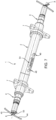
- the delivery pipes 44, 45 are housed within the space 5 and extend between respective fluidic connectors 48, as shown in Figure 7 , which are configured to allow connection to additional pipes (not shown) connecting to the aforementioned heat exchanger of the vehicle.
- the fluidic connectors 48 are made in the central portion 2 of the axle 1.
- the delivery pipes 44, 45 exit the space 5 through the opening 6 and are directed to connect to the manifolds 46 within a space 51 delimited between the fixed portion 8 and a head element 52 connected to it.
- this space 51 is radially delimited by the fixed portion 8, in particular by a flange extending between the cylindrical portion 8'' and the radial portion 8' on the side opposite the cylindrical portion 8'', and axially delimited by the head element 52 and the radial portion 8'.
- the head element 52 in the embodiment shown, is rigidly connected to the cover 43.
- the head element 52 in the embodiment shown, is rigidly connected to the cover 43.
- it could be made in one piece with it.
- the wheel hub 10 further comprises cables 53 for the electrical connection of the electric machine 15 to electric power storage means (not shown) such as the battery, of the vehicle.
- the cables 53 are housed within the space 5 and extend between respective electrical connectors 54, as shown in Figure 7 , which are configured to allow connection to additional cables (not shown) connecting to the aforementioned electric power storage means.
- the electrical connectors 54 are made in the central portion 2 of the axle 1.
- the cables 43 exit the space 5 through the opening 6 into the aforementioned space 51 and pass through a dedicated sealed opening into the space 14, towards the stator 15' of the electric machine 15.
- rim 31 configured to cooperate with a vehicle tire, and a disc 32, which are rigidly connected to each other, for example by welding, as known per se.
- the disc 32 is shaped so as to allow the wheel hub 10 to be housed inside it.
- the disc 32 comprises a coupling portion 33, advantageously comprising an annular disc, and a structural portion 34 configured to provide adequate stiffness to the rim 30 and allow connection to the rim 31.
- the structural portion 34 is rigidly connected at a connecting portion thereof 34', opposite the one connected at the coupling portion 33, to the rim 31, i.e. to an inner radial surface thereof 31'.
- the structural portion 34 is inclined along the axis A and is shaped like a substantially frusto-conical annular disc so as to have a larger opening diameter at the rim 31 and a smaller opening diameter 35 at the coupling portion 33.
- the structural portion 34 is inclined between the larger opening diameter and the smaller opening diameter 35 by a value between 15° and 25°, in particular 20°.
- the inclination provided allows a smaller opening diameter 35 of at least 400 mm to be obtained.
- the structural portion 34 has a corrugated profile, preferably made circumferentially to the axis A.
- this corrugated profile comprises a plurality of grooves 36 made parallel to the axis A and alternating with each other by a plurality of projections 37.
- the grooves 36 have a substantially curved cross-section, advantageously concave towards the rim 31.
- the projections 37 define a substantially flat surface with a constant cross-section between the connecting portion 34' and the coupling portion 33.
- both the grooves 36 and the projections 37 each have the same shape as each other. In this way, preferably, they can be angularly equidistant around the axis A.
- the coupling portion 33 is substantially flat and defines a plurality of openings 38, which are advantageously circumferentially equidistant with respect to the axis A to enable fastening, for example as illustrated via threaded means, to the flange 9c of the movable portion 9.
- the stator 15' powered by the electric cables 53 uses the electric power supplied to it to cooperate electromagnetically with the rotor 15'', causing it to rotate; the latter rotates integral with the rotor holder 17, which in turn drags the gear wheel 21.
- the latter rotates the satellites 23, which mesh between the gear wheels 21 and 22, causing the carrier 25 to rotate by means of the pins 24.
- the carrier 25 drags the movable portion 9 to which it is connected which is directly connected to the rim 30 which is then rotated, thereby moving the vehicle.
- the rim 30 rotates the movable portion 9, which rotates the carrier 25 which drags, by means of the pins 24, the satellites 23 which, by meshing between the wheels 21 and 22, rotate the rotor holder 17. The latter then rotates the rotor 15" which, by interacting electromagnetically with the stator 15', generates electric power that will be stored via the electric cables 53 in the power storage means of the vehicle.
- the proposed structure makes it possible to provide an axle with integrated electric traction via the wheel hub with integrated electric traction which is small in overall dimensions and low in weight.
- the housing of the electric machine in the wheel hub and of the transmission inside the free space of the rotor makes it possible to obtain a compact, lightweight traction system that is isolated from the external environment and therefore protected from wear and from the entry of dirt.
- the integration of the passage of the cooling and electrical power systems within the axle and the passage of the header space allows easy and optimized assembly, thereby reducing axle manufacturing times.
- axle and wheel hub are modular and scalable according to different vehicle types and sizes.
- a rim as illustrated allows the wheel hub to be easily housed internally without compromising its structural properties.
- the manufacturing of the illustrated rim disc is particularly cost-effective, since it does not involve the step of cutting the holes according to the prior art.
- axle 1 and the wheel hub 10 can have different shapes and consist of more and different pieces.
- gear wheels and gearing described herein may vary, and elements not described but known to exist could be used for the assembly of a hub, an axle, and a vehicle according to the present invention.
- the wheel hub can be applied to any type of wheel, even a single wheel.
Landscapes
- Engineering & Computer Science (AREA)
- Chemical & Material Sciences (AREA)
- Combustion & Propulsion (AREA)
- Transportation (AREA)
- Mechanical Engineering (AREA)
- Arrangement Or Mounting Of Propulsion Units For Vehicles (AREA)
Abstract
Description
- This patent application claims priority from
Italian patent application no. 102023000008436 filed on April 28, 2023 - The present invention relates to a wheel hub for a vehicle axle, in particular a wheel hub with integrated electric traction for an axle of a heavy-duty vehicle.
- Heavy-duty vehicles such as road transport vehicles, for example lorries, tend to be increasingly electrified to reduce their pollutant emissions. In particular, such vehicles may be hybrid vehicles or pure electric vehicles.
- In particular, electric vehicles comprise at least one electric axle, i.e. an axle equipped with electric machines such as motors/generators configured to give torque to the wheel hubs to allow them to move or to recharge the vehicle's battery modules when the vehicle is braking.
- However, there is always a need to improve existing electric axles in order to reduce the overall dimensions due to the presence of electric machines which nullify the vehicle's useful spaces and oblige to make modifications to the suspension systems.
- A similar need is felt for rims, such that they can be optimally fitted to electric axles without compromising their structural characteristics.
- The object of the present invention is to meet the above needs in an optimized and cost-effective manner.
- Said object is achieved by means of a wheel hub with integrated electric traction, an axle, and a vehicle, as claimed in the attached claims.
- For a better understanding of the present invention, a preferred embodiment is described below by way of nonlimiting example and with reference to the accompanying drawings, wherein:
-
Figure 1 is a schematic longitudinal section view of a wheel hub with integrated electric traction according to the invention showing first functional elements; -
Figure 2 is a schematic longitudinal section view of a wheel hub with integrated electric traction according to the invention showing second functional elements and the torque lines transmitted during the operation of the wheel hub according to the invention; -
Figure 3 is a partially exploded perspective view of the wheel hub inFigures 1 and2 ; -
Figure 4 is a perspective view of a rim for a wheel hub with integrated electric traction according to the invention; -
Figure 5 is an exploded perspective view of the rim inFigure 4 ; -
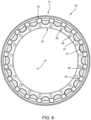
Figure 6 is a front view of the rim inFigure 4 ; and -
Figure 7 is a perspective view of an axle for a wheel hub with integrated electric traction according to the invention. - In
Figure 7 , thereference numeral 1 indicates, as a whole, an axle of a vehicle, preferably a heavy-duty vehicle, e.g. a lorry, not shown, essentially comprising acentral portion 2 and a pair ofend portions central portion 2, preferably in a rigid manner, along a longitudinal axis A of the same. - The
central portion 2 is advantageously hollow so as to define aspace 5 suitable for housing functional elements of the vehicle as described below. Preferably, theend portions continuous space 5 along the entire extension of theaxle 1 along the axis A. - The
end portions openings 6 configured to allow access to thespace 5 as described below. - Preferably, the
axle 1 comprises at least oneflange 7 arranged in the vicinity of each of theend portions central portion 2 and configured to support operating elements of the vehicle, such as, for example, mechanical brakes or sensor means. - The
axle 1 comprises a pair ofwheel hubs 10 comprising a fixedportion 8 rigidly carried by therespective end portion movable portion 9 carried in a rotationally free manner by therespective end portion - With regard to the
wheel hubs 10, for simplicity, reference will only be made to one of them, for example the left-hand one, and the following considerations apply equally to the right-hand wheel hub, of course, the structure described herein being mirrored in relation to a longitudinal plane of the vehicle. - The
fixed portion 8 is advantageously cup-shaped and comprises aradial wall 8' connected to the end of theend portion 4 and extending perpendicular to the longitudinal axis A, and acylindrical wall 8" extending from theradial wall 8' towards the vehicle, i.e., towards theintermediate portion 2 of theaxle 1. - The
radial wall 8' is advantageously connected to the end of theend portion 4 via a rigid connection, such as an interference fit connection. Preferably, theradial wall 8' is made in one piece with thecylindrical wall 8''. - The
cylindrical wall 8" is supported, on the side opposite theradial wall 8' with respect to themovable portion 9, in a rotationally free manner by support means 11 such as rolling bearings. In the embodiment described, thecylindrical wall 8'' cooperates with the support means 11 via asupport element 12 rigidly connected to thecylindrical wall 8'' and extending radially towards the aforementioned support means 11. - Preferably, the
cylindrical wall 8'' cooperates, as described above, with themovable portion 9 in a sealed manner via sealing means 13, such as rotating sealing rings, so as to delimit aspace 14 isolated from the external environment, radially delimited around the axis A by thecylindrical wall 8", and axially delimited by theradial wall 8' and themovable portion 9. - The
wheel hub 10 comprises, housed in thespace 14, anelectric machine 15 equipped with a stator 15' and arotor 15" operatively driven by the stator 15', and atransmission 16 operatively connecting therotor 15" to themovable portion 9 so as to vary the transmitted speed/torque compared to that originally supplied to therotor 15". - In particular, the stator 15' is rigidly carried by the
fixed portion 8, in particular by thecylindrical wall 8'' and thus extends along the axis A within thespace 14. - The
transmission 16 is advantageously sized so as to be radially housed within the rotor 15'' and particularly also axially included by therotor 15". - In greater detail, the
rotor 15" is connected to arotor support 17 carried in a rotationally free manner with respect to the fixedportion 8, in particular with respect to theradial wall 8', i.e., to a flanged portion extending with respect thereto. - The
rotor support 17 extends radially inside therotor 15 and essentially has the shape of an annular disc housed around theend portion 4. Therotor support 17 is operatively connected via thetransmission 16 to themovable portion 9. - In detail, the
transmission 16 comprises a gear train, advantageously a differential gear train. - In greater detail, the
transmission 16 comprises a firstbevel gear wheel 21 rigidly connected to therotor support 17 and rotationally free in relation to theend 4, a secondbevel gear wheel 22 rigidly carried by theend 4, and a plurality ofsatellites 23 operatively cooperating with the first and secondbevel gear wheels - The
satellites 23 can be of various numbers and are supported in a rotationally free manner in relation to the plane of axis B perpendicular to the axis A viarespective pins 24. By way of example only, there are foursatellites 23 supported byrespective pins 24 arranged crosswise in relation to one another. - Each
pin 23 is rigidly carried by acarrier 25 rigidly connected to themovable portion 9. - The
transmission 16 is provided with sealing means 13, e.g., carried between thefirst gear wheel 21 and theend 4, further configured to isolate thespace 14. - In this way, the
space 14 can be supplied with lubricating fluid, such as oil, via aport 26, for example carried by the rotatingportion 9, in order to lubricate thetransmission 16. - The
movable portion 9, as mentioned above, is supported in a rotationally free manner by support means 12, such as rolling bearings, at theend 4. The embodiment described comprises a main movable portion 9' and an auxiliarymovable portion 9" rigidly connected to each other. - Advantageously, the main movable portion 9' essentially comprises a
main portion 9a, preferably an annular disc, cooperating with the aforementioned support means 12, and a first flangedportion 9b extending axially cantilevered along the axis A in relation to themain portion 9a and rigidly connected to thecarrier 25. Accordingly, the first flangedportion 9b extends radially inside therotor 15". - Advantageously, the main movable portion 9' comprises a second flanged
portion 9c radially extending from themain portion 9a and rigidly connected to arim 30 as described in detail below. - The auxiliary
movable portion 9" extends from the side opposite thefixed portion 8 and is configured to provide support for operating elements of the vehicle, such as sensors or other elements that need to be integral with themovable portion 9. - The
wheel hub 10 also comprises aconditioning system 40 configured to cool thefixed portion 8, i.e., the stator 15' connected to it. Advantageously, theconditioning system 40 is a fluid conditioning system. - As shown in
Figures 1 to 3 , theconditioning system 40 comprises a plurality ofducts 41 in which a conditioning fluid flows and which are adjacent to the stator 15'. Advantageously, theseducts 41 are integrated into thefixed portion 8, i.e. thecylindrical portion 8''. - Advantageously, these
ducts 41 are made asgrooves 42 defined radially recessed with respect to the surface opposite thespace 14 of thecylindrical portion 8" and isolated from the external environment by acover 43 rigidly carried on the cylindrical portion in a sealed manner, in order to delimit theseducts 41. - The
ducts 41 are fluidically connected to adelivery pipe 44 and areturn pipe 45 configured to supply the low temperature conditioning fluid and collect the high temperature conditioning fluid once it has flowed through theducts 41 to cool the fixedportion 8. - As better shown in
Figure 3 , theducts 41 are substantially circumferential around the axis A and advantageously of square cross-section. In particular, they have the same size and are equally spaced along the axis A. - Advantageously, the
ducts 41 are fluidically connected to thedelivery pipe 44 and thereturn pipe 45 viarespective manifolds 46, which are advantageously integrated into thefixed portion 8, i.e. thecylindrical portion 8''. - Advantageously, these
manifolds 46 are made as asingle groove 47 defined radially recessed with respect to the surface opposite thespace 14 of thecylindrical portion 8'' and isolated from the external environment by thesame cover 43 delimiting theducts 41. In detail, thegroove 47 extends along the axis A throughout the length of thecylindrical portion 8" in which theducts 41 are made so that it can fluidically communicate with each of the latter. - The delivery and return
pipes - Advantageously, the
delivery pipes space 5 and extend between respectivefluidic connectors 48, as shown inFigure 7 , which are configured to allow connection to additional pipes (not shown) connecting to the aforementioned heat exchanger of the vehicle. Preferably, thefluidic connectors 48 are made in thecentral portion 2 of theaxle 1. - On the opposite side, the
delivery pipes space 5 through theopening 6 and are directed to connect to themanifolds 46 within aspace 51 delimited between the fixedportion 8 and ahead element 52 connected to it. - Therefore, this
space 51 is radially delimited by the fixedportion 8, in particular by a flange extending between thecylindrical portion 8'' and theradial portion 8' on the side opposite thecylindrical portion 8'', and axially delimited by thehead element 52 and theradial portion 8'. - In particular, the
head element 52, in the embodiment shown, is rigidly connected to thecover 43. Clearly, in an alternative embodiment, it could be made in one piece with it. - The
wheel hub 10 further comprisescables 53 for the electrical connection of theelectric machine 15 to electric power storage means (not shown) such as the battery, of the vehicle. - Advantageously, the
cables 53 are housed within thespace 5 and extend between respectiveelectrical connectors 54, as shown inFigure 7 , which are configured to allow connection to additional cables (not shown) connecting to the aforementioned electric power storage means. Preferably, theelectrical connectors 54 are made in thecentral portion 2 of theaxle 1. - On the opposite side, the
cables 43 exit thespace 5 through theopening 6 into theaforementioned space 51 and pass through a dedicated sealed opening into thespace 14, towards the stator 15' of theelectric machine 15. - Going back to the
rim 30, it comprises arim 31 configured to cooperate with a vehicle tire, and adisc 32, which are rigidly connected to each other, for example by welding, as known per se. - In particular, the
disc 32 is shaped so as to allow thewheel hub 10 to be housed inside it. - In greater detail, the
disc 32 comprises acoupling portion 33, advantageously comprising an annular disc, and astructural portion 34 configured to provide adequate stiffness to therim 30 and allow connection to therim 31. - In detail, the
structural portion 34 is rigidly connected at a connecting portion thereof 34', opposite the one connected at thecoupling portion 33, to therim 31, i.e. to an inner radial surface thereof 31'. - Advantageously, the
structural portion 34 is inclined along the axis A and is shaped like a substantially frusto-conical annular disc so as to have a larger opening diameter at therim 31 and asmaller opening diameter 35 at thecoupling portion 33. - In detail, the
structural portion 34 is inclined between the larger opening diameter and thesmaller opening diameter 35 by a value between 15° and 25°, in particular 20°. The inclination provided allows asmaller opening diameter 35 of at least 400 mm to be obtained. - Preferably, the
structural portion 34 has a corrugated profile, preferably made circumferentially to the axis A. In greater detail, this corrugated profile comprises a plurality ofgrooves 36 made parallel to the axis A and alternating with each other by a plurality ofprojections 37. - Preferably, the
grooves 36 have a substantially curved cross-section, advantageously concave towards therim 31. In greater detail, theprojections 37 define a substantially flat surface with a constant cross-section between the connecting portion 34' and thecoupling portion 33. - Advantageously, both the
grooves 36 and theprojections 37 each have the same shape as each other. In this way, preferably, they can be angularly equidistant around the axis A. - The
coupling portion 33 is substantially flat and defines a plurality ofopenings 38, which are advantageously circumferentially equidistant with respect to the axis A to enable fastening, for example as illustrated via threaded means, to theflange 9c of themovable portion 9. - The operation of the embodiment of the wheel hub, axle and vehicle according to the invention described above is as follows, referring to the torque lines in
Figure 2 . - In a first, traction operating condition, the stator 15', powered by the
electric cables 53 uses the electric power supplied to it to cooperate electromagnetically with the rotor 15'', causing it to rotate; the latter rotates integral with therotor holder 17, which in turn drags thegear wheel 21. The latter rotates thesatellites 23, which mesh between thegear wheels carrier 25 to rotate by means of thepins 24. In this way, thecarrier 25 drags themovable portion 9 to which it is connected which is directly connected to therim 30 which is then rotated, thereby moving the vehicle. - In a second, regenerative operating condition, the
rim 30 rotates themovable portion 9, which rotates thecarrier 25 which drags, by means of thepins 24, thesatellites 23 which, by meshing between thewheels rotor holder 17. The latter then rotates therotor 15" which, by interacting electromagnetically with the stator 15', generates electric power that will be stored via theelectric cables 53 in the power storage means of the vehicle. - The advantages of a wheel hub, axle and vehicle according to the invention are clear from the foregoing.
- The proposed structure makes it possible to provide an axle with integrated electric traction via the wheel hub with integrated electric traction which is small in overall dimensions and low in weight.
- In particular, the housing of the electric machine in the wheel hub and of the transmission inside the free space of the rotor makes it possible to obtain a compact, lightweight traction system that is isolated from the external environment and therefore protected from wear and from the entry of dirt.
- Furthermore, the integration of the passage of the cooling and electrical power systems within the axle and the passage of the header space allows easy and optimized assembly, thereby reducing axle manufacturing times.
- Moreover, the proposed axle and wheel hub are modular and scalable according to different vehicle types and sizes.
- In addition, the use of a rim as illustrated allows the wheel hub to be easily housed internally without compromising its structural properties.
- Indeed, the particular inclination of the disc in addition to the corrugated conformation make it possible to obtain a high moment of inertia which allows it to support the loads acting thereon.
- Furthermore, the manufacturing of the illustrated rim disc is particularly cost-effective, since it does not involve the step of cutting the holes according to the prior art.
- Lastly, it is clear that modifications and variations may be made to the wheel hub, axle, and vehicle according to the present invention, without however departing from the scope of protection defined by the claims.
- Obviously, as mentioned, the
axle 1 and thewheel hub 10 can have different shapes and consist of more and different pieces. - Furthermore, the gear wheels and gearing described herein may vary, and elements not described but known to exist could be used for the assembly of a hub, an axle, and a vehicle according to the present invention.
- In addition, although a twin wheel solution is described, the wheel hub can be applied to any type of wheel, even a single wheel.
Claims (20)
- A wheel hub (10) for an axle (1) of a heavy vehicle, said wheel hub (10) comprising a fixed portion (8) configured to be rigidly carried by one end (3, 4) of said axle (1) and a movable portion (9) configured to be carried in a rotationally free manner by said end (3, 4) of said axle (1) and with respect to said fixed portion (8), said fixed portion (8) and said movable portion (9) delimiting with said end (3, 4) a space (14) isolated from the external environment, said wheel hub (10) comprising an electric machine (15) housed in said space (14) and comprising a stator (15') carried integral with said fixed portion (8) and a rotor (15"') operatively connected to said movable portion (9), said wheel hub (10) comprising a transmission (16) housed in said space (14), radially inside of said rotor (15''), and connecting said rotor (15'') to said movable portion (19) so as to vary the speed/torque between said rotor (15'') and said movable portion (9),
wherein said movable portion (9) comprises a main portion (9a) operatively connected by said transmission (16) to said rotor (15) and supported in a rotationally free manner by said end (3, 4) of said axle (2) and a connecting portion (9c) configured to allow connection radially inside of a disc of a wheel rim (30) of said vehicle. - The wheel hub according to claim 1, wherein said transmission (16) comprises a gear train.
- The wheel hub according to claim 1 or 2, wherein said transmission (16) comprises a differential gear train.
- The wheel hub according to one of claims from 1 to 3, wherein said rotor (15") is connected to said transmission through a rotor holder (17) carried rotationally free with respect to said fixed portion (8) and/or said end (3, 4) of said axle (2).
- The wheel hub according to one of the preceding claims, wherein said transmission (16) comprises a first gear wheel (21) operatively connected to said rotor (15), a second gear wheel (23) configured to be rigidly carried by said end (3, 4) of said axle (2) and a plurality of satellites (23) meshing with said first and second gear wheels (22, 23), said satellites (24) being connected via pins (24) to a carrier (25), said carrier (25) being operatively connected to said movable portion (9).
- The wheel hub according to claim 5, wherein said carrier (25) is integral with said movable portion (9).
- The wheel hub according to one of the preceding claims, comprising a conditioning system (40) for said electric machine (15).
- The wheel hub according to claim 7, wherein said conditioning system (40) is a fluid conditioning system and comprises a plurality of ducts (41) adjacent to said fixed portion (8) in the vicinity of said stator (15') configured to allow the flow of a conditioning fluid towards a heat exchanger system of said vehicle.
- The wheel hub according to claim 8, wherein said ducts (41) are integrated in said fixed portion (8).
- The wheel hub according to claim 8 or 9, wherein said ducts (41) are made by means of grooves (42) made on an external surface of said fixed portion (8) and delimited from the external environment by a cover (43) rigidly fixed to said fixed portion (8).
- The wheel hub according to one of claims 8 to 10, comprising a pair of manifolds (46) each fluidically connected to said ducts (41), said manifolds (46) being respectively connected to a delivery pipe (44) and a return pipe (45) fluidically connected to said heat exchanger system.
- The wheel hub according to one of the preceding claims, wherein said fixed portion (8) defines an opening configured to allow the stator (15') to be connected, in a sealed manner, to an electric power source of said vehicle by means of electric cables (53).
- The wheel hub according to claims 11 and 12, comprising a head element (52) rigidly connected to said fixed portion (8) so as to axially face said end portion (3, 4) of said axle (2), said head element (52) defining with said fixed portion (8) and said end portion (3, 4) a chamber (51) isolated from the external environment and from said space (14), said chamber (51) housing said delivery (44) and return (45) pipes and said electric cables (53).
- An axle (1) extending along a longitudinal axis (A) and comprising a central portion (2) and a pair of end portions (3, 4) connected to the ends of said central portion (2) along said axis (A) and respective wheel hubs (10) according to one of the preceding claims each carried by a respective end portion (3, 4).
- The axle according to claim 14, wherein said central and end portions (2, 3, 4) are hollow and define a space (5) which is contiguous through end openings (6) along said axis (A).
- The axle according to claim 15, when dependent on claim 13, wherein said space (5) is fluidically connected through said openings (6) to said space (52) and allows the passage of said delivery (44) and return (45) pipes and of said electric cables (53).
- The axle according to claim 16, wherein said central portion (2) defines fluidic connectors (48) and electrical connectors (54) configured to connect, respectively, said delivery (44) and return (45) pipes and said electric cables (53) to said heat exchanger system and said electric power source of said vehicle.
- A vehicle comprising an axle (1) according to one of claims 13 to 16.
- The vehicle according to claim 18 comprising an electric power source electrically connected by means of electric cables (53) to said stator (15') of said electric machine (15) of said wheel hub (10).
- The vehicle according to claim 18 or 19, when dependent on claims from 8 to 11, comprising a heat exchanger system fluidically connected to said conditioning system (40) of said wheel hub (10).
Applications Claiming Priority (1)
| Application Number | Priority Date | Filing Date | Title |
|---|---|---|---|
| IT102023000008436A IT202300008436A1 (en) | 2023-04-28 | 2023-04-28 | IMPROVED ELECTRIC DRIVE WHEEL HUB |
Publications (2)
| Publication Number | Publication Date |
|---|---|
| EP4454919A1 true EP4454919A1 (en) | 2024-10-30 |
| EP4454919B1 EP4454919B1 (en) | 2026-04-29 |
Family
ID=87801343
Family Applications (1)
| Application Number | Title | Priority Date | Filing Date |
|---|---|---|---|
| EP24171836.0A Active EP4454919B1 (en) | 2023-04-28 | 2024-04-23 | Improved electric traction wheel hub |
Country Status (2)
| Country | Link |
|---|---|
| EP (1) | EP4454919B1 (en) |
| IT (1) | IT202300008436A1 (en) |
Citations (9)
| Publication number | Priority date | Publication date | Assignee | Title |
|---|---|---|---|---|
| US4021690A (en) * | 1975-05-30 | 1977-05-03 | Frank Burton | Wheel borne counter rotating disc alternator |
| US6328123B1 (en) * | 1997-07-29 | 2001-12-11 | Daimlerchrysler Ag | Electrical drive for a wheel hub |
| EP2226211A1 (en) * | 2009-03-07 | 2010-09-08 | Schaeffler Technologies AG & Co. KG | Drive device for an electric vehicle |
| WO2013025096A1 (en) * | 2011-08-12 | 2013-02-21 | E-Traction Europe B.V. | In-wheel motor with brake |
| CN109229080A (en) * | 2018-10-23 | 2019-01-18 | 展欣(宁波)新能源科技有限公司 | A kind of In-wheel motor driving bridge with modified brake assembly |
| WO2019131907A1 (en) * | 2017-12-28 | 2019-07-04 | 株式会社デンソー | Wheel drive device |
| WO2020008257A1 (en) * | 2018-07-03 | 2020-01-09 | Ka Group Ag | Electrical vehicle axle |
| CN111469644A (en) * | 2019-01-24 | 2020-07-31 | 赵红伟 | Sealing heat dissipation structure and method for driving and braking wheel type engine of vehicle |
| CN114801703A (en) * | 2022-06-02 | 2022-07-29 | 大富科技(安徽)股份有限公司 | Wheel hub motor, wheel and vehicle |
-
2023
- 2023-04-28 IT IT102023000008436A patent/IT202300008436A1/en unknown
-
2024
- 2024-04-23 EP EP24171836.0A patent/EP4454919B1/en active Active
Patent Citations (9)
| Publication number | Priority date | Publication date | Assignee | Title |
|---|---|---|---|---|
| US4021690A (en) * | 1975-05-30 | 1977-05-03 | Frank Burton | Wheel borne counter rotating disc alternator |
| US6328123B1 (en) * | 1997-07-29 | 2001-12-11 | Daimlerchrysler Ag | Electrical drive for a wheel hub |
| EP2226211A1 (en) * | 2009-03-07 | 2010-09-08 | Schaeffler Technologies AG & Co. KG | Drive device for an electric vehicle |
| WO2013025096A1 (en) * | 2011-08-12 | 2013-02-21 | E-Traction Europe B.V. | In-wheel motor with brake |
| WO2019131907A1 (en) * | 2017-12-28 | 2019-07-04 | 株式会社デンソー | Wheel drive device |
| WO2020008257A1 (en) * | 2018-07-03 | 2020-01-09 | Ka Group Ag | Electrical vehicle axle |
| CN109229080A (en) * | 2018-10-23 | 2019-01-18 | 展欣(宁波)新能源科技有限公司 | A kind of In-wheel motor driving bridge with modified brake assembly |
| CN111469644A (en) * | 2019-01-24 | 2020-07-31 | 赵红伟 | Sealing heat dissipation structure and method for driving and braking wheel type engine of vehicle |
| CN114801703A (en) * | 2022-06-02 | 2022-07-29 | 大富科技(安徽)股份有限公司 | Wheel hub motor, wheel and vehicle |
Also Published As
| Publication number | Publication date |
|---|---|
| EP4454919B1 (en) | 2026-04-29 |
| IT202300008436A1 (en) | 2024-10-28 |
Similar Documents
| Publication | Publication Date | Title |
|---|---|---|
| EP3865330B1 (en) | Electric wheel assembly suitable for wheel with parallelly installed dual tire, axle, and vehicle | |
| CN108340768B (en) | Electric wheel assembly of integrated hub motor | |
| EP3778281B1 (en) | Electric wheel assembly with integrated hub motor | |
| US11498410B2 (en) | Powered axle for dual wheel work vehicle | |
| JP2017047698A (en) | Electric car | |
| JP5066925B2 (en) | Wheel drive device | |
| CN115149678B (en) | Axle assembly with electric motor module | |
| US12539755B2 (en) | Drive system for an electric vehicle | |
| US11472226B2 (en) | Lubricant supported electric motor with wheel support | |
| KR102622464B1 (en) | Power transmission device | |
| JP7070793B2 (en) | Rotating electric machine | |
| WO2022137862A1 (en) | This semiconductor device comprises: a semiconductor layer having a main surface; a first conductive-type well region formed on a surface layer portion of the main surface of the semiconductor layer; a first conductive-type first impurity region formed on a surface layer portion of the well region and having an inner wall portion; and a second conductive-type annular second impurity region formed on the surface layer portion of the well region inside the inner wall part so as to form a pn junction with the well region. | |
| GB2611465A (en) | Electric motor for an axle assembly | |
| EP4454919B1 (en) | Improved electric traction wheel hub | |
| CN212637156U (en) | Two-stage speed reduction electric wheel adopting full-disc brake | |
| US11827092B2 (en) | Vehicle with front-wheel-assist system | |
| EP4454923B1 (en) | Improved wheel for a wheel hub having integrated electric traction | |
| JP2019156392A (en) | In-wheel motor drive device | |
| EP4534313A1 (en) | Improved electric traction wheel hub | |
| EP4733107A1 (en) | Improved electric drive wheel hub | |
| EP4547508A1 (en) | Truck axle with direct drive electric motors | |
| EP4574498A1 (en) | Axle assembly having an electric motor | |
| EP4733629A1 (en) | Improved electric traction wheel hub | |
| US20240372421A1 (en) | E-machine system with stator core having cooling flow passages | |
| CN120816890A (en) | A wheel hub electric drive system with integrated heat dissipation structure |
Legal Events
| Date | Code | Title | Description |
|---|---|---|---|
| PUAI | Public reference made under article 153(3) epc to a published international application that has entered the european phase |
Free format text: ORIGINAL CODE: 0009012 |
|
| STAA | Information on the status of an ep patent application or granted ep patent |
Free format text: STATUS: THE APPLICATION HAS BEEN PUBLISHED |
|
| AK | Designated contracting states |
Kind code of ref document: A1 Designated state(s): AL AT BE BG CH CY CZ DE DK EE ES FI FR GB GR HR HU IE IS IT LI LT LU LV MC ME MK MT NL NO PL PT RO RS SE SI SK SM TR |
|
| STAA | Information on the status of an ep patent application or granted ep patent |
Free format text: STATUS: REQUEST FOR EXAMINATION WAS MADE |
|
| 17P | Request for examination filed |
Effective date: 20250415 |
|
| GRAP | Despatch of communication of intention to grant a patent |
Free format text: ORIGINAL CODE: EPIDOSNIGR1 |
|
| STAA | Information on the status of an ep patent application or granted ep patent |
Free format text: STATUS: GRANT OF PATENT IS INTENDED |
|
| GRAJ | Information related to disapproval of communication of intention to grant by the applicant or resumption of examination proceedings by the epo deleted |
Free format text: ORIGINAL CODE: EPIDOSDIGR1 |
|
| STAA | Information on the status of an ep patent application or granted ep patent |
Free format text: STATUS: REQUEST FOR EXAMINATION WAS MADE |
|
| INTG | Intention to grant announced |
Effective date: 20250919 |
|
| INTC | Intention to grant announced (deleted) | ||
| GRAP | Despatch of communication of intention to grant a patent |
Free format text: ORIGINAL CODE: EPIDOSNIGR1 |
|
| STAA | Information on the status of an ep patent application or granted ep patent |
Free format text: STATUS: GRANT OF PATENT IS INTENDED |
|
| INTG | Intention to grant announced |
Effective date: 20251124 |
|
| RIN1 | Information on inventor provided before grant (corrected) |
Inventor name: PEREIRA DE LEMOS, JOSE FRANCIVALDO Inventor name: AIMO BOOT, MARCO Inventor name: BERNARDINI, ALESSANDRO |
|
| GRAS | Grant fee paid |
Free format text: ORIGINAL CODE: EPIDOSNIGR3 |
|
| GRAA | (expected) grant |
Free format text: ORIGINAL CODE: 0009210 |
|
| STAA | Information on the status of an ep patent application or granted ep patent |
Free format text: STATUS: THE PATENT HAS BEEN GRANTED |
|
| P01 | Opt-out of the competence of the unified patent court (upc) registered |
Free format text: CASE NUMBER: UPC_APP_0009610_4454919/2026 Effective date: 20260311 |
|
| AK | Designated contracting states |
Kind code of ref document: B1 Designated state(s): AL AT BE BG CH CY CZ DE DK EE ES FI FR GB GR HR HU IE IS IT LI LT LU LV MC ME MK MT NL NO PL PT RO RS SE SI SK SM TR |
|
| REG | Reference to a national code |
Ref country code: CH Ref legal event code: F10 Free format text: ST27 STATUS EVENT CODE: U-0-0-F10-F00 (AS PROVIDED BY THE NATIONAL OFFICE) Effective date: 20260429 |