EP4454915A1 - Electric work vehicle - Google Patents
Electric work vehicle Download PDFInfo
- Publication number
- EP4454915A1 EP4454915A1 EP22910608.3A EP22910608A EP4454915A1 EP 4454915 A1 EP4454915 A1 EP 4454915A1 EP 22910608 A EP22910608 A EP 22910608A EP 4454915 A1 EP4454915 A1 EP 4454915A1
- Authority
- EP
- European Patent Office
- Prior art keywords
- motor
- battery
- motive power
- cable
- inverter
- Prior art date
- Legal status (The legal status is an assumption and is not a legal conclusion. Google has not performed a legal analysis and makes no representation as to the accuracy of the status listed.)
- Pending
Links
Images




Classifications
-
- B—PERFORMING OPERATIONS; TRANSPORTING
- B60—VEHICLES IN GENERAL
- B60K—ARRANGEMENT OR MOUNTING OF PROPULSION UNITS OR OF TRANSMISSIONS IN VEHICLES; ARRANGEMENT OR MOUNTING OF PLURAL DIVERSE PRIME-MOVERS IN VEHICLES; AUXILIARY DRIVES FOR VEHICLES; INSTRUMENTATION OR DASHBOARDS FOR VEHICLES; ARRANGEMENTS IN CONNECTION WITH COOLING, AIR INTAKE, GAS EXHAUST OR FUEL SUPPLY OF PROPULSION UNITS IN VEHICLES
- B60K1/00—Arrangement or mounting of electrical propulsion units
- B60K1/04—Arrangement or mounting of electrical propulsion units of the electric storage means for propulsion
-
- B—PERFORMING OPERATIONS; TRANSPORTING
- B60—VEHICLES IN GENERAL
- B60K—ARRANGEMENT OR MOUNTING OF PROPULSION UNITS OR OF TRANSMISSIONS IN VEHICLES; ARRANGEMENT OR MOUNTING OF PLURAL DIVERSE PRIME-MOVERS IN VEHICLES; AUXILIARY DRIVES FOR VEHICLES; INSTRUMENTATION OR DASHBOARDS FOR VEHICLES; ARRANGEMENTS IN CONNECTION WITH COOLING, AIR INTAKE, GAS EXHAUST OR FUEL SUPPLY OF PROPULSION UNITS IN VEHICLES
- B60K1/00—Arrangement or mounting of electrical propulsion units
-
- B—PERFORMING OPERATIONS; TRANSPORTING
- B60—VEHICLES IN GENERAL
- B60L—PROPULSION OF ELECTRICALLY-PROPELLED VEHICLES; SUPPLYING ELECTRIC POWER FOR AUXILIARY EQUIPMENT OF ELECTRICALLY-PROPELLED VEHICLES; ELECTRODYNAMIC BRAKE SYSTEMS FOR VEHICLES IN GENERAL; MAGNETIC SUSPENSION OR LEVITATION FOR VEHICLES; MONITORING OPERATING VARIABLES OF ELECTRICALLY-PROPELLED VEHICLES; ELECTRIC SAFETY DEVICES FOR ELECTRICALLY-PROPELLED VEHICLES
- B60L50/00—Electric propulsion with power supplied within the vehicle
- B60L50/50—Electric propulsion with power supplied within the vehicle using propulsion power supplied by batteries or fuel cells
- B60L50/51—Electric propulsion with power supplied within the vehicle using propulsion power supplied by batteries or fuel cells characterised by AC-motors
-
- B—PERFORMING OPERATIONS; TRANSPORTING
- B60—VEHICLES IN GENERAL
- B60L—PROPULSION OF ELECTRICALLY-PROPELLED VEHICLES; SUPPLYING ELECTRIC POWER FOR AUXILIARY EQUIPMENT OF ELECTRICALLY-PROPELLED VEHICLES; ELECTRODYNAMIC BRAKE SYSTEMS FOR VEHICLES IN GENERAL; MAGNETIC SUSPENSION OR LEVITATION FOR VEHICLES; MONITORING OPERATING VARIABLES OF ELECTRICALLY-PROPELLED VEHICLES; ELECTRIC SAFETY DEVICES FOR ELECTRICALLY-PROPELLED VEHICLES
- B60L50/00—Electric propulsion with power supplied within the vehicle
- B60L50/50—Electric propulsion with power supplied within the vehicle using propulsion power supplied by batteries or fuel cells
- B60L50/60—Electric propulsion with power supplied within the vehicle using propulsion power supplied by batteries or fuel cells using power supplied by batteries
-
- B—PERFORMING OPERATIONS; TRANSPORTING
- B60—VEHICLES IN GENERAL
- B60L—PROPULSION OF ELECTRICALLY-PROPELLED VEHICLES; SUPPLYING ELECTRIC POWER FOR AUXILIARY EQUIPMENT OF ELECTRICALLY-PROPELLED VEHICLES; ELECTRODYNAMIC BRAKE SYSTEMS FOR VEHICLES IN GENERAL; MAGNETIC SUSPENSION OR LEVITATION FOR VEHICLES; MONITORING OPERATING VARIABLES OF ELECTRICALLY-PROPELLED VEHICLES; ELECTRIC SAFETY DEVICES FOR ELECTRICALLY-PROPELLED VEHICLES
- B60L50/00—Electric propulsion with power supplied within the vehicle
- B60L50/50—Electric propulsion with power supplied within the vehicle using propulsion power supplied by batteries or fuel cells
- B60L50/60—Electric propulsion with power supplied within the vehicle using propulsion power supplied by batteries or fuel cells using power supplied by batteries
- B60L50/66—Arrangements of batteries
-
- B—PERFORMING OPERATIONS; TRANSPORTING
- B62—LAND VEHICLES FOR TRAVELLING OTHERWISE THAN ON RAILS
- B62D—MOTOR VEHICLES; TRAILERS
- B62D49/00—Tractors
-
- B—PERFORMING OPERATIONS; TRANSPORTING
- B60—VEHICLES IN GENERAL
- B60K—ARRANGEMENT OR MOUNTING OF PROPULSION UNITS OR OF TRANSMISSIONS IN VEHICLES; ARRANGEMENT OR MOUNTING OF PLURAL DIVERSE PRIME-MOVERS IN VEHICLES; AUXILIARY DRIVES FOR VEHICLES; INSTRUMENTATION OR DASHBOARDS FOR VEHICLES; ARRANGEMENTS IN CONNECTION WITH COOLING, AIR INTAKE, GAS EXHAUST OR FUEL SUPPLY OF PROPULSION UNITS IN VEHICLES
- B60K1/00—Arrangement or mounting of electrical propulsion units
- B60K1/04—Arrangement or mounting of electrical propulsion units of the electric storage means for propulsion
- B60K2001/0405—Arrangement or mounting of electrical propulsion units of the electric storage means for propulsion characterised by their position
- B60K2001/0411—Arrangement in the front part of the vehicle
-
- B—PERFORMING OPERATIONS; TRANSPORTING
- B60—VEHICLES IN GENERAL
- B60L—PROPULSION OF ELECTRICALLY-PROPELLED VEHICLES; SUPPLYING ELECTRIC POWER FOR AUXILIARY EQUIPMENT OF ELECTRICALLY-PROPELLED VEHICLES; ELECTRODYNAMIC BRAKE SYSTEMS FOR VEHICLES IN GENERAL; MAGNETIC SUSPENSION OR LEVITATION FOR VEHICLES; MONITORING OPERATING VARIABLES OF ELECTRICALLY-PROPELLED VEHICLES; ELECTRIC SAFETY DEVICES FOR ELECTRICALLY-PROPELLED VEHICLES
- B60L2200/00—Type of vehicles
- B60L2200/40—Working vehicles
-
- B—PERFORMING OPERATIONS; TRANSPORTING
- B60—VEHICLES IN GENERAL
- B60L—PROPULSION OF ELECTRICALLY-PROPELLED VEHICLES; SUPPLYING ELECTRIC POWER FOR AUXILIARY EQUIPMENT OF ELECTRICALLY-PROPELLED VEHICLES; ELECTRODYNAMIC BRAKE SYSTEMS FOR VEHICLES IN GENERAL; MAGNETIC SUSPENSION OR LEVITATION FOR VEHICLES; MONITORING OPERATING VARIABLES OF ELECTRICALLY-PROPELLED VEHICLES; ELECTRIC SAFETY DEVICES FOR ELECTRICALLY-PROPELLED VEHICLES
- B60L2210/00—Converter types
- B60L2210/40—DC to AC converters
Definitions
- the present invention relates to an electric work vehicle.
- Patent Document 1 there is a work vehicle (riding-type mower) in which an engine and an engine hood for housing the engine are provided at the front part of a traveling body, the work vehicle being configured to travel due to the output of the engine.
- a work vehicle riding-type mower
- an engine and an engine hood for housing the engine are provided at the front part of a traveling body, the work vehicle being configured to travel due to the output of the engine.
- Patent Document 1 Japanese Patent Application Publication No. 2019-80514 ( JP 2019-80514A )
- the present invention provides an electric work vehicle including a battery on a front part of a traveling body in such a manner as to be able to effectively use the battery.
- An electric work vehicle includes: a travel motor provided in a traveling body of the electric work vehicle; a battery provided at a front part of the traveling body and configured to supply electric power to the motor; a cable configured to extract electric power from the battery; and a cover member covering the battery and the cable, in which the cable extends from a rear part of the battery.
- the battery is located on a body frontward side relative to the cable at a portion covered by the cover member located at the front part of the traveling body, and therefore, compared to the case where the cable extends from the front part of the battery, the load of the battery is applied to the front part of the traveling body and balance is easier to achieve when a large load is applied rearward, such as in towing work.
- the load applied by the battery can be used as part of the balance weight.
- the motor is provided below the battery.
- the load of the motor is applied to the traveling body at a position lower than the battery, and therefore it is possible to avoid a case in which the position of the center of gravity of the traveling body becomes higher than the motor.
- inverter device connected to the cable and the motor, in which the inverter device is provided below the battery while being arranged side by side with the motor in a body front-rear-direction.
- the inverter device and the motor can be connected to each other below the battery, and therefore the inverter device and the motor are easily connected to each other.
- the inverter device and the motor can be protected by the cover such that the inverter device and the motor are not hit by dirt, stones, and the like that are thrown up from below the traveling body.
- a front motive power extraction shaft provided at a front part of the traveling body and configured to extract motive power from the motor.
- the motive power from the motor can be extracted by the front motive power extraction shaft, and therefore when a work device such as a front mower or snow removal device is connected to the front part of the traveling body, the motive power from the motor is easily taken into the connected work device.
- the tractor includes left and right front wheels 10, left and right rear wheels 11, and a cover member 12.
- the tractor also includes a body frame 2 and a driving section 3.
- the body frame 2 is supported by the left and right front wheels 10 and the left and right rear wheels 11.
- the cover member 12 is disposed at a front part of the body of the tractor.
- the driving section 3 is behind the cover member 12. In other words, the cover member 12 is in front of the driving section 3.
- the driving section 3 includes a protective frame 30, a driver's seat 31, and a steering wheel 32.
- An operator can sit on the driver's seat 31. Accordingly, the operator can get in the driving section 3.
- the operator steers the left and right front wheels 10 by operating the steering wheel 32.
- the operator can perform various driving operations in the driving section 3.
- the tractor includes a travel battery 4.
- the cover member 12 is configured to be pivotable about an opening/closing axis Q extending in the left-right direction of the body. Accordingly, the cover member 12 is configured to be openable and closable. When the cover member 12 is closed, the travel battery 4 is covered by the cover member 12.
- the tractor includes an inverter 14 and a motor M.
- the travel battery 4 supplies power to the inverter 14.
- the inverter 14 converts DC power supplied from the travel battery 4 to AC power, and supplies the AC power to the motor M.
- the motor M is driven by the AC power supplied from the inverter 14.
- the tractor includes a hydraulic continuously variable transmission 15 and a transmission 16.
- the hydraulic continuously variable transmission 15 includes a hydraulic pump 15a and a hydraulic motor 15b.
- the hydraulic pump 15a is driven by rotational motive power transmitted from the motor M. As a result of the hydraulic pump 15a being driven, rotational motive power is output from the hydraulic motor 15b.
- the hydraulic continuously variable transmission 15 is configured to change the speed of rotational motive power between the hydraulic pump 15a and the hydraulic motor 15b. Also, the hydraulic continuously variable transmission 15 is configured to be capable of changing the transmission ratio in a stepless manner.
- the rotational motive power output from the hydraulic motor 15b is transmitted to the transmission 16.
- the speed of the rotational motive power transmitted to the transmission 16 is changed by a gear transmission mechanism included in the transmission 16, and the rotational motive power is distributed to the left and right front wheels 10 and the left and right rear wheels 11.
- the left and right front wheels 10 and the left and right rear wheels 11 are driven.
- the tractor also includes a middle PTO shaft 17 and a rear PTO shaft 18.
- Rotational motive power output from the motor M is distributed to the hydraulic pump 15a, the middle PTO shaft 17, and the rear PTO shaft 18.
- the middle PTO shaft 17 and the rear PTO shaft 18 are rotated by the distributed rotational motive power.
- a work device is connected to the middle PTO shaft 17 or the rear PTO shaft 18, the work device is driven by rotational motive power transmitted by the middle PTO shaft 17 or the rear PTO shaft 18.
- a grass cutting device 19 is connected to the middle PTO shaft 17 as shown in FIG. 2 .
- the grass cutting device 19 is driven by rotational motive power transmitted by the middle PTO shaft 17.
- An electric grass cutter (an example of an “electric work vehicle”) includes a tractor and a grass cutting device 19, as shown in FIG. 1 .
- the tractor has a traveling body including the body frame 2, the left and right front wheels 10, and the left and right rear wheels 11.
- the direction of arrow F shown in FIGS. 4 and 5 indicates the frontward direction of the traveling body
- the direction of arrow B indicates the rearward direction of the traveling body
- the direction of arrow U indicates the upward direction of the traveling body
- the direction of arrow D indicates the downward direction of the traveling body
- the direction of arrow R shown in FIG. 5 indicates the rightward direction of the traveling body
- the direction of arrow L indicates the leftward direction of the traveling body.
- the body frame 2 includes a pair of left and right main frames 2a and the like.
- the pair of left and right main frames 2a are provided in such a manner as to extend along the front-rear direction of the traveling body.
- the grass cutting device 19 is supported at a portion of the body frame 2 between the front wheels 10 and the rear wheels 11 in such a manner as to be movable up and down.
- an engine portion 20 including the motor M and the like is formed at the front part of the traveling body.
- a driving section 3 is formed at the rear part of the traveling body.
- the driving section 3 includes a panel cover 36 having an instrument panel (not shown).
- the engine portion 20 includes a battery room 21 formed by the cover member 12. As described above, the battery room 21 is provided with the motor M, which is a motive power source for the front wheels 10 and the rear wheels 11, the travel battery 4, and the inverter 14. A radiator 22 that cools the inverter 14 is in front of the inverter 14. A rotary fan 23 that introduces cooling air into the radiator 22 is behind the radiator 22. An oil cooler 33 is behind the rotary fan 23.
- the travel battery 4 is placed on and fixed to a base frame 24 supported by the body frame 2.
- the base frame 24 is supported on the body frame 2 due to leg members 24a provided at a plurality of locations on the base frame 24 being supported by support portions 25 provided on the pair of left and right main frames 2a.
- the motor M and the inverter 14 are provided below the travel battery 4 in such a manner as to be arranged side by side in the body front-rear direction.
- the motor M is behind the inverter 14 and the motor M is below the lower part of the travel battery 4, but there is no limitation to this, and the motor M may also be in front of the inverter 14.
- the motor M is supported by the support members 34 connected to a pair of left and right main frames 2a.
- the inverter 14 is placed on and fixed to the support portions 25 provided on the pair of left and right main frames 2a.
- the inverter 14 is located between the left and right leg members 24a.
- the travel battery 4 and the inverter 14 are connected to each other by a first cable 26 extending from the rear part of the travel battery 4.
- the first cable 26 is wired so as to extend downward behind the travel battery 4 from an output port 4a included in a rear part of the travel battery 4, and extend in the body frontward direction in the space between the travel battery 4 and the inverter 14 from behind and below the travel battery 4, and such that the extension end portion thereof connects to the input port 14a provided in the front part of the inverter 14.
- the output port 14b provided in the lower part of the inverter 14 and the input port M1 provided in the front part of the motor M are connected to each other by the second cable 27.
- the DC power stored in the travel battery 4 is extracted by the first cable 26, supplied to the inverter 14, and converted into AC power, and the AC power resulting from conversion is supplied from the inverter 14 to the motor M by the second cable 27.
- the cable 29 shown in FIG. 5 is a charging cable that extends from the charging port 4b included at the rear part of the travel battery 4.
- the travel battery 4 includes a battery case portion supported by the base frame 24 and a battery body accommodated in the battery case portion.
- the output port 4a and the charging port 4b are provided in the rear wall of the battery case.
- the cover member 12 covers the motor M, the travel battery 4, the inverter 14, the first cable 26, and the radiator 22.
- the cover member 12 includes a top plate 12a that covers the travel battery 4, the first cable 26, and the radiator 22 from above, left and right side plates 12b that cover the motor M, the travel battery 4, the inverter 14, the first cable 26, and the radiator 22 from both sides, and a front plate 12c that covers the travel battery 4, the first cable 26, the inverter 14, and the radiator 22 from the front.
- the left and right side plates 12b each include an upper side plate 12u extending downward from the lateral end of the top plate 12a, and a lower side plate 12d formed separately from the upper side plate 12u, but the upper side plate 12u and the lower side plate 12d may also be formed in one piece.
- the front plate 12c is formed integrally with the top plate 12a, but the front plate 12c and the top plate 12a may also be formed separately from each other.
- the traveling body includes a cover 35 that covers the motor M, the inverter 14, and the second cable 27 from below.
- the cover 35 is supported by a pair of left and right main frames 2a.
- the cover 35 prevents dirt, stones, and the like thrown up by the front wheels 10 and the like from hitting the motor M, the inverter 14, and the second cable 27.
- This invention is applicable to an electric work vehicle equipped including a travel motor.
Landscapes
- Engineering & Computer Science (AREA)
- Transportation (AREA)
- Mechanical Engineering (AREA)
- Life Sciences & Earth Sciences (AREA)
- Sustainable Development (AREA)
- Sustainable Energy (AREA)
- Power Engineering (AREA)
- Chemical & Material Sciences (AREA)
- Combustion & Propulsion (AREA)
- Arrangement Or Mounting Of Propulsion Units For Vehicles (AREA)
- Harvester Elements (AREA)
Abstract
Description
- The present invention relates to an electric work vehicle.
- For example, as shown in
Patent Document 1, there is a work vehicle (riding-type mower) in which an engine and an engine hood for housing the engine are provided at the front part of a traveling body, the work vehicle being configured to travel due to the output of the engine. - Patent Document 1:
Japanese Patent Application Publication No. 2019-80514 JP 2019-80514A - In order to obtain an electric work vehicle including a travel motor instead of an engine, it is necessary to include a battery that supplies power to the motor, and the weight of the battery is applied to the traveling body.
- The present invention provides an electric work vehicle including a battery on a front part of a traveling body in such a manner as to be able to effectively use the battery.
- An electric work vehicle according to the present invention includes: a travel motor provided in a traveling body of the electric work vehicle; a battery provided at a front part of the traveling body and configured to supply electric power to the motor; a cable configured to extract electric power from the battery; and a cover member covering the battery and the cable, in which the cable extends from a rear part of the battery.
- According to this configuration, the battery is located on a body frontward side relative to the cable at a portion covered by the cover member located at the front part of the traveling body, and therefore, compared to the case where the cable extends from the front part of the battery, the load of the battery is applied to the front part of the traveling body and balance is easier to achieve when a large load is applied rearward, such as in towing work. As a result, in response to the load on the front part of the traveling body increasing due to attaching a balance weight to the front part of the traveling body, it is possible to achieve a reduction of the attached balance weight due to the load applied by the battery. That is, the load applied by the battery can be used as part of the balance weight.
- In the present invention,
it is preferable that the motor is provided below the battery. - According to this configuration, the load of the motor is applied to the traveling body at a position lower than the battery, and therefore it is possible to avoid a case in which the position of the center of gravity of the traveling body becomes higher than the motor.
- In the present invention,
it is preferable to include an inverter device connected to the cable and the motor, in which the inverter device is provided below the battery while being arranged side by side with the motor in a body front-rear-direction. - According to this configuration, the inverter device and the motor can be connected to each other below the battery, and therefore the inverter device and the motor are easily connected to each other.
- In the present invention,
it is preferable to include a cover covering the motor and the inverter device from below. - According to this configuration, the inverter device and the motor can be protected by the cover such that the inverter device and the motor are not hit by dirt, stones, and the like that are thrown up from below the traveling body.
- In the present invention,
it is preferable to include a front motive power extraction shaft provided at a front part of the traveling body and configured to extract motive power from the motor. - According to this configuration, the motive power from the motor can be extracted by the front motive power extraction shaft, and therefore when a work device such as a front mower or snow removal device is connected to the front part of the traveling body, the motive power from the motor is easily taken into the connected work device.
-
-
FIG. 1 is a left side view of a tractor. -
FIG. 2 is a left side view showing an arrangement of an inverter and the like. -
FIG. 3 is a diagram showing a flow of motive power transmission. -
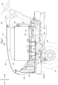
FIG. 4 is a side view showing an engine portion. -
FIG. 5 is a front view showing a wiring portion of a first cable. -
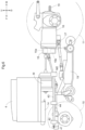
FIG. 6 is a schematic side view showing a motive power transmission device for an electric grass cutter according to a first alternative embodiment. -
FIG. 7 is a schematic side view showing a motive power transmission device for an electric grass cutter according to a second alternative embodiment. - An embodiment of the present invention will be described based on the drawings. In the following description, the direction of arrow F in the drawings is "front", the direction of arrow B is "rear", the direction of arrow L is "left", and the direction of arrow R is "right", unless otherwise stated. Also, the direction of arrow U in the drawings is "up", and the direction of arrow D is "down".
- The following describes a tractor according to the present embodiment. As shown in
FIG. 1 , the tractor includes left and rightfront wheels 10, left and rightrear wheels 11, and acover member 12. - The tractor also includes a
body frame 2 and adriving section 3. Thebody frame 2 is supported by the left and rightfront wheels 10 and the left and rightrear wheels 11. - The
cover member 12 is disposed at a front part of the body of the tractor. Thedriving section 3 is behind thecover member 12. In other words, thecover member 12 is in front of thedriving section 3. - The
driving section 3 includes aprotective frame 30, a driver'sseat 31, and asteering wheel 32. An operator can sit on the driver'sseat 31. Accordingly, the operator can get in thedriving section 3. The operator steers the left and rightfront wheels 10 by operating thesteering wheel 32. The operator can perform various driving operations in thedriving section 3. - The tractor includes a
travel battery 4. Thecover member 12 is configured to be pivotable about an opening/closing axis Q extending in the left-right direction of the body. Accordingly, thecover member 12 is configured to be openable and closable. When thecover member 12 is closed, thetravel battery 4 is covered by thecover member 12. - As shown in
FIG. 2 , the tractor includes aninverter 14 and a motor M. Thetravel battery 4 supplies power to theinverter 14. Theinverter 14 converts DC power supplied from thetravel battery 4 to AC power, and supplies the AC power to the motor M. The motor M is driven by the AC power supplied from theinverter 14. - As shown in
FIGS. 2 and3 , the tractor includes a hydraulic continuouslyvariable transmission 15 and atransmission 16. As shown inFIG. 3 , the hydraulic continuouslyvariable transmission 15 includes ahydraulic pump 15a and ahydraulic motor 15b. - The
hydraulic pump 15a is driven by rotational motive power transmitted from the motor M. As a result of thehydraulic pump 15a being driven, rotational motive power is output from thehydraulic motor 15b. The hydraulic continuouslyvariable transmission 15 is configured to change the speed of rotational motive power between thehydraulic pump 15a and thehydraulic motor 15b. Also, the hydraulic continuouslyvariable transmission 15 is configured to be capable of changing the transmission ratio in a stepless manner. - The rotational motive power output from the
hydraulic motor 15b is transmitted to thetransmission 16. The speed of the rotational motive power transmitted to thetransmission 16 is changed by a gear transmission mechanism included in thetransmission 16, and the rotational motive power is distributed to the left and rightfront wheels 10 and the left and rightrear wheels 11. Thus, the left and rightfront wheels 10 and the left and rightrear wheels 11 are driven. - As shown in
FIGS. 2 and3 , the tractor also includes amiddle PTO shaft 17 and arear PTO shaft 18. Rotational motive power output from the motor M is distributed to thehydraulic pump 15a, themiddle PTO shaft 17, and therear PTO shaft 18. Themiddle PTO shaft 17 and therear PTO shaft 18 are rotated by the distributed rotational motive power. - If a work device is connected to the
middle PTO shaft 17 or therear PTO shaft 18, the work device is driven by rotational motive power transmitted by themiddle PTO shaft 17 or therear PTO shaft 18. For example, in the present embodiment, agrass cutting device 19 is connected to themiddle PTO shaft 17 as shown inFIG. 2 . Thegrass cutting device 19 is driven by rotational motive power transmitted by themiddle PTO shaft 17. - An electric grass cutter (an example of an "electric work vehicle") includes a tractor and a
grass cutting device 19, as shown inFIG. 1 . As shown inFIG. 1 , the tractor has a traveling body including thebody frame 2, the left and rightfront wheels 10, and the left and rightrear wheels 11. - The direction of arrow F shown in
FIGS. 4 and5 indicates the frontward direction of the traveling body, the direction of arrow B indicates the rearward direction of the traveling body, the direction of arrow U indicates the upward direction of the traveling body, the direction of arrow D indicates the downward direction of the traveling body, the direction of arrow R shown inFIG. 5 indicates the rightward direction of the traveling body, and the direction of arrow L indicates the leftward direction of the traveling body. - As shown in
FIGS. 4 and5 , thebody frame 2 includes a pair of left and rightmain frames 2a and the like. The pair of left and rightmain frames 2a are provided in such a manner as to extend along the front-rear direction of the traveling body. Thegrass cutting device 19 is supported at a portion of thebody frame 2 between thefront wheels 10 and therear wheels 11 in such a manner as to be movable up and down. As shown inFIGS. 1 and4 , anengine portion 20 including the motor M and the like is formed at the front part of the traveling body. Adriving section 3 is formed at the rear part of the traveling body. Thedriving section 3 includes apanel cover 36 having an instrument panel (not shown). - As shown in
FIGS. 1 and4 , theengine portion 20 includes abattery room 21 formed by thecover member 12. As described above, thebattery room 21 is provided with the motor M, which is a motive power source for thefront wheels 10 and therear wheels 11, thetravel battery 4, and theinverter 14. Aradiator 22 that cools theinverter 14 is in front of theinverter 14. Arotary fan 23 that introduces cooling air into theradiator 22 is behind theradiator 22. Anoil cooler 33 is behind therotary fan 23. - The
travel battery 4 is placed on and fixed to abase frame 24 supported by thebody frame 2. Thebase frame 24 is supported on thebody frame 2 due toleg members 24a provided at a plurality of locations on thebase frame 24 being supported bysupport portions 25 provided on the pair of left and rightmain frames 2a. - The motor M and the
inverter 14 are provided below thetravel battery 4 in such a manner as to be arranged side by side in the body front-rear direction. In the present embodiment, the motor M is behind theinverter 14 and the motor M is below the lower part of thetravel battery 4, but there is no limitation to this, and the motor M may also be in front of theinverter 14. - The motor M is supported by the
support members 34 connected to a pair of left and rightmain frames 2a. Theinverter 14 is placed on and fixed to thesupport portions 25 provided on the pair of left and rightmain frames 2a. Theinverter 14 is located between the left andright leg members 24a. - As shown in
FIGS. 4 and5 , thetravel battery 4 and theinverter 14 are connected to each other by afirst cable 26 extending from the rear part of thetravel battery 4. Specifically, thefirst cable 26 is wired so as to extend downward behind thetravel battery 4 from anoutput port 4a included in a rear part of thetravel battery 4, and extend in the body frontward direction in the space between thetravel battery 4 and theinverter 14 from behind and below thetravel battery 4, and such that the extension end portion thereof connects to theinput port 14a provided in the front part of theinverter 14. Theoutput port 14b provided in the lower part of theinverter 14 and the input port M1 provided in the front part of the motor M are connected to each other by thesecond cable 27. - The DC power stored in the
travel battery 4 is extracted by thefirst cable 26, supplied to theinverter 14, and converted into AC power, and the AC power resulting from conversion is supplied from theinverter 14 to the motor M by thesecond cable 27. - The
cable 29 shown inFIG. 5 is a charging cable that extends from the chargingport 4b included at the rear part of thetravel battery 4. Thetravel battery 4 includes a battery case portion supported by thebase frame 24 and a battery body accommodated in the battery case portion. Theoutput port 4a and the chargingport 4b are provided in the rear wall of the battery case. - As shown in
FIGS. 4 and5 , thecover member 12 covers the motor M, thetravel battery 4, theinverter 14, thefirst cable 26, and theradiator 22. - Specifically, the
cover member 12 includes atop plate 12a that covers thetravel battery 4, thefirst cable 26, and theradiator 22 from above, left andright side plates 12b that cover the motor M, thetravel battery 4, theinverter 14, thefirst cable 26, and theradiator 22 from both sides, and afront plate 12c that covers thetravel battery 4, thefirst cable 26, theinverter 14, and theradiator 22 from the front. - In this embodiment, the left and
right side plates 12b each include anupper side plate 12u extending downward from the lateral end of thetop plate 12a, and alower side plate 12d formed separately from theupper side plate 12u, but theupper side plate 12u and thelower side plate 12d may also be formed in one piece. In this embodiment, thefront plate 12c is formed integrally with thetop plate 12a, but thefront plate 12c and thetop plate 12a may also be formed separately from each other. - As shown in
FIGS. 4 and5 , the traveling body includes acover 35 that covers the motor M, theinverter 14, and thesecond cable 27 from below. Thecover 35 is supported by a pair of left and rightmain frames 2a. Thecover 35 prevents dirt, stones, and the like thrown up by thefront wheels 10 and the like from hitting the motor M, theinverter 14, and thesecond cable 27. -
- (1)
FIG. 6 is a schematic side view showing a motive power transmission device for an electric grass cutter according to a first alternative embodiment. In the electric grass cutter of the first alternative embodiment, a first front motivepower extraction shaft 41 is provided at the front part of the traveling body. The first front motivepower extraction shaft 41 extracts motive power from the travel motor M.
Specifically, the first front motivepower extraction shaft 41 is rotatably supported by afirst support portion 42 provided at the front part of thebody frame 2. A rear part of the first front motivepower extraction shaft 41 and an output portion M2 provided in the travel motor M are connected to each other via arotation shaft 43. Therotation shaft 43 is rotatably supported by asecond support portion 44 provided in thebody frame 2 between thefirst support portion 42 and the output portion M2. The motive power output by the travel motor M from the output portion M2 is transmitted to the first front motivepower extraction shaft 41 via therotation shaft 43. - (2)
FIG. 7 is a schematic side view showing a motive power transmission device for an electric grass cutter according to a second alternative embodiment. In the electric grass cutter of the second alternative embodiment, a second front motivepower extraction shaft 45 is provided at the front part of the traveling body. The second front motivepower extraction shaft 45 extracts motive power from the travel motor M.
Specifically, the second front motivepower extraction shaft 45 is rotatably supported by afirst support portion 42 provided at the front part of thebody frame 2. A rear part of the second front motivepower extraction shaft 45 and a motivepower extraction portion 46a provided in aninput case 46 of agrass cutting device 19 are connected to each other via arotation shaft 47. Therotation shaft 47 is rotatably supported by asecond support portion 44 provided in thebody frame 2 between thefirst support portion 42 and the motivepower extraction portion 46a. Auniversal joint 48 serving as a bending portion that allows thegrass cutting device 19 to move up and down is provided at a portion of therotation shaft 47 between thesecond support portion 44 and the motivepower extraction portion 46a. The motive power output by the travel motor M is transmitted to the second front motivepower extraction shaft 45 via themiddle PTO shaft 17, theinput case 46, and therotation shaft 47. - (3) In the above-described embodiment, an example is shown in which the
grass cutting device 19 is provided, but the electric work vehicle may also include any work device such as a chemical spraying device, instead of thegrass cutting device 19. - (4) Although the above-described embodiment showed an example in which the motor M and the
inverter 14 are provided below thetravel battery 4, there is no limitation to this, and the motor M and theinverter 14 may be provided at any location, such as behind thetravel battery 4. - (5) Although the above-described embodiment showed an example in which the motor M is located on a body rearward side relative to the
inverter 14, there is no limitation to this, and the motor M may also be located on a body frontward side relative to theinverter 14. - (6) In the embodiment described above, an example was shown in which the
cover 35 was provided, but thecover 35 need not be provided. - This invention is applicable to an electric work vehicle equipped including a travel motor.
-
- 4: Travel battery (battery)
- 12: Cover member
- 14: Inverter (inverter device)
- 26: First cable (cable)
- 35: Cover
- 41: First front motive power extraction shaft (front motive power extraction shaft)
- 45: Second front motive power extraction shaft (front motive power extraction shaft)
- M: Motor
Claims (5)
- An electric work vehicle comprising:a travel motor provided in a traveling body;a battery provided at a front part of the traveling body and configured to supply electric power to the motor;a cable configured to extract electric power from the battery; anda cover member covering the battery and the cable,wherein the cable extends from a rear part of the battery.
- The electric work vehicle according to claim 1,
wherein the motor is provided below the battery. - The electric work vehicle according to claim 2, further comprisingan inverter device connected to the cable and the motor,wherein the inverter device is provided below the battery while being arranged side by side with the motor in a body front-rear-direction.
- The electric work vehicle according to claim 3, further comprising
a cover covering the motor and the inverter device from below. - The electric work vehicle according to any one of claims 1 to 4, further comprising
a front motive power extraction shaft provided at a front part of the traveling body and configured to extract motive power from the motor.
Applications Claiming Priority (2)
| Application Number | Priority Date | Filing Date | Title |
|---|---|---|---|
| JP2021211640A JP7519983B2 (en) | 2021-12-24 | 2021-12-24 | Electric work vehicle |
| PCT/JP2022/040684 WO2023119888A1 (en) | 2021-12-24 | 2022-10-31 | Electric work vehicle |
Publications (2)
| Publication Number | Publication Date |
|---|---|
| EP4454915A1 true EP4454915A1 (en) | 2024-10-30 |
| EP4454915A4 EP4454915A4 (en) | 2025-12-17 |
Family
ID=86901980
Family Applications (1)
| Application Number | Title | Priority Date | Filing Date |
|---|---|---|---|
| EP22910608.3A Pending EP4454915A4 (en) | 2021-12-24 | 2022-10-31 | ELECTRIC WORK VEHICLE |
Country Status (4)
| Country | Link |
|---|---|
| US (1) | US20240326611A1 (en) |
| EP (1) | EP4454915A4 (en) |
| JP (1) | JP7519983B2 (en) |
| WO (1) | WO2023119888A1 (en) |
Families Citing this family (1)
| Publication number | Priority date | Publication date | Assignee | Title |
|---|---|---|---|---|
| JP7498683B2 (en) * | 2021-06-29 | 2024-06-12 | 株式会社クボタ | Electric work vehicle |
Family Cites Families (7)
| Publication number | Priority date | Publication date | Assignee | Title |
|---|---|---|---|---|
| JP3713480B2 (en) | 2002-11-19 | 2005-11-09 | 日立建機株式会社 | Electric drive wheeled work vehicle |
| JP2012201187A (en) | 2011-03-24 | 2012-10-22 | Komatsu Ltd | Battery-powered wheel loader |
| JP5874549B2 (en) | 2012-06-29 | 2016-03-02 | 三菱自動車工業株式会社 | Electric vehicle |
| JP5837863B2 (en) * | 2012-08-21 | 2015-12-24 | 日立建機株式会社 | Electric construction machine |
| JP6286458B2 (en) | 2016-02-12 | 2018-02-28 | 本田技研工業株式会社 | vehicle |
| JP6925237B2 (en) | 2017-10-30 | 2021-08-25 | 株式会社クボタ | Work machine |
| JP7323349B2 (en) | 2019-06-24 | 2023-08-08 | 株式会社クボタ | electric work vehicle |
-
2021
- 2021-12-24 JP JP2021211640A patent/JP7519983B2/en active Active
-
2022
- 2022-10-31 WO PCT/JP2022/040684 patent/WO2023119888A1/en not_active Ceased
- 2022-10-31 EP EP22910608.3A patent/EP4454915A4/en active Pending
-
2024
- 2024-06-13 US US18/742,045 patent/US20240326611A1/en active Pending
Also Published As
| Publication number | Publication date |
|---|---|
| JP7519983B2 (en) | 2024-07-22 |
| WO2023119888A1 (en) | 2023-06-29 |
| US20240326611A1 (en) | 2024-10-03 |
| EP4454915A4 (en) | 2025-12-17 |
| JP2023095632A (en) | 2023-07-06 |
Similar Documents
| Publication | Publication Date | Title |
|---|---|---|
| EP4456369A1 (en) | Electric work vehicle | |
| EP3295784A1 (en) | Mid-mount riding grass mower | |
| US7159343B2 (en) | Working machine | |
| EP3741197A1 (en) | Mower unit | |
| US20240326611A1 (en) | Electric work vehicle | |
| EP4552888A1 (en) | Electric work vehicle | |
| JP6444821B2 (en) | vehicle | |
| EP3476643A1 (en) | Work machine | |
| US12409740B2 (en) | Electric work vehicle | |
| JP2025007878A (en) | Electric work vehicle | |
| EP4454914A1 (en) | Electric work vehicle | |
| JP7097806B2 (en) | Electric work vehicle | |
| EP4342707A1 (en) | Work vehicle | |
| JP7546543B2 (en) | Electric work vehicle | |
| JP7788980B2 (en) | Work vehicle | |
| JP2023112412A (en) | electric work vehicle | |
| JP7555326B2 (en) | Electric work vehicle | |
| JP2023112411A (en) | electric work vehicle | |
| EP4454913A1 (en) | Electric work vehicle | |
| JP2020104723A (en) | Electric work vehicle | |
| JP2024164319A5 (en) | ||
| JP2022101316A (en) | Work vehicle |
Legal Events
| Date | Code | Title | Description |
|---|---|---|---|
| STAA | Information on the status of an ep patent application or granted ep patent |
Free format text: STATUS: THE INTERNATIONAL PUBLICATION HAS BEEN MADE |
|
| PUAI | Public reference made under article 153(3) epc to a published international application that has entered the european phase |
Free format text: ORIGINAL CODE: 0009012 |
|
| STAA | Information on the status of an ep patent application or granted ep patent |
Free format text: STATUS: REQUEST FOR EXAMINATION WAS MADE |
|
| 17P | Request for examination filed |
Effective date: 20240613 |
|
| AK | Designated contracting states |
Kind code of ref document: A1 Designated state(s): AL AT BE BG CH CY CZ DE DK EE ES FI FR GB GR HR HU IE IS IT LI LT LU LV MC ME MK MT NL NO PL PT RO RS SE SI SK SM TR |
|
| DAV | Request for validation of the european patent (deleted) | ||
| DAX | Request for extension of the european patent (deleted) | ||
| A4 | Supplementary search report drawn up and despatched |
Effective date: 20251117 |
|
| RIC1 | Information provided on ipc code assigned before grant |
Ipc: B60K 1/04 20190101AFI20251111BHEP Ipc: B62D 49/00 20060101ALI20251111BHEP Ipc: B60K 1/00 20060101ALI20251111BHEP Ipc: B60L 50/60 20190101ALI20251111BHEP |