EP4454907A1 - Stabilizer manufacturing method, stabilizer, and tubular member for manufacturing stabilizer - Google Patents
Stabilizer manufacturing method, stabilizer, and tubular member for manufacturing stabilizer Download PDFInfo
- Publication number
- EP4454907A1 EP4454907A1 EP22911367.5A EP22911367A EP4454907A1 EP 4454907 A1 EP4454907 A1 EP 4454907A1 EP 22911367 A EP22911367 A EP 22911367A EP 4454907 A1 EP4454907 A1 EP 4454907A1
- Authority
- EP
- European Patent Office
- Prior art keywords
- reduced diameter
- central portion
- wall thickness
- stabilizer
- diameter portion
- Prior art date
- Legal status (The legal status is an assumption and is not a legal conclusion. Google has not performed a legal analysis and makes no representation as to the accuracy of the status listed.)
- Pending
Links
- 239000003381 stabilizer Substances 0.000 title claims abstract description 81
- 238000004519 manufacturing process Methods 0.000 title claims abstract description 24
- 238000003825 pressing Methods 0.000 claims abstract description 83
- 238000012545 processing Methods 0.000 claims abstract description 13
- 238000005304 joining Methods 0.000 claims description 2
- 238000012986 modification Methods 0.000 description 16
- 230000004048 modification Effects 0.000 description 16
- 239000000463 material Substances 0.000 description 8
- 239000000725 suspension Substances 0.000 description 8
- 239000013585 weight reducing agent Substances 0.000 description 5
- 239000002184 metal Substances 0.000 description 3
- 230000000149 penetrating effect Effects 0.000 description 3
- 238000005520 cutting process Methods 0.000 description 2
- 239000007787 solid Substances 0.000 description 2
- 229920000049 Carbon (fiber) Polymers 0.000 description 1
- 230000015572 biosynthetic process Effects 0.000 description 1
- 239000004917 carbon fiber Substances 0.000 description 1
- 238000013461 design Methods 0.000 description 1
- 230000000694 effects Effects 0.000 description 1
- 239000000835 fiber Substances 0.000 description 1
- 239000011796 hollow space material Substances 0.000 description 1
- 238000003780 insertion Methods 0.000 description 1
- 230000037431 insertion Effects 0.000 description 1
- 230000002452 interceptive effect Effects 0.000 description 1
- 238000005259 measurement Methods 0.000 description 1
- 238000000034 method Methods 0.000 description 1
- 230000002093 peripheral effect Effects 0.000 description 1
- 230000001629 suppression Effects 0.000 description 1
Images


Classifications
-
- B—PERFORMING OPERATIONS; TRANSPORTING
- B60—VEHICLES IN GENERAL
- B60G—VEHICLE SUSPENSION ARRANGEMENTS
- B60G21/00—Interconnection systems for two or more resiliently-suspended wheels, e.g. for stabilising a vehicle body with respect to acceleration, deceleration or centrifugal forces
- B60G21/02—Interconnection systems for two or more resiliently-suspended wheels, e.g. for stabilising a vehicle body with respect to acceleration, deceleration or centrifugal forces permanently interconnected
- B60G21/04—Interconnection systems for two or more resiliently-suspended wheels, e.g. for stabilising a vehicle body with respect to acceleration, deceleration or centrifugal forces permanently interconnected mechanically
- B60G21/05—Interconnection systems for two or more resiliently-suspended wheels, e.g. for stabilising a vehicle body with respect to acceleration, deceleration or centrifugal forces permanently interconnected mechanically between wheels on the same axle but on different sides of the vehicle, i.e. the left and right wheel suspensions being interconnected
- B60G21/055—Stabiliser bars
-
- B—PERFORMING OPERATIONS; TRANSPORTING
- B21—MECHANICAL METAL-WORKING WITHOUT ESSENTIALLY REMOVING MATERIAL; PUNCHING METAL
- B21D—WORKING OR PROCESSING OF SHEET METAL OR METAL TUBES, RODS OR PROFILES WITHOUT ESSENTIALLY REMOVING MATERIAL; PUNCHING METAL
- B21D41/00—Application of procedures in order to alter the diameter of tube ends
- B21D41/04—Reducing; Closing
-
- B—PERFORMING OPERATIONS; TRANSPORTING
- B21—MECHANICAL METAL-WORKING WITHOUT ESSENTIALLY REMOVING MATERIAL; PUNCHING METAL
- B21D—WORKING OR PROCESSING OF SHEET METAL OR METAL TUBES, RODS OR PROFILES WITHOUT ESSENTIALLY REMOVING MATERIAL; PUNCHING METAL
- B21D53/00—Making other particular articles
- B21D53/88—Making other particular articles other parts for vehicles, e.g. cowlings, mudguards
-
- B—PERFORMING OPERATIONS; TRANSPORTING
- B60—VEHICLES IN GENERAL
- B60G—VEHICLE SUSPENSION ARRANGEMENTS
- B60G21/00—Interconnection systems for two or more resiliently-suspended wheels, e.g. for stabilising a vehicle body with respect to acceleration, deceleration or centrifugal forces
- B60G21/02—Interconnection systems for two or more resiliently-suspended wheels, e.g. for stabilising a vehicle body with respect to acceleration, deceleration or centrifugal forces permanently interconnected
- B60G21/04—Interconnection systems for two or more resiliently-suspended wheels, e.g. for stabilising a vehicle body with respect to acceleration, deceleration or centrifugal forces permanently interconnected mechanically
- B60G21/05—Interconnection systems for two or more resiliently-suspended wheels, e.g. for stabilising a vehicle body with respect to acceleration, deceleration or centrifugal forces permanently interconnected mechanically between wheels on the same axle but on different sides of the vehicle, i.e. the left and right wheel suspensions being interconnected
- B60G21/055—Stabiliser bars
- B60G21/0551—Mounting means therefor
-
- B—PERFORMING OPERATIONS; TRANSPORTING
- B60—VEHICLES IN GENERAL
- B60G—VEHICLE SUSPENSION ARRANGEMENTS
- B60G2204/00—Indexing codes related to suspensions per se or to auxiliary parts
- B60G2204/10—Mounting of suspension elements
- B60G2204/12—Mounting of springs or dampers
- B60G2204/122—Mounting of torsion springs
- B60G2204/1224—End mounts of stabiliser on wheel suspension
-
- B—PERFORMING OPERATIONS; TRANSPORTING
- B60—VEHICLES IN GENERAL
- B60G—VEHICLE SUSPENSION ARRANGEMENTS
- B60G2206/00—Indexing codes related to the manufacturing of suspensions: constructional features, the materials used, procedures or tools
- B60G2206/01—Constructional features of suspension elements, e.g. arms, dampers, springs
- B60G2206/012—Hollow or tubular elements
-
- B—PERFORMING OPERATIONS; TRANSPORTING
- B60—VEHICLES IN GENERAL
- B60G—VEHICLE SUSPENSION ARRANGEMENTS
- B60G2206/00—Indexing codes related to the manufacturing of suspensions: constructional features, the materials used, procedures or tools
- B60G2206/01—Constructional features of suspension elements, e.g. arms, dampers, springs
- B60G2206/40—Constructional features of dampers and/or springs
- B60G2206/42—Springs
- B60G2206/427—Stabiliser bars or tubes
-
- B—PERFORMING OPERATIONS; TRANSPORTING
- B60—VEHICLES IN GENERAL
- B60G—VEHICLE SUSPENSION ARRANGEMENTS
- B60G2206/00—Indexing codes related to the manufacturing of suspensions: constructional features, the materials used, procedures or tools
- B60G2206/01—Constructional features of suspension elements, e.g. arms, dampers, springs
- B60G2206/80—Manufacturing procedures
- B60G2206/81—Shaping
-
- B—PERFORMING OPERATIONS; TRANSPORTING
- B60—VEHICLES IN GENERAL
- B60G—VEHICLE SUSPENSION ARRANGEMENTS
- B60G2206/00—Indexing codes related to the manufacturing of suspensions: constructional features, the materials used, procedures or tools
- B60G2206/01—Constructional features of suspension elements, e.g. arms, dampers, springs
- B60G2206/80—Manufacturing procedures
- B60G2206/81—Shaping
- B60G2206/8103—Shaping by folding or bending
Definitions
- the present invention relates to a stabilizer manufacturing method, a stabilizer, and a stabilizer manufacturing base tubular member.
- a stabilizer used in a vehicle or the like is attached to the vehicle to stabilize the posture of the vehicle.
- the stabilizer is formed by deforming a solid rod-shaped member, for example (refer to Patent Literature 1, for example).
- the stabilizer has its two ends connected to the vehicle, with each connecting portion having a planar shape.
- Each of the ends of the stabilizer is formed into a flat-plate shape by crushing a bar-shaped member, and then a hole for insertion of a bolt or the like is formed on each of the flat-plate shaped ends. At this time, both side surface portions of the flat-plate portions are cut off to adjust the width of the flat-plate portions.
- An example of implementing the weight reduction of the stabilizer is changing the material used for formation from a solid rod-like member to a hollow tubular member.
- Patent Literature 1 JP 10-193944 A
- the present invention has been made in view of the above, and aims to provide a stabilizer manufacturing method, a stabilizer, and a stabilizer manufacturing base tubular member, capable of achieving a sufficient strength in both ends of the stabilizer and weight reduction of the stabilizer.
- a stabilizer manufacturing method includes forming a first end and a second end of a stabilizer by processing a tubular member, wherein the tubular member includes: a central portion having a tubular shape; a first reduced diameter portion having a tubular shape and provided on one end side of the central portion, the first reduced diameter portion having a wall thickness equivalent to a wall thickness of the central portion and having a diameter smaller than a diameter of the central portion; a second reduced diameter portion having a tubular shape and provided on the other end side of the central portion, the second reduced diameter portion having a wall thickness equivalent to the wall thickness of the central portion and having a diameter smaller than the diameter of the central portion; a first connecting portion having a conical shape and connecting the central portion and the first reduced diameter portion to each other; and a second connecting portion having a conical shape and connecting the central portion and the second reduced diameter portion to each other, the first end and the second end constitutes both ends of the stabilizer and each has
- the first and second ends having the wall thickness equivalent to the wall thickness of the main body are formed by sandwiching and pressing each of the first and second reduced diameter portions by the pair of first pressing members and a pair of second pressing members having different facing directions from facing directions of the pair of first pressing members.
- the pair of first pressing members and the pair of second pressing members simultaneously sandwich and press the first and second reduced diameter portions.
- a stabilizer according to the present invention is formed by using a tubular member including: a central portion having a tubular shape; a first reduced diameter portion having a tubular shape and provided on one end side of the central portion, the first reduced diameter portion having a wall thickness equivalent to a wall thickness of the central portion and having a diameter smaller than a diameter of the central portion; a second reduced diameter portion having a tubular shape and provided on the other end side of the central portion, the second reduced diameter portion having a wall thickness equivalent to the wall thickness of the central portion and having a diameter smaller than the diameter of the central portion; a first connecting portion having a conical shape and connecting the central portion and the first reduced diameter portion to each other; and a second connecting portion having a conical shape and connecting the central portion and the second reduced diameter portion to each other, and includes: a main body having a tubular shape; a first end provided on one end side of the main body and having a flat plate shape, the first end formed to have an annular shape having a wall thickness equivalent to
- the first and second ends further include third and fourth planar portions formed on opposite sides to each other and having planar shapes and each positioned at joining portions of the first and second planar portions.
- a stabilizer manufacturing base tubular member includes: a central portion having a tubular shape; a first reduced diameter portion having a tubular shape and provided on one end side of the central portion, the first reduced diameter portion having a wall thickness equivalent to a wall thickness of the central portion and having a diameter smaller than a diameter of the central portion; a second reduced diameter portion having a tubular shape and provided on the other end side of the central portion, the second reduced diameter portion having a wall thickness equivalent to the wall thickness of the central portion and having a diameter smaller than the diameter of the central portion; a first connecting portion having a conical shape and connecting the central portion and the first reduced diameter portion to each other; and a second connecting portion having a conical shape and connecting the central portion and the second reduced diameter portion to each other.
- FIG. 1 is a perspective view illustrating an example of a suspension mechanism including a stabilizer according to an embodiment of the present invention.
- a suspension mechanism 100 illustrated in FIG. 1 includes a stabilizer 1, suspensions 101 and 102, and links 103 and 104.
- the suspensions 101 and 102 each include an extendable coil spring.
- the suspensions 101 and 102 are provided respectively for tires 111 and 112 (for example, front wheels) so as to absorb vibration transmitted from the tires 111 and 112 corresponding to the unevenness of a road surface.
- the suspensions 101 and 102 are connected with the stabilizer 1 via the links 103 and 104, respectively.
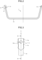
- FIG. 2 is a plan view illustrating a configuration of the stabilizer illustrated in FIG. 1 .
- FIG. 3 is a plan view of the stabilizer in a region R illustrated in FIG. 2 as viewed in the direction of arrow A.
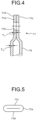
- FIG. 4 is a cross-sectional view taken along line B-B illustrated in FIG. 3 .
- FIG. 5 is a plan view illustrating an end surface of the stabilizer as viewed in the direction of arrow C illustrated in FIG. 3 .
- the stabilizer 1 is formed using a tubular member made of metal or various fibers (for example, carbon fibers).
- the stabilizer 1 includes: a main body 10; a first end 11 continuous with one end of the main body 10; and a second end 12 continuous with the other end of the main body 10.
- the main body 10 has its central portion extending in a straight line shape, and has its both ends formed to be bent.
- the first end 11 has a flat portion 11a having a flat shape.
- the flat portion 11a has a hole 11b penetrating in the thickness direction (refer to FIGS. 3 and 4 ).
- a wall thickness T 10 of the main body 10 and a wall thickness T 11 of the first end 11 are equivalent to or substantially equal to each other.
- the term "substantially equal” as used herein represents equality including a difference in the degree of manufacturing error.
- the first end 11 has a closed annular shape (shape in which inner peripheral surfaces of the portions are in contact with each other) in plan view in the direction of arrow C (refer to FIG. 5 ).
- the shape of the portion, in the plan view is not limited to the closed annular shape illustrated in FIG. 5 , and may be an annular shape having a hollow space. At this time, a closed annular shape is preferable from the viewpoint of achieving a sufficient strength of the first end 11.
- the first end 11 includes planar portions 11c and 11d.
- the planar portion 11c comes into contact with a fastening member such as a bolt head, a washer, or a nut, for example.
- the surface of the stabilizer 1 with which the fastening member comes into contact is preferably a planar surface.
- the second end 12 has a shape similar to the shape of the first end 11.
- the second end 12 has a flat portion having a flat shape, and has a hole penetrating in the thickness direction.
- the second end 12 has a wall thickness equivalent to or substantially equal to a wall thickness of the main body 10.
- the stabilizer 1 is fabricated by processing a base material.
- a tubular base material is bent, and then, both ends of the material are processed into flat plate shapes. Thereafter, a through hole is formed at each end.
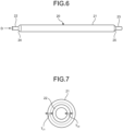
- FIG. 6 is a perspective view illustrating a configuration of a tubular member for fabricating the stabilizer according to an embodiment of the present invention.
- FIG. 7 is a plan view illustrating an end surface of the tubular member as viewed in the direction of arrow D illustrated in FIG. 6 .
- a tubular member 20 to be a base material of the stabilizer 1 includes: a central portion 21 having a tubular shape; a first reduced diameter portion 22 provided on one end side of the central portion 21 and having a tubular shape with a diameter smaller than the diameter of the central portion 21; a second reduced diameter portion 23 provided on the other end side of the central portion 21 and having a tubular shape with a diameter smaller than the diameter of the central portion 21; a first connecting portion 24 having a conical shape and connecting the central portion 21 and the first reduced diameter portion 22 to each other; and a second connecting portion 25 having a conical shape and connecting the central portion 21 and the second reduced diameter portion 23 to each other.
- the central portion 21, the first reduced diameter portion 22, and the second reduced diameter portion 23 each extend while maintaining a uniform outer diameter and inner diameter.
- the first reduced diameter portion 22 and the second reduced diameter portion 23 are formed by processing both ends of a member having a uniform outer diameter and inner diameter.
- the processing at this time can use swaging, for example.
- the swaging may be processing using a core metal or processing not using a core metal.
- the first reduced diameter portion 22 has a wall thickness equivalent to the wall thickness of the central portion 21.
- the tubular member 20 is formed such that a wall thickness T 21 of the central portion 21 and a wall thickness T 22 of the first reduced diameter portion 22 are equivalent to each other or satisfy T 21 ⁇ T 22 .
- the term "equivalent" as used herein includes a case of being equal to each other and a case with a manufacturing error.
- the shape and wall thickness of the second reduced diameter portion 23 are also similar to the case of the first reduced diameter portion 22.
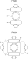
- FIG. 8 is a view illustrating a stabilizer manufacturing method according to an embodiment of the present invention.
- a first pressing member 31 and a second pressing member 32 facing each other across the first reduced diameter portion 22 sandwich and press the first reduced diameter portion 22 so as to form the first end 11.
- the second end 12 is formed by sandwiching and pressing the second reduced diameter portion 23 by the first pressing member 31 and the second pressing member 32.
- the first pressing member 31 and the second pressing member 32 are movable by driving of an actuator, for example.
- the first pressing member 31 and the second pressing member 32 are positioned by a block that restricts the pressing amounts of the first pressing member 31 and the second pressing member 32.
- This block is disposed at a position where movement amounts of the first pressing member 31 and the second pressing member 32 by the actuator can be forcibly stopped and at a position not interfering with the tubular member 20.
- the wall thicknesses of the first reduced diameter portion 22 and the second reduced diameter portion 23 increase after the processing.
- the volume corresponding to the reduced diameter portion is allocated to the length and the wall thickness. This increases the length and the wall thickness.
- the first end 11 and the second end 12 are equivalent to or greater than the wall thickness T 21 of the central portion 21, the wall thickness (wall thickness T 22 ) of the first reduced diameter portion 22, and the wall thickness of the second reduced diameter portion 23. Since the central portion 21 corresponds to the main body 10, the wall thicknesses of the first end 11 and the second end 12 are equivalent to or greater than the wall thickness of the main body 10.
- the outer diameters of the first reduced diameter portion 22 and the second reduced diameter portion 23 are reduced with respect to the central portion 21, and this leads to suppression of an increase in the maximum widths of the first end 11 and the second end 12 with respect to the outer diameter of the main body 10 in the direction perpendicular to each extending direction of the first end 11 and the second end 12.
- the diameter of the reduced diameter portion is designed after obtaining the cross-sectional area in a case of the width equal to or less than the width of the end to be fabricated.
- a narrow portion being derived from the reduced diameter portion and in which the width of a part is reduced, formed on the main body 10 side of the first end 11 (refer to FIG. 3 ).
- a narrow portion in which the width is partially reduced is also formed in the second end 12.
- the first end 11 and the second end 12 of the stabilizer 1 are formed using the tubular member 20, which includes: the central portion 21; and both ends (the first reduced diameter portion 22 and the second reduced diameter portion 23) having an outer diameter reduced with respect to the central portion 21 and having a wall thickness equivalent to the wall thickness of the central portion 21.
- the tubular member 20 which includes: the central portion 21; and both ends (the first reduced diameter portion 22 and the second reduced diameter portion 23) having an outer diameter reduced with respect to the central portion 21 and having a wall thickness equivalent to the wall thickness of the central portion 21.
- FIG. 9 is a view illustrating a stabilizer manufacturing method according to the modification of the embodiment of the present invention.
- the first reduced diameter portion 22 is sandwiched and pressed by the first pressing member 31 and the second pressing member 32 facing each other across the first reduced diameter portion 22 and also pressed by a third pressing member 33 and a fourth pressing member 34 facing each other across the first reduced diameter portion 22 and facing each other in a direction orthogonal to the facing direction of the first pressing member 31 and the second pressing member 32, thereby forming the first and second ends.
- the reduced diameter portions are simultaneously pressed by the first pressing member 31 to the fourth pressing member 34 in two directions orthogonal to each other.
- the first pressing member 31 and the second pressing member 32 come into contact with the tubular member 20 earlier than the third pressing member 33 and the fourth pressing member 34, and the third pressing member 33 and the fourth pressing member 34 abut on the first pressing member 31 and the second pressing member 32, thereby restricting the pressing amounts by the third pressing member 33 and the fourth pressing member 34.
- the first pressing member 31, the second pressing member 32, the third pressing member 33, and the fourth pressing member 34 are movable by the driving of an actuator, for example.
- the pressing is performed while maintaining the wall thickness of the first reduced diameter portion 22 and the second reduced diameter portion 23.
- the pressing amounts of the first pressing member 31 and the second pressing member 32 are restricted by the above-described block.
- the movement amounts of the third pressing member 33 and the fourth pressing member 34 are restricted by abutting on the first pressing member 31 and/or the second pressing member 32.
- FIG. 10 is a plan view illustrating an end surface of the stabilizer according to the modification of the embodiment of the present invention.
- the plan view illustrated in FIG. 10 corresponds to a view of the stabilizer 1 as viewed in the direction of arrow C illustrated in FIG. 3 .
- a first end 11A according to the modification includes a flat portion 11e having a flat shape.
- the flat portion 11e has a hole (corresponding to the above-described hole 11b) penetrating in the thickness direction.
- the wall thickness of the main body 10 and the wall thickness of the first end 11A are equivalent to or substantially equal to each other.
- the first end 11A includes planar portions 11f to 11i.
- the planar portions 11f and 11g make planes perpendicular to the planar portions 11h and 11i.
- the planar regions of the planar portions 11f and 11g can be increased as compared with the planar regions of the planar portions 11c and 11d according to the embodiment.
- the first end (first end 11A) and the second end of the stabilizer 1 are formed using the tubular member 20 (refer to FIG. 6 ), which includes: the central portion 21; and both ends (the first reduced diameter portion 22 and the second reduced diameter portion 23) having an outer diameter reduced with respect to the central portion 21 and having a wall thickness equivalent to the wall thickness of the central portion.
- the tubular member 20 which includes: the central portion 21; and both ends (the first reduced diameter portion 22 and the second reduced diameter portion 23) having an outer diameter reduced with respect to the central portion 21 and having a wall thickness equivalent to the wall thickness of the central portion.
- both ends of the tubular member 20 are pressed in two directions orthogonal to each other to form a flat-plate shape, making it possible to form an end having an increased planar region while suppressing an increase in width as compared with the first and second ends according to the embodiment.
- the timing is not limited thereto, and the timings of sandwiching may be different from each other.
- the present invention should not be limited only by the above-described embodiments.
- the present invention is applicable to a product in which the end is required to be formed into a flat-plate shape and the width of the flat plate portion is required to be suppressed.
- the present invention can include various embodiments and the like not described herein, and various design changes and the like can be made without departing from the technical concept specified by the claims.
- the stabilizer manufacturing method, the stabilizer, and the stabilizer manufacturing base tubular member according to the present invention are suitable for achieving a sufficient strength in both ends of the stabilizer and weight reduction of the stabilizer.
Landscapes
- Engineering & Computer Science (AREA)
- Mechanical Engineering (AREA)
- Vehicle Body Suspensions (AREA)
Abstract
Description
- The present invention relates to a stabilizer manufacturing method, a stabilizer, and a stabilizer manufacturing base tubular member.
- A stabilizer used in a vehicle or the like is attached to the vehicle to stabilize the posture of the vehicle. The stabilizer is formed by deforming a solid rod-shaped member, for example (refer to
Patent Literature 1, for example). The stabilizer has its two ends connected to the vehicle, with each connecting portion having a planar shape. Each of the ends of the stabilizer is formed into a flat-plate shape by crushing a bar-shaped member, and then a hole for insertion of a bolt or the like is formed on each of the flat-plate shaped ends. At this time, both side surface portions of the flat-plate portions are cut off to adjust the width of the flat-plate portions. - Meanwhile, in order to reduce the weight of the vehicle, there is an increasing demand for weight reduction of the stabilizer. An example of implementing the weight reduction of the stabilizer is changing the material used for formation from a solid rod-like member to a hollow tubular member.
- Patent Literature 1:
JP 10-193944 A - However, in a case where the material is changed to a tubular member, cutting off both side surface portions of the both ends, which have been formed into the flat-plate portions, might reduce the wall thickness of the side surface portions or lose the side surface portions by the cutting. A failure to ensure a sufficient wall thickness of the side surface portion would lower the strength of the stabilizer.
- The present invention has been made in view of the above, and aims to provide a stabilizer manufacturing method, a stabilizer, and a stabilizer manufacturing base tubular member, capable of achieving a sufficient strength in both ends of the stabilizer and weight reduction of the stabilizer.
- To solve the above-described problem and achieve the object, a stabilizer manufacturing method according to the present invention includes forming a first end and a second end of a stabilizer by processing a tubular member, wherein the tubular member includes: a central portion having a tubular shape; a first reduced diameter portion having a tubular shape and provided on one end side of the central portion, the first reduced diameter portion having a wall thickness equivalent to a wall thickness of the central portion and having a diameter smaller than a diameter of the central portion; a second reduced diameter portion having a tubular shape and provided on the other end side of the central portion, the second reduced diameter portion having a wall thickness equivalent to the wall thickness of the central portion and having a diameter smaller than the diameter of the central portion; a first connecting portion having a conical shape and connecting the central portion and the first reduced diameter portion to each other; and a second connecting portion having a conical shape and connecting the central portion and the second reduced diameter portion to each other, the first end and the second end constitutes both ends of the stabilizer and each has a wall thickness equivalent to a wall thickness of a main body of the stabilizer, and the first end and the second end are formed by sandwiching and pressing each of the first reduced diameter portion and the second reduced diameter portion by a pair of first pressing members.
- Moreover, in the above-described stabilizer manufacturing method according to the present invention, the first and second ends having the wall thickness equivalent to the wall thickness of the main body are formed by sandwiching and pressing each of the first and second reduced diameter portions by the pair of first pressing members and a pair of second pressing members having different facing directions from facing directions of the pair of first pressing members.
- Moreover, in the above-described stabilizer manufacturing method according to the present invention, the pair of first pressing members and the pair of second pressing members simultaneously sandwich and press the first and second reduced diameter portions.
- Moreover, a stabilizer according to the present invention is formed by using a tubular member including: a central portion having a tubular shape; a first reduced diameter portion having a tubular shape and provided on one end side of the central portion, the first reduced diameter portion having a wall thickness equivalent to a wall thickness of the central portion and having a diameter smaller than a diameter of the central portion; a second reduced diameter portion having a tubular shape and provided on the other end side of the central portion, the second reduced diameter portion having a wall thickness equivalent to the wall thickness of the central portion and having a diameter smaller than the diameter of the central portion; a first connecting portion having a conical shape and connecting the central portion and the first reduced diameter portion to each other; and a second connecting portion having a conical shape and connecting the central portion and the second reduced diameter portion to each other, and includes: a main body having a tubular shape; a first end provided on one end side of the main body and having a flat plate shape, the first end formed to have an annular shape having a wall thickness equivalent to a wall thickness of the main body; and a second end provided on the other end side of the main body and having a flat plate shape, the second end formed to have an annular shape having a wall thickness equivalent to the wall thickness of the main body, wherein each of the first and second ends includes first and second planar portions having planar shapes formed on opposite sides to each other.
- Moreover, in the above-described stabilizer according to the present invention, the first and second ends further include third and fourth planar portions formed on opposite sides to each other and having planar shapes and each positioned at joining portions of the first and second planar portions.
- Moreover, a stabilizer manufacturing base tubular member according to the present invention includes: a central portion having a tubular shape; a first reduced diameter portion having a tubular shape and provided on one end side of the central portion, the first reduced diameter portion having a wall thickness equivalent to a wall thickness of the central portion and having a diameter smaller than a diameter of the central portion; a second reduced diameter portion having a tubular shape and provided on the other end side of the central portion, the second reduced diameter portion having a wall thickness equivalent to the wall thickness of the central portion and having a diameter smaller than the diameter of the central portion; a first connecting portion having a conical shape and connecting the central portion and the first reduced diameter portion to each other; and a second connecting portion having a conical shape and connecting the central portion and the second reduced diameter portion to each other.
- According to the present invention, it is possible to achieve a sufficient strength in both ends of the stabilizer and weight reduction of the stabilizer.
-
-
FIG. 1 is a perspective view illustrating an example of a suspension mechanism including a stabilizer according to an embodiment of the present invention. -
FIG. 2 is a plan view illustrating a configuration of the stabilizer illustrated inFIG. 1 . -
FIG. 3 is a plan view of the stabilizer in a region R illustrated inFIG. 2 as viewed in the direction of arrow A. -
FIG. 4 is a cross-sectional view taken along line B-B illustrated inFIG. 3 . -
FIG. 5 is a plan view illustrating an end surface of the stabilizer as viewed in the direction of arrow C illustrated inFIG. 3 . -
FIG. 6 is a perspective view illustrating a configuration of a tubular member for fabricating the stabilizer according to an embodiment of the present invention. -
FIG. 7 is a plan view illustrating an end surface of the tubular member as viewed in the direction of arrow D illustrated inFIG. 6 . -
FIG. 8 is a view illustrating a stabilizer manufacturing method according to an embodiment of the present invention. -
FIG. 9 is a view illustrating a stabilizer manufacturing method according to a modification of the embodiment of the present invention. -
FIG. 10 is a plan view illustrating an end surface of the stabilizer according to the modification of the embodiment of the present invention. - Hereinafter, modes for carrying out the present invention (hereinafter, referred to as "embodiment") will be described with reference to the accompanying drawings. Note that the drawings are schematic, and the relationship between the thickness and the width of each portion, the ratio of the thickness of each portion, and the like may be different from actual measurements, and portions having different dimensional relationships and ratios may be included in individual drawings.
-
FIG. 1 is a perspective view illustrating an example of a suspension mechanism including a stabilizer according to an embodiment of the present invention. Asuspension mechanism 100 illustrated inFIG. 1 includes astabilizer 1,suspensions links suspensions suspension mechanism 100 is provided in an automobile, thesuspensions tires 111 and 112 (for example, front wheels) so as to absorb vibration transmitted from thetires suspensions stabilizer 1 via thelinks -
FIG. 2 is a plan view illustrating a configuration of the stabilizer illustrated inFIG. 1 .FIG. 3 is a plan view of the stabilizer in a region R illustrated inFIG. 2 as viewed in the direction of arrow A.FIG. 4 is a cross-sectional view taken along line B-B illustrated inFIG. 3 .FIG. 5 is a plan view illustrating an end surface of the stabilizer as viewed in the direction of arrow C illustrated inFIG. 3 . - The
stabilizer 1 is formed using a tubular member made of metal or various fibers (for example, carbon fibers). Thestabilizer 1 includes: amain body 10; afirst end 11 continuous with one end of themain body 10; and asecond end 12 continuous with the other end of themain body 10. - The
main body 10 has its central portion extending in a straight line shape, and has its both ends formed to be bent. - The
first end 11 has aflat portion 11a having a flat shape. Theflat portion 11a has ahole 11b penetrating in the thickness direction (refer toFIGS. 3 and4 ). As illustrated inFIG. 4 , a wall thickness T10 of themain body 10 and a wall thickness T11 of thefirst end 11 are equivalent to or substantially equal to each other. The term "substantially equal" as used herein represents equality including a difference in the degree of manufacturing error. Thefirst end 11 has a closed annular shape (shape in which inner peripheral surfaces of the portions are in contact with each other) in plan view in the direction of arrow C (refer toFIG. 5 ). The shape of the portion, in the plan view, is not limited to the closed annular shape illustrated inFIG. 5 , and may be an annular shape having a hollow space. At this time, a closed annular shape is preferable from the viewpoint of achieving a sufficient strength of thefirst end 11. - In addition, the
first end 11 includesplanar portions first end 11 is attached to an automobile or the like, theplanar portion 11c comes into contact with a fastening member such as a bolt head, a washer, or a nut, for example. The surface of thestabilizer 1 with which the fastening member comes into contact is preferably a planar surface. - The
second end 12 has a shape similar to the shape of thefirst end 11. Thesecond end 12 has a flat portion having a flat shape, and has a hole penetrating in the thickness direction. Thesecond end 12 has a wall thickness equivalent to or substantially equal to a wall thickness of themain body 10. - Subsequently, end fabrication processing of the
stabilizer 1 described above will be described with reference toFIGS. 6 to 8 . Thestabilizer 1 is fabricated by processing a base material. In the present embodiment, a tubular base material is bent, and then, both ends of the material are processed into flat plate shapes. Thereafter, a through hole is formed at each end. -
FIG. 6 is a perspective view illustrating a configuration of a tubular member for fabricating the stabilizer according to an embodiment of the present invention.FIG. 7 is a plan view illustrating an end surface of the tubular member as viewed in the direction of arrow D illustrated inFIG. 6 . Atubular member 20 to be a base material of thestabilizer 1 includes: acentral portion 21 having a tubular shape; a first reduceddiameter portion 22 provided on one end side of thecentral portion 21 and having a tubular shape with a diameter smaller than the diameter of thecentral portion 21; a second reduceddiameter portion 23 provided on the other end side of thecentral portion 21 and having a tubular shape with a diameter smaller than the diameter of thecentral portion 21; a first connectingportion 24 having a conical shape and connecting thecentral portion 21 and the first reduceddiameter portion 22 to each other; and a second connectingportion 25 having a conical shape and connecting thecentral portion 21 and the second reduceddiameter portion 23 to each other. Thecentral portion 21, the first reduceddiameter portion 22, and the second reduceddiameter portion 23 each extend while maintaining a uniform outer diameter and inner diameter. - In the
tubular member 20, the first reduceddiameter portion 22 and the second reduceddiameter portion 23 are formed by processing both ends of a member having a uniform outer diameter and inner diameter. The processing at this time can use swaging, for example. The swaging may be processing using a core metal or processing not using a core metal. The first reduceddiameter portion 22 has a wall thickness equivalent to the wall thickness of thecentral portion 21. As illustrated inFIG. 7 , thetubular member 20 is formed such that a wall thickness T21 of thecentral portion 21 and a wall thickness T22 of the first reduceddiameter portion 22 are equivalent to each other or satisfy T21 < T22. The term "equivalent" as used herein includes a case of being equal to each other and a case with a manufacturing error. - The shape and wall thickness of the second reduced
diameter portion 23 are also similar to the case of the first reduceddiameter portion 22. - In the present embodiment, the reduced diameter portion is sandwiched and pressed by the pair of pressing members, thereby forming the end of the
stabilizer 1.FIG. 8 is a view illustrating a stabilizer manufacturing method according to an embodiment of the present invention. As illustrated inFIG. 8 , a first pressingmember 31 and a second pressingmember 32 facing each other across the first reduceddiameter portion 22 sandwich and press the first reduceddiameter portion 22 so as to form thefirst end 11. Similarly, thesecond end 12 is formed by sandwiching and pressing the second reduceddiameter portion 23 by the first pressingmember 31 and the second pressingmember 32. The first pressingmember 31 and the second pressingmember 32 are movable by driving of an actuator, for example. The first pressingmember 31 and the second pressingmember 32 are positioned by a block that restricts the pressing amounts of the first pressingmember 31 and the second pressingmember 32. This block is disposed at a position where movement amounts of the first pressingmember 31 and the second pressingmember 32 by the actuator can be forcibly stopped and at a position not interfering with thetubular member 20. - When the
first end 11 and thesecond end 12 are formed by the first pressingmember 31 and the second pressingmember 32, pressing is performed while maintaining the wall thickness of the first reduceddiameter portion 22 and the second reduceddiameter portion 23. When pressed, the wall thicknesses of the first reduceddiameter portion 22 and the second reduceddiameter portion 23 increase after the processing. Here, in the case of not using a core rod plug to be inserted inside during processing, since the volumes of the reduced diameter portion before and after processing are the same, the volume corresponding to the reduced diameter portion is allocated to the length and the wall thickness. This increases the length and the wall thickness. Therefore, thefirst end 11 and thesecond end 12 are equivalent to or greater than the wall thickness T21 of thecentral portion 21, the wall thickness (wall thickness T22) of the first reduceddiameter portion 22, and the wall thickness of the second reduceddiameter portion 23. Since thecentral portion 21 corresponds to themain body 10, the wall thicknesses of thefirst end 11 and thesecond end 12 are equivalent to or greater than the wall thickness of themain body 10. - In addition, the outer diameters of the first reduced
diameter portion 22 and the second reduceddiameter portion 23 are reduced with respect to thecentral portion 21, and this leads to suppression of an increase in the maximum widths of thefirst end 11 and thesecond end 12 with respect to the outer diameter of themain body 10 in the direction perpendicular to each extending direction of thefirst end 11 and thesecond end 12. - Here, regarding the first reduced
diameter portion 22 and the second reduceddiameter portion 23, since the cross-sectional area of the reduced diameter portion is to be equal to the cross-sectional area after processing (crushing), the diameter of the reduced diameter portion is designed after obtaining the cross-sectional area in a case of the width equal to or less than the width of the end to be fabricated. - Furthermore, by pressing the first reduced
diameter portion 22 and the second reduceddiameter portion 23, for example, there is provided a narrow portion, being derived from the reduced diameter portion and in which the width of a part is reduced, formed on themain body 10 side of the first end 11 (refer toFIG. 3 ). Similarly, a narrow portion in which the width is partially reduced is also formed in thesecond end 12. - In the present embodiment, the
first end 11 and thesecond end 12 of thestabilizer 1 are formed using thetubular member 20, which includes: thecentral portion 21; and both ends (the first reduceddiameter portion 22 and the second reduced diameter portion 23) having an outer diameter reduced with respect to thecentral portion 21 and having a wall thickness equivalent to the wall thickness of thecentral portion 21. According to the present embodiment, by forming thefirst end 11 and thesecond end 12 by pressing the material into a flat-plate shape while maintaining the wall thicknesses of the first reduceddiameter portion 22 and the second reduceddiameter portion 23, it is possible to achieve a sufficient strength of both ends by suppressing the thinning and to reduce the weight of the stabilizer by using the tubular shape. - Next, a modification of the embodiment of the present invention will be described with reference to
FIGS. 9 and10 . Note that the same components as those in the embodiment are denoted by the same reference numerals. The present modification is different from the above-described embodiment in a method of forming thefirst end 11 and thesecond end 12. - In the present modification, the reduced diameter portion is sandwiched and pressed by two pairs of pressing members facing each other in different directions, thereby forming the end of the
stabilizer 1.FIG. 9 is a view illustrating a stabilizer manufacturing method according to the modification of the embodiment of the present invention. As illustrated inFIG. 9 , the first reduceddiameter portion 22 is sandwiched and pressed by the first pressingmember 31 and the second pressingmember 32 facing each other across the first reduceddiameter portion 22 and also pressed by a third pressingmember 33 and a fourth pressingmember 34 facing each other across the first reduceddiameter portion 22 and facing each other in a direction orthogonal to the facing direction of the first pressingmember 31 and the second pressingmember 32, thereby forming the first and second ends. At this time, the reduced diameter portions are simultaneously pressed by the first pressingmember 31 to the fourth pressingmember 34 in two directions orthogonal to each other. At this time, for example, the first pressingmember 31 and the second pressingmember 32 come into contact with thetubular member 20 earlier than the third pressingmember 33 and the fourth pressingmember 34, and the third pressingmember 33 and the fourth pressingmember 34 abut on the first pressingmember 31 and the second pressingmember 32, thereby restricting the pressing amounts by the third pressingmember 33 and the fourth pressingmember 34. The first pressingmember 31, the second pressingmember 32, the third pressingmember 33, and the fourth pressingmember 34 are movable by the driving of an actuator, for example. - In the modification, when the first and second ends are formed by the first pressing
member 31 to the fourth pressingmember 34, the pressing is performed while maintaining the wall thickness of the first reduceddiameter portion 22 and the second reduceddiameter portion 23. Here, the pressing amounts of the first pressingmember 31 and the second pressingmember 32 are restricted by the above-described block. The movement amounts of the third pressingmember 33 and the fourth pressingmember 34 are restricted by abutting on the first pressingmember 31 and/or the second pressingmember 32. - The first and second ends formed by the pressing method of the modification will be described using the first end as an example.
FIG. 10 is a plan view illustrating an end surface of the stabilizer according to the modification of the embodiment of the present invention. The plan view illustrated inFIG. 10 corresponds to a view of thestabilizer 1 as viewed in the direction of arrow C illustrated inFIG. 3 . Afirst end 11A according to the modification includes aflat portion 11e having a flat shape. Theflat portion 11e has a hole (corresponding to the above-describedhole 11b) penetrating in the thickness direction. In addition, the wall thickness of themain body 10 and the wall thickness of thefirst end 11A are equivalent to or substantially equal to each other. - The
first end 11A includesplanar portions 11f to 11i. Theplanar portions planar portions planar portions planar portions - In the present modification, similarly to the embodiment, the first end (
first end 11A) and the second end of thestabilizer 1 are formed using the tubular member 20 (refer toFIG. 6 ), which includes: thecentral portion 21; and both ends (the first reduceddiameter portion 22 and the second reduced diameter portion 23) having an outer diameter reduced with respect to thecentral portion 21 and having a wall thickness equivalent to the wall thickness of the central portion. According to the present modification, by forming the first and second ends by pressing the material into flat-plate shapes while maintaining the wall thicknesses of the first reduceddiameter portion 22 and the second reduceddiameter portion 23, it is possible to achieve a sufficient strength of both ends of the stabilizer by suppressing the thinning and to reduce the weight of the stabilizer by using the tubular shape. - In addition, in the present modification, both ends of the
tubular member 20 are pressed in two directions orthogonal to each other to form a flat-plate shape, making it possible to form an end having an increased planar region while suppressing an increase in width as compared with the first and second ends according to the embodiment. With this configuration, it is possible to increase a contact region with a fastening member at the first and second ends, and as a result, it is possible to increase the degree of freedom of applicable types of the fastening member and to stabilize the contact state with the fastening member. - Although the above-described modification is an example in which the first pressing
member 31 and the second pressingmember 32, and the third pressingmember 33 and the fourth pressingmember 34, simultaneously sandwich the reduced diameter portion, the timing is not limited thereto, and the timings of sandwiching may be different from each other. - Although the embodiments for carrying out the present invention have been described so far, the present invention should not be limited only by the above-described embodiments. For example, the present invention is applicable to a product in which the end is required to be formed into a flat-plate shape and the width of the flat plate portion is required to be suppressed.
- As described above, the present invention can include various embodiments and the like not described herein, and various design changes and the like can be made without departing from the technical concept specified by the claims.
- As described above, the stabilizer manufacturing method, the stabilizer, and the stabilizer manufacturing base tubular member according to the present invention are suitable for achieving a sufficient strength in both ends of the stabilizer and weight reduction of the stabilizer.
-
- 1 STABILIZER
- 10 MAIN BODY
- 11, 11A FIRST END
- 11a, 11e FLAT PORTION
- 11b HOLE
- 11c, 11d, 11f to 11i PLANAR PORTION
- 12 SECOND END
- 20 TUBULAR MEMBER
- 21 CENTRAL PORTION
- 22 FIRST REDUCED DIAMETER PORTION
- 23 SECOND REDUCED DIAMETER PORTION
- 24 FIRST CONNECTING PORTION
- 25 SECOND CONNECTING PORTION
- 31 FIRST PRESSING MEMBER
- 32 SECOND PRESSING MEMBER
- 33 THIRD PRESSING MEMBER
- 34 FOURTH PRESSING MEMBER
Claims (6)
- A stabilizer manufacturing method comprisingforming a first end and a second end of a stabilizer by processing a tubular member, whereinthe tubular member includes:a central portion having a tubular shape;a first reduced diameter portion having a tubular shape and provided on one end side of the central portion, the first reduced diameter portion having a wall thickness equivalent to a wall thickness of the central portion and having a diameter smaller than a diameter of the central portion;a second reduced diameter portion having a tubular shape and provided on the other end side of the central portion, the second reduced diameter portion having a wall thickness equivalent to the wall thickness of the central portion and having a diameter smaller than the diameter of the central portion;a first connecting portion having a conical shape and connecting the central portion and the first reduced diameter portion to each other; anda second connecting portion having a conical shape and connecting the central portion and the second reduced diameter portion to each other,the first end and the second end constitutes both ends of the stabilizer and each has a wall thickness equivalent to a wall thickness of a main body of the stabilizer, andthe first end and the second end are formed by sandwiching and pressing each of the first reduced diameter portion and the second reduced diameter portion by a pair of first pressing members.
- The stabilizer manufacturing method according to claim 1, wherein the first and second ends having the wall thickness equivalent to the wall thickness of the main body are formed by sandwiching and pressing each of the first and second reduced diameter portions by the pair of first pressing members and a pair of second pressing members having different facing directions from facing directions of the pair of first pressing members.
- The stabilizer manufacturing method according to claim 2, wherein the pair of first pressing members and the pair of second pressing members simultaneously sandwich and press the first and second reduced diameter portions.
- A stabilizer formed by using a tubular member including: a central portion having a tubular shape; a first reduced diameter portion having a tubular shape and provided on one end side of the central portion, the first reduced diameter portion having a wall thickness equivalent to a wall thickness of the central portion and having a diameter smaller than a diameter of the central portion; a second reduced diameter portion having a tubular shape and provided on the other end side of the central portion, the second reduced diameter portion having a wall thickness equivalent to the wall thickness of the central portion and having a diameter smaller than the diameter of the central portion; a first connecting portion having a conical shape and connecting the central portion and the first reduced diameter portion to each other; and a second connecting portion having a conical shape and connecting the central portion and the second reduced diameter portion to each other, the stabilizer comprising:a main body having a tubular shape;a first end provided on one end side of the main body and having a flat plate shape, the first end formed to have an annular shape having a wall thickness equivalent to a wall thickness of the main body; anda second end provided on the other end side of the main body and having a flat plate shape, the second end formed to have an annular shape having a wall thickness equivalent to the wall thickness of the main body,wherein each of the first and second ends includes first and second planar portions having planar shapes formed on opposite sides to each other.
- The stabilizer according to claim 4, wherein the first and second ends further include third and fourth planar portions formed on opposite sides to each other and having planar shapes and each positioned at joining portions of the first and second planar portions.
- A stabilizer manufacturing base tubular member, comprising:a central portion having a tubular shape;a first reduced diameter portion having a tubular shape and provided on one end side of the central portion, the first reduced diameter portion having a wall thickness equivalent to a wall thickness of the central portion and having a diameter smaller than a diameter of the central portion;a second reduced diameter portion having a tubular shape and provided on the other end side of the central portion, the second reduced diameter portion having a wall thickness equivalent to the wall thickness of the central portion and having a diameter smaller than the diameter of the central portion;a first connecting portion having a conical shape and connecting the central portion and the first reduced diameter portion to each other; anda second connecting portion having a conical shape and connecting the central portion and the second reduced diameter portion to each other.
Applications Claiming Priority (2)
| Application Number | Priority Date | Filing Date | Title |
|---|---|---|---|
| JP2021210187A JP7413340B2 (en) | 2021-12-24 | 2021-12-24 | Stabilizer manufacturing method |
| PCT/JP2022/047442 WO2023120665A1 (en) | 2021-12-24 | 2022-12-22 | Stabilizer manufacturing method, stabilizer, and tubular member for manufacturing stabilizer |
Publications (2)
| Publication Number | Publication Date |
|---|---|
| EP4454907A1 true EP4454907A1 (en) | 2024-10-30 |
| EP4454907A4 EP4454907A4 (en) | 2025-03-12 |
Family
ID=86902753
Family Applications (1)
| Application Number | Title | Priority Date | Filing Date |
|---|---|---|---|
| EP22911367.5A Pending EP4454907A4 (en) | 2021-12-24 | 2022-12-22 | METHOD FOR MANUFACTURING STABILIZER, STABILIZER AND TUBULAR ELEMENT FOR MANUFACTURING STABILIZER |
Country Status (5)
| Country | Link |
|---|---|
| EP (1) | EP4454907A4 (en) |
| JP (1) | JP7413340B2 (en) |
| CN (1) | CN118401387A (en) |
| MX (1) | MX2024006924A (en) |
| WO (1) | WO2023120665A1 (en) |
Family Cites Families (18)
| Publication number | Priority date | Publication date | Assignee | Title |
|---|---|---|---|---|
| JPS55153208U (en) * | 1979-04-20 | 1980-11-05 | ||
| JPS5854246Y2 (en) * | 1980-02-19 | 1983-12-10 | 中央発條株式会社 | Hollow stabilizer for wheel suspension |
| JPS57124533A (en) * | 1981-01-23 | 1982-08-03 | Chuo Spring Co Ltd | Forming method for eye part of hollow stabilizer for motorcar |
| JPS58133909A (en) * | 1982-02-01 | 1983-08-09 | Nhk Spring Co Ltd | End forming method of stabilizer for vehicle suspension |
| JPH033378Y2 (en) * | 1986-08-29 | 1991-01-29 | ||
| US4781054A (en) * | 1986-12-19 | 1988-11-01 | Rockwell International Suspension Systems Company | Apparatus for bending and forming heated tubular workpieces |
| JPH02283519A (en) * | 1989-04-24 | 1990-11-21 | Nhk Spring Co Ltd | Hollow stabilizer for vehicle |
| JP3168236B2 (en) * | 1994-02-28 | 2001-05-21 | 日本発条株式会社 | Hollow stabilizer for vehicles and method of manufacturing the same |
| JP3909531B2 (en) | 1997-01-08 | 2007-04-25 | 中央発條株式会社 | Automotive stabilizer |
| JP3848556B2 (en) * | 2001-10-18 | 2006-11-22 | 日本発条株式会社 | Hollow stabilizer |
| JP2007064266A (en) * | 2005-08-29 | 2007-03-15 | Ntn Corp | Hollow shaft |
| JP2007320344A (en) * | 2006-05-30 | 2007-12-13 | Mitsubishi Steel Mfg Co Ltd | Hollow stabilizer |
| JP2007320343A (en) * | 2006-05-30 | 2007-12-13 | Mitsubishi Steel Mfg Co Ltd | Hollow stabilizer |
| JP2008143313A (en) * | 2006-12-08 | 2008-06-26 | Mitsubishi Steel Mfg Co Ltd | Hollow stabilizer |
| JP2009190065A (en) * | 2008-02-15 | 2009-08-27 | F Tech:Kk | Caulking structure using color members |
| JP4714252B2 (en) * | 2008-09-25 | 2011-06-29 | 三菱製鋼株式会社 | Hollow stabilizer |
| DE102013003300A1 (en) * | 2013-02-28 | 2014-08-28 | Bpw Bergische Achsen Kg | Chassis for a commercial vehicle, axle body and method for producing an axle body |
| JP2014210051A (en) * | 2013-04-18 | 2014-11-13 | 日本発條株式会社 | Method for manufacturing ball-hitting bat |
-
2021
- 2021-12-24 JP JP2021210187A patent/JP7413340B2/en active Active
-
2022
- 2022-12-22 MX MX2024006924A patent/MX2024006924A/en unknown
- 2022-12-22 CN CN202280082717.8A patent/CN118401387A/en active Pending
- 2022-12-22 WO PCT/JP2022/047442 patent/WO2023120665A1/en not_active Ceased
- 2022-12-22 EP EP22911367.5A patent/EP4454907A4/en active Pending
Also Published As
| Publication number | Publication date |
|---|---|
| WO2023120665A1 (en) | 2023-06-29 |
| JP7413340B2 (en) | 2024-01-15 |
| EP4454907A4 (en) | 2025-03-12 |
| JP2023094719A (en) | 2023-07-06 |
| CN118401387A (en) | 2024-07-26 |
| MX2024006924A (en) | 2024-06-20 |
Similar Documents
| Publication | Publication Date | Title |
|---|---|---|
| US8752850B2 (en) | Arm component for vehicles and its manufacturing method | |
| US6298962B1 (en) | Member for arm | |
| US6817382B2 (en) | Pile member | |
| US20070075518A1 (en) | Torsion beam suspension apparatus | |
| US8490987B2 (en) | Stabilizer bar | |
| US20150224842A1 (en) | Vehicular arm component and manufacturing method the same | |
| US20110252595A1 (en) | Fitting member | |
| JPWO2014148513A1 (en) | Suspension link and manufacturing method thereof | |
| EP4454906A1 (en) | Method for manufacturing stabilizer, and stabilizer | |
| US20050124231A1 (en) | Female terminal | |
| JP7413340B2 (en) | Stabilizer manufacturing method | |
| KR102937526B1 (en) | suspension arm | |
| JP5053874B2 (en) | Vehicle suspension arm and manufacturing method thereof | |
| JPH0223366B2 (en) | ||
| US6516993B2 (en) | Control rod | |
| JP3937604B2 (en) | Link manufacturing method | |
| EP3524450B1 (en) | Arm component and manufacturing method therefor | |
| EP4501486A1 (en) | Method for manufacturing stabilizer, and base material | |
| JP2001214920A (en) | Member for arm | |
| JP4200869B2 (en) | A-type suspension arm for vehicles | |
| CN219056377U (en) | Front subframe and vehicle having same | |
| JP2001088524A (en) | Link | |
| JP2025091020A (en) | Bonding structure and bonding method | |
| JP2001071089A (en) | Method for manufacturing arm member | |
| JP2002337527A (en) | Suspension bush assembly structure |
Legal Events
| Date | Code | Title | Description |
|---|---|---|---|
| STAA | Information on the status of an ep patent application or granted ep patent |
Free format text: STATUS: THE INTERNATIONAL PUBLICATION HAS BEEN MADE |
|
| PUAI | Public reference made under article 153(3) epc to a published international application that has entered the european phase |
Free format text: ORIGINAL CODE: 0009012 |
|
| STAA | Information on the status of an ep patent application or granted ep patent |
Free format text: STATUS: REQUEST FOR EXAMINATION WAS MADE |
|
| 17P | Request for examination filed |
Effective date: 20240611 |
|
| AK | Designated contracting states |
Kind code of ref document: A1 Designated state(s): AL AT BE BG CH CY CZ DE DK EE ES FI FR GB GR HR HU IE IS IT LI LT LU LV MC ME MK MT NL NO PL PT RO RS SE SI SK SM TR |
|
| A4 | Supplementary search report drawn up and despatched |
Effective date: 20250207 |
|
| RIC1 | Information provided on ipc code assigned before grant |
Ipc: B21D 53/88 20060101ALI20250204BHEP Ipc: B21D 41/04 20060101ALI20250204BHEP Ipc: B60G 21/055 20060101AFI20250204BHEP |
|
| DAV | Request for validation of the european patent (deleted) | ||
| DAX | Request for extension of the european patent (deleted) |