EP4454885A1 - Droplet discharging device and maintenance method - Google Patents
Droplet discharging device and maintenance method Download PDFInfo
- Publication number
- EP4454885A1 EP4454885A1 EP22911399.8A EP22911399A EP4454885A1 EP 4454885 A1 EP4454885 A1 EP 4454885A1 EP 22911399 A EP22911399 A EP 22911399A EP 4454885 A1 EP4454885 A1 EP 4454885A1
- Authority
- EP
- European Patent Office
- Prior art keywords
- droplet discharge
- coloring liquid
- discharge head
- flow rate
- supply
- Prior art date
- Legal status (The legal status is an assumption and is not a legal conclusion. Google has not performed a legal analysis and makes no representation as to the accuracy of the status listed.)
- Pending
Links
Images






Classifications
-
- B—PERFORMING OPERATIONS; TRANSPORTING
- B41—PRINTING; LINING MACHINES; TYPEWRITERS; STAMPS
- B41J—TYPEWRITERS; SELECTIVE PRINTING MECHANISMS, i.e. MECHANISMS PRINTING OTHERWISE THAN FROM A FORME; CORRECTION OF TYPOGRAPHICAL ERRORS
- B41J2/00—Typewriters or selective printing mechanisms characterised by the printing or marking process for which they are designed
- B41J2/005—Typewriters or selective printing mechanisms characterised by the printing or marking process for which they are designed characterised by bringing liquid or particles selectively into contact with a printing material
- B41J2/01—Ink jet
-
- B—PERFORMING OPERATIONS; TRANSPORTING
- B05—SPRAYING OR ATOMISING IN GENERAL; APPLYING FLUENT MATERIALS TO SURFACES, IN GENERAL
- B05B—SPRAYING APPARATUS; ATOMISING APPARATUS; NOZZLES
- B05B15/00—Details of spraying plant or spraying apparatus not otherwise provided for; Accessories
- B05B15/50—Arrangements for cleaning; Arrangements for preventing deposits, drying-out or blockage; Arrangements for detecting improper discharge caused by the presence of foreign matter
-
- B—PERFORMING OPERATIONS; TRANSPORTING
- B05—SPRAYING OR ATOMISING IN GENERAL; APPLYING FLUENT MATERIALS TO SURFACES, IN GENERAL
- B05B—SPRAYING APPARATUS; ATOMISING APPARATUS; NOZZLES
- B05B12/00—Arrangements for controlling delivery; Arrangements for controlling the spray area
- B05B12/004—Arrangements for controlling delivery; Arrangements for controlling the spray area comprising sensors for monitoring the delivery, e.g. by displaying the sensed value or generating an alarm
- B05B12/006—Pressure or flow rate sensors
-
- B—PERFORMING OPERATIONS; TRANSPORTING
- B05—SPRAYING OR ATOMISING IN GENERAL; APPLYING FLUENT MATERIALS TO SURFACES, IN GENERAL
- B05B—SPRAYING APPARATUS; ATOMISING APPARATUS; NOZZLES
- B05B12/00—Arrangements for controlling delivery; Arrangements for controlling the spray area
- B05B12/08—Arrangements for controlling delivery; Arrangements for controlling the spray area responsive to condition of liquid or other fluent material to be discharged, of ambient medium or of target ; responsive to condition of spray devices or of supply means, e.g. pipes, pumps or their drive means
- B05B12/085—Arrangements for controlling delivery; Arrangements for controlling the spray area responsive to condition of liquid or other fluent material to be discharged, of ambient medium or of target ; responsive to condition of spray devices or of supply means, e.g. pipes, pumps or their drive means responsive to flow or pressure of liquid or other fluent material to be discharged
-
- B—PERFORMING OPERATIONS; TRANSPORTING
- B05—SPRAYING OR ATOMISING IN GENERAL; APPLYING FLUENT MATERIALS TO SURFACES, IN GENERAL
- B05B—SPRAYING APPARATUS; ATOMISING APPARATUS; NOZZLES
- B05B13/00—Machines or plants for applying liquids or other fluent materials to surfaces of objects or other work by spraying, not covered by groups B05B1/00 - B05B11/00
- B05B13/002—Machines or plants for applying coating liquids or other fluent materials by inkjet
-
- B—PERFORMING OPERATIONS; TRANSPORTING
- B05—SPRAYING OR ATOMISING IN GENERAL; APPLYING FLUENT MATERIALS TO SURFACES, IN GENERAL
- B05B—SPRAYING APPARATUS; ATOMISING APPARATUS; NOZZLES
- B05B13/00—Machines or plants for applying liquids or other fluent materials to surfaces of objects or other work by spraying, not covered by groups B05B1/00 - B05B11/00
- B05B13/02—Means for supporting work; Arrangement or mounting of spray heads; Adaptation or arrangement of means for feeding work
- B05B13/04—Means for supporting work; Arrangement or mounting of spray heads; Adaptation or arrangement of means for feeding work the spray heads being moved during spraying operation
- B05B13/0431—Means for supporting work; Arrangement or mounting of spray heads; Adaptation or arrangement of means for feeding work the spray heads being moved during spraying operation with spray heads moved by robots or articulated arms, e.g. for applying liquid or other fluent material to three-dimensional [3D] surfaces
-
- B—PERFORMING OPERATIONS; TRANSPORTING
- B05—SPRAYING OR ATOMISING IN GENERAL; APPLYING FLUENT MATERIALS TO SURFACES, IN GENERAL
- B05B—SPRAYING APPARATUS; ATOMISING APPARATUS; NOZZLES
- B05B15/00—Details of spraying plant or spraying apparatus not otherwise provided for; Accessories
- B05B15/50—Arrangements for cleaning; Arrangements for preventing deposits, drying-out or blockage; Arrangements for detecting improper discharge caused by the presence of foreign matter
- B05B15/58—Arrangements for cleaning; Arrangements for preventing deposits, drying-out or blockage; Arrangements for detecting improper discharge caused by the presence of foreign matter preventing deposits, drying-out or blockage by recirculating the fluid to be sprayed from upstream of the discharge opening back to the supplying means
-
- B—PERFORMING OPERATIONS; TRANSPORTING
- B41—PRINTING; LINING MACHINES; TYPEWRITERS; STAMPS
- B41J—TYPEWRITERS; SELECTIVE PRINTING MECHANISMS, i.e. MECHANISMS PRINTING OTHERWISE THAN FROM A FORME; CORRECTION OF TYPOGRAPHICAL ERRORS
- B41J2/00—Typewriters or selective printing mechanisms characterised by the printing or marking process for which they are designed
- B41J2/005—Typewriters or selective printing mechanisms characterised by the printing or marking process for which they are designed characterised by bringing liquid or particles selectively into contact with a printing material
- B41J2/01—Ink jet
- B41J2/135—Nozzles
- B41J2/165—Prevention or detection of nozzle clogging, e.g. cleaning, capping or moistening for nozzles
-
- B—PERFORMING OPERATIONS; TRANSPORTING
- B41—PRINTING; LINING MACHINES; TYPEWRITERS; STAMPS
- B41J—TYPEWRITERS; SELECTIVE PRINTING MECHANISMS, i.e. MECHANISMS PRINTING OTHERWISE THAN FROM A FORME; CORRECTION OF TYPOGRAPHICAL ERRORS
- B41J2/00—Typewriters or selective printing mechanisms characterised by the printing or marking process for which they are designed
- B41J2/005—Typewriters or selective printing mechanisms characterised by the printing or marking process for which they are designed characterised by bringing liquid or particles selectively into contact with a printing material
- B41J2/01—Ink jet
- B41J2/135—Nozzles
- B41J2/165—Prevention or detection of nozzle clogging, e.g. cleaning, capping or moistening for nozzles
- B41J2/16517—Cleaning of print head nozzles
- B41J2/1652—Cleaning of print head nozzles by driving a fluid through the nozzles to the outside thereof, e.g. by applying pressure to the inside or vacuum at the outside of the print head
- B41J2/16526—Cleaning of print head nozzles by driving a fluid through the nozzles to the outside thereof, e.g. by applying pressure to the inside or vacuum at the outside of the print head by applying pressure only
-
- B—PERFORMING OPERATIONS; TRANSPORTING
- B41—PRINTING; LINING MACHINES; TYPEWRITERS; STAMPS
- B41J—TYPEWRITERS; SELECTIVE PRINTING MECHANISMS, i.e. MECHANISMS PRINTING OTHERWISE THAN FROM A FORME; CORRECTION OF TYPOGRAPHICAL ERRORS
- B41J2/00—Typewriters or selective printing mechanisms characterised by the printing or marking process for which they are designed
- B41J2/005—Typewriters or selective printing mechanisms characterised by the printing or marking process for which they are designed characterised by bringing liquid or particles selectively into contact with a printing material
- B41J2/01—Ink jet
- B41J2/17—Ink jet characterised by ink handling
-
- B—PERFORMING OPERATIONS; TRANSPORTING
- B41—PRINTING; LINING MACHINES; TYPEWRITERS; STAMPS
- B41J—TYPEWRITERS; SELECTIVE PRINTING MECHANISMS, i.e. MECHANISMS PRINTING OTHERWISE THAN FROM A FORME; CORRECTION OF TYPOGRAPHICAL ERRORS
- B41J2/00—Typewriters or selective printing mechanisms characterised by the printing or marking process for which they are designed
- B41J2/005—Typewriters or selective printing mechanisms characterised by the printing or marking process for which they are designed characterised by bringing liquid or particles selectively into contact with a printing material
- B41J2/01—Ink jet
- B41J2/17—Ink jet characterised by ink handling
- B41J2/175—Ink supply systems ; Circuit parts therefor
-
- B—PERFORMING OPERATIONS; TRANSPORTING
- B41—PRINTING; LINING MACHINES; TYPEWRITERS; STAMPS
- B41J—TYPEWRITERS; SELECTIVE PRINTING MECHANISMS, i.e. MECHANISMS PRINTING OTHERWISE THAN FROM A FORME; CORRECTION OF TYPOGRAPHICAL ERRORS
- B41J2/00—Typewriters or selective printing mechanisms characterised by the printing or marking process for which they are designed
- B41J2/005—Typewriters or selective printing mechanisms characterised by the printing or marking process for which they are designed characterised by bringing liquid or particles selectively into contact with a printing material
- B41J2/01—Ink jet
- B41J2/17—Ink jet characterised by ink handling
- B41J2/18—Ink recirculation systems
-
- B—PERFORMING OPERATIONS; TRANSPORTING
- B41—PRINTING; LINING MACHINES; TYPEWRITERS; STAMPS
- B41J—TYPEWRITERS; SELECTIVE PRINTING MECHANISMS, i.e. MECHANISMS PRINTING OTHERWISE THAN FROM A FORME; CORRECTION OF TYPOGRAPHICAL ERRORS
- B41J25/00—Actions or mechanisms not otherwise provided for
- B41J25/304—Bodily-movable mechanisms for print heads or carriages movable towards or from paper surface
- B41J25/316—Bodily-movable mechanisms for print heads or carriages movable towards or from paper surface with tilting motion mechanisms relative to paper surface
Definitions
- the disclosed embodiments relate to a droplet discharge device and a maintenance method.
- Inkjet printers and inkjet plotters utilizing an inkjet recording method are known examples of printing apparatuses.
- a droplet discharge head for discharging liquid is installed in such printing apparatuses utilizing an inkjet method.
- Patent Document 1 JP 3629926 B
- a droplet discharge device includes a droplet discharge head, a supply unit, and a controller.
- the droplet discharge head discharges droplets of a coloring liquid.
- the supply unit supplies the coloring liquid to the droplet discharge head.
- the controller controls each unit. During at least a part of a maintenance period after a discharge period in which droplets of the coloring liquid are discharged from the droplet discharge head, the controller controls the supply unit to supply the coloring liquid having a viscosity lower than that of the coloring liquid in the discharge period to the droplet discharge head.
- Embodiments can be appropriately combined so as not to contradict each other in terms of processing content.
- the same portions are denoted by the same reference signs, and redundant explanations are omitted.
- the droplet discharge device disclosed in the present application can be applied to inkjet printers and inkjet plotters that utilize an inkjet recording method, as well as devices that discharge droplets using an inkjet method.
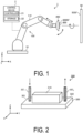
- FIG. 1 is a diagram schematically illustrating a configuration example of the droplet discharge device according to the embodiment.
- a droplet discharge device 1 includes a robotic arm 100, a circulation mechanism 200, a droplet discharge head 300, and a control device 2.
- the robotic arm 100 is assembled on a base 10 mounted on, for example, a horizontal floor surface indoors or outdoors.
- the robotic arm 100 includes an arm portion 110.
- the arm portion 110 is made up of a plurality of parts that are bent and stretched and rotatably assembled.
- the arm portion 110 can, for example, move the droplet discharge head 300 mounted on a tip of the arm portion 110 and change the position, posture, and angle of the droplet discharge head 300.
- the arm portion 110 illustrated in FIG. 1 is not particularly limited to the configuration illustrated in FIG. 1 as long as the arm portion 110 is provided with a degree of freedom with which the droplet discharge head 300 can change the movement, position, posture, angle, and the like as necessary.
- the robotic arm 100 can be moved in a vertical direction (Z axis direction) by the arm portion 110, which, for example, moves the circulation mechanism 200 and the droplet discharge head 300 that are mounted on the tip of the arm portion 110 along a predetermined axis of rotation.
- This allows the circulation mechanism 200 and the droplet discharge head 300 to, for example, assume a posture in which, as illustrated in FIG. 1 , a liquid discharge surface 30SF of the droplet discharge head 300 faces parallel to a spraying surface 50SF of an object 50.
- the robotic arm 100 can, by the arm portion 110, rotate the circulation mechanism 200 and the droplet discharge head 300 that are assembled on the tip of the arm portion 110 about a predetermined axis of rotation, for example. This allows the circulation mechanism 200 and the droplet discharge head 300 to, for example, switch position in a longitudinal direction and in a lateral direction, or to invert an upper position and a lower position.
- the circulation mechanism 200 is installed at a tip portion of the arm portion 110 of the robotic arm 100.
- the circulation mechanism 200 supplies a coloring liquid to the droplet discharge head 300 while controlling the circulation flow rate of the coloring liquid circulating between the circulation mechanism 200 and the droplet discharge head 300.
- the circulation mechanism 200 functions as a supply unit that supplies the coloring liquid to the droplet discharge head 300.
- the droplet discharge head 300 is assembled on the circulation mechanism 200 installed at the tip portion of the arm portion 110 of the robotic arm 100.
- the droplet discharge head 300 functions as a droplet discharge unit that discharges droplets of the coloring liquid to the object 50.
- the coloring liquid is liquid that can be applied to the object 50 to color the object 50.
- the coloring liquid is a pseudoplastic fluid whose viscosity decreases as the shear rate increases is described as an example, but the coloring liquid may not be a pseudoplastic fluid.
- ink, paint, or the like can be used as the coloring liquid.
- the control device 2 is, for example, a computer, and includes the controller 21 such as a processor and a storage 22 such as a memory.
- a control program for controlling a variety of processing to be executed in the droplet discharge device 1 is stored in the storage 22.
- the controller 21 reads out the program stored in the storage 22 and executes the program, thereby controlling the operation of the droplet discharge device 1.
- the program may be recorded in a computer-readable storage medium and installed in the storage 22 of the control device 2 from the storage medium.
- Examples of the computer-readable storage medium include a hard disk (HD), a flexible disk (FD), a compact disk (CD), a magneto-optical disk (MO), and a memory card.
- the present application proposes the droplet discharge device 1 that can reduce the likelihood of discharge failure caused by residue remaining in the droplet discharge head 300.
- FIG. 2 is a perspective view schematically illustrating an outer appearance configuration of the droplet discharge head according to the embodiment.
- FIG. 3 is a plan view of the droplet discharge head according to the embodiment.
- FIG. 4 is a diagram schematically illustrating channels inside the droplet discharge head according to the embodiment.
- the droplet discharge head 300 includes a housing including a box-shaped member 310 and a substantially plate-shaped member 320.
- the housing of the droplet discharge head 300 is provided with a supply port 321 for supplying the coloring liquid to the inside of the droplet discharge head 300 and a recovery port 322 for recovering the coloring liquid from the inside of the droplet discharge head 300.
- a first channel RT 1 for supplying the coloring liquid from the circulation mechanism 200 to the inside of the head is connected to the supply port 321.
- a second channel RT 2 for sending the coloring liquid recovered within the head back to the circulation mechanism 200 is connected to the recovery port 322.
- the droplet discharge head 300 includes a supply reservoir 301, a supply manifold 302, a recovery manifold 303, a recovery reservoir 304, and a discharge unit 305.
- the supply reservoir 301 has an elongated shape extending in a longitudinal direction (Y axis direction) of the droplet discharge head 300 and connects to the supply manifold 302.
- the supply reservoir 301 includes a channel therein. As illustrated in FIG. 4 , the coloring liquid supplied through the first channel RT 1 and the supply port 321 to the supply reservoir 301 and stored in the channel of the supply reservoir 301 is delivered to the supply manifold 302.
- the supply manifold 302 has an elongated shape extending in a lateral direction (X axis direction) of the droplet discharge head 300 to a position before the recovery reservoir 304.
- the supply manifold 302 includes a channel therein in communication with the channel included in the supply reservoir 301 and with the discharge unit 305. As illustrated in FIG. 4 , the coloring liquid delivered from the supply reservoir 301 to the supply manifold 302 is fed from the supply manifold 302 to the discharge unit 305.
- the recovery manifold 303 has an elongated shape extending in the lateral direction (X axis direction) of the droplet discharge head 300 to a position before the supply reservoir 301.
- the recovery manifold 303 has a channel therein in communication with the channel included in the recovery reservoir 304 and with the discharge unit 305. As illustrated in FIG. 4 , the coloring liquid that has not been discharged from the discharge unit 305 to the outside is fed into the recovery manifold 303.
- the recovery reservoir 304 has an elongated shape extending in the longitudinal direction (Y axis direction) of the droplet discharge head 300 and is connected to the recovery manifold 303.
- the recovery reservoir 304 includes a channel therein. As illustrated in FIG. 4 , the coloring liquid fed from the recovery manifold 303 to the recovery reservoir 304 and stored in the channel of the recovery reservoir 304 is fed back through the recovery port 322 and the second channel RT 2 to a tank 201 (see FIG. 6 ).
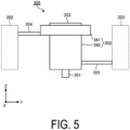
- FIG. 5 is a diagram schematically illustrating a configuration example of the discharge unit according to the embodiment.
- the discharge unit 305 includes a nozzle 351, a pressurizing chamber 352, and a displacement element 353.
- the nozzle 351 is a discharge hole that is open to the discharge surface 30SF (see FIG. 1 ) of the droplet discharge head 300.
- the pressurizing chamber 352 is connected to the nozzle 351.
- the pressurizing chamber 352 includes a body portion 361 to which pressure is applied by the displacement element 353, and a descender 362 serving as a channel connecting the body portion 361 and the nozzle 351.
- the pressurizing chamber 352 and the supply manifold 302 are connected to each other via a separate supply channel 354.
- the coloring liquid delivered from the supply manifold 302 to the discharge unit 305 is supplied through the separate supply channel 354 to the pressurizing chamber 352.
- the pressurizing chamber 352 and the recovery manifold 303 are connected to each other via a separate recovery channel 355.
- the coloring liquid that has not been discharged from the nozzle 351 to the outside is recovered from the pressurizing chamber 352 to the recovery manifold 303.
- the displacement element 353 is located on a surface of the body portion 361 of the pressurizing chamber 352 on a side opposite to the descender 362.
- the displacement element 353 is an element that deforms in response to a predetermined driving signal.
- the displacement element 353 functions as a pressurizing unit that applies pressure to the pressurizing chamber 352 to discharge droplets of the coloring liquid from the nozzle 351. That is, when the displacement element 353 is deformed, pressure (positive pressure and negative pressure) is applied to the pressurizing chamber 352, and droplets of the coloring liquid are discharged from the nozzle 351.
- the displacement element 353 is electrically connected to the control device 2 and is controlled by the control device 2.
- the discharge unit 305 having such a configuration sucks out the coloring liquid from the supply manifold 302 by the negative pressure applied to the pressurizing chamber 352, and discharges the sucked coloring liquid from the nozzle 351 toward the object 50 by the positive pressure applied to the pressurizing chamber 352.
- FIG. 6 is a diagram schematically illustrating the circulation mechanism according to the embodiment.
- the circulation mechanism 200 includes a tank 201, a discharge pump 202, a suction pump 203, a first proportional valve 204, a second proportional valve 205, and a heater 206.
- the circulation mechanism 200 also includes a first pressure sensor 208, a second pressure sensor 209, a third pressure sensor 210, a fourth pressure sensor 211, and a flowmeter 212.
- the circulation mechanism 200 also includes the first channel RT 1 and the second channel RT 2 .
- the first channel RT 1 is a channel that connects the tank 201 and the droplet discharge head 300 to cause the coloring liquid stored in the tank 201 to flow into the droplet discharge head 300.
- the second channel RT 2 is a channel that connects the tank 201 and the droplet discharge head 300 to cause the coloring liquid that has flowed into the droplet discharge head 300 to return to the tank 201.
- the coloring liquid recovered within the droplet discharge head 300 without being discharged from the droplet discharge head 300 to the outside is sent back through the second channel RT 2 to the tank 201.
- the first channel RT 1 and the second channel RT 2 can be implemented, for example, by a pipe made of a predetermined material that does not interact with constituents of the coloring liquid.
- the circulation mechanism 200 having such components controls the circulation flow rate of the coloring liquid circulating clockwise between the tank 201 and the droplet discharge head 300 in accordance with control by the controller 21.
- the tank 201 stores the coloring liquid supplied to the droplet discharge head 300.
- the tank 201 functions as a storage for storing the coloring liquid supplied to the droplet discharge head 300.
- the discharge pump 202 feeds the coloring liquid stored in the tank 201 to the droplet discharge head 300 through the first channel RT 1 .
- the discharge pump 202 generates positive pressure for feeding the coloring liquid stored in the tank 201 to the droplet discharge head 300.
- the discharge pump 202 can, for example, feed the coloring liquid stored in the tank 201 to the droplet discharge head 300 at a predetermined constant supply pressure.
- the suction pump 203 feeds the coloring liquid recovered in the droplet discharge head 300 to the tank 201 through the second channel RT 2 .
- the suction pump 203 sucks the coloring liquid recovered in the droplet discharge head 300 to generate negative pressure for sending the coloring liquid back to the tank 201.
- the suction pump 203 can, for example, feed the coloring liquid sucked from the droplet discharge head 300 to the tank 201 at a predetermined constant recovery pressure.
- the discharge pump 202 and the suction pump 203 can be implemented by a rotary pump such as a gear pump or a displacement pump such as a diaphragm pump.
- the first proportional valve 204 is interposed in the first channel RT 1 between the tank 201 and the droplet discharge head 300 to proportionally control the flow rate of the coloring liquid supplied to the droplet discharge head 300.
- the first proportional valve 204 can continuously modify the channel cross-sectional area for the coloring liquid between 0 to 100%, and controls the flow rate of the coloring liquid to a desired flow rate.
- the first proportional valve 204 can reduce the supply flow rate when supplying the coloring liquid to the droplet discharge head 300 by reducing the channel cross-sectional area for the coloring liquid.
- the first proportional valve 204 can increase the supply flow rate when supplying the liquid to the droplet discharge head 300 by increasing the channel cross-sectional area for the liquid.
- the second proportional valve 205 is interposed in the second channel RT 2 between the tank 201 and the droplet discharge head 300 to proportionally control the flow rate of the coloring liquid fed from the droplet discharge head 300 to the tank 201.
- the second proportional valve 205 can continuously modify the channel cross-sectional area for the liquid between 0 to 100%, and controls the flow rate of the coloring liquid to a desired flow rate.
- the second proportional valve 205 can reduce the recovery flow rate when recovering the coloring liquid from the droplet discharge head 300 by reducing the channel cross-sectional area for the coloring liquid.
- the second proportional valve 205 can increase the recovery flow rate when recovering the coloring liquid from the droplet discharge head 300 by increasing the channel cross-sectional area for the coloring liquid.
- the first proportional valve 204 and the second proportional valve 205 can be implemented by a proportional selector valve of an electromagnetic type or a proportional selector valve of a pneumatic type.
- the heater 206 is provided in the first channel RT 1 or adjacent to the first channel RT 1 , and heats the coloring liquid flowing through the first channel RT 1 .
- the first pressure sensor 208 measures the pressure of the coloring liquid fed by the discharge pump 202 from the tank 201 to the droplet discharge head 300.
- the first pressure sensor 208 measures the pressure downstream of the discharge pump 202 in a circulation direction of the coloring liquid in the circulation mechanism 200.
- the first pressure sensor 208 sends the measurement results to the controller 21.
- the second pressure sensor 209 measures the pressure of the coloring liquid that is sucked from the droplet discharge head 300 by the suction pump 203 and fed to the tank 201.
- the second pressure sensor 209 measures the pressure upstream of the suction pump 203 in the circulation direction of the coloring liquid in the circulation mechanism 200.
- the second pressure sensor 209 sends the measurement results to the controller 21.
- the third pressure sensor 210 functions as a first pressure measuring unit that measures the pressure of the coloring liquid flowing between the first proportional valve 204 and the droplet discharge head 300 through the first channel RT 1 as the supply pressure.
- the third pressure sensor 210 sends the measurement results to the controller 21.
- the fourth pressure sensor 211 functions as a second pressure measuring unit that measures the pressure of the coloring liquid flowing between the second proportional valve 205 and the droplet discharge head 300 through the second channel RT 2 as the recovery pressure.
- the fourth pressure sensor 211 sends the measurement results to the controller 21.
- the flowmeter 212 measures the flow rate of the coloring liquid fed to the droplet discharge head 300.
- the flowmeter 212 sends the measurement results to the controller 21.
- the controller 21 makes an adjustment to keep constant the positive pressure applied to the coloring liquid that the discharge pump 202 feeds, in accordance with the measurement result of the first pressure sensor 208 and the measurement result of the third pressure sensor 210. For example, the controller 21 adjusts the positive pressure of the discharge pump 202 such that the pressure of the coloring liquid obtained from the measurement result of the measurement result of the first pressure sensor 208 remains approximately 1.2 to 3 times larger than the pressure of the coloring liquid obtained from the measurement result of the third pressure sensor 210.
- the controller 21 also makes an adjustment to keep constant the negative pressure applied to the coloring liquid that the suction pump 203 sucks, in accordance with the measurement result of the second pressure sensor 209 and the fourth pressure sensor 211. For example, the controller 21 adjusts the negative pressure of the suction pump 203 such that the pressure of the coloring liquid obtained from the measurement result of the measurement result of the second pressure sensor 209 remains approximately 1.2 to 3 times lower than the pressure of the coloring liquid obtained from the measurement result of the fourth pressure sensor 211.
- the controller 21 circulates the coloring liquid between the tank 201 and the droplet discharge head 300 by adjusting and keeping constant the differential pressure between the positive pressure that the discharge pump 202 applies to the coloring liquid and the negative pressure that the suction pump 203 applies to the coloring liquid.
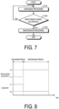
- FIG. 7 is a flowchart illustrating a processing procedure executed by the droplet discharge device according to the embodiment. Each step of processing illustrated in FIG. 7 is executed in accordance with control of the controller 21.
- step S101 discharge processing of discharging droplets of the coloring liquid from the droplet discharge head 300 is performed (step S101).
- the controller 21 controls the displacement element 353 included in the droplet discharge head 300 to apply pressure to the pressurizing chamber 352, and thus the coloring liquid is discharged from the nozzle 351 toward the object 50.
- a cumulative processing period during which the discharge processing is performed is referred to as a "discharge period”.
- the controller 21 controls the discharge pump 202 and the suction pump 203 to start the circulation of the coloring liquid between the tank 201 and the droplet discharge head 300.
- step S102 whether a maintenance period for performing maintenance processing of the droplet discharge head 300 has arrived is determined.
- the determination in step S 102 is made based on, for example, whether the discharge period exceeds a predetermined period. In a case where the maintenance period has not yet arrived (step S102; No), the processing returns to step S101, and the discharge processing is continuously performed.
- step S103 the maintenance processing of the droplet discharge head 300 is performed (step S103).
- the controller 21 controls the circulation mechanism 200 to adjust the circulation flow rate of the coloring liquid circulating between the circulation mechanism 200 and the droplet discharge head 300.
- a mode of adjusting the circulation flow rate of the coloring liquid circulating between the circulation mechanism 200 and the droplet discharge head 300 will be described below.
- the controller 21 finishes the series of processing in the droplet discharge device 1.
- FIG. 8 is an explanatory diagram for describing a mode of adjusting the circulation flow rate according to the embodiment.
- FIG. 8 shows temporal changes of "circulation flow rate” and "viscosity” in the discharge period and the maintenance period.
- the "circulation flow rate” refers to the circulation flow rate of the coloring liquid circulating between the circulation mechanism 200 and the droplet discharge head 300
- the “viscosity” refers to the viscosity of the coloring liquid supplied from the circulation mechanism 200 to the droplet discharge head 300.
- the controller 21 controls the circulation mechanism 200 to increase the circulation flow rate of the coloring liquid to be higher than the circulation flow rate of the coloring liquid in the discharge period.
- the coloring liquid is a pseudoplastic fluid whose viscosity decreases as the shear rate increases.
- the controller 21 can supply the coloring liquid having a viscosity lower than that of the coloring liquid in the discharge period to the droplet discharge head 300.
- the controller 21 changes the channel cross-sectional areas of the first proportional valve 204 and the second proportional valve 205 in the circulation mechanism 200 to change the supply flow rate and the recovery flow rate of the coloring liquid, thereby increasing the circulation flow rate from a circulation flow rate F 1 of the coloring liquid in the discharge period to a circulation flow rate F 2 (> F 1 ).
- the controller 21 can reduce the viscosity of the coloring liquid supplied to the droplet discharge head 300 from a viscosity V 1 of the coloring liquid in the discharge period to a viscosity V 2 ( ⁇ V 1 ).
- the circulation flow rate of the coloring liquid is increased to be higher than the circulation flow rate of the coloring liquid in the discharge period, and thus the viscosity of the coloring liquid can be reduced compared to the viscosity of the coloring liquid in the discharge period.
- the viscosity of the coloring liquid can be reduced such that the residue can be easily peeled off from the inner wall of the channel within the droplet discharge head 300. Consequently, since the residue is smoothly discharged to the outside of the droplet discharge head 300, the residue are less likely to disturb the flow of the coloring liquid in the channel within the droplet discharge head 300. As a result, discharge failure caused by residue remaining in the droplet discharge head 300 can be suppressed.
- the circulation flow rate of the coloring liquid is increased during the entire maintenance period to be higher than the circulation flow rate of the coloring liquid in the discharge period, but the circulation flow rate of the coloring liquid may be increased during a part of the maintenance period.
- the controller 21 may control the circulation mechanism 200 during at least a part of the maintenance period to increase the circulation flow rate of the coloring liquid to be higher than the circulation flow rate of the coloring liquid in the discharge period.
- FIG. 9 is an explanatory diagram for describing a mode of adjusting the circulation flow rate according to Variation 1 of the embodiment.
- the controller 21 controls the circulation mechanism 200 to change the circulation flow rate of the coloring liquid between a first period and a second period subsequent to the first period, which are included in the maintenance period. Accordingly, the controller 21 can change the viscosity of the coloring liquid between the first period and the second period subsequent to the first period, which are included in the maintenance period.
- the controller 21 changes the channel cross-sectional areas of the first proportional valve 204 and the second proportional valve 205 in the circulation mechanism 200 to change the supply flow rate and the recovery flow rate of the coloring liquid, thereby setting the circulation flow rate to the circulation flow rate F 2 in the first period and to a circulation flow rate F 3 ( ⁇ F 2 ) in the second period.
- the controller 21 can set the viscosity of the coloring liquid supplied to the droplet discharge head 300 to the viscosity V 2 in the first period and to a viscosity V 3 (> V 2 ) in the second period.
- the coloring liquid having a relatively low viscosity and the coloring liquid having a relatively high viscosity can be supplied to the droplet discharge head 300.
- the residue can be peeled off from the inner wall of the channel within the droplet discharge head 300 by the coloring liquid having a relatively low viscosity, and the residue remaining in the droplet discharge head 300 can be washed away by the coloring liquid having a relatively high viscosity.
- the circulation flow rate of the coloring liquid is changed from a relatively high flow rate (e.g., the circulation flow rate F 2 ) to a relatively low flow rate (e.g., the circulation flow rate F 3 ).
- the coloring liquid having a relatively low viscosity can be supplied to the droplet discharge head 300.
- the residue is peeled off from the inner wall of the channel within the droplet discharge head 300 by the coloring liquid having a relatively low viscosity, and then the residue remaining in the droplet discharge head 300 can be washed away by the coloring liquid having a relatively high viscosity.
- the residue can be more smoothly discharged to the outside of the droplet discharge head 300.
- FIG. 10 is an explanatory diagram for describing a mode of adjusting the circulation flow rate according to Variation 2 of an embodiment.
- the circulation flow rate of the coloring liquid is changed from a relatively high flow rate to a relatively low flow rate.
- the circulation flow rate of the coloring liquid is changed from a relatively low flow rate to a relatively high flow rate.
- the controller 21 controls the circulation mechanism 200 to set the circulation flow rate to the circulation flow rate F 2 in the first period and to set the circulation flow rate to the circulation flow rate F 3 (> F 2 ) in the second period.
- the controller 21 can set the viscosity of the coloring liquid supplied to the droplet discharge head 300 to the viscosity V 2 in the first period and to the viscosity V 3 ( ⁇ V 2 ) in the second period.
- the circulation flow rate of the coloring liquid is changed from a relatively low flow rate (e.g., the circulation flow rate F 2 ) to a relatively high flow rate (e.g., the circulation flow rate F 3 ).
- the coloring liquid having a relatively high viscosity is supplied to the droplet discharge head 300
- the coloring liquid having a relatively low viscosity can be supplied to the droplet discharge head 300.
- the residue remaining in the droplet discharge head 300 is washed away by the coloring liquid having a relatively high viscosity, and then the residue can be transported at high speed to the downstream side of the channel within the droplet discharge head 300 by the coloring liquid having a relatively low viscosity.
- the residue can be more smoothly discharged to the outside of the droplet discharge head 300.
- the circulation flow rate of the coloring liquid is changed once in the first period and the second period subsequent to the first period, which are included in the maintenance period; however, the disclosed technique is not limited thereto.
- the controller 21 may control the circulation mechanism 200 to perform processing of changing the circulation flow rate of the coloring liquid repeatedly more than once during the maintenance period.
- FIG. 11 is an explanatory diagram for describing a mode of adjusting the circulation flow rate according to Variation 3 of the embodiment.
- Solidified substances of the coloring liquid (hereinafter, appropriately referred to as “solidified substances") remain as residue in the droplet discharge head 300.
- the coloring liquid contains a dissolving component capable of dissolving the solidified substances of the coloring liquid, and the solidified substances remaining in the droplet discharge head 300 are dissolved by the dissolving component.
- the controller 21 controls the circulation mechanism 200 to stop the circulation of the coloring liquid for a predetermined time for allowing the solidified substances remaining in the droplet discharge head 300 to be dissolved in the dissolving component, and to then increase the circulation flow rate of the coloring liquid.
- the controller 21 changes the channel cross-sectional areas of the first proportional valve 204 and the second proportional valve 205 in the circulation mechanism 200 to 0 to stop the circulation of the coloring liquid for a period time, thereby setting the circulation flow rate to 0.
- the controller 21 increases the channel cross-sectional areas of the first proportional valve 204 and the second proportional valve 205 in the circulation mechanism 200 to be larger than 0, thereby increasing the circulation flow rate to the circulation flow rate F 2 that is higher than the circulation flow rate F 1 of the coloring liquid in the discharge period.
- the controller 21 can reduce the viscosity of the coloring liquid supplied to the droplet discharge head 300 to the viscosity V 2 that is lower than the viscosity V 1 of the coloring liquid in the discharge period.
- the circulation of the coloring liquid is stopped for a predetermined time before the circulation flow rate of the coloring liquid is increased.
- the solidified substances remaining in the droplet discharge head 300 can be dissolved in the dissolving component contained in the coloring liquid, and then the solidified substances that have been dissolved can be transported at high speed by the coloring liquid to the downstream side of the channel within the droplet discharge head 300.
- the solidified substances of the coloring liquid can be more smoothly discharged to the outside of the droplet discharge head 300.
- FIG. 12 is an explanatory diagram for describing a mode of adjusting the circulation flow rate according to Variation 4 of the embodiment.
- FIG. 12 shows temporal changes of the "head posture" in the discharge period and the maintenance period.
- the "head posture” refers to the posture of the droplet discharge head 300 mounted on the robotic arm 100.
- the controller 21 controls the circulation mechanism 200 to increase the circulation flow rate of the coloring liquid, and controls the robotic arm 100 to change the posture of the droplet discharge head 300.
- the controller 21 changes the channel cross-sectional areas of the first proportional valve 204 and the second proportional valve 205 in the circulation mechanism 200 to change the supply flow rate and the recovery flow rate of the coloring liquid, thereby increasing the circulation flow rate from the circulation flow rate F 1 of the coloring liquid in the discharge period to the circulation flow rate F 2 (> F 1 ).
- the controller 21 can reduce the viscosity of the coloring liquid supplied to the droplet discharge head 300 from the viscosity V 1 of the coloring liquid during the discharge period to the viscosity V 2 ( ⁇ V 1 ).
- the controller 21 maintains the posture of the droplet discharge head 300 in a constant posture P 1 during the discharge period, and operates the arm portion 110 of the robotic arm 100 during the maintenance period, thereby sequentially changing the posture of the droplet discharge head 300 to a plurality of random postures.
- the posture of the droplet discharge head 300 is changed at the timing when the circulation flow rate of the coloring liquid is increased.
- the timing when the change in posture of the droplet discharge head 300 is started is matched with the timing when the circulation flow rate of the coloring liquid is increased.
- the posture of the droplet discharge head 300 is changed during the entire maintenance period, but the posture of the droplet discharge head 300 may be changed during a part of the maintenance period.
- the controller 21 may control the circulation mechanism 200 to increase the circulation flow rate of the coloring liquid, and may control the robotic arm 100 to change the posture of the droplet discharge head 300.
- FIG. 13 is an explanatory diagram for describing a mode of adjusting the circulation flow rate according to Variation 5 of the embodiment.
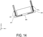
- FIG. 14 is a diagram schematically illustrating an example of the posture of the droplet discharge head according to Variation 5 of the embodiment. Variation 5 relates to a variation of the posture change of the droplet discharge head 300 in Variation 4.
- the controller 21 controls the robotic arm 100 to change the posture of the droplet discharge head 300 to a posture P 2 in which the recovery port 322 is located higher than the supply port 321.
- the examples in FIGs. 13 and 14 are examples in which the posture of the droplet discharge head 300 is changed to the posture in which the recovery port 322 is located higher than the supply port 321.
- the height positions of the supply port 321 and the recovery port 322 may be reversed. That is, the controller 21 may change the posture of the droplet discharge head 300 to a posture in which the supply port 321 is located higher than the recovery port 322. In this case, solidified substances of the coloring liquid remaining in the droplet discharge head 300 can be efficiently moved in the direction of gravitational force.
- FIG. 15 is an explanatory diagram for describing a mode of adjusting the circulation flow rate according to Variation 6 of the embodiment.
- Variation 6 relates to a variation of the posture change of the droplet discharge head 300 in Variation 5.
- the controller 21 changes the posture of the droplet discharge head 300 between the posture P 2 in which the recovery port 322 is located higher than the supply port 321 and a posture P 3 in which the supply port 321 is located higher than the recovery port 322.
- the posture of the droplet discharge head 300 is changed between the posture in which the recovery port 322 is located relatively high and the posture in which the supply port 321 is located relatively high, the movement of the solidified substances and air bubbles of the coloring liquid between the supply port 321 and the recovery port 322 can be promoted.
- the solidified substances and air bubbles of the coloring liquid can be smoothly discharged from the recovery port 322 to the outside of the droplet discharge head 300.
- FIG. 16 is an explanatory diagram for describing a mode of adjusting the circulation flow rate according to Variation 7 of the embodiment.
- FIG. 16 shows temporal change of "applied pressure" in the discharge period and the maintenance period.
- the term “applied pressure” refers to pressure applied from the displacement element 353 to the pressurizing chamber 352 in the droplet discharge head 300.
- the controller 21 controls the circulation mechanism 200 to cause the displacement element 353 to apply pressure to the pressurizing chamber 352 while increasing the circulation flow rate of the coloring liquid.
- the controller 21 applies a pressure C 1 to the pressurizing chamber 352 by the displacement element 353 during the discharge period and maintains the application of the pressure from the displacement element 353 to the pressurizing chamber 352 while increasing the circulation flow rate to the circulation flow rate F 2 (> F 1 ) during the maintenance period.
- the controller 21 can reduce the viscosity of the coloring liquid supplied to the droplet discharge head 300 from the viscosity V 1 of the coloring liquid in the discharge period to the viscosity V 2 ( ⁇ V 1 ).
- pressure is applied to the pressurizing chamber 352 while increasing the circulation flow rate of the coloring liquid, and thus a pressure wave can be generated in the pressurizing chamber 352 while reducing the viscosity of the coloring liquid supplied to the droplet discharge head 300.
- FIG 17 is a diagram illustrating propagation of the pressure wave according to Variation 7 of the embodiment.
- the pressure wave PW generated in the pressurizing chamber 352 is propagated to the manifolds, and thus residue remaining in the manifolds can be concentratively removed by the pressure wave PW.
- the example in FIG. 16 is an example in which the pressure applied to the pressurizing chamber 352 during the discharge period and the pressure applied to the pressurizing chamber 352 during the maintenance period are both the pressure C 1 .
- the pressure applied to the pressurizing chamber 352 during the maintenance period may be lower than the pressure applied to the pressurizing chamber 352 during the discharge period (i.e., the pressure for discharging the coloring liquid from the nozzle 351).
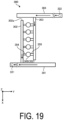
- FIGs. 18 and 19 are explanatory diagrams for describing an internal configuration of the droplet discharge head 300 according to Variation 8 of the embodiment and the mode of circulating the coloring liquid.
- a channel resistance of the separate recovery channel 355 connecting the pressurizing chamber 352 and the recovery manifold 303 of the discharge unit 305 is smaller than a channel resistance of the separate supply channel 354 connecting the pressurizing chamber 352 and the supply manifold 302.
- the channel width of the separate recovery channel 355 is set to be larger than the channel width of the separate supply channel 354, and thus the channel resistance of the separate recovery channel 355 can be made smaller than the channel resistance of the separate supply channel 354.
- the controller 21 controls the circulation mechanism 200 to circulate the coloring liquid from the recovery port 322 toward the supply port 321.
- the controller 21 controls the circulation mechanism 200 to circulate the coloring liquid from the supply port 321 toward the recovery port 322.
- the controller 21 controls the circulation mechanism 200 to reverse the flow direction of the coloring liquid and circulate the coloring liquid from the recovery port 322 toward the supply port 321.
- the circulation direction (flow direction) of the coloring liquid is changed from the direction from the supply port 321 toward the recovery port 322 to the direction from the recovery port 322 toward the supply port 321. Accordingly, in Variation 8, the coloring liquid flows through the recovery reservoir 304, the recovery manifold 303, the separate recovery channel 355, the discharge unit 305, the separate supply channel 354, the supply manifold 302, and the supply reservoir 301 in this order.
- the channel resistance of the separate recovery channel 355 is smaller than the channel resistance of the separate supply channel 354.
- the shear rate of the coloring liquid increases and the viscosity of the coloring liquid decreases in the separate recovery channel 355, and the coloring liquid having the decreased viscosity flows via the discharge unit 305 and the separate supply channel 354 into the supply manifold 302 and reaches a tip portion 302a of the supply manifold 302.
- the coloring liquid remaining in the tip portion 302a of the supply manifold 302 and having a relatively high viscosity can be replaced with the coloring liquid having a relatively low viscosity.
- the circulation mechanism 200 supplies the coloring liquid to the droplet discharge head 300 .
- the supply unit that supplies the coloring liquid to the droplet discharge head 300 is not limited to the circulation mechanism 200.
- the supply unit may be a liquid supply mechanism including a plurality of liquid supply sources that respectively supply a plurality of coloring liquids having different viscosities, supply channels that connect the plurality of liquid supply sources to the droplet discharge head 300, and on-off valves respectively disposed in the supply channels for the liquid supply sources.
- the controller 21 may control the on-off valves of the liquid supply mechanism during at least a part of the maintenance period after the discharge period to supply the coloring liquid having a viscosity lower than that of the coloring liquid in the discharge period to the droplet discharge head 300.
- the coloring liquid may not be a pseudoplastic fluid.
- the droplet discharge head 300 may include at least the nozzle 351, the pressurizing chamber 352 connected to the nozzle 351, and an actuator (the displacement element 353) that applies pressure to the pressurizing chamber 352.
- the droplet discharge device (e.g., the droplet discharge device 1) according to the embodiment includes a droplet discharge head (e.g., the droplet discharge head 300), a supply unit (e.g., the circulation mechanism 200), and a controller (e.g., the controller 21).
- the droplet discharge head discharges droplets of the coloring liquid.
- the supply unit supplies the coloring liquid to the droplet discharge head.
- the controller controls each unit. During at least a part of the maintenance period after the discharge period in which droplets of the coloring liquid are discharged from the droplet discharge head, the controller controls the supply unit to supply the coloring liquid having a viscosity lower than that of the coloring liquid in the discharge period to the droplet discharge head.
- the droplet discharge device according to the embodiment can suppress discharge failure caused by residue in the droplet discharge head.
- the coloring liquid may be a pseudoplastic fluid whose viscosity decreases as the shear rate increases.
- the supply unit may be a circulation mechanism (e.g., the circulation mechanism 200) that supplies the coloring liquid to the droplet discharge head while controlling the circulation flow rate of the coloring liquid circulating between the supply unit and the droplet discharge head.
- the controller may control the circulation mechanism to increase the circulation flow rate of the coloring liquid to be higher than the circulation flow rate of the coloring liquid in the discharge period.
- the circulation flow rate of the coloring liquid is increased to be higher than the circulation flow rate of the coloring liquid in the discharge period, and thus the viscosity of the coloring liquid can be reduced compared to the viscosity of the coloring liquid in the discharge period.
- the droplet discharge device according to the embodiment can easily peel off residue from the inner wall of the channel within the droplet discharge head.
- the controller may control the circulation mechanism to change the circulation flow rate of the coloring liquid between the first period and the second period subsequent to the first period, which are included in the maintenance period.
- the circulation flow rate of the coloring liquid changed as described, the coloring liquid having a relatively low viscosity and the coloring liquid having a relatively high viscosity can be supplied to the droplet discharge head.
- residue can be peeled off from the inner wall of the channel within the droplet discharge head by the coloring liquid having a relatively low viscosity, and residue remaining in the droplet discharge head can be washed away by the coloring liquid having a relatively high viscosity.
- the controller may control the circulation mechanism to set the circulation flow rate of the coloring liquid to the first flow rate in the first period and to the second flow rate lower than the first flow rate in the second period.
- the controller may control the circulation mechanism to set the circulation flow rate of the coloring liquid to a first flow rate in the first period and to a second flow rate higher than the first flow rate in the second period.
- the controller may control the circulation mechanism to stop the circulation of the coloring liquid for a predetermined time and then increase the circulation flow rate of the coloring liquid.
- the coloring liquid contains a dissolving component capable of dissolving the solidified substances of the coloring liquid
- the droplet discharge device enables the solidified substances remaining in the droplet discharge head to be dissolved in the dissolving component contained in the coloring liquid, and the solidified substances that have been dissolved can be transported at a high speed by the coloring liquid to the downstream side of the channel within the droplet discharge head.
- the predetermined time may be, for example, a time required for the solidified substances remaining in the droplet discharge head to be dissolved in the dissolving component, but may be shorter or longer than that time.
- the droplet discharge device may further include a robotic arm (e.g., the robotic arm 100).
- the robotic arm is provided with the droplet discharge head such that the posture of the droplet discharge head is changeable.
- the controller may control the circulation mechanism to increase the circulation flow rate of the coloring liquid, and may control the robotic arm to change the posture of the droplet discharge head.
- the droplet discharge device can promote the movement of residue in the direction of gravitational force and in the direction opposite to the direction of gravitational force, and thus the residue can be smoothly discharged to the outside of the droplet discharge head.
- the controller may change the posture of the droplet discharge head at the timing when the circulation flow rate of the coloring liquid is increased.
- the droplet discharge device can further promote the movement of residue in the direction of gravitational force and in the direction opposite to the direction of gravitational force, and thus the residue can be more smoothly discharged to the outside of the droplet discharge head.
- the droplet discharge head may include a supply port (e.g., the supply port 321) for supplying the coloring liquid to the inside of the droplet discharge head and a recovery port (e.g., the recovery port 322) for recovering the coloring liquid from the inside of the droplet discharge head.
- the controller may change the posture of the droplet discharge head to a posture in which one of the supply port and the recovery port is located higher than the other. As a result, the droplet discharge device according to the embodiment can smoothly discharge the solidified substances or air bubbles of the coloring liquid from the recovery port to the outside of the droplet discharge head.
- the controller may change the posture of the droplet discharge head between a posture in which one of the supply port and the recovery port is located higher than the other and a posture in which the other of the supply port and the recovery port is located higher than the one.
- the droplet discharge head may include a discharge unit (e.g., the discharge unit 305), a supply manifold (e.g., the supply manifold 302), and a recovery manifold (e.g., the recovery manifold 303).
- the discharge unit may include a nozzle (e.g., the nozzle 351), a pressurizing chamber (e.g., the pressurizing chamber 352), and a pressurizing unit (e.g., the displacement element 353).
- the pressurizing chamber is connected to the nozzle.
- the pressurizing unit applies pressure to the pressurizing chamber to discharge droplets of the coloring liquid from the nozzle.
- the supply manifold is connected to the pressurizing chamber and is configured to supply the coloring liquid to the pressurizing chamber.
- the recovery manifold is connected to the pressurizing chamber and is configured to recover the coloring liquid from the pressurizing chamber.
- the controller may control the circulation mechanism to cause the pressurizing unit to apply pressure to the pressurizing chamber while increasing the circulation flow rate of the coloring liquid. Accordingly, the difference between the viscosity of the coloring liquid flowing through the pressurizing chamber and the viscosity of the coloring liquid flowing through the manifold connected to the pressurizing chamber can be reduced, and thus a pressure wave generated in the pressurizing chamber is easily transmitted not only to the pressurizing chamber but also to the manifold. As a result, the droplet discharge device according to the embodiment can concentratively remove the residue remaining in the manifold by the pressure wave.
- the droplet discharge head may include a discharge unit (e.g., the discharge unit 305), a supply manifold (e.g., the supply manifold 302), and a recovery manifold (e.g., the recovery manifold 303).
- the discharge unit may include a nozzle (e.g., the nozzle 351), a pressurizing chamber (e.g., the pressurizing chamber 352), and a pressurizing unit (e.g., the displacement element 353).
- the pressurizing chamber is connected to the nozzle.
- the pressurizing unit applies pressure to the pressurizing chamber to discharge droplets of the coloring liquid from the nozzle.
- the supply manifold is connected to the pressurizing chamber and is configured to supply the coloring liquid supplied from a supply port (e.g., the supply port 321) side of the droplet discharge head, to the pressurizing chamber.
- the recovery manifold is connected to the pressurizing chamber and is configured to recover the coloring liquid from the pressurizing chamber and send out the coloring liquid to a recovery port (e.g., the recovery port 322) side of the droplet discharge head.
- the pressurizing chamber and the supply manifold may be connected to each other via a separate supply channel (e.g., the separate supply channel 354).
- the pressurizing chamber and the recovery manifold may be connected to each other via a separate recovery channel (e.g., the separate recovery channel 355).
- the channel resistance of the separate recovery channel may be smaller than the channel resistance of the separate supply channel.
- the controller may control the circulation mechanism to circulate the coloring liquid from the recovery port toward the supply port.
- the droplet discharge device can replace the coloring liquid having relatively high viscosity and remaining in a tip portion (e.g., the tip portion 302a) of the supply manifold with the coloring liquid having relatively low viscosity.
Landscapes
- Chemical & Material Sciences (AREA)
- Analytical Chemistry (AREA)
- Physics & Mathematics (AREA)
- Fluid Mechanics (AREA)
- Engineering & Computer Science (AREA)
- Robotics (AREA)
- Ink Jet (AREA)
- Coating Apparatus (AREA)
Abstract
Description
- The disclosed embodiments relate to a droplet discharge device and a maintenance method.
- Inkjet printers and inkjet plotters utilizing an inkjet recording method are known examples of printing apparatuses. A droplet discharge head for discharging liquid is installed in such printing apparatuses utilizing an inkjet method.
- Also, in printing apparatuses utilizing an inkjet method, a technique has been proposed in which a cleaning liquid is supplied to a droplet discharge head to stop the droplet discharge head from clogging.
- Patent Document 1:
JP 3629926 B - A droplet discharge device according to one aspect of an embodiment includes a droplet discharge head, a supply unit, and a controller. The droplet discharge head discharges droplets of a coloring liquid. The supply unit supplies the coloring liquid to the droplet discharge head. The controller controls each unit. During at least a part of a maintenance period after a discharge period in which droplets of the coloring liquid are discharged from the droplet discharge head, the controller controls the supply unit to supply the coloring liquid having a viscosity lower than that of the coloring liquid in the discharge period to the droplet discharge head.
-
-
FIG. 1 is a diagram schematically illustrating a configuration example of a droplet discharge device according to an embodiment. -
FIG. 2 is a perspective view schematically illustrating an outer appearance configuration of a droplet discharge head according to the embodiment. -
FIG. 3 is a plan view illustrating the droplet discharge head according to the embodiment. -
FIG. 4 is a diagram schematically illustrating channels inside the droplet discharge head according to the embodiment. -
FIG. 5 is a diagram schematically illustrating a configuration example of a discharge unit according to the embodiment. -
FIG. 6 is a diagram schematically illustrating a circulation mechanism according to the embodiment. -
FIG. 7 is a flowchart illustrating a processing procedure executed by the droplet discharge device according to the embodiment. -
FIG. 8 is an explanatory diagram for describing a mode of adjusting the circulation flow rate according to the embodiment. -
FIG. 9 is an explanatory diagram for describing a mode of adjusting the circulation flow rate according toVariation 1 of the embodiment. -
FIG. 10 is an explanatory diagram for describing a mode of adjusting the circulation flow rate according toVariation 2 of the embodiment. -
FIG. 11 is an explanatory diagram for describing a mode of adjusting the circulation flow rate according toVariation 3 of the embodiment. -
FIG. 12 is an explanatory diagram for describing a mode of adjusting the circulation flow rate according to Variation 4 of the embodiment. -
FIG. 13 is an explanatory diagram for describing a mode of adjusting the circulation flow rate according to Variation 5 of the embodiment. -
FIG. 14 is a diagram schematically illustrating an example of a posture of the droplet discharge head according to Variation 5 of the embodiment. -
FIG. 15 is an explanatory diagram for describing a mode of adjusting the circulation flow rate according to Variation 6 of the embodiment. -
FIG. 16 is an explanatory diagram for describing a mode of adjusting the circulation flow rate according to Variation 7 of the embodiment. -
FIG. 17 is a diagram illustrating propagation of a pressure wave according to Variation 7 of the embodiment. -
FIG. 18 is an explanatory diagram for describing an internal configuration of the droplet discharge head according to Variation 8 of the embodiment and a mode of circulating a coloring liquid. -
FIG. 19 is an explanatory diagram for describing the internal configuration of the droplet discharge head according to Variation 8 of the embodiment and the mode of circulating the coloring liquid. - Hereinafter, embodiments of a droplet discharge device and a maintenance method that are disclosed in the present application will be described with reference to the accompanying drawings. The present disclosure is not limited by the following embodiments. Note that the drawings are schematic and that the dimensional relationships between elements, the proportions of the elements, and the like may differ from the actual ones. There may be differences between the drawings in terms of dimensional relationships, proportions, and the like.
- In the embodiments described below, expressions such as "constant", "orthogonal", "perpendicular", and "parallel" may be used, but these expressions do not mean exactly "constant", "orthogonal", "perpendicular", and "parallel". In other words, it is assumed that the above expressions allow for deviations in manufacturing accuracy, installation accuracy, or the like.
- Embodiments can be appropriately combined so as not to contradict each other in terms of processing content. In the following embodiments, the same portions are denoted by the same reference signs, and redundant explanations are omitted.
- The droplet discharge device disclosed in the present application can be applied to inkjet printers and inkjet plotters that utilize an inkjet recording method, as well as devices that discharge droplets using an inkjet method.
- Example of Outer Appearance Configuration of Droplet Discharge Device A configuration of a droplet discharge device according to an embodiment will be described with reference to
FIG. 1. FIG. 1 is a diagram schematically illustrating a configuration example of the droplet discharge device according to the embodiment. - As illustrated in
FIG. 1 , adroplet discharge device 1 includes arobotic arm 100, acirculation mechanism 200, adroplet discharge head 300, and acontrol device 2. - The
robotic arm 100 is assembled on abase 10 mounted on, for example, a horizontal floor surface indoors or outdoors. Therobotic arm 100 includes anarm portion 110. Thearm portion 110 is made up of a plurality of parts that are bent and stretched and rotatably assembled. In response to a command from acontroller 21 described below, thearm portion 110 can, for example, move thedroplet discharge head 300 mounted on a tip of thearm portion 110 and change the position, posture, and angle of thedroplet discharge head 300. Thearm portion 110 illustrated inFIG. 1 is not particularly limited to the configuration illustrated inFIG. 1 as long as thearm portion 110 is provided with a degree of freedom with which thedroplet discharge head 300 can change the movement, position, posture, angle, and the like as necessary. - The
robotic arm 100 can be moved in a vertical direction (Z axis direction) by thearm portion 110, which, for example, moves thecirculation mechanism 200 and thedroplet discharge head 300 that are mounted on the tip of thearm portion 110 along a predetermined axis of rotation. This allows thecirculation mechanism 200 and thedroplet discharge head 300 to, for example, assume a posture in which, as illustrated inFIG. 1 , a liquid discharge surface 30SF of thedroplet discharge head 300 faces parallel to a spraying surface 50SF of anobject 50. Therobotic arm 100 can, by thearm portion 110, rotate thecirculation mechanism 200 and thedroplet discharge head 300 that are assembled on the tip of thearm portion 110 about a predetermined axis of rotation, for example. This allows thecirculation mechanism 200 and thedroplet discharge head 300 to, for example, switch position in a longitudinal direction and in a lateral direction, or to invert an upper position and a lower position. - The
circulation mechanism 200 is installed at a tip portion of thearm portion 110 of therobotic arm 100. Thecirculation mechanism 200 supplies a coloring liquid to thedroplet discharge head 300 while controlling the circulation flow rate of the coloring liquid circulating between thecirculation mechanism 200 and thedroplet discharge head 300. Thecirculation mechanism 200 functions as a supply unit that supplies the coloring liquid to thedroplet discharge head 300. - The
droplet discharge head 300 is assembled on thecirculation mechanism 200 installed at the tip portion of thearm portion 110 of therobotic arm 100. Thedroplet discharge head 300 functions as a droplet discharge unit that discharges droplets of the coloring liquid to theobject 50. The coloring liquid is liquid that can be applied to theobject 50 to color theobject 50. A case in which the coloring liquid is a pseudoplastic fluid whose viscosity decreases as the shear rate increases is described as an example, but the coloring liquid may not be a pseudoplastic fluid. For example, ink, paint, or the like can be used as the coloring liquid. - The
control device 2 is, for example, a computer, and includes thecontroller 21 such as a processor and a storage 22 such as a memory. A control program for controlling a variety of processing to be executed in thedroplet discharge device 1 is stored in the storage 22. Thecontroller 21 reads out the program stored in the storage 22 and executes the program, thereby controlling the operation of thedroplet discharge device 1. - The program may be recorded in a computer-readable storage medium and installed in the storage 22 of the
control device 2 from the storage medium. Examples of the computer-readable storage medium include a hard disk (HD), a flexible disk (FD), a compact disk (CD), a magneto-optical disk (MO), and a memory card. - Incidentally, after droplets of the coloring liquid are discharged, various residue may remain in the
droplet discharge head 300. Examples of the residue include solidified substances of the coloring liquid and air bubbles. When the residue remains in thedroplet discharge head 300, the flow of the coloring liquid is disturbed, and thus discharge failure of thedroplet discharge head 300 may occur. In view of this point, the present application proposes thedroplet discharge device 1 that can reduce the likelihood of discharge failure caused by residue remaining in thedroplet discharge head 300. - The
droplet discharge head 300 according to the embodiment will be described with reference toFIGS. 2 to 4 .FIG. 2 is a perspective view schematically illustrating an outer appearance configuration of the droplet discharge head according to the embodiment.FIG. 3 is a plan view of the droplet discharge head according to the embodiment.FIG. 4 is a diagram schematically illustrating channels inside the droplet discharge head according to the embodiment. - As illustrated in
FIG. 2 , thedroplet discharge head 300 includes a housing including a box-shapedmember 310 and a substantially plate-shapedmember 320. The housing of thedroplet discharge head 300 is provided with asupply port 321 for supplying the coloring liquid to the inside of thedroplet discharge head 300 and arecovery port 322 for recovering the coloring liquid from the inside of thedroplet discharge head 300. A first channel RT1 for supplying the coloring liquid from thecirculation mechanism 200 to the inside of the head is connected to thesupply port 321. A second channel RT2 for sending the coloring liquid recovered within the head back to thecirculation mechanism 200 is connected to therecovery port 322. - As illustrated in
FIG. 3 , thedroplet discharge head 300 includes asupply reservoir 301, asupply manifold 302, arecovery manifold 303, arecovery reservoir 304, and adischarge unit 305. - The
supply reservoir 301 has an elongated shape extending in a longitudinal direction (Y axis direction) of thedroplet discharge head 300 and connects to thesupply manifold 302. Thesupply reservoir 301 includes a channel therein. As illustrated inFIG. 4 , the coloring liquid supplied through the first channel RT1 and thesupply port 321 to thesupply reservoir 301 and stored in the channel of thesupply reservoir 301 is delivered to thesupply manifold 302. - The
supply manifold 302 has an elongated shape extending in a lateral direction (X axis direction) of thedroplet discharge head 300 to a position before therecovery reservoir 304. Thesupply manifold 302 includes a channel therein in communication with the channel included in thesupply reservoir 301 and with thedischarge unit 305. As illustrated inFIG. 4 , the coloring liquid delivered from thesupply reservoir 301 to thesupply manifold 302 is fed from thesupply manifold 302 to thedischarge unit 305. - The
recovery manifold 303 has an elongated shape extending in the lateral direction (X axis direction) of thedroplet discharge head 300 to a position before thesupply reservoir 301. Therecovery manifold 303 has a channel therein in communication with the channel included in therecovery reservoir 304 and with thedischarge unit 305. As illustrated inFIG. 4 , the coloring liquid that has not been discharged from thedischarge unit 305 to the outside is fed into therecovery manifold 303. - The
recovery reservoir 304 has an elongated shape extending in the longitudinal direction (Y axis direction) of thedroplet discharge head 300 and is connected to therecovery manifold 303. Therecovery reservoir 304 includes a channel therein. As illustrated inFIG. 4 , the coloring liquid fed from therecovery manifold 303 to therecovery reservoir 304 and stored in the channel of therecovery reservoir 304 is fed back through therecovery port 322 and the second channel RT2 to a tank 201 (seeFIG. 6 ). -
FIG. 5 is a diagram schematically illustrating a configuration example of the discharge unit according to the embodiment. As illustrated inFIG. 5 , thedischarge unit 305 includes anozzle 351, a pressurizingchamber 352, and adisplacement element 353. Thenozzle 351 is a discharge hole that is open to the discharge surface 30SF (seeFIG. 1 ) of thedroplet discharge head 300. - The pressurizing
chamber 352 is connected to thenozzle 351. The pressurizingchamber 352 includes abody portion 361 to which pressure is applied by thedisplacement element 353, and adescender 362 serving as a channel connecting thebody portion 361 and thenozzle 351. The pressurizingchamber 352 and thesupply manifold 302 are connected to each other via aseparate supply channel 354. The coloring liquid delivered from thesupply manifold 302 to thedischarge unit 305 is supplied through theseparate supply channel 354 to the pressurizingchamber 352. The pressurizingchamber 352 and therecovery manifold 303 are connected to each other via aseparate recovery channel 355. The coloring liquid that has not been discharged from thenozzle 351 to the outside is recovered from the pressurizingchamber 352 to therecovery manifold 303. - The
displacement element 353 is located on a surface of thebody portion 361 of the pressurizingchamber 352 on a side opposite to thedescender 362. Thedisplacement element 353 is an element that deforms in response to a predetermined driving signal. Thedisplacement element 353 functions as a pressurizing unit that applies pressure to the pressurizingchamber 352 to discharge droplets of the coloring liquid from thenozzle 351. That is, when thedisplacement element 353 is deformed, pressure (positive pressure and negative pressure) is applied to the pressurizingchamber 352, and droplets of the coloring liquid are discharged from thenozzle 351. Thedisplacement element 353 is electrically connected to thecontrol device 2 and is controlled by thecontrol device 2. - The
discharge unit 305 having such a configuration sucks out the coloring liquid from thesupply manifold 302 by the negative pressure applied to the pressurizingchamber 352, and discharges the sucked coloring liquid from thenozzle 351 toward theobject 50 by the positive pressure applied to the pressurizingchamber 352. - Next, a configuration example of the
circulation mechanism 200 according to the embodiment will be described.FIG. 6 is a diagram schematically illustrating the circulation mechanism according to the embodiment. - As illustrated in
FIG. 6 , thecirculation mechanism 200 includes atank 201, adischarge pump 202, asuction pump 203, a firstproportional valve 204, a secondproportional valve 205, and aheater 206. Thecirculation mechanism 200 also includes afirst pressure sensor 208, asecond pressure sensor 209, athird pressure sensor 210, afourth pressure sensor 211, and a flowmeter 212. - The
circulation mechanism 200 also includes the first channel RT1 and the second channel RT2. The first channel RT1 is a channel that connects thetank 201 and thedroplet discharge head 300 to cause the coloring liquid stored in thetank 201 to flow into thedroplet discharge head 300. The second channel RT2 is a channel that connects thetank 201 and thedroplet discharge head 300 to cause the coloring liquid that has flowed into thedroplet discharge head 300 to return to thetank 201. The coloring liquid recovered within thedroplet discharge head 300 without being discharged from thedroplet discharge head 300 to the outside is sent back through the second channel RT2 to thetank 201. The first channel RT1 and the second channel RT2 can be implemented, for example, by a pipe made of a predetermined material that does not interact with constituents of the coloring liquid. As illustrated inFIG. 6 , for example, thecirculation mechanism 200 having such components controls the circulation flow rate of the coloring liquid circulating clockwise between thetank 201 and thedroplet discharge head 300 in accordance with control by thecontroller 21. - The
tank 201 stores the coloring liquid supplied to thedroplet discharge head 300. Thetank 201 functions as a storage for storing the coloring liquid supplied to thedroplet discharge head 300. - The
discharge pump 202 feeds the coloring liquid stored in thetank 201 to thedroplet discharge head 300 through the first channel RT1. Thedischarge pump 202 generates positive pressure for feeding the coloring liquid stored in thetank 201 to thedroplet discharge head 300. Thedischarge pump 202 can, for example, feed the coloring liquid stored in thetank 201 to thedroplet discharge head 300 at a predetermined constant supply pressure. - The
suction pump 203 feeds the coloring liquid recovered in thedroplet discharge head 300 to thetank 201 through the second channel RT2. Thesuction pump 203 sucks the coloring liquid recovered in thedroplet discharge head 300 to generate negative pressure for sending the coloring liquid back to thetank 201. Thesuction pump 203 can, for example, feed the coloring liquid sucked from thedroplet discharge head 300 to thetank 201 at a predetermined constant recovery pressure. - The
discharge pump 202 and thesuction pump 203 can be implemented by a rotary pump such as a gear pump or a displacement pump such as a diaphragm pump. - The first
proportional valve 204 is interposed in the first channel RT1 between thetank 201 and thedroplet discharge head 300 to proportionally control the flow rate of the coloring liquid supplied to thedroplet discharge head 300. The firstproportional valve 204 can continuously modify the channel cross-sectional area for the coloring liquid between 0 to 100%, and controls the flow rate of the coloring liquid to a desired flow rate. For example, the firstproportional valve 204 can reduce the supply flow rate when supplying the coloring liquid to thedroplet discharge head 300 by reducing the channel cross-sectional area for the coloring liquid. On the other hand, the firstproportional valve 204 can increase the supply flow rate when supplying the liquid to thedroplet discharge head 300 by increasing the channel cross-sectional area for the liquid. - The second
proportional valve 205 is interposed in the second channel RT2 between thetank 201 and thedroplet discharge head 300 to proportionally control the flow rate of the coloring liquid fed from thedroplet discharge head 300 to thetank 201. As with the firstproportional valve 204, the secondproportional valve 205 can continuously modify the channel cross-sectional area for the liquid between 0 to 100%, and controls the flow rate of the coloring liquid to a desired flow rate. For example, the secondproportional valve 205 can reduce the recovery flow rate when recovering the coloring liquid from thedroplet discharge head 300 by reducing the channel cross-sectional area for the coloring liquid. On the other hand, the secondproportional valve 205 can increase the recovery flow rate when recovering the coloring liquid from thedroplet discharge head 300 by increasing the channel cross-sectional area for the coloring liquid. - The first
proportional valve 204 and the secondproportional valve 205 can be implemented by a proportional selector valve of an electromagnetic type or a proportional selector valve of a pneumatic type. - The
heater 206 is provided in the first channel RT1 or adjacent to the first channel RT1, and heats the coloring liquid flowing through the first channel RT1. - The
first pressure sensor 208 measures the pressure of the coloring liquid fed by thedischarge pump 202 from thetank 201 to thedroplet discharge head 300. Thefirst pressure sensor 208 measures the pressure downstream of thedischarge pump 202 in a circulation direction of the coloring liquid in thecirculation mechanism 200. Thefirst pressure sensor 208 sends the measurement results to thecontroller 21. - The
second pressure sensor 209 measures the pressure of the coloring liquid that is sucked from thedroplet discharge head 300 by thesuction pump 203 and fed to thetank 201. Thesecond pressure sensor 209 measures the pressure upstream of thesuction pump 203 in the circulation direction of the coloring liquid in thecirculation mechanism 200. Thesecond pressure sensor 209 sends the measurement results to thecontroller 21. - The
third pressure sensor 210 functions as a first pressure measuring unit that measures the pressure of the coloring liquid flowing between the firstproportional valve 204 and thedroplet discharge head 300 through the first channel RT1 as the supply pressure. Thethird pressure sensor 210 sends the measurement results to thecontroller 21. - The
fourth pressure sensor 211 functions as a second pressure measuring unit that measures the pressure of the coloring liquid flowing between the secondproportional valve 205 and thedroplet discharge head 300 through the second channel RT2 as the recovery pressure. Thefourth pressure sensor 211 sends the measurement results to thecontroller 21. - The flowmeter 212 measures the flow rate of the coloring liquid fed to the
droplet discharge head 300. The flowmeter 212 sends the measurement results to thecontroller 21. - The
controller 21 makes an adjustment to keep constant the positive pressure applied to the coloring liquid that thedischarge pump 202 feeds, in accordance with the measurement result of thefirst pressure sensor 208 and the measurement result of thethird pressure sensor 210. For example, thecontroller 21 adjusts the positive pressure of thedischarge pump 202 such that the pressure of the coloring liquid obtained from the measurement result of the measurement result of thefirst pressure sensor 208 remains approximately 1.2 to 3 times larger than the pressure of the coloring liquid obtained from the measurement result of thethird pressure sensor 210. - The
controller 21 also makes an adjustment to keep constant the negative pressure applied to the coloring liquid that thesuction pump 203 sucks, in accordance with the measurement result of thesecond pressure sensor 209 and thefourth pressure sensor 211. For example, thecontroller 21 adjusts the negative pressure of thesuction pump 203 such that the pressure of the coloring liquid obtained from the measurement result of the measurement result of thesecond pressure sensor 209 remains approximately 1.2 to 3 times lower than the pressure of the coloring liquid obtained from the measurement result of thefourth pressure sensor 211. - The
controller 21 circulates the coloring liquid between thetank 201 and thedroplet discharge head 300 by adjusting and keeping constant the differential pressure between the positive pressure that thedischarge pump 202 applies to the coloring liquid and the negative pressure that thesuction pump 203 applies to the coloring liquid. - Next, a specific operation of the droplet discharge device according to the embodiment will be described with reference to
FIG. 7. FIG. 7 is a flowchart illustrating a processing procedure executed by the droplet discharge device according to the embodiment. Each step of processing illustrated inFIG. 7 is executed in accordance with control of thecontroller 21. - As illustrated in
FIG. 7 , in thedroplet discharge device 1, first, discharge processing of discharging droplets of the coloring liquid from thedroplet discharge head 300 is performed (step S101). In the discharge processing, thecontroller 21 controls thedisplacement element 353 included in thedroplet discharge head 300 to apply pressure to the pressurizingchamber 352, and thus the coloring liquid is discharged from thenozzle 351 toward theobject 50. Hereinafter, a cumulative processing period during which the discharge processing is performed is referred to as a "discharge period". - Before starting the discharge processing, the
controller 21 controls thedischarge pump 202 and thesuction pump 203 to start the circulation of the coloring liquid between thetank 201 and thedroplet discharge head 300. - Subsequently, in the
droplet discharge device 1, whether a maintenance period for performing maintenance processing of thedroplet discharge head 300 has arrived is determined (step S102). The determination instep S 102 is made based on, for example, whether the discharge period exceeds a predetermined period. In a case where the maintenance period has not yet arrived (step S102; No), the processing returns to step S101, and the discharge processing is continuously performed. - On the other hand, in a case where the maintenance period has arrived (step S102; Yes), the maintenance processing of the
droplet discharge head 300 is performed (step S103). In the maintenance processing, thecontroller 21 controls thecirculation mechanism 200 to adjust the circulation flow rate of the coloring liquid circulating between thecirculation mechanism 200 and thedroplet discharge head 300. A mode of adjusting the circulation flow rate of the coloring liquid circulating between thecirculation mechanism 200 and thedroplet discharge head 300 will be described below. When the maintenance processing is finished, thecontroller 21 finishes the series of processing in thedroplet discharge device 1. - Hereinafter, a mode of adjusting the circulation flow rate of the coloring liquid circulating between the
circulation mechanism 200 and thedroplet discharge head 300 will be described with reference toFIG. 8. FIG. 8 is an explanatory diagram for describing a mode of adjusting the circulation flow rate according to the embodiment. -
FIG. 8 shows temporal changes of "circulation flow rate" and "viscosity" in the discharge period and the maintenance period. The "circulation flow rate" refers to the circulation flow rate of the coloring liquid circulating between thecirculation mechanism 200 and thedroplet discharge head 300, and the "viscosity" refers to the viscosity of the coloring liquid supplied from thecirculation mechanism 200 to thedroplet discharge head 300. - As shown in
FIG. 8 , during the maintenance period after the discharge period, thecontroller 21 controls thecirculation mechanism 200 to increase the circulation flow rate of the coloring liquid to be higher than the circulation flow rate of the coloring liquid in the discharge period. Here, as described above, the coloring liquid is a pseudoplastic fluid whose viscosity decreases as the shear rate increases. As the circulation flow rate of the coloring liquid increases, the shear rate of the coloring liquid with respect to the circulation direction increases and the viscosity of the coloring liquid decreases. Accordingly, by increasing the circulation flow rate of the coloring liquid during the maintenance period, thecontroller 21 can supply the coloring liquid having a viscosity lower than that of the coloring liquid in the discharge period to thedroplet discharge head 300. - For example, the
controller 21 changes the channel cross-sectional areas of the firstproportional valve 204 and the secondproportional valve 205 in thecirculation mechanism 200 to change the supply flow rate and the recovery flow rate of the coloring liquid, thereby increasing the circulation flow rate from a circulation flow rate F1 of the coloring liquid in the discharge period to a circulation flow rate F2 (> F1). Thus, during the maintenance period, thecontroller 21 can reduce the viscosity of the coloring liquid supplied to thedroplet discharge head 300 from a viscosity V1 of the coloring liquid in the discharge period to a viscosity V2 (< V1). - As described above, during the maintenance period after the discharge period, the circulation flow rate of the coloring liquid is increased to be higher than the circulation flow rate of the coloring liquid in the discharge period, and thus the viscosity of the coloring liquid can be reduced compared to the viscosity of the coloring liquid in the discharge period.
- With the
droplet discharge device 1 according to the embodiment, even when solidified substances or air bubbles of the coloring liquid remain in thedroplet discharge head 300, the viscosity of the coloring liquid can be reduced such that the residue can be easily peeled off from the inner wall of the channel within thedroplet discharge head 300. Consequently, since the residue is smoothly discharged to the outside of thedroplet discharge head 300, the residue are less likely to disturb the flow of the coloring liquid in the channel within thedroplet discharge head 300. As a result, discharge failure caused by residue remaining in thedroplet discharge head 300 can be suppressed. - In the example illustrated in
FIG. 8 , the circulation flow rate of the coloring liquid is increased during the entire maintenance period to be higher than the circulation flow rate of the coloring liquid in the discharge period, but the circulation flow rate of the coloring liquid may be increased during a part of the maintenance period. In short, thecontroller 21 may control thecirculation mechanism 200 during at least a part of the maintenance period to increase the circulation flow rate of the coloring liquid to be higher than the circulation flow rate of the coloring liquid in the discharge period. - Various Variations of Mode of Adjusting Circulation Flow Rate Next, various variations of the mode of adjusting the circulation flow rate according to the embodiment will be described with reference to
FIGs. 9 to 17 . -
FIG. 9 is an explanatory diagram for describing a mode of adjusting the circulation flow rate according toVariation 1 of the embodiment. - As shown in
FIG. 9 , thecontroller 21 controls thecirculation mechanism 200 to change the circulation flow rate of the coloring liquid between a first period and a second period subsequent to the first period, which are included in the maintenance period. Accordingly, thecontroller 21 can change the viscosity of the coloring liquid between the first period and the second period subsequent to the first period, which are included in the maintenance period. - For example, the
controller 21 changes the channel cross-sectional areas of the firstproportional valve 204 and the secondproportional valve 205 in thecirculation mechanism 200 to change the supply flow rate and the recovery flow rate of the coloring liquid, thereby setting the circulation flow rate to the circulation flow rate F2 in the first period and to a circulation flow rate F3 (< F2) in the second period. Thus, thecontroller 21 can set the viscosity of the coloring liquid supplied to thedroplet discharge head 300 to the viscosity V2 in the first period and to a viscosity V3 (> V2) in the second period. - As described above, in
Variation 1, by changing the circulation flow rate of the coloring liquid, the coloring liquid having a relatively low viscosity and the coloring liquid having a relatively high viscosity can be supplied to thedroplet discharge head 300. As a result, inVariation 1, the residue can be peeled off from the inner wall of the channel within thedroplet discharge head 300 by the coloring liquid having a relatively low viscosity, and the residue remaining in thedroplet discharge head 300 can be washed away by the coloring liquid having a relatively high viscosity. - In
Variation 1, the circulation flow rate of the coloring liquid is changed from a relatively high flow rate (e.g., the circulation flow rate F2) to a relatively low flow rate (e.g., the circulation flow rate F3). Thus, inVariation 1, after the coloring liquid having a relatively low viscosity is supplied to thedroplet discharge head 300, the coloring liquid having a relatively high viscosity can be supplied to thedroplet discharge head 300. In other words, the residue is peeled off from the inner wall of the channel within thedroplet discharge head 300 by the coloring liquid having a relatively low viscosity, and then the residue remaining in thedroplet discharge head 300 can be washed away by the coloring liquid having a relatively high viscosity. As a result, according toVariation 1, the residue can be more smoothly discharged to the outside of thedroplet discharge head 300. -
FIG. 10 is an explanatory diagram for describing a mode of adjusting the circulation flow rate according toVariation 2 of an embodiment. InVariation 1, the circulation flow rate of the coloring liquid is changed from a relatively high flow rate to a relatively low flow rate. Meanwhile, inVariation 2, the circulation flow rate of the coloring liquid is changed from a relatively low flow rate to a relatively high flow rate. - As shown in
FIG. 10 , thecontroller 21 controls thecirculation mechanism 200 to set the circulation flow rate to the circulation flow rate F2 in the first period and to set the circulation flow rate to the circulation flow rate F3 (> F2) in the second period. Thus, thecontroller 21 can set the viscosity of the coloring liquid supplied to thedroplet discharge head 300 to the viscosity V2 in the first period and to the viscosity V3 (< V2) in the second period. - As described above, in
Variation 2, the circulation flow rate of the coloring liquid is changed from a relatively low flow rate (e.g., the circulation flow rate F2) to a relatively high flow rate (e.g., the circulation flow rate F3). Thus, inVariation 1, after the coloring liquid having a relatively high viscosity is supplied to thedroplet discharge head 300, the coloring liquid having a relatively low viscosity can be supplied to thedroplet discharge head 300. In other words, the residue remaining in thedroplet discharge head 300 is washed away by the coloring liquid having a relatively high viscosity, and then the residue can be transported at high speed to the downstream side of the channel within thedroplet discharge head 300 by the coloring liquid having a relatively low viscosity. As a result, according toVariation 1, the residue can be more smoothly discharged to the outside of thedroplet discharge head 300. - In
Variation 1 andVariation 2, the circulation flow rate of the coloring liquid is changed once in the first period and the second period subsequent to the first period, which are included in the maintenance period; however, the disclosed technique is not limited thereto. For example, thecontroller 21 may control thecirculation mechanism 200 to perform processing of changing the circulation flow rate of the coloring liquid repeatedly more than once during the maintenance period. -
FIG. 11 is an explanatory diagram for describing a mode of adjusting the circulation flow rate according toVariation 3 of the embodiment. Solidified substances of the coloring liquid (hereinafter, appropriately referred to as "solidified substances") remain as residue in thedroplet discharge head 300. In contrast, inVariation 3, the coloring liquid contains a dissolving component capable of dissolving the solidified substances of the coloring liquid, and the solidified substances remaining in thedroplet discharge head 300 are dissolved by the dissolving component. - As shown in
FIG. 11 , during the maintenance period, thecontroller 21 controls thecirculation mechanism 200 to stop the circulation of the coloring liquid for a predetermined time for allowing the solidified substances remaining in thedroplet discharge head 300 to be dissolved in the dissolving component, and to then increase the circulation flow rate of the coloring liquid. - For example, the
controller 21 changes the channel cross-sectional areas of the firstproportional valve 204 and the secondproportional valve 205 in thecirculation mechanism 200 to 0 to stop the circulation of the coloring liquid for a period time, thereby setting the circulation flow rate to 0. When the predetermined time has elapsed, thecontroller 21 increases the channel cross-sectional areas of the firstproportional valve 204 and the secondproportional valve 205 in thecirculation mechanism 200 to be larger than 0, thereby increasing the circulation flow rate to the circulation flow rate F2 that is higher than the circulation flow rate F1 of the coloring liquid in the discharge period. Thus, after the predetermined time has elapsed, thecontroller 21 can reduce the viscosity of the coloring liquid supplied to thedroplet discharge head 300 to the viscosity V2 that is lower than the viscosity V1 of the coloring liquid in the discharge period. - As described above, in
Variation 3, the circulation of the coloring liquid is stopped for a predetermined time before the circulation flow rate of the coloring liquid is increased. Thus, inVariation 3, the solidified substances remaining in thedroplet discharge head 300 can be dissolved in the dissolving component contained in the coloring liquid, and then the solidified substances that have been dissolved can be transported at high speed by the coloring liquid to the downstream side of the channel within thedroplet discharge head 300. As a result, according toVariation 3, the solidified substances of the coloring liquid can be more smoothly discharged to the outside of thedroplet discharge head 300. -
FIG. 12 is an explanatory diagram for describing a mode of adjusting the circulation flow rate according to Variation 4 of the embodiment.FIG. 12 shows temporal changes of the "head posture" in the discharge period and the maintenance period. The "head posture" refers to the posture of thedroplet discharge head 300 mounted on therobotic arm 100. - As shown in
FIG. 12 , during the maintenance period after the discharge period, thecontroller 21 controls thecirculation mechanism 200 to increase the circulation flow rate of the coloring liquid, and controls therobotic arm 100 to change the posture of thedroplet discharge head 300. - For example, the
controller 21 changes the channel cross-sectional areas of the firstproportional valve 204 and the secondproportional valve 205 in thecirculation mechanism 200 to change the supply flow rate and the recovery flow rate of the coloring liquid, thereby increasing the circulation flow rate from the circulation flow rate F1 of the coloring liquid in the discharge period to the circulation flow rate F2 (> F1). Thus, during the maintenance period, thecontroller 21 can reduce the viscosity of the coloring liquid supplied to thedroplet discharge head 300 from the viscosity V1 of the coloring liquid during the discharge period to the viscosity V2 (< V1). - For example, the
controller 21 maintains the posture of thedroplet discharge head 300 in a constant posture P1 during the discharge period, and operates thearm portion 110 of therobotic arm 100 during the maintenance period, thereby sequentially changing the posture of thedroplet discharge head 300 to a plurality of random postures. - As described above, in Variation 4, since the posture of the
droplet discharge head 300 is changed during the maintenance period after the discharge period, the inclination of thedroplet discharge head 300 with respect to the direction of gravitational force can be changed. The solidified substances of the coloring liquid remaining in thedroplet discharge head 300 tend to move in the direction of gravitational force under the force of gravity. Air bubbles remaining in thedroplet discharge head 300 tend to move in the opposite direction to the direction of gravitational force while subject to buoyancy. Accordingly, in Variation 4, when the posture of thedroplet discharge head 300 is changed, the residue such as solidified substances or air bubbles of the coloring liquid remaining in thedroplet discharge head 300 can be efficiently moved in the opposite direction to the direction of gravitational force. As a result, in Variation 4, the movement of the residue in the direction of gravitational force and the direction opposite to the direction of gravitational force can be promoted, and thus the residue can be smoothly discharged to the outside of thedroplet discharge head 300. - In Variation 4, the posture of the
droplet discharge head 300 is changed at the timing when the circulation flow rate of the coloring liquid is increased. In other words, in Variation 4, the timing when the change in posture of thedroplet discharge head 300 is started is matched with the timing when the circulation flow rate of the coloring liquid is increased. As a result, in Variation 4, the movement of the residue in the direction of gravitational force and the direction opposite to the direction of gravitational force can be further promoted, and thus the residue can be smoothly discharged to the outside of thedroplet discharge head 300. - In the example shown in
FIG. 12 , the posture of thedroplet discharge head 300 is changed during the entire maintenance period, but the posture of thedroplet discharge head 300 may be changed during a part of the maintenance period. In short, during at least a part of the maintenance period, thecontroller 21 may control thecirculation mechanism 200 to increase the circulation flow rate of the coloring liquid, and may control therobotic arm 100 to change the posture of thedroplet discharge head 300. -
FIG. 13 is an explanatory diagram for describing a mode of adjusting the circulation flow rate according to Variation 5 of the embodiment.FIG. 14 is a diagram schematically illustrating an example of the posture of the droplet discharge head according to Variation 5 of the embodiment. Variation 5 relates to a variation of the posture change of thedroplet discharge head 300 in Variation 4. - As shown in
FIGs. 13 and14 , during the maintenance period after the discharge period, thecontroller 21 controls therobotic arm 100 to change the posture of thedroplet discharge head 300 to a posture P2 in which therecovery port 322 is located higher than thesupply port 321. - As described above, in Variation 5, when the posture of the
droplet discharge head 300 is changed to the posture in which therecovery port 322 is located higher than thesupply port 321, air bubbles remaining in thedroplet discharge head 300 can be efficiently moved in the direction opposite to the direction of gravitational force. As a result, in Variation 5, since the movement of the air bubbles in the direction from thesupply port 321 toward therecovery port 322 can be promoted, the air bubbles can be smoothly discharged from therecovery port 322 to the outside of thedroplet discharge head 300. - The examples in
FIGs. 13 and14 are examples in which the posture of thedroplet discharge head 300 is changed to the posture in which therecovery port 322 is located higher than thesupply port 321. However, the height positions of thesupply port 321 and therecovery port 322 may be reversed. That is, thecontroller 21 may change the posture of thedroplet discharge head 300 to a posture in which thesupply port 321 is located higher than therecovery port 322. In this case, solidified substances of the coloring liquid remaining in thedroplet discharge head 300 can be efficiently moved in the direction of gravitational force. As a result, since the movement of the solidified substances of the coloring liquid in the direction from thesupply port 321 toward therecovery port 322 can be promoted, the solidified substances of the coloring liquid can be smoothly discharged from therecovery port 322 to the outside of thedroplet discharge head 300. -
FIG. 15 is an explanatory diagram for describing a mode of adjusting the circulation flow rate according to Variation 6 of the embodiment. Variation 6 relates to a variation of the posture change of thedroplet discharge head 300 in Variation 5. - As shown in
FIG. 15 , during the maintenance period after the discharge period, thecontroller 21 changes the posture of thedroplet discharge head 300 between the posture P2 in which therecovery port 322 is located higher than thesupply port 321 and a posture P3 in which thesupply port 321 is located higher than therecovery port 322. - As described above, since the posture of the
droplet discharge head 300 is changed between the posture in which therecovery port 322 is located relatively high and the posture in which thesupply port 321 is located relatively high, the movement of the solidified substances and air bubbles of the coloring liquid between thesupply port 321 and therecovery port 322 can be promoted. As a result, according to Variation 6, the solidified substances and air bubbles of the coloring liquid can be smoothly discharged from therecovery port 322 to the outside of thedroplet discharge head 300. -
FIG. 16 is an explanatory diagram for describing a mode of adjusting the circulation flow rate according to Variation 7 of the embodiment.FIG. 16 shows temporal change of "applied pressure" in the discharge period and the maintenance period. The term "applied pressure" refers to pressure applied from thedisplacement element 353 to the pressurizingchamber 352 in thedroplet discharge head 300. - As shown in
FIG. 16 , during the maintenance period after the discharge period, thecontroller 21 controls thecirculation mechanism 200 to cause thedisplacement element 353 to apply pressure to the pressurizingchamber 352 while increasing the circulation flow rate of the coloring liquid. - For example, the
controller 21 applies a pressure C1 to the pressurizingchamber 352 by thedisplacement element 353 during the discharge period and maintains the application of the pressure from thedisplacement element 353 to the pressurizingchamber 352 while increasing the circulation flow rate to the circulation flow rate F2 (> F1) during the maintenance period. Thus, during the maintenance period, thecontroller 21 can reduce the viscosity of the coloring liquid supplied to thedroplet discharge head 300 from the viscosity V1 of the coloring liquid in the discharge period to the viscosity V2 (< V1). - As described above, during the maintenance period after the discharge period, pressure is applied to the pressurizing
chamber 352 while increasing the circulation flow rate of the coloring liquid, and thus a pressure wave can be generated in the pressurizingchamber 352 while reducing the viscosity of the coloring liquid supplied to thedroplet discharge head 300. - According to Variation 7, since the viscosity of the coloring liquid is reduced, the difference between the viscosity of the coloring liquid flowing through the pressurizing
chamber 352 and the viscosity of the coloring liquid flowing through thesupply manifold 302 and the recovery manifold 303 (hereinafter collectively referred to as "manifolds") that are connected to the pressurizingchamber 352 can be reduced. Since the difference between the viscosity of the coloring liquid flowing through the pressurizingchamber 352 and the viscosity of the coloring liquid flowing through the manifolds is reduced, as illustrated inFIG. 17 , a pressure wave PW generated in the pressurizingchamber 352 is easily transmitted not only to the pressurizingchamber 352 but also to the manifolds.FIG. 17 is a diagram illustrating propagation of the pressure wave according to Variation 7 of the embodiment. As described above, the pressure wave PW generated in the pressurizingchamber 352 is propagated to the manifolds, and thus residue remaining in the manifolds can be concentratively removed by the pressure wave PW. - The example in
FIG. 16 is an example in which the pressure applied to the pressurizingchamber 352 during the discharge period and the pressure applied to the pressurizingchamber 352 during the maintenance period are both the pressure C1. However, the pressure applied to the pressurizingchamber 352 during the maintenance period may be lower than the pressure applied to the pressurizingchamber 352 during the discharge period (i.e., the pressure for discharging the coloring liquid from the nozzle 351). - Next, a variation of a mode of circulating the coloring liquid according to the embodiment will be described with reference to
FIGs. 18 and19 . -
FIGs. 18 and19 are explanatory diagrams for describing an internal configuration of thedroplet discharge head 300 according to Variation 8 of the embodiment and the mode of circulating the coloring liquid. - In the
droplet discharge head 300 illustrated inFIGs. 18 and19 , a channel resistance of theseparate recovery channel 355 connecting the pressurizingchamber 352 and therecovery manifold 303 of thedischarge unit 305 is smaller than a channel resistance of theseparate supply channel 354 connecting the pressurizingchamber 352 and thesupply manifold 302. For example, the channel width of theseparate recovery channel 355 is set to be larger than the channel width of theseparate supply channel 354, and thus the channel resistance of theseparate recovery channel 355 can be made smaller than the channel resistance of theseparate supply channel 354. - During the maintenance period after the discharge period, the
controller 21 controls thecirculation mechanism 200 to circulate the coloring liquid from therecovery port 322 toward thesupply port 321. For example, in the first period included in the maintenance period, as illustrated inFIG. 18 , thecontroller 21 controls thecirculation mechanism 200 to circulate the coloring liquid from thesupply port 321 toward therecovery port 322. Then, in the second period included in the maintenance period and subsequent to the first period, for example, as illustrated inFIG. 19 , thecontroller 21 controls thecirculation mechanism 200 to reverse the flow direction of the coloring liquid and circulate the coloring liquid from therecovery port 322 toward thesupply port 321. - In Variation 8, the circulation direction (flow direction) of the coloring liquid is changed from the direction from the
supply port 321 toward therecovery port 322 to the direction from therecovery port 322 toward thesupply port 321. Accordingly, in Variation 8, the coloring liquid flows through therecovery reservoir 304, therecovery manifold 303, theseparate recovery channel 355, thedischarge unit 305, theseparate supply channel 354, thesupply manifold 302, and thesupply reservoir 301 in this order. Here, the channel resistance of theseparate recovery channel 355 is smaller than the channel resistance of theseparate supply channel 354. Accordingly, the shear rate of the coloring liquid increases and the viscosity of the coloring liquid decreases in theseparate recovery channel 355, and the coloring liquid having the decreased viscosity flows via thedischarge unit 305 and theseparate supply channel 354 into thesupply manifold 302 and reaches atip portion 302a of thesupply manifold 302. As a result, according to Variation 8, the coloring liquid remaining in thetip portion 302a of thesupply manifold 302 and having a relatively high viscosity can be replaced with the coloring liquid having a relatively low viscosity. - In the embodiment, an example in which the
circulation mechanism 200 supplies the coloring liquid to thedroplet discharge head 300 is described. However, the supply unit that supplies the coloring liquid to thedroplet discharge head 300 is not limited to thecirculation mechanism 200. For example, the supply unit may be a liquid supply mechanism including a plurality of liquid supply sources that respectively supply a plurality of coloring liquids having different viscosities, supply channels that connect the plurality of liquid supply sources to thedroplet discharge head 300, and on-off valves respectively disposed in the supply channels for the liquid supply sources. When the supply unit is such a liquid supply mechanism, thecontroller 21 may control the on-off valves of the liquid supply mechanism during at least a part of the maintenance period after the discharge period to supply the coloring liquid having a viscosity lower than that of the coloring liquid in the discharge period to thedroplet discharge head 300. In such a case, the coloring liquid may not be a pseudoplastic fluid. Also in such a case, thedroplet discharge head 300 may include at least thenozzle 351, the pressurizingchamber 352 connected to thenozzle 351, and an actuator (the displacement element 353) that applies pressure to the pressurizingchamber 352. - As described above, the droplet discharge device (e.g., the droplet discharge device 1) according to the embodiment includes a droplet discharge head (e.g., the droplet discharge head 300), a supply unit (e.g., the circulation mechanism 200), and a controller (e.g., the controller 21). The droplet discharge head discharges droplets of the coloring liquid. The supply unit supplies the coloring liquid to the droplet discharge head. The controller controls each unit. During at least a part of the maintenance period after the discharge period in which droplets of the coloring liquid are discharged from the droplet discharge head, the controller controls the supply unit to supply the coloring liquid having a viscosity lower than that of the coloring liquid in the discharge period to the droplet discharge head. As a result, the droplet discharge device according to the embodiment can suppress discharge failure caused by residue in the droplet discharge head.
- The coloring liquid may be a pseudoplastic fluid whose viscosity decreases as the shear rate increases. The supply unit may be a circulation mechanism (e.g., the circulation mechanism 200) that supplies the coloring liquid to the droplet discharge head while controlling the circulation flow rate of the coloring liquid circulating between the supply unit and the droplet discharge head. During at least a part of the maintenance period, the controller may control the circulation mechanism to increase the circulation flow rate of the coloring liquid to be higher than the circulation flow rate of the coloring liquid in the discharge period. As described above, during the maintenance period after the discharge period, the circulation flow rate of the coloring liquid is increased to be higher than the circulation flow rate of the coloring liquid in the discharge period, and thus the viscosity of the coloring liquid can be reduced compared to the viscosity of the coloring liquid in the discharge period. As a result, the droplet discharge device according to the embodiment can easily peel off residue from the inner wall of the channel within the droplet discharge head.
- The controller may control the circulation mechanism to change the circulation flow rate of the coloring liquid between the first period and the second period subsequent to the first period, which are included in the maintenance period. With the circulation flow rate of the coloring liquid changed as described, the coloring liquid having a relatively low viscosity and the coloring liquid having a relatively high viscosity can be supplied to the droplet discharge head. As a result, according to the droplet discharge device of the embodiment, residue can be peeled off from the inner wall of the channel within the droplet discharge head by the coloring liquid having a relatively low viscosity, and residue remaining in the droplet discharge head can be washed away by the coloring liquid having a relatively high viscosity.
- The controller may control the circulation mechanism to set the circulation flow rate of the coloring liquid to the first flow rate in the first period and to the second flow rate lower than the first flow rate in the second period. As a result, with the droplet discharge device according to the embodiment, residue can be peeled off from the inner wall of the channel within the droplet discharge head by the coloring liquid having a relatively low viscosity, and then the residue remaining in the droplet discharge head can be washed away by the coloring liquid having a relatively high viscosity.
- The controller may control the circulation mechanism to set the circulation flow rate of the coloring liquid to a first flow rate in the first period and to a second flow rate higher than the first flow rate in the second period. As a result, with the droplet discharge device according to the embodiment, residue remaining in the droplet discharge head can be washed away by the coloring liquid having a relatively high viscosity and then the residue can be transported at high speed by the coloring liquid having a relatively low viscosity to the downstream side of the channel within the droplet discharge head.
- During the maintenance period, the controller may control the circulation mechanism to stop the circulation of the coloring liquid for a predetermined time and then increase the circulation flow rate of the coloring liquid. Thus, when the coloring liquid contains a dissolving component capable of dissolving the solidified substances of the coloring liquid, the droplet discharge device according to the embodiment enables the solidified substances remaining in the droplet discharge head to be dissolved in the dissolving component contained in the coloring liquid, and the solidified substances that have been dissolved can be transported at a high speed by the coloring liquid to the downstream side of the channel within the droplet discharge head. The predetermined time may be, for example, a time required for the solidified substances remaining in the droplet discharge head to be dissolved in the dissolving component, but may be shorter or longer than that time.
- The droplet discharge device according to the embodiment may further include a robotic arm (e.g., the robotic arm 100). The robotic arm is provided with the droplet discharge head such that the posture of the droplet discharge head is changeable. During at least a part of the maintenance period, the controller may control the circulation mechanism to increase the circulation flow rate of the coloring liquid, and may control the robotic arm to change the posture of the droplet discharge head. As a result, the droplet discharge device according to an embodiment can promote the movement of residue in the direction of gravitational force and in the direction opposite to the direction of gravitational force, and thus the residue can be smoothly discharged to the outside of the droplet discharge head.
- The controller may change the posture of the droplet discharge head at the timing when the circulation flow rate of the coloring liquid is increased. As a result, the droplet discharge device according to an embodiment can further promote the movement of residue in the direction of gravitational force and in the direction opposite to the direction of gravitational force, and thus the residue can be more smoothly discharged to the outside of the droplet discharge head.
- The droplet discharge head may include a supply port (e.g., the supply port 321) for supplying the coloring liquid to the inside of the droplet discharge head and a recovery port (e.g., the recovery port 322) for recovering the coloring liquid from the inside of the droplet discharge head. The controller may change the posture of the droplet discharge head to a posture in which one of the supply port and the recovery port is located higher than the other. As a result, the droplet discharge device according to the embodiment can smoothly discharge the solidified substances or air bubbles of the coloring liquid from the recovery port to the outside of the droplet discharge head.
- The controller may change the posture of the droplet discharge head between a posture in which one of the supply port and the recovery port is located higher than the other and a posture in which the other of the supply port and the recovery port is located higher than the one. As a result, the droplet discharge device according to the embodiment can smoothly discharge the solidified substances and air bubbles of the coloring liquid from the recovery port to the outside of the droplet discharge head.
- The droplet discharge head may include a discharge unit (e.g., the discharge unit 305), a supply manifold (e.g., the supply manifold 302), and a recovery manifold (e.g., the recovery manifold 303). The discharge unit may include a nozzle (e.g., the nozzle 351), a pressurizing chamber (e.g., the pressurizing chamber 352), and a pressurizing unit (e.g., the displacement element 353). The pressurizing chamber is connected to the nozzle. The pressurizing unit applies pressure to the pressurizing chamber to discharge droplets of the coloring liquid from the nozzle. The supply manifold is connected to the pressurizing chamber and is configured to supply the coloring liquid to the pressurizing chamber. The recovery manifold is connected to the pressurizing chamber and is configured to recover the coloring liquid from the pressurizing chamber. During at least a part of the maintenance period, the controller may control the circulation mechanism to cause the pressurizing unit to apply pressure to the pressurizing chamber while increasing the circulation flow rate of the coloring liquid. Accordingly, the difference between the viscosity of the coloring liquid flowing through the pressurizing chamber and the viscosity of the coloring liquid flowing through the manifold connected to the pressurizing chamber can be reduced, and thus a pressure wave generated in the pressurizing chamber is easily transmitted not only to the pressurizing chamber but also to the manifold. As a result, the droplet discharge device according to the embodiment can concentratively remove the residue remaining in the manifold by the pressure wave.
- The droplet discharge head may include a discharge unit (e.g., the discharge unit 305), a supply manifold (e.g., the supply manifold 302), and a recovery manifold (e.g., the recovery manifold 303). The discharge unit may include a nozzle (e.g., the nozzle 351), a pressurizing chamber (e.g., the pressurizing chamber 352), and a pressurizing unit (e.g., the displacement element 353). The pressurizing chamber is connected to the nozzle. The pressurizing unit applies pressure to the pressurizing chamber to discharge droplets of the coloring liquid from the nozzle. The supply manifold is connected to the pressurizing chamber and is configured to supply the coloring liquid supplied from a supply port (e.g., the supply port 321) side of the droplet discharge head, to the pressurizing chamber. The recovery manifold is connected to the pressurizing chamber and is configured to recover the coloring liquid from the pressurizing chamber and send out the coloring liquid to a recovery port (e.g., the recovery port 322) side of the droplet discharge head. The pressurizing chamber and the supply manifold may be connected to each other via a separate supply channel (e.g., the separate supply channel 354). The pressurizing chamber and the recovery manifold may be connected to each other via a separate recovery channel (e.g., the separate recovery channel 355). The channel resistance of the separate recovery channel may be smaller than the channel resistance of the separate supply channel. During at least a part of the maintenance period, the controller may control the circulation mechanism to circulate the coloring liquid from the recovery port toward the supply port. As a result, the droplet discharge device according to an embodiment can replace the coloring liquid having relatively high viscosity and remaining in a tip portion (e.g., the
tip portion 302a) of the supply manifold with the coloring liquid having relatively low viscosity. - Further effects and variations can be readily derived by those skilled in the art. Thus, a wide variety of aspects of the present invention are not limited to the specific details and representative embodiments represented and described above. Accordingly, various changes can be made without departing from the spirit or scope of the general inventive concepts defined by the appended claims and their equivalents.
-
- 1 Droplet discharge device
- 2 Control device
- 10 Base
- 21 Controller
- 22 Storage
- 50 Object
- 100 Robotic arm
- 110 Arm portion
- 200 Circulation mechanism
- 201 Tank
- 202 Discharge pump
- 203 Suction pump
- 204 First proportional valve
- 205 Second proportional valve
- 206 Heater
- 208 First pressure sensor
- 209 Second pressure sensor
- 210 Third pressure sensor
- 211 Fourth pressure sensor
- 212 Flowmeter
- 300 Droplet discharge head
- 301 Supply reservoir
- 302 Supply manifold
- 303 Recovery manifold
- 304 Recovery reservoir
- 305 Discharge unit
- 321 Supply port
- 322 Recovery port
- 351 Nozzle
- 352 Pressurizing chamber
- 353 Displacement element
- 354 Separate supply channel
- 355 Separate recovery channel
- 361 Body portion
- 362 Descender
Claims (13)
- A droplet discharge device, comprising:a droplet discharge head configured to discharge droplets of a coloring liquid;a supply unit configured to supply the coloring liquid to the droplet discharge head; anda controller configured to control each unit, whereinduring at least a part of a maintenance period after a discharge period in which droplets of the coloring liquid are discharged from the droplet discharge head, the controller controls the supply unit to supply the coloring liquid having a lower viscosity than that of the coloring liquid in the discharge period to the droplet discharge head.
- The droplet discharge device according to claim 1, whereinthe coloring liquid is a pseudoplastic fluid whose viscosity decreases as a shear rate increases,the supply unit is a circulation mechanism configured to supply the coloring liquid to the droplet discharge head while controlling a circulation flow rate of the coloring liquid circulating between the supply unit and the droplet discharge head, andduring at least a part of the maintenance period, the controller controls the circulation mechanism to increase the circulation flow rate of the coloring liquid to be higher than the circulation flow rate of the coloring liquid in the discharge period.
- The droplet discharge device according to claim 2, wherein the controller controls the circulation mechanism to change the circulation flow rate of the coloring liquid between a first period and a second period subsequent to the first period, the first period and the second period being included in the maintenance period.
- The droplet discharge device according to claim 3, wherein the controller controls the circulation mechanism to set the circulation flow rate of the coloring liquid to a first flow rate in the first period and to a second flow rate lower than the first flow rate in the second period.
- The droplet discharge device according to claim 3, wherein the controller controls the circulation mechanism to set the circulation flow rate of the coloring liquid to a first flow rate in the first period and to a second flow rate higher than the first flow rate in the second period.
- The droplet discharge device according to claim 2, wherein the controller controls the circulation mechanism in the maintenance period to stop circulation of the coloring liquid for a predetermined time and then increase the circulation flow rate of the coloring liquid.
- The droplet discharge device according to claim 2, further comprising:a robotic arm on which the droplet discharge head is mounted such that a posture of the droplet discharge head is changeable, whereinduring at least a part of the maintenance period, the controller controls the circulation mechanism to increase the circulation flow rate of the coloring liquid and controls the robotic arm to change the posture of the droplet discharge head.
- The droplet discharge device according to claim 7, wherein the controller changes the posture of the droplet discharge head at a timing when the circulation flow rate of the coloring liquid is increased.
- The droplet discharge device according to claim 7, whereinthe droplet discharge head comprises:a supply port for supplying the coloring liquid to the inside of the droplet discharge head; anda recovery port for recovering the coloring liquid from the inside of the droplet discharge head, andthe controller changes the posture of the droplet discharge head to a posture in which one of the supply port and the recovery port is located higher than the other.
- The droplet discharge device according to claim 9, wherein the controller changes the posture of the droplet discharge head between a posture in which one of the supply port and the recovery port is located higher than the other and a posture in which the other of the supply port and the recovery port is located higher than the one.
- The droplet discharge device according to claim 2, whereinthe droplet discharge head comprises:a discharge unit comprising a nozzle, a pressurizing chamber connected to the nozzle, and a pressurizing unit configured to apply pressure to the pressurizing chamber to discharge droplets of the coloring liquid from the nozzle;a supply manifold connected to the pressurizing chamber and configured to supply the coloring liquid to the pressurizing chamber; anda recovery manifold connected to the pressurizing chamber and configured to recover the coloring liquid from the pressurizing chamber, andduring at least a part of the maintenance period, the controller controls the circulation mechanism to cause the pressurizing unit to apply pressure to the pressurizing chamber while increasing the circulation flow rate of the coloring liquid.
- The droplet discharge device according to claim 1, whereinthe coloring liquid is a pseudoplastic fluid whose viscosity decreases as a shear rate increases,the supply unit is a circulation mechanism configured to supply the coloring liquid to the droplet discharge head while controlling a circulation flow rate of the coloring liquid circulating between the supply unit and the droplet discharge head,the droplet discharge head comprises:a discharge unit comprising a nozzle, a pressurizing chamber connected to the nozzle, and a pressurizing unit configured to apply pressure to the pressurizing chamber to discharge droplets of the coloring liquid from the nozzle;a supply manifold connected to the pressurizing chamber and configured to supply, to the pressurizing chamber, the coloring liquid supplied from a supply port side of the droplet discharge head; anda recovery manifold connected to the pressurizing chamber and configured to recover the coloring liquid from the pressurizing chamber and send out the coloring liquid to a recovery port side of the droplet discharge head,the pressurizing chamber and the supply manifold are connected to each other via a separate supply channel,the pressurizing chamber and the recovery manifold are connected to each other via a separate recovery channel,a channel resistance of the separate recovery channel is smaller than a channel resistance of the separate supply channel, andduring at least a part of the maintenance period, the controller controls the circulation mechanism to circulate the coloring liquid from the recovery port toward the supply port.
- A maintenance method for a droplet discharge device comprising:a droplet discharge head configured to discharge droplets of a coloring liquid; anda supply mechanism configured to supply the coloring liquid to the droplet discharge head, the maintenance method comprising:
during at least a part of a maintenance period after a discharge period in which droplets of the coloring liquid are discharged from the droplet discharge head, controlling the supply mechanism to supply the coloring liquid having a lower viscosity than that of the coloring liquid in the discharge period to the droplet discharge head.
Applications Claiming Priority (2)
| Application Number | Priority Date | Filing Date | Title |
|---|---|---|---|
| JP2021209223 | 2021-12-23 | ||
| PCT/JP2022/047599 WO2023120698A1 (en) | 2021-12-23 | 2022-12-23 | Droplet discharging device and maintenance method |
Publications (2)
| Publication Number | Publication Date |
|---|---|
| EP4454885A1 true EP4454885A1 (en) | 2024-10-30 |
| EP4454885A4 EP4454885A4 (en) | 2026-01-07 |
Family
ID=86902840
Family Applications (1)
| Application Number | Title | Priority Date | Filing Date |
|---|---|---|---|
| EP22911399.8A Pending EP4454885A4 (en) | 2021-12-23 | 2022-12-23 | DRIP DISCHARGE DEVICE AND MAINTENANCE PROCEDURES |
Country Status (5)
| Country | Link |
|---|---|
| US (1) | US20250153484A1 (en) |
| EP (1) | EP4454885A4 (en) |
| JP (3) | JP7447365B2 (en) |
| CN (1) | CN118414252A (en) |
| WO (1) | WO2023120698A1 (en) |
Families Citing this family (1)
| Publication number | Priority date | Publication date | Assignee | Title |
|---|---|---|---|---|
| JP7761741B1 (en) * | 2024-11-27 | 2025-10-28 | アーベーベー・シュバイツ・アーゲー | Paint temperature control device |
Family Cites Families (20)
| Publication number | Priority date | Publication date | Assignee | Title |
|---|---|---|---|---|
| JP3629926B2 (en) | 1997-11-21 | 2005-03-16 | 富士ゼロックス株式会社 | INK JET HEAD CLEANING LIQUID, ITS MANUFACTURING METHOD, AND INK JET HEAD CLEANING METHOD |
| JP2008149594A (en) * | 2006-12-19 | 2008-07-03 | Toshiba Tec Corp | Inkjet recording device |
| DE102010004496B4 (en) | 2010-01-12 | 2020-06-18 | Hermann Müller | Method for operating a device for coating and / or printing a workpiece |
| JP5664001B2 (en) | 2010-07-30 | 2015-02-04 | ブラザー工業株式会社 | Liquid ejection device |
| JP5569224B2 (en) | 2010-07-30 | 2014-08-13 | ブラザー工業株式会社 | Liquid ejection device |
| JP6000573B2 (en) * | 2012-03-02 | 2016-09-28 | セーレン株式会社 | Ink replacement method |
| JP2014144536A (en) * | 2013-01-25 | 2014-08-14 | Fuji Xerox Co Ltd | Droplet discharge head and droplet discharge device |
| JP6519470B2 (en) * | 2013-07-02 | 2019-05-29 | コニカミノルタ株式会社 | Ink jet printer and image forming method |
| JP6618671B2 (en) * | 2014-03-19 | 2019-12-11 | セイコーエプソン株式会社 | Maintenance liquid and maintenance method |
| JP6443163B2 (en) * | 2015-03-24 | 2018-12-26 | ブラザー工業株式会社 | Cleaning liquid, cleaning liquid and ink set kit, ink jet recording apparatus, and ink tank cleaning method |
| JP2017196738A (en) * | 2016-04-25 | 2017-11-02 | 株式会社リコー | Filling liquid exchange apparatus |
| US9650525B1 (en) * | 2016-08-09 | 2017-05-16 | Funai Electric Co., Ltd. | Aqueous ink for ink-jet heads |
| US10293601B2 (en) | 2017-07-11 | 2019-05-21 | The Boeing Company | Automated controls for contoured surface inkjet printing |
| JP7256274B2 (en) * | 2019-08-30 | 2023-04-11 | 京セラ株式会社 | circulation device |
| JP7202276B2 (en) | 2019-09-30 | 2023-01-11 | 東レエンジニアリング株式会社 | Inkjet coating device |
| WO2021085501A1 (en) * | 2019-10-28 | 2021-05-06 | 京セラ株式会社 | Coating device and wiping method |
| JP7415454B2 (en) | 2019-11-07 | 2024-01-17 | コニカミノルタ株式会社 | Inkjet recording device and ink feeding control method |
| WO2021199451A1 (en) | 2020-03-30 | 2021-10-07 | 京セラ株式会社 | Liquid ejection apparatus and liquid ejection method |
| EP4112316A4 (en) * | 2020-03-30 | 2023-07-26 | Kyocera Corporation | LIQUID EJECTION DEVICE AND LIQUID EJECTION METHOD |
| CN112721457B (en) | 2020-12-23 | 2022-04-22 | 惠州市迪日科技发展有限公司 | Circulating ink supply system, ink-jet printing device and ink-jet printing equipment |
-
2022
- 2022-12-23 CN CN202280084343.3A patent/CN118414252A/en active Pending
- 2022-12-23 EP EP22911399.8A patent/EP4454885A4/en active Pending
- 2022-12-23 JP JP2023569568A patent/JP7447365B2/en active Active
- 2022-12-23 WO PCT/JP2022/047599 patent/WO2023120698A1/en not_active Ceased
- 2022-12-23 US US18/722,592 patent/US20250153484A1/en active Pending
-
2024
- 2024-02-28 JP JP2024028117A patent/JP7707341B2/en active Active
-
2025
- 2025-07-01 JP JP2025111587A patent/JP2025126357A/en active Pending
Also Published As
| Publication number | Publication date |
|---|---|
| WO2023120698A1 (en) | 2023-06-29 |
| CN118414252A (en) | 2024-07-30 |
| US20250153484A1 (en) | 2025-05-15 |
| JP7447365B2 (en) | 2024-03-11 |
| EP4454885A4 (en) | 2026-01-07 |
| JPWO2023120698A1 (en) | 2023-06-29 |
| JP2024055933A (en) | 2024-04-19 |
| JP2025126357A (en) | 2025-08-28 |
| JP7707341B2 (en) | 2025-07-14 |
Similar Documents
| Publication | Publication Date | Title |
|---|---|---|
| CN104890369B (en) | Liquid injection apparatus and its control method | |
| US8205973B2 (en) | Ink jet recording apparatus, ink supplying mechanism and ink jet recording method | |
| US5751300A (en) | Ink delivery system for a printer | |
| CN101209624B (en) | Inkjet recording device, ink supply mechanism, and ink supply method | |
| JP2012056306A (en) | Flow-rate controlling device, droplet discharging device, and flow-rate controlling program | |
| JP7787132B2 (en) | circulation device | |
| JP4617798B2 (en) | Ink jet recording head and ink jet recording apparatus | |
| WO2019124295A1 (en) | Droplet ejection device and droplet ejection method | |
| CN109789703B (en) | Printing assembly | |
| US8985736B2 (en) | Image forming apparatus having ink jet head and method for performing maintenance of the same | |
| EP4454885A1 (en) | Droplet discharging device and maintenance method | |
| CN107614270B (en) | Printing fluid circulation | |
| JP6214329B2 (en) | Ink jet recording apparatus and control method thereof | |
| JP2014097619A (en) | Ink jet printer | |
| CN112512819B (en) | Ink delivery system for a printing module and method of delivering ink | |
| CN114474989A (en) | Liquid ejecting apparatus and method of filling liquid ejecting head | |
| JP2019123090A (en) | Liquid discharge device | |
| EP4501467A1 (en) | Coating device and coating method | |
| JPH09104120A (en) | Ink jet recording device | |
| EP3817923B1 (en) | Liquid delivery in an inkjet type dispenser | |
| JP2009126031A (en) | Ink discharge method for ink jet-system image forming apparatus |
Legal Events
| Date | Code | Title | Description |
|---|---|---|---|
| STAA | Information on the status of an ep patent application or granted ep patent |
Free format text: STATUS: THE INTERNATIONAL PUBLICATION HAS BEEN MADE |
|
| PUAI | Public reference made under article 153(3) epc to a published international application that has entered the european phase |
Free format text: ORIGINAL CODE: 0009012 |
|
| STAA | Information on the status of an ep patent application or granted ep patent |
Free format text: STATUS: REQUEST FOR EXAMINATION WAS MADE |
|
| 17P | Request for examination filed |
Effective date: 20240620 |
|
| AK | Designated contracting states |
Kind code of ref document: A1 Designated state(s): AL AT BE BG CH CY CZ DE DK EE ES FI FR GB GR HR HU IE IS IT LI LT LU LV MC ME MK MT NL NO PL PT RO RS SE SI SK SM TR |
|
| DAV | Request for validation of the european patent (deleted) | ||
| DAX | Request for extension of the european patent (deleted) | ||
| A4 | Supplementary search report drawn up and despatched |
Effective date: 20251204 |
|
| RIC1 | Information provided on ipc code assigned before grant |
Ipc: B41J 2/17 20060101AFI20251128BHEP Ipc: B41J 2/01 20060101ALI20251128BHEP Ipc: B41J 2/165 20060101ALI20251128BHEP Ipc: B41J 2/18 20060101ALI20251128BHEP Ipc: B41J 25/316 20060101ALI20251128BHEP Ipc: C09D 11/00 20140101ALI20251128BHEP |