EP4454763A1 - Air cap for spraying device - Google Patents
Air cap for spraying device Download PDFInfo
- Publication number
- EP4454763A1 EP4454763A1 EP23169393.8A EP23169393A EP4454763A1 EP 4454763 A1 EP4454763 A1 EP 4454763A1 EP 23169393 A EP23169393 A EP 23169393A EP 4454763 A1 EP4454763 A1 EP 4454763A1
- Authority
- EP
- European Patent Office
- Prior art keywords
- circular
- open
- air cap
- bottom end
- top end
- Prior art date
- Legal status (The legal status is an assumption and is not a legal conclusion. Google has not performed a legal analysis and makes no representation as to the accuracy of the status listed.)
- Withdrawn
Links
Images


Classifications
-
- B—PERFORMING OPERATIONS; TRANSPORTING
- B05—SPRAYING OR ATOMISING IN GENERAL; APPLYING FLUENT MATERIALS TO SURFACES, IN GENERAL
- B05B—SPRAYING APPARATUS; ATOMISING APPARATUS; NOZZLES
- B05B7/00—Spraying apparatus for discharge of liquids or other fluent materials from two or more sources, e.g. of liquid and air, of powder and gas
- B05B7/02—Spray pistols; Apparatus for discharge
- B05B7/08—Spray pistols; Apparatus for discharge with separate outlet orifices, e.g. to form parallel jets, i.e. the axis of the jets being parallel, to form intersecting jets, i.e. the axis of the jets converging but not necessarily intersecting at a point
- B05B7/0807—Spray pistols; Apparatus for discharge with separate outlet orifices, e.g. to form parallel jets, i.e. the axis of the jets being parallel, to form intersecting jets, i.e. the axis of the jets converging but not necessarily intersecting at a point to form intersecting jets
- B05B7/0815—Spray pistols; Apparatus for discharge with separate outlet orifices, e.g. to form parallel jets, i.e. the axis of the jets being parallel, to form intersecting jets, i.e. the axis of the jets converging but not necessarily intersecting at a point to form intersecting jets with at least one gas jet intersecting a jet constituted by a liquid or a mixture containing a liquid for controlling the shape of the latter
-
- B—PERFORMING OPERATIONS; TRANSPORTING
- B01—PHYSICAL OR CHEMICAL PROCESSES OR APPARATUS IN GENERAL
- B01J—CHEMICAL OR PHYSICAL PROCESSES, e.g. CATALYSIS OR COLLOID CHEMISTRY; THEIR RELEVANT APPARATUS
- B01J2/00—Processes or devices for granulating materials, e.g. fertilisers in general; Rendering particulate materials free flowing in general, e.g. making them hydrophobic
- B01J2/02—Processes or devices for granulating materials, e.g. fertilisers in general; Rendering particulate materials free flowing in general, e.g. making them hydrophobic by dividing the liquid material into drops, e.g. by spraying, and solidifying the drops
Definitions
- the present disclosure is related to the field of chemical engineering, in particular spraying devices.
- a process found in many manufacturing lines involves the spraying of a liquid composition as fine droplets. Such spraying process may be used to coat particles with a coating composition or to produce granules by spraying the liquid composition onto seed particles.
- Granulation is a process wherein a liquid feed is sprayed inside a container comprising particles in movement.
- the liquid feed is divided into small droplets that come into contact with the particles comprised in the container and solidify on the particles. This mechanism leads to a growth of the particle size until the desired size is obtained.
- Spraying the liquid feed as small droplets is usually done using spraying devices.
- Such devices continuously receive a liquid feed and inject via its nozzle this feed into the granulator in the form of droplets which size may vary.
- nozzles can be used depending on factors, such as nature of the liquid feed, and the type of granulator.
- Examples of nozzles include pneumatic nozzles, and atomization nozzles.
- Atomization nozzles are devices that require a feed of a compressed gas and a liquid feed.
- the atomization nozzles combine the gas feed and the liquid feed, such that liquid droplets exit the nozzle and enter the granulator.
- Spraying devices comprising atomization nozzles are assembled inside a granulator at the end of the pipes carrying the liquid feed and the gas feed.
- a new air cap for a spraying device comprising an atomization nozzle has been designed.
- the new design allows to correct situations where the melt injection line and the air injection line are not concentric, which may lead to a sub-optimal spraying pattern and granulation operations.
- the present disclosure provides an air cap for an atomization nozzle, wherein the air cap comprises an open circular top end comprising a circular opening, an open circular bottom end parallel to the open circular top end, said open circular bottom end comprising a circular opening, and a circular wall extending from said open circular bottom end to said open circular top end, said circular wall comprising a thread extending from the bottom end of the circular wall, wherein said thread and is positioned eccentric with respect to the opening of the open circular top end.
- the present disclosure provides a granulator comprising a plurality of atomization nozzles, one or more conventional air cap, and one or more air cap according to the present disclosure, wherein:
- a compartment refers to one or more than one compartment.
- the value to which the modifier "about” refers is itself also specifically disclosed.
- weight percent refers to the relative weight of the respective component based on the overall weight of the formulation.
- the atomization nozzle is located at the end of a melt injection line which receives the liquid feed, and the spraying device also comprises an air cap which surrounds the melt injection line and is configured to receive a gas stream and guide the gas stream to generate liquid droplets.
- Air caps comprise a circular wall defining an open bottom end configured to receive a gas stream, an open top end, configured to release the gas stream.
- the bottom end is parallel to the top end, and the bottom end has a larger diameter than the top end.
- the opening of the top end and the opening of the bottom end are circular.
- the opening of the open bottom end and the opening of the open top end are concentric (see figure 1 ).
- the circular wall comprises an internal or external thread extending from its bottom such that it can be screwed onto the air injection line. The thread is concentric with the opening of the open top end.
- atomization nozzles can vary greatly, but one important feature for all atomization nozzles is that the opening of the air cap needs to be concentric with the melt injection line and the nozzle. This ensures a symmetrical spraying pattern of the liquid droplets, which is very important for the stability and reliability of the granulator operations.
- the thread of the circular wall extending from the bottom of the air cap and the open top end of the air cap are not concentric.
- the axis of symmetry of the opening of the open top end does not coincide with the axis of symmetry of the thread.
- the thread of the circular wall defines a circumference that is positioned eccentric with respect to the circular opening of the top end of the air cap.
- the bottom end of the air cap always refers to the end with the larger diameter.
- the air cap is configured such that the gas stream enters the air cap from its bottom end and leaves the air cap at the top end.
- the present disclosure provides an air cap for an atomization nozzle, wherein the air cap comprises an open circular top end comprising a circular opening, an open circular bottom end parallel to the open circular top end, said open circular bottom end comprising a circular opening, and a circular wall extending from said open circular bottom end to said open circular top end, said circular wall comprising a thread extending from the bottom end of the circular wall, wherein said thread and is positioned eccentric with respect to the opening of the open circular top end.
- the air cap according to the present disclosure is configured to be screwed and welded onto the threaded end of an air injection line to ensure that the air cap does not move during the operation of the granulator.
- the fact that the thread of the circular wall and the opening of the open circular top end of the air cap are eccentric ensures that it is possible to find a position along the thread wherein the opening of the open circular top end of the air cap and the nozzle are concentric, ensuring an optimum spraying pattern.
- an air cap according to the present disclosure can be similar to a conventional air cap in that the opening of the open bottom end of the circular wall and the opening of the open top end of the circular wall are concentric, but the thread is eccentric with the opening of the open top end.
- the opening of the open circular top end and the opening of the open circular bottom end are eccentric.
- the opening of the open circular top end and the opening of the open circular bottom end are concentric.
- the open circular top end and the open circular bottom end are eccentric.
- the opening of the open circular top end and the opening of the open circular bottom end are concentric.
- the opening of the open bottom end of the circular wall and the opening of the open top end of the circular wall are eccentric, and the thread is concentric with the opening of the open bottom end and eccentric with the opening of the open top end.
- the distance between the first central axis of the thread and the second central axis of the open circular top end is from 0.5 to 5.0 mm.
- An air cap according to the present disclosure wherein the distance between its first and second central axis is from 0.5 and 5.0 mm was enough to compensate this non-alignment.
- the diameter of the bottom end of the air cap is from 40 to 60 mm.
- the diameter of the air cap depends on the dimensions of the granulator and the dimensions of atomization nozzles comprised in the granulator.
- the diameter of the top end of the air cap is from 20 to 30 mm.
- the air cap is made of metal, in particular of stainless steel, such as 304 or 316 stainless steel.
- the liquid injected by the nozzles is corrosive, and the air cap must be made in a material resistant to corrosion.
- the height of the thread is from 20 to 30 mm.
- the present disclosure provides a granulator comprising a plurality of atomization nozzles, one or more conventional air cap, and one or more air cap according to the present disclosure, wherein:
- the granulator is a fluidized bed granulator, a drum granulator, or a pan granulator.
- a granulator such as a fluidized bed granulator may contain from 10 to 500 atomization nozzles.
- the number of nozzles depends on factors such as the size of the granulator and the desired production rate. It may be that only a fraction of the atomization nozzles requires an air cap according to the present disclosure while the other fraction can be equipped with conventional air caps, wherein the opening of the open circular bottom end of a conventional air cap is concentric with the opening of the open circular top end of a conventional air cap.
- Figure 1 is a view of a conventional air cap 10 cut on its diameter: the air cap 10 comprises an open circular bottom end 3, an open top circular end 2 parallel and the opening of the open circular bottom end 3 is concentric with the opening of the open circular top end 2.
- the open circular bottom end 3 is characterized by a first central axis A1
- the open circular top end 2 is characterized by a second central axis A2. Since the two ends are concentric, the two axis A1 and A2 superpose.
- the circular wall 7 extending from the bottom end 3 to the top end 2 of the air cap 10 comprises an internal thread 6 extending from the bottom end.
- Line 4 represents the crest of thread 6, and line 5 the root of thread 6.
- Figure 2 is a view of an air cap 20 according to the present disclosure cut on its diameter: the air cap 20 comprises an open circular bottom end 3, an open top circular end 2 parallel with the open circular bottom end 3.
- the open circular bottom end 3 is characterized by a first central axis A1, and the open circular top end 3 is characterized by a second central axis A2.
- the open circular bottom end 3 and the open top circular end 2 are concentric, so the two axis A1 and A2 superpose.
- the circular wall 7 extending from the bottom end 3 to the top end 2 of the air cap 20 comprises an internal thread 6, and the internal thread 6 is not concentric with the open circular bottom end 3 and the opening of the open top circular end 2, as shown on figure 2 by the fact that the distance d1 from the exterior side of the wall 7 to the root 5 of the thread 6 on one side is different than the opposite distance d2 from the exterior side of the wall 7 to the root of the thread 6.
- Figure 3 is a view of an air cap 30 according to the present disclosure cut on its diameter: the air cap 30 comprises an open circular bottom end 3, an open top circular end 2 parallel with the open circular bottom end 3.
- the open circular bottom end 3 is characterized by a first central axis A1, and the open circular top end 3 is characterized by a second central axis A2.
- the open circular bottom end 3 and the open top circular end 2 are concentric, so the two axis A1 and A2 superpose.
- the circular wall 7 extending from the bottom end 3 to the top end 2 of the air cap 20 comprises an external thread 6, and the external thread 6 is not concentric with the open circular bottom end 3 and the opening of the open top circular end 2, as shown on figure 3 by the fact that the distance d3 from the central axis A1 of the open circular bottom end 3 to the root 5 of the thread 6 on one side is different than the opposite distance d4 from the central axis A1 of the open circular bottom end 3 to the root of the thread 6.
- Figure 4 is a view of an air cap 40 according to the present disclosure cut on its diameter: the air cap 40 comprises an open circular bottom end 3, an open top circular end 2 parallel with the open circular bottom end 3.
- the open circular bottom end 3 is characterized by a first central axis A1, and the open circular top end 3 is characterized by a second central axis A2.
- the open circular bottom end 3 and the open top circular end 2 are not concentric, so the two axis A1 and A2 do not superpose and are separated by a distance d6.
- the circular wall 7 extending from the bottom end 3 to the top end 2 of the air cap 40 comprises an internal thread 6, and the internal thread 6 is concentric with the open circular bottom end 3, but not with the open top circular end 2, as shown on figure 4 by the fact that the distance d5 from the exterior side of the wall 7 to the root 5 of the thread 6 on one side is equal to the opposite distance d5 from the exterior side of the wall 7 to the root of the thread 6.
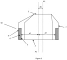
- Figure 5 is a view of an air cap 50 according to the present disclosure cut on its diameter: the air cap 50 comprises an open circular bottom end 3, an open top circular end 2 parallel with the open circular bottom end 3.
- the open circular bottom end 3 is characterized by a first central axis A1, and the open circular top end 3 is characterized by a second central axis A2.
- the open circular bottom end 3 and the open top circular end 2 are not concentric, so the two axis A1 and A2 do not superpose and are separated by a distance d8.
- the circular wall 7 extending from the bottom end 3 to the top end 2 of the air cap 50 comprises an external thread 6, and the external thread 6 is concentric with the open circular bottom end 3, but not with the open top circular end 2, as shown on figure 4 by the fact that the distance d7 from the first central axis A1 to the root 5 of the thread 6 on one side is equal to the opposite distance d7 from the first central axis A1 to the root of the thread 6.
Landscapes
- Chemical & Material Sciences (AREA)
- Organic Chemistry (AREA)
- Chemical Kinetics & Catalysis (AREA)
- Nozzles (AREA)
- Closures For Containers (AREA)
Abstract
The present disclosure is related to the field of chemical engineering, in particular spraying devices. The present disclosure provides an air cap for an atomization nozzle, wherein the air cap comprises an open circular top end comprising a circular opening, an open circular bottom end parallel to the open circular top end, said open circular bottom end comprising a circular opening, and a circular wall extending from said open circular bottom end to said open circular top end, said circular wall comprising a thread extending from the bottom end of the circular wall, wherein said thread and is positioned eccentric with respect to the opening of the open circular top end.
Description
- The present disclosure is related to the field of chemical engineering, in particular spraying devices.
- The manufacture of industrial products, such as fertilizers, requires different steps and processes. A process found in many manufacturing lines involves the spraying of a liquid composition as fine droplets. Such spraying process may be used to coat particles with a coating composition or to produce granules by spraying the liquid composition onto seed particles.
- Granulation is a process wherein a liquid feed is sprayed inside a container comprising particles in movement. The liquid feed is divided into small droplets that come into contact with the particles comprised in the container and solidify on the particles. This mechanism leads to a growth of the particle size until the desired size is obtained.
- Different sub-types of granulation exist, such as pan granulation, drum granulation, and fluidized bed granulation, but they all rely on the same principle described above.
- Spraying the liquid feed as small droplets is usually done using spraying devices. Such devices continuously receive a liquid feed and inject via its nozzle this feed into the granulator in the form of droplets which size may vary.
- Different types of nozzles can be used depending on factors, such as nature of the liquid feed, and the type of granulator. Examples of nozzles include pneumatic nozzles, and atomization nozzles.
- Atomization nozzles are devices that require a feed of a compressed gas and a liquid feed. The atomization nozzles combine the gas feed and the liquid feed, such that liquid droplets exit the nozzle and enter the granulator. Spraying devices comprising atomization nozzles are assembled inside a granulator at the end of the pipes carrying the liquid feed and the gas feed.
- A new air cap for a spraying device comprising an atomization nozzle has been designed. The new design allows to correct situations where the melt injection line and the air injection line are not concentric, which may lead to a sub-optimal spraying pattern and granulation operations.
- In a first aspect, the present disclosure provides an air cap for an atomization nozzle, wherein the air cap comprises an open circular top end comprising a circular opening, an open circular bottom end parallel to the open circular top end, said open circular bottom end comprising a circular opening, and a circular wall extending from said open circular bottom end to said open circular top end, said circular wall comprising a thread extending from the bottom end of the circular wall, wherein said thread and is positioned eccentric with respect to the opening of the open circular top end.
- In another aspect, the present disclosure provides a granulator comprising a plurality of atomization nozzles, one or more conventional air cap, and one or more air cap according to the present disclosure, wherein:
- the conventional air comprises a circular wall defining an open bottom end comprising ac circular opening, an open top end comprising a circular opening, the open top end being parallel to the open bottom end, and the opening of the open bottom end and the opening of the open top end being concentric;
- the circular wall of the conventional air cap comprises a thread extending from its bottom end, the thread being concentric with the opening of the open top end of the conventional air cap.
- The following description of the figure of a specific embodiment of a system according to the present disclosure is only given by way of example and is not intended to limit the present explanation, its application or use. In the figure, identical reference numerals refer to the same or similar parts and features.
-
Figure 1 is a view of a conventional air cap, wherein the thread of the circular wall is positioned concentric with the circular opening of the top end of the air cap. -
Figure 2 is a view of an air cap according to the present disclosure. -
Figure 3 is a view of another air cap according to the present disclosure. -
Figure 4 is a view of another air cap according to the present disclosure. -
Figure 5 is a view of another air cap according to the present disclosure. - Unless otherwise defined, all terms used in disclosing the invention, including technical and scientific terms, have the meaning as commonly understood by one of ordinary skill in the art to which this invention belongs. By means of further guidance, term definitions are included to better appreciate the teaching of the present invention.
- All references cited in this description are hereby deemed to be incorporated in their entirety by way of reference.
- As used herein, the following terms have the following meanings:
"A", "an", and "the" as used herein refers to both singular and plural referents unless the context clearly dictates otherwise. By way of example, "a compartment" refers to one or more than one compartment. - "About" as used herein referring to a measurable value such as a parameter, an amount, a temporal duration, and the like, is meant to encompass variations of +/-20 % or less, in particular +/-10 % or less, more in particular +/-5 % or less, even more in particular +/-1 % or less, and still more in particular +/-0.1 % or less of and from the specified value, in so far such variations are appropriate to perform in the disclosed invention. However, it is to be understood that the value to which the modifier "about" refers is itself also specifically disclosed.
- "Comprise", "comprising", and "comprises" and "comprised of" as used herein are synonymous with "include", "including", "includes" or "contain", "containing", "contains" and are inclusive or open-ended terms that specifies the presence of what follows e.g. component and do not exclude or preclude the presence of additional, non-recited components, features, element, members, steps, known in the art or disclosed therein.
- The recitation of numerical ranges by endpoints includes all numbers and fractions subsumed within that range, as well as the recited endpoints.
- The expression "weight percent", "°/wt" or "weight%", here and throughout the description unless otherwise defined, refers to the relative weight of the respective component based on the overall weight of the formulation.
- For spraying devices comprising an atomization nozzle, a great variety of designs can be found, but they all follow the same general concept: the atomization nozzle is located at the end of a melt injection line which receives the liquid feed, and the spraying device also comprises an air cap which surrounds the melt injection line and is configured to receive a gas stream and guide the gas stream to generate liquid droplets.
- Air caps comprise a circular wall defining an open bottom end configured to receive a gas stream, an open top end, configured to release the gas stream. The bottom end is parallel to the top end, and the bottom end has a larger diameter than the top end. The opening of the top end and the opening of the bottom end are circular. In conventional air caps, the opening of the open bottom end and the opening of the open top end are concentric (see
figure 1 ). The circular wall comprises an internal or external thread extending from its bottom such that it can be screwed onto the air injection line. The thread is concentric with the opening of the open top end. - The design and geometry of atomization nozzles can vary greatly, but one important feature for all atomization nozzles is that the opening of the air cap needs to be concentric with the melt injection line and the nozzle. This ensures a symmetrical spraying pattern of the liquid droplets, which is very important for the stability and reliability of the granulator operations.
- In some cases, it was observed that it was difficult to install spraying devices comprising an atomization nozzle and an air cap, such that the opening of the air cap was concentric with the nozzle. In particular, this was the case when installing nozzles in a granulator wherein the ends of the pipes carrying the liquid feed and gas feed were not concentric. Typically, the pipe carrying the liquid feed to a nozzle is located inside the pipe carrying the gas feed, and both pipes should be concentric. However, it was found in some cases that such geometry was impossible to achieve perfectly: the two pipes entering the granulator are welded to the feed lines, and due to the length of the pipes, a very small error on the weld causes a deviation of 1 or 2 mm at the nozzle, which is enough to create an unsatisfactory spraying pattern. The result was that, after installation of the nozzle and the air cap, the opening of the air cap was not concentric with the nozzle and the nozzle created an unsymmetrical spraying pattern.
- It has now been found that it is possible to correct that geometrical default by designing new air caps. In an air cap according to the present disclosure, the thread of the circular wall extending from the bottom of the air cap and the open top end of the air cap are not concentric. In other words, the axis of symmetry of the opening of the open top end does not coincide with the axis of symmetry of the thread.
- The thread of the circular wall defines a circumference that is positioned eccentric with respect to the circular opening of the top end of the air cap.
- As used herein, the bottom end of the air cap always refers to the end with the larger diameter. The air cap is configured such that the gas stream enters the air cap from its bottom end and leaves the air cap at the top end.
- In a first aspect, the present disclosure provides an air cap for an atomization nozzle, wherein the air cap comprises an open circular top end comprising a circular opening, an open circular bottom end parallel to the open circular top end, said open circular bottom end comprising a circular opening, and a circular wall extending from said open circular bottom end to said open circular top end, said circular wall comprising a thread extending from the bottom end of the circular wall, wherein said thread and is positioned eccentric with respect to the opening of the open circular top end.
- The air cap according to the present disclosure is configured to be screwed and welded onto the threaded end of an air injection line to ensure that the air cap does not move during the operation of the granulator. The fact that the thread of the circular wall and the opening of the open circular top end of the air cap are eccentric ensures that it is possible to find a position along the thread wherein the opening of the open circular top end of the air cap and the nozzle are concentric, ensuring an optimum spraying pattern.
- In some embodiments, an air cap according to the present disclosure can be similar to a conventional air cap in that the opening of the open bottom end of the circular wall and the opening of the open top end of the circular wall are concentric, but the thread is eccentric with the opening of the open top end.
- In some embodiments, the opening of the open circular top end and the opening of the open circular bottom end are eccentric.
- In some embodiments, the opening of the open circular top end and the opening of the open circular bottom end are concentric.
- In some embodiments, the open circular top end and the open circular bottom end are eccentric.
- In some embodiments, the opening of the open circular top end and the opening of the open circular bottom end are concentric.
- In some embodiments, the opening of the open bottom end of the circular wall and the opening of the open top end of the circular wall are eccentric, and the thread is concentric with the opening of the open bottom end and eccentric with the opening of the open top end.
- In some embodiments, the distance between the first central axis of the thread and the second central axis of the open circular top end is from 0.5 to 5.0 mm. In industrial granulators, it was often observed that the non-alignment of the air feed and melt feed to the atomization nozzle was only off by a few millimeters. An air cap according to the present disclosure wherein the distance between its first and second central axis is from 0.5 and 5.0 mm was enough to compensate this non-alignment.
- In some embodiments, the diameter of the bottom end of the air cap is from 40 to 60 mm. The diameter of the air cap depends on the dimensions of the granulator and the dimensions of atomization nozzles comprised in the granulator.
- In some embodiments, the diameter of the top end of the air cap is from 20 to 30 mm.
- In some embodiments, the air cap is made of metal, in particular of stainless steel, such as 304 or 316 stainless steel. In some embodiments, the liquid injected by the nozzles is corrosive, and the air cap must be made in a material resistant to corrosion.
- In some embodiments, the height of the thread is from 20 to 30 mm.
- In another aspect, the present disclosure provides a granulator comprising a plurality of atomization nozzles, one or more conventional air cap, and one or more air cap according to the present disclosure, wherein:
- the conventional air comprises a circular wall defining an open bottom end comprising ac circular opening, an open top end comprising a circular opening, the open top end being parallel to the open bottom end, and the opening of the open bottom end and the opening of the open top end being concentric;
- the circular wall of the conventional air cap comprises a thread extending from its bottom end, the thread being concentric with the opening of the open top end of the conventional air cap.
- In some embodiments, the granulator is a fluidized bed granulator, a drum granulator, or a pan granulator.
- A granulator, such as a fluidized bed granulator may contain from 10 to 500 atomization nozzles. The number of nozzles depends on factors such as the size of the granulator and the desired production rate. It may be that only a fraction of the atomization nozzles requires an air cap according to the present disclosure while the other fraction can be equipped with conventional air caps, wherein the opening of the open circular bottom end of a conventional air cap is concentric with the opening of the open circular top end of a conventional air cap.
-
Figure 1 is a view of aconventional air cap 10 cut on its diameter: theair cap 10 comprises an open circularbottom end 3, an open topcircular end 2 parallel and the opening of the open circularbottom end 3 is concentric with the opening of the open circulartop end 2. The open circularbottom end 3 is characterized by a first central axis A1, and the open circulartop end 2 is characterized by a second central axis A2. Since the two ends are concentric, the two axis A1 and A2 superpose. Thecircular wall 7 extending from thebottom end 3 to thetop end 2 of theair cap 10 comprises aninternal thread 6 extending from the bottom end.Line 4 represents the crest ofthread 6, andline 5 the root ofthread 6. -
Figure 2 is a view of anair cap 20 according to the present disclosure cut on its diameter: theair cap 20 comprises an open circularbottom end 3, an open topcircular end 2 parallel with the open circularbottom end 3. The open circularbottom end 3 is characterized by a first central axis A1, and the open circulartop end 3 is characterized by a second central axis A2. The open circularbottom end 3 and the open topcircular end 2 are concentric, so the two axis A1 and A2 superpose. Thecircular wall 7 extending from thebottom end 3 to thetop end 2 of theair cap 20 comprises aninternal thread 6, and theinternal thread 6 is not concentric with the open circularbottom end 3 and the opening of the open topcircular end 2, as shown onfigure 2 by the fact that the distance d1 from the exterior side of thewall 7 to theroot 5 of thethread 6 on one side is different than the opposite distance d2 from the exterior side of thewall 7 to the root of thethread 6. -
Figure 3 is a view of anair cap 30 according to the present disclosure cut on its diameter: theair cap 30 comprises an open circularbottom end 3, an open topcircular end 2 parallel with the open circularbottom end 3. The open circularbottom end 3 is characterized by a first central axis A1, and the open circulartop end 3 is characterized by a second central axis A2. The open circularbottom end 3 and the open topcircular end 2 are concentric, so the two axis A1 and A2 superpose. Thecircular wall 7 extending from thebottom end 3 to thetop end 2 of theair cap 20 comprises anexternal thread 6, and theexternal thread 6 is not concentric with the open circularbottom end 3 and the opening of the open topcircular end 2, as shown onfigure 3 by the fact that the distance d3 from the central axis A1 of the open circularbottom end 3 to theroot 5 of thethread 6 on one side is different than the opposite distance d4 from the central axis A1 of the open circularbottom end 3 to the root of thethread 6. -
Figure 4 is a view of anair cap 40 according to the present disclosure cut on its diameter: theair cap 40 comprises an open circularbottom end 3, an open topcircular end 2 parallel with the open circularbottom end 3. The open circularbottom end 3 is characterized by a first central axis A1, and the open circulartop end 3 is characterized by a second central axis A2. The open circularbottom end 3 and the open topcircular end 2 are not concentric, so the two axis A1 and A2 do not superpose and are separated by a distance d6. Thecircular wall 7 extending from thebottom end 3 to thetop end 2 of theair cap 40 comprises aninternal thread 6, and theinternal thread 6 is concentric with the open circularbottom end 3, but not with the open topcircular end 2, as shown onfigure 4 by the fact that the distance d5 from the exterior side of thewall 7 to theroot 5 of thethread 6 on one side is equal to the opposite distance d5 from the exterior side of thewall 7 to the root of thethread 6. -
Figure 5 is a view of anair cap 50 according to the present disclosure cut on its diameter: theair cap 50 comprises an open circularbottom end 3, an open topcircular end 2 parallel with the open circularbottom end 3. The open circularbottom end 3 is characterized by a first central axis A1, and the open circulartop end 3 is characterized by a second central axis A2. The open circularbottom end 3 and the open topcircular end 2 are not concentric, so the two axis A1 and A2 do not superpose and are separated by a distance d8. Thecircular wall 7 extending from thebottom end 3 to thetop end 2 of theair cap 50 comprises anexternal thread 6, and theexternal thread 6 is concentric with the open circularbottom end 3, but not with the open topcircular end 2, as shown onfigure 4 by the fact that the distance d7 from the first central axis A1 to theroot 5 of thethread 6 on one side is equal to the opposite distance d7 from the first central axis A1 to the root of thethread 6.
Claims (10)
- An air cap for an atomization nozzle, wherein the air cap (1) comprises an open circular top end (2) comprising a circular opening, an open circular bottom end (3) parallel to the open circular top end, said open circular bottom end (3) comprising a circular opening, and a circular wall (7) extending from said open circular bottom end (3) to said open circular top end (2), said circular wall (7) comprising a thread (6) extending from the bottom end of the circular wall, characterized in that said thread (6) is positioned eccentric with respect to the opening of the open circular top end (2).
- An air cap according to claim 1, wherein the open circular top end (2) and the open circular bottom end (3) are concentric.
- An air cap according to claim 1, wherein the open circular top end (2) and the open circular bottom end (3) are eccentric.
- An air cap according to any one of claims 1 to 3, wherein the thread (6) is internal or external to the circular wall (7).
- An air cap according to any one of claims 1 to 4, wherein the open circular bottom end (3) comprises a central axis (A1), the open circular top end (2) comprises a central axis (A2), and the distance (d) between the central axis (A1) of the open circular bottom end (3) and the central axis (A2) of the open circular top end (2) is from 1.0 to 5.0 mm.
- An air cap according to any one of claims 1 to 5, wherein the diameter of the bottom end (3) is from 40 to 60 mm.
- An air cap according to any one of claims 1 to 6, wherein the diameter of the top end (2) is from 20 to 30 mm.
- An air cap according to any one of claims 1 to 7, wherein the height of the thread (6) is from 20 to 30 mm.
- A granulator comprising a plurality of atomization nozzles, one or more conventional air cap, and one or more air cap (1) according to any one of claims 1 to 8, wherein:- the conventional air comprises a circular wall defining an open bottom end comprising ac circular opening, an open top end comprising a circular opening, the open top end being parallel to the open bottom end, and the opening of the open bottom end and the opening of the open top end being concentric;- the circular wall of the conventional air cap comprises a thread extending from its bottom end, the thread being concentric with the opening of the open top end of the conventional air cap.
- The granulator according to claim 9, wherein the granulator is a fluidized bed granulator.
Priority Applications (4)
| Application Number | Priority Date | Filing Date | Title |
|---|---|---|---|
| EP23169393.8A EP4454763A1 (en) | 2023-04-24 | 2023-04-24 | Air cap for spraying device |
| PCT/EP2024/061155 WO2024223604A1 (en) | 2023-04-24 | 2024-04-24 | Air cap for spraying device |
| EP24721959.5A EP4701787A1 (en) | 2023-04-24 | 2024-04-24 | Air cap for spraying device |
| CN202480017837.9A CN120857980A (en) | 2023-04-24 | 2024-04-24 | Air cap for spraying equipment |
Applications Claiming Priority (1)
| Application Number | Priority Date | Filing Date | Title |
|---|---|---|---|
| EP23169393.8A EP4454763A1 (en) | 2023-04-24 | 2023-04-24 | Air cap for spraying device |
Publications (1)
| Publication Number | Publication Date |
|---|---|
| EP4454763A1 true EP4454763A1 (en) | 2024-10-30 |
Family
ID=86184929
Family Applications (2)
| Application Number | Title | Priority Date | Filing Date |
|---|---|---|---|
| EP23169393.8A Withdrawn EP4454763A1 (en) | 2023-04-24 | 2023-04-24 | Air cap for spraying device |
| EP24721959.5A Pending EP4701787A1 (en) | 2023-04-24 | 2024-04-24 | Air cap for spraying device |
Family Applications After (1)
| Application Number | Title | Priority Date | Filing Date |
|---|---|---|---|
| EP24721959.5A Pending EP4701787A1 (en) | 2023-04-24 | 2024-04-24 | Air cap for spraying device |
Country Status (3)
| Country | Link |
|---|---|
| EP (2) | EP4454763A1 (en) |
| CN (1) | CN120857980A (en) |
| WO (1) | WO2024223604A1 (en) |
Citations (6)
| Publication number | Priority date | Publication date | Assignee | Title |
|---|---|---|---|---|
| DE2017279A1 (en) * | 1969-04-14 | 1971-03-25 | Gulf Oil Canada Ltd , Toronto, Ontario (Kanada) | Method and device for dusting liquids, in particular for oil spray burners |
| US4619843A (en) * | 1983-08-27 | 1986-10-28 | Unie Van Kunstmestfabrieken B.V. | Process for the preparation of granules |
| US5344078A (en) * | 1993-04-22 | 1994-09-06 | Ransburg Corporation | Nozzle assembly for HVLP spray gun |
| KR101254597B1 (en) * | 2012-11-21 | 2013-04-15 | (주)대진코퍼레이션 | Injection nozzle for coating inner wall of mold for a centrifugal casting |
| AU2012286837A1 (en) * | 2011-07-28 | 2014-02-20 | 3M Innovative Properties Company | Spray head assembly with integrated air cap/nozzle for a liquid spray gun |
| RU2571133C2 (en) * | 2011-02-09 | 2015-12-20 | Зм Инновейтив Пропертиз Компани | Nozzle adapters and paint blower spraying head components |
Family Cites Families (2)
| Publication number | Priority date | Publication date | Assignee | Title |
|---|---|---|---|---|
| US979955A (en) * | 1910-01-11 | 1910-12-27 | James H Hulings | Nozzle. |
| GB475751A (en) * | 1936-07-25 | 1937-11-25 | John Berchmans Blake | Improvements in nozzles for hose pipes |
-
2023
- 2023-04-24 EP EP23169393.8A patent/EP4454763A1/en not_active Withdrawn
-
2024
- 2024-04-24 CN CN202480017837.9A patent/CN120857980A/en active Pending
- 2024-04-24 WO PCT/EP2024/061155 patent/WO2024223604A1/en not_active Ceased
- 2024-04-24 EP EP24721959.5A patent/EP4701787A1/en active Pending
Patent Citations (6)
| Publication number | Priority date | Publication date | Assignee | Title |
|---|---|---|---|---|
| DE2017279A1 (en) * | 1969-04-14 | 1971-03-25 | Gulf Oil Canada Ltd , Toronto, Ontario (Kanada) | Method and device for dusting liquids, in particular for oil spray burners |
| US4619843A (en) * | 1983-08-27 | 1986-10-28 | Unie Van Kunstmestfabrieken B.V. | Process for the preparation of granules |
| US5344078A (en) * | 1993-04-22 | 1994-09-06 | Ransburg Corporation | Nozzle assembly for HVLP spray gun |
| RU2571133C2 (en) * | 2011-02-09 | 2015-12-20 | Зм Инновейтив Пропертиз Компани | Nozzle adapters and paint blower spraying head components |
| AU2012286837A1 (en) * | 2011-07-28 | 2014-02-20 | 3M Innovative Properties Company | Spray head assembly with integrated air cap/nozzle for a liquid spray gun |
| KR101254597B1 (en) * | 2012-11-21 | 2013-04-15 | (주)대진코퍼레이션 | Injection nozzle for coating inner wall of mold for a centrifugal casting |
Also Published As
| Publication number | Publication date |
|---|---|
| EP4701787A1 (en) | 2026-03-04 |
| CN120857980A (en) | 2025-10-28 |
| WO2024223604A1 (en) | 2024-10-31 |
Similar Documents
| Publication | Publication Date | Title |
|---|---|---|
| EP2048112A1 (en) | Use of a nozzle for manufacturing sodium percarbonate | |
| EP2739400B1 (en) | Pressurized air assisted spray nozzle assembly | |
| CN1278781C (en) | Spray gun | |
| US6322003B1 (en) | Air assisted spray nozzle | |
| TWI322712B (en) | Fluid atomizing system and spray device | |
| US20040159720A1 (en) | Air assisted spray nozzle assembly for spraying viscous liquids | |
| KR102168146B1 (en) | Full cone air-assisted spray nozzle assembly | |
| KR102262760B1 (en) | Metal powder manufacturing apparatus and its gas injector and crucible | |
| CN1277619C (en) | Fluid bed granulation apparatus | |
| US9925508B2 (en) | Catalytic cracking spray nozzle with internal liquid particle dispersion ring | |
| WO2015042283A1 (en) | High efficiency/low pressure catalytic cracking spray nozzle assembly | |
| KR20200096403A (en) | Metal powder producing apparatus and gas jet device for same | |
| JP5065271B2 (en) | Method for producing urea pellets | |
| EP3046678A1 (en) | Spray nozzle for fluidized catalytic cracking | |
| WO2011133342A1 (en) | External mix air assisted spray nozzle assembly | |
| WO2024223604A1 (en) | Air cap for spraying device | |
| RU2150336C1 (en) | Finely divided liquid sprayer | |
| AU2017326640B2 (en) | Spray nozzle assembly with one piece spray nozzle and quick disconnect retention cap | |
| WO1981002855A1 (en) | Process for the spraying of a liquid | |
| DE10116051B4 (en) | Spray nozzle for fluidized bed plants | |
| US20130082120A1 (en) | Spray device having curved passages | |
| JPH0290957A (en) | Spray nozzle and granulation coating device using it | |
| WO2015042278A1 (en) | Catalytic cracking spray nozzle with extended liquid inlet | |
| WO2022084034A1 (en) | Nozzle for spraying substances and method for the open-loop or closed-loop control of the nozzle | |
| JPH08199207A (en) | Method and apparatus for producing metal powder |
Legal Events
| Date | Code | Title | Description |
|---|---|---|---|
| PUAI | Public reference made under article 153(3) epc to a published international application that has entered the european phase |
Free format text: ORIGINAL CODE: 0009012 |
|
| STAA | Information on the status of an ep patent application or granted ep patent |
Free format text: STATUS: THE APPLICATION HAS BEEN PUBLISHED |
|
| AK | Designated contracting states |
Kind code of ref document: A1 Designated state(s): AL AT BE BG CH CY CZ DE DK EE ES FI FR GB GR HR HU IE IS IT LI LT LU LV MC ME MK MT NL NO PL PT RO RS SE SI SK SM TR |
|
| STAA | Information on the status of an ep patent application or granted ep patent |
Free format text: STATUS: THE APPLICATION IS DEEMED TO BE WITHDRAWN |
|
| 18D | Application deemed to be withdrawn |
Effective date: 20250501 |