EP4454682A2 - Nadeleinführ- und retraktionsmechanismus - Google Patents
Nadeleinführ- und retraktionsmechanismus Download PDFInfo
- Publication number
- EP4454682A2 EP4454682A2 EP24194453.7A EP24194453A EP4454682A2 EP 4454682 A2 EP4454682 A2 EP 4454682A2 EP 24194453 A EP24194453 A EP 24194453A EP 4454682 A2 EP4454682 A2 EP 4454682A2
- Authority
- EP
- European Patent Office
- Prior art keywords
- needle
- carrier
- control element
- retraction
- spring member
- Prior art date
- Legal status (The legal status is an assumption and is not a legal conclusion. Google has not performed a legal analysis and makes no representation as to the accuracy of the status listed.)
- Pending
Links
Images


Classifications
-
- A—HUMAN NECESSITIES
- A61—MEDICAL OR VETERINARY SCIENCE; HYGIENE
- A61M—DEVICES FOR INTRODUCING MEDIA INTO, OR ONTO, THE BODY; DEVICES FOR TRANSDUCING BODY MEDIA OR FOR TAKING MEDIA FROM THE BODY; DEVICES FOR PRODUCING OR ENDING SLEEP OR STUPOR
- A61M5/00—Devices for bringing media into the body in a subcutaneous, intra-vascular or intramuscular way; Accessories therefor, e.g. filling or cleaning devices, arm-rests
- A61M5/14—Infusion devices, e.g. infusing by gravity; Blood infusion; Accessories therefor
- A61M5/158—Needles for infusions; Accessories therefor, e.g. for inserting infusion needles, or for holding them on the body
-
- A—HUMAN NECESSITIES
- A61—MEDICAL OR VETERINARY SCIENCE; HYGIENE
- A61M—DEVICES FOR INTRODUCING MEDIA INTO, OR ONTO, THE BODY; DEVICES FOR TRANSDUCING BODY MEDIA OR FOR TAKING MEDIA FROM THE BODY; DEVICES FOR PRODUCING OR ENDING SLEEP OR STUPOR
- A61M5/00—Devices for bringing media into the body in a subcutaneous, intra-vascular or intramuscular way; Accessories therefor, e.g. filling or cleaning devices, arm-rests
- A61M5/14—Infusion devices, e.g. infusing by gravity; Blood infusion; Accessories therefor
- A61M5/142—Pressure infusion, e.g. using pumps
- A61M5/14244—Pressure infusion, e.g. using pumps adapted to be carried by the patient, e.g. portable on the body
- A61M5/14248—Pressure infusion, e.g. using pumps adapted to be carried by the patient, e.g. portable on the body of the skin patch type
-
- A—HUMAN NECESSITIES
- A61—MEDICAL OR VETERINARY SCIENCE; HYGIENE
- A61M—DEVICES FOR INTRODUCING MEDIA INTO, OR ONTO, THE BODY; DEVICES FOR TRANSDUCING BODY MEDIA OR FOR TAKING MEDIA FROM THE BODY; DEVICES FOR PRODUCING OR ENDING SLEEP OR STUPOR
- A61M5/00—Devices for bringing media into the body in a subcutaneous, intra-vascular or intramuscular way; Accessories therefor, e.g. filling or cleaning devices, arm-rests
- A61M5/14—Infusion devices, e.g. infusing by gravity; Blood infusion; Accessories therefor
- A61M5/158—Needles for infusions; Accessories therefor, e.g. for inserting infusion needles, or for holding them on the body
- A61M2005/1583—Needle extractors
-
- A—HUMAN NECESSITIES
- A61—MEDICAL OR VETERINARY SCIENCE; HYGIENE
- A61M—DEVICES FOR INTRODUCING MEDIA INTO, OR ONTO, THE BODY; DEVICES FOR TRANSDUCING BODY MEDIA OR FOR TAKING MEDIA FROM THE BODY; DEVICES FOR PRODUCING OR ENDING SLEEP OR STUPOR
- A61M5/00—Devices for bringing media into the body in a subcutaneous, intra-vascular or intramuscular way; Accessories therefor, e.g. filling or cleaning devices, arm-rests
- A61M5/14—Infusion devices, e.g. infusing by gravity; Blood infusion; Accessories therefor
- A61M5/158—Needles for infusions; Accessories therefor, e.g. for inserting infusion needles, or for holding them on the body
- A61M2005/1585—Needle inserters
-
- A—HUMAN NECESSITIES
- A61—MEDICAL OR VETERINARY SCIENCE; HYGIENE
- A61M—DEVICES FOR INTRODUCING MEDIA INTO, OR ONTO, THE BODY; DEVICES FOR TRANSDUCING BODY MEDIA OR FOR TAKING MEDIA FROM THE BODY; DEVICES FOR PRODUCING OR ENDING SLEEP OR STUPOR
- A61M2205/00—General characteristics of the apparatus
- A61M2205/58—Means for facilitating use, e.g. by people with impaired vision
- A61M2205/581—Means for facilitating use, e.g. by people with impaired vision by audible feedback
-
- A—HUMAN NECESSITIES
- A61—MEDICAL OR VETERINARY SCIENCE; HYGIENE
- A61M—DEVICES FOR INTRODUCING MEDIA INTO, OR ONTO, THE BODY; DEVICES FOR TRANSDUCING BODY MEDIA OR FOR TAKING MEDIA FROM THE BODY; DEVICES FOR PRODUCING OR ENDING SLEEP OR STUPOR
- A61M2205/00—General characteristics of the apparatus
- A61M2205/58—Means for facilitating use, e.g. by people with impaired vision
- A61M2205/583—Means for facilitating use, e.g. by people with impaired vision by visual feedback
-
- A—HUMAN NECESSITIES
- A61—MEDICAL OR VETERINARY SCIENCE; HYGIENE
- A61M—DEVICES FOR INTRODUCING MEDIA INTO, OR ONTO, THE BODY; DEVICES FOR TRANSDUCING BODY MEDIA OR FOR TAKING MEDIA FROM THE BODY; DEVICES FOR PRODUCING OR ENDING SLEEP OR STUPOR
- A61M2205/00—General characteristics of the apparatus
- A61M2205/58—Means for facilitating use, e.g. by people with impaired vision
- A61M2205/587—Lighting arrangements
-
- A—HUMAN NECESSITIES
- A61—MEDICAL OR VETERINARY SCIENCE; HYGIENE
- A61M—DEVICES FOR INTRODUCING MEDIA INTO, OR ONTO, THE BODY; DEVICES FOR TRANSDUCING BODY MEDIA OR FOR TAKING MEDIA FROM THE BODY; DEVICES FOR PRODUCING OR ENDING SLEEP OR STUPOR
- A61M2205/00—General characteristics of the apparatus
- A61M2205/82—Internal energy supply devices
- A61M2205/8206—Internal energy supply devices battery-operated
Definitions
- the present invention relates to a needle insertion and retraction mechanism for a medication delivery device for delivering a medicament.
- the medication delivery device may be an infusion device or an infusion pump.
- the medication delivery device may be a so-called patch pump, patch injector or bolus injector, that is adhered to the skin of the patient, for example, by virtue of an adhesive layer.
- the mechanism may have a needle insertion mechanism for insertion of a needle or a soft cannula into the skin of the patient for subcutaneous delivery of a medicament.
- Devices for delivery of medication to the patient which are particularly adhered to the skin of the patient, have been developed, either for delivery of multiple adjustable doses super imposed on a basal rate ( WO 02/40083 A2 ), or for multiple fix doses including a basal rate ( WO 2011/046950 Al ).
- Those devices have been preliminary developed for the treatment of diabetes, but also for the treatment of other diseases like cardio vascular diseases, auto-immune diseases or cancer for the delivery of a single dose as described in WO 2010/029054 Al , for example.
- Such a device is adhered to the patient's skin and activated automatically, or by the use of an activation button, or via a remote control system if the device is enabled to connect to other devices, and subsequently a single bolus volume will be injected.
- medicament includes any flowable medical formulation suitable for controlled administration through a means such as, for example, a cannula or a hollow needle and comprises a liquid, a solution, a gel or fine suspension containing one more medical active ingredients.
- a medicament can be a composition comprising a single active ingredient or a pre-mixed or co-formulated composition with more than one active ingredient present in a single container.
- Medication includes drugs such as peptides (e.g.
- insulin insulin, insulin-containing drugs, GLP-1 containing drugs or delivered or analogous preparations
- proteins and hormones active ingredients derived from or harvested by biological sources, active ingredients based on hormones or genes, nutritional formulations, enzymes and other substances in both solid (suspended) or liquid form but also polysaccharides, vaccines, DNA, RNA, oligonucleotides, antibodies or parts of antibodies but also appropriated basic, auxiliary and carrier substances.
- a needle insertion and retraction mechanism for a medication delivery device is disclosed in WO 2017/219155 Al , WO 2006/108809 A1 , WO 2018/024625 A1 , GB 2552340 A , WO 2016/053954 A1 , US 2013/060233 A1 , for example.
- the terms “substance”, “drug”, “medicament” and “medication” are to be understood to include any flowable medical formulation suitable for controlled administration through a means such as, for example, a cannula or a hollow needle, and comprises a liquid, a solution, a gel or a fine suspension containing one or more medical active ingredients.
- a medicament can be a composition comprising a single active ingredient or a pre-mixed or co-formulated composition with more than one active ingredient present in a single container.
- Medication includes drugs such as peptides (e.g., insulin, insulin-containing drugs, GLP-1 containing drugs or derived or analogous preparations), proteins and hormones, active ingredients derived from, or harvested by, biological sources, active ingredients based on hormones or genes, nutritional formulations, enzymes and other substances in both solid (suspended) or liquid form but also polysaccharides, vaccines, DNA, RNA, oligonucleotides, antibodies or parts of antibodies but also appropriate basic, auxiliary and carrier substances
- drugs such as peptides (e.g., insulin, insulin-containing drugs, GLP-1 containing drugs or derived or analogous preparations), proteins and hormones, active ingredients derived from, or harvested by, biological sources, active ingredients based on hormones or genes, nutritional formulations, enzymes and other substances in both solid (suspended) or liquid form but also polysaccharides, vaccines, DNA, RNA, oligonucleotides, antibodies or parts of antibodies but also appropriate basic, auxiliary and carrier substances
- distal is meant to refer to the direction or the end of the drug delivery device carrying an injection needle or an injection cannula
- proximal is meant to refer to the opposite direction or end pointing away from the needle or cannula
- injection system or "injector” refers to a device that is removed from the injection site after each medication event or drug delivery process
- injection system refers to a device with a cannula or needle that remains in the skin of the patient for a prolonged period of time, for example, several hours.
- the invention relates to a needle insertion and retraction mechanism, i.e. a mechanism which is adapted to automatically insert a needle and to automatically retract a needle.
- a medication delivery device particularly an infusion device or an infusion pump, may comprise the needle insertion and retraction mechanism disclosed herein.
- the medication delivery device may be formed as a patch pump, i.e. a medication delivery device which can be adhered to the skin of a human.
- the pump may be adhered to the skin by virtue of an adhesive layer provided on a surface of the housing of the medication delivery device.
- the medication delivery device may comprise at least a drive module and a needle insertion and retraction module.
- the drive module may have a drive motor and, for example, a controller for controlling the drive motor, a display, a battery casing and/or a battery to provide the energy for the drive motor, at least one control button, audible / visual indicators (e.g. LED lights).
- the drive module may comprise valuable components which are intended to be used multiple times.
- the needle insertion and retraction module may have the needle insertion and retraction mechanism disclosed herein.
- the needle insertion and retraction module may be adapted to be attached to the drive module.
- the housing of the drive module is adapted to be attached to the housing of the needle insertion and retraction module, e.g. in a detachable form fit.
- the drive module may be used multiple times whereas the needle insertion and retraction module which has been detached from the drive module may be disposed and replaced by a new needle insertion and retraction module.
- the product container which can be a carpule, for example, is emptied.
- the product container may be comprised by the needle insertion and retraction module. Therefore, the needle insertion and retraction module may comprise a product container holder adapted to retain a product container. If the product container is emptied, for example, the needle insertion and retraction module is detached from the drive module and replaced by a new one which comprises a new, i.e. filled, product container.
- the needle insertion and retraction module is adapted to be attached to the drive module such that the motor of the drive module is or can be operatively connected or is operatively connectable to a control element of the needle insertion and retraction module to move it transversely with respect to the longitudinal axis of the needle from a starting position via a needle insertion release position to a needle retraction release position as explained below.
- the needle insertion and retraction module comprises a drive shaft which has a coupling member and which is rotatable with respect to the housing of the needle insertion and retraction module.
- the drive shaft may be coupled with the control element such that rotation of the drive shaft in a first direction, particularly stepwise, results in linearly moving the control element, particularly stepwise, transversely with respect to thelongitudinal axis of the needle from a starting position via, for example, a needle insertion release position to a needle retraction release position.
- the drive module may have a drive shaft which is coupled to the drive motor and which comprises a second coupling member which is adapted to be connected with the first coupling member to transmit rotational movement of the drive shaft of the drive module in rotational movement of the drive shaft of the needle insertion and retraction module.
- the drive module may be adapted such that a rotational movement of the motor in one direction is transmitted in a rotational movement of the drive shaft of the needle insertion and retraction module, whereas rotational movement of the motor in the opposite direction is not transmitted to the drive shaft of the needle insertion and retraction module.
- rotation of the motor in the opposite direction may be used to drive a piston rod mechanism to expel medicament from the product container.
- the needle insertion and retraction mechanism for a medication delivery device for delivering a medicament may comprise a housing.
- the housing may be a single component housing or, expediently, a multi component housing comprising two or more housing parts. Two or more housing parts may simplify assembly of the needle insertion and retraction mechanism and/or simplifies injection moulding of the housing parts. Furthermore, different materials can be used for different requirements of the different parts of the housing.
- the needle insertion and retraction mechanism comprises a needle carrier, which holds a needle, i.e. a hollow needle.
- the needle is adapted to be inserted through the skin of a patient and to channel medication into the patient.
- the needles may particularly remain in the patient while the medicament is channeled, for example infused or injected, into the patient.
- a soft cannula particularly a flexible tube
- medicament is channeled, for example infused or injected, into the patient through the soft cannula while the needle is in its retracted position.
- the needle is fixedly connected to the needle carrier i.e. such that the needle cannot be detached from the needle carrier. Particularly movement of the needle carrier results in corresponding movement of the needle, and vice versa.
- the needle carrier can comprise a channel which is in fluid communication with the channel of the hollow needle.
- the needle carrier is linearly guided, particularly by the housing or another component of the needle insertion and retraction mechanism, to be moved along the longitudinal axis of the needle.
- the housing forms a linear guide which linearly guides the needle carrier.
- the needle insertion and retraction mechanism further comprises a first spring member and a second spring member.
- the first spring member is adapted to move the needle carrier with respect to the housing in a needle insertion direction along the longitudinal axis of the needle.
- the second spring member is adapted to retract the needle carrier with respect to the housing in a needle retraction direction, which is opposed to the needle insertion direction.
- the first spring member is provided in a pre-tensioned state, wherein releasing the first spring member causes the first spring member to operate on the needle carrier to move the needle carrier in the needle insertion direction.
- the second spring member is provided in a pre-tensioned state before the first spring member is released. Since the second spring member is provided in a pre-tensioned state the first spring member may advantageously be provided in smaller dimensions. In an option not representing the invention, tensioning the second spring member by moving the needle carrier in the needle insertion direction may be advantageous since it reduces the risk of creeping of the material which may be affected by a pre-tensioned spring.
- first spring member is a spring which is separate from a spring which forms the second spring member. Therefore, first and second spring members may be formed by a separate spring, respectively. In another exemplary embodiment, the first and second spring members are commonly formed by a spring such that the first and second spring members are sections of the same spring, respectively.
- the first spring member may directly or indirectly operate on the needle carrier. Additionally or alternatively, the second spring member may operate directly or indirectly on the needle carrier. If the spring member acts directly on the needle carrier it preferably contacts the needle carrier. In embodiments where the spring member indirectly operates on the needle carrier one or more intermediate members can be provided between the needle carrier and the spring member.
- the needle insertion and retraction mechanism further comprises a control element.
- the control element is intended or adapted to control the release of the first spring member to move the needle carrier in the longitudinal direction and the release of the second spring member to move the needle carrier in the needle retraction direction, for example.
- the control element is linearly movable, preferably guided by, for example, the housing, with respect to the housing to be moved transversely, particularly perpendicularly, with respect to the longitudinal axis of the needle, i.e. transversely with respect to the needle insertion direction and/or the needle retraction direction.
- the housing may form a linear guide.
- the control element may be moved, particularly stepwise, from a starting position via, for example, a needle insertion release position to a needle retraction release position.
- the control element is moved from the starting position to the needle insertion release position and from the needle insertion release position to the needle retraction release position in a first direction with respect to the housing, respectively.
- the control element is linearly moved in one direction only from the starting position to the needle insertion release position and then to a needle retraction release position.
- the control element can additionally be moved in the first direction into or via a spike insertion release position.
- the control element is operatively coupled to the needle carrier, for example, it may engage the needle carrier, to prevent the needle carrier from being moved in the needle insertion direction, when the control element is in its starting position.
- the pre-tensioned first spring member is operatively coupled to the needle carrier.
- the second spring member is decoupled from the needle carrier. If the second spring member is decoupled from the needle carrier, when the control element is in its starting position, the second spring member may be provided in a pre-tension state.
- the second spring may be coupled to the needle carrier when the control element is in its starting position, particularly in embodiments where the movement of the needle carrier in the needle insertion direction causes the second spring member to be tensioned.
- the control element When the control element is in its needle insertion release position, the control element is decoupled from the needle carrier, for example, it disengages the needle carrier, such that the first spring member drives the needle carrier including the needle, in the needle insertion direction into a needle insertion position.
- the control element when the control element is moved from the starting position in the first direction to the needle insertion release position, the control element is decoupled from the needle carrier when the control element reaches the needle insertion release position. Since the first spring member, indirectly or directly, operates on the needle carrier it drives the needle carrier in the needle insertion direction until the needle carrier abuts a stop when the needle insertion position is reached.
- the first spring member may retain the needle carrier in the needle insertion position, for example, until retraction is triggered or the control element is moved in the needle retraction release position.
- the first spring member drives the needle carrier from a position, in which the needle is completely within the housing, i.e. the needle tip does not protrude from the outer surface of the housing, into the needle insertion position, in which the needle protrudes from the outer surface of the housing i.e. the needle tip protrudes by a distance from the housing corresponding to the desired insertion depth.
- the second spring member When the control element is in its needle retraction release position, the second spring member is operatively coupled to the needle carrier such that the second spring member drives the needle carrier in the needle retraction direction.
- the second spring member operates on the needle carrier, directly or indirectly, such that the spring member drives the needle carrier in the needle retraction direction, which is opposed to the needle insertion direction.
- the first spring member is decoupled from the needle carrier, when the control element is in its retraction release position.
- the second spring member is coupled to the needle carrier to drive it in the needle retraction direction.
- the first spring member may remain coupled to the needle carrier when the pre-tensioned second spring member is released such that the pre-tensioned second spring member both drives the needle carrier in the needle retraction direction and tensions the first spring member.
- the mechanism which causes the needle carrier to be retracted can be less complex since only the second spring member is to be operatively coupled to the needle carrier and the first spring member does not need to be decoupled from the needle carrier.
- the needle insertion and retraction mechanism may include a first intermediate member arranged between the first spring member and the needle carrier and/or a second intermediate member arranged between the second spring member and the needle carrier.
- Advantages of an intermediate member may be at least one of reducing friction, enhancing reliability of the mechanism and reducing the requirement to small tolerances regarding the dimension of the spring member.
- the first intermediate member may be linearly guided by the control element in the needle insertion direction.
- the control element may form a linear guide to guide the first intermediate member linearly.
- the first intermediate member may be connected to the control element such that it is linearly guided in the needle insertion direction. Because of the first intermediate member is linearly guided by the control element, it is movable together with the control element when the control element is moved from the starting position in the first direction or via the needle insertion release position to the needle retraction release position. Hence, the first intermediate member is linearly movable with respect to the control element in the needle insertion direction and is movable together with the control element transversely with respect to the needle insertion direction.
- the first intermediate member or the first spring member directly may be engaged with the needle carrier, when the control element is in its starting position.
- the needle carrier may be engaged with the control element, when the control element is in its starting position, whereby movement of the needle carrier in the needle insertion direction is prevented.
- the control member is adapted to be disengaged from the needle carrier by moving the control element transversely with respect to the needle insertion direction, i.e. in the first direction.
- the first spring member may operate in one embodiment directly on the needle carrier or in anther embodiment on the first intermediate member and the first intermediate member may operate on the needle carrier.
- the first spring member drives the first intermediate member and the needle carrier in the needle insertion direction.
- the first spring member drives the first intermediate member and the needle carrier until one of the needle carrier or the first intermediate member abuts a stop when the needle carrier is in the needle insertion position.
- the first intermediate member or the first spring member is adapted to be disengaged from the needle carrier by moving the control element particularly together with the first intermediate member transversely with respect to the needle insertion direction.
- the needle carrier By disengaging the first intermediate member or the first spring member from the needle carrier the needle carrier is free to be moved in the needle retraction direction.
- the second spring may drive the needle carrier together with the needle in the needle retraction direction provided the needle carrier is not prevented from being moved in the needle retraction direction otherwise.
- the first intermediate member may be dispensable, however, e.g. the requirements in view of small tolerances of the dimensions of the first spring member rise.
- the second intermediate member may be linearly guided by the control element in the needle retraction direction whereby the second intermediate member is linearly movable with respect to the control element in the needle retraction direction.
- the control element may form a linear guide for linearly guiding the second intermediate member in the needle retraction direction.
- the linear guide preferably prevents the second intermediate member from being moved with respect to the control element in the direction in which the control element is linearly guided. Therefore, the second intermediate member is movable together with the control element transversely with respect to the needle retraction direction.
- the second intermediate member or the second spring member may be adapted to be engaged with the housing, when the control element is in its starting position and/or in its insertion release position. Thereby, the second spring member can be retained in a pre-tensioned state, or prevented from being released.
- the second intermediate member or the second spring member When the second intermediate member or the second spring member is engaged with the housing, it may be disengaged from the needle carrier.
- the second intermediate member or the second spring member may be adapted to be disengaged from the housing and engaged with the needle carrier by moving the control element from its needle insertion release position transversely with respect to the needle retraction direction, particularly by moving the control element together with the second intermediate member in the first direction or particularly from the insertion release position to the needle retraction position.
- the second spring member By disengaging the second intermediate member or the second spring member from the housing and engaging it with the needle carrier the second spring member is able to drive and drives the second intermediate member and the needle carrier in the needle retraction direction.
- the second spring member in one embodiment directly operates on the needle carrier and in another embodiment on the second intermediate member and the second intermediate member operates on the needle carrier in the needle retraction direction.
- the second intermediate member may be dispensable, however, e.g. the requirements in view of small tolerances of the dimensions of the second spring member rise.
- the needle carrier By moving the needle carrier in the needle retraction direction into a needle retraction position, the needle is completely retracted or moved into the housing, i.e. such that the needle tip does not protrude from the outer surface of the housing.
- the first spring member comprises a spring arm and the first intermediate member or the needle carrier has a convexly curved contact surface on which the spring arm rests and particularly slides and/or rolls over when the first spring member drives the needle carrier or the first intermediate member together with the needle carrier into the needle insertion position. Because of the convexly curved contact surface the cooperation between the spring arm and the needle carrier or the first intermediate member can be optimised with respect to friction. The convexly curved contact surface effect that the spring arm slides and/or rolls over when the spring arm of the spring member drives the needle carrier or the first intermediate member together with the needle carrier in the needle insertion direction.
- the second spring member may comprise a spring arm and the second intermediate member or the needle carrier may have a convexly curved contact surface on which the spring arm of the second spring member rests, and particularly slides and/or rolls over when the second spring member drives the needle carrier or the second intermediate member together with the needle carrier into the needle retraction position. Because of the convexly curved contact surface the cooperation between the spring arm and the needle carrier or the second intermediate member can be optimised with respect to friction. The convexly curved contact surface effect that the spring arm slides and/or rolls over when the spring arm of the second spring member drives the needle carrier or the second intermediate member together with the needle carrier in the needle retraction direction.
- the first spring member and/or the second spring member may respectively be one of helical spring, a leaf spring, a compression spring, a pull spring, a torsion spring, a leg spring, a spiral spring, a belleville spring, or a combination thereof.
- the first spring member comprises a first spring arm and the second spring member comprises a second spring arm.
- the first spring arm operates directly or indirectly on the needle carrier.
- the first spring member may comprise a first resilient spring section which is adapted to store the spring energy for driving the needle carrier in the needle insertion direction.
- the second spring arm may operate directly or indirectly on the needle carrier.
- the second spring member may comprise a second resilient spring section for storing the spring energy to drive the needle carrier in the needle retraction direction.
- the first resilient spring section may be a torsion spring section, particularly a helical spring section which is torsionally loaded.
- the second resilient spring section may be a torsion spring member, particularly a helical spring section which is torsionally loaded.
- the first torsion spring section may be supported on the control element or the housing.
- the second torsion spring section may be supported on the control element or the housing.
- the first spring member and/or the second spring member are at least rotationally supported on the control member such that pivoting the arm of the respective spring member strains, i.e. tensions the spring, particularly the resilient spring section or the helical spring section.
- the first spring member and/or the second spring member may be located on the control element such that the respective spring member is movable together with the control element.
- the first spring member and/or the second spring member may be embedded in the control element, or the first and/or second spring members may partly surround a section of the control element.
- the helical section of the spring member surrounds a section, particularly a cylindrical section, of the control element.
- the section of the control element may extend through the helical spring section.
- the first spring member may be supported on the control element, wherein the first resilient spring section is located between where the first spring member is supported on the control element and where the first spring member, particularly the arm of the first spring member, operates directly or indirectly on the needle carrier. This effects that energy can be stored in the first resilient spring section by pivoting the arm, and releasing energy stored in the first resilient spring section pivots the arm in the opposite direction to drive the needle carrier in the needle insertion direction.
- the second spring member may be supported on the control element wherein the second resilient spring section is located between where the second spring member is supported on the control element and where the second spring member, particularly the arm of the second spring member, operates directly or indirectly on the needle carrier. This effects that energy can be stored in the second resilient spring section by pivoting the arm, and releasing energy stored in the second resilient spring section pivots the arm in the opposite direction to drive the needle carrier in the needle retraction direction.
- the first spring member may comprise a first arm which protrudes from the first resilient section and directly or indirectly operates on the needle carrier.
- the first arm is supported on the needle carrier or the first intermediate member.
- the second spring member may comprise a second arm which protrudes from the second resilient section and directly or indirectly operates on the needle carrier.
- the second arm is supported on the needle carrier or on the second intermediate member.
- the first spring member and the second spring member are integrally formed by one spring.
- one spring provides the functionality of the first spring member and the second spring member.
- the first resilient spring section and the second resilient spring section may be interconnected by an interconnecting section of the spring.
- the interconnecting section of the spring provides the support for the first and second spring members on the control element.
- the interconnecting section may be fixedly supported on the control element or at least supported such that rotation of the interconnecting section with respect to the control element about an axis about the first and second arms can be pivoted is prevented.
- the torsion spring section or the first and/or second resilient spring sections may be tensioned about an axis which extends transversally with respect to the longitudinal axis of the needle or the needle insertion or retraction directions.
- the spring or the first and second spring members may be made from a suitable material, e.g. a metal material, such as spring steel, alternatively plastic material or a hybrid between a plastic material and a metal.
- a suitable material e.g. a metal material, such as spring steel, alternatively plastic material or a hybrid between a plastic material and a metal.
- the spring may be a metal spring coated with plastic material.
- first and second spring members each are formed by a separate spring, or are integrally formed by one spring.
- the first spring member and the second spring member each comprise a resilient spring section, which may be selected from a torsion spring section or a helical spring section. In case a helical spring section is selected, then this section preferably surrounds a section of the control element.
- the needle insertion and retraction mechanism whereby the first spring member is supported on the control element and wherein a first resilient spring section is located between where the first spring member is supported on the control element and where the first spring member operates on the needle carrier, and/or the second spring member is supported on the control element and wherein a second resilient spring section is located between where the second spring member is supported on the control element and where the second spring member operates on the needle carrier.
- the first spring member comprises a first arm which protrudes from the first resilient section and operates on the needle carrier, for example is supported directly on the needle carrier or via a first intermediate member.
- the second spring member preferably comprises a second arm which protrudes from the second resilient section and operates directly on the needle carrier, for example is supported on the needle carrier or via the second intermediate member.
- the needle insertion and retraction mechanism whereby the first spring member and the second spring member are integrally formed by one spring, wherein the first resilient spring section and the second resilient spring section are interconnected by an interconnecting section of the spring, wherein the interconnecting section provides the support for the first and second spring members on the control element.
- the interconnecting section comprises a torsional or helical spring section.
- the needle insertion and retraction mechanism may comprise a spike carrier which holds or forms a hollow spike.
- the spike is intended to pierce a wall of a product container.
- the spike carrier is linearly guided, particularly by the housing, to be moved from a first position to a second position. In the first position the hollow spike does not pierce the wall of the container, whereas in the second position, the spike has pierced the wall of the product container.
- the spike may be arranged such that it axially aligns with the pierceable wall of the product container.
- the wall, particularly a septum or a stopper, of the product container may be made from an elastomer material such as rubber.
- the product container may be comprised by the needle insertion and retraction module which comprises the needle insertion and retraction mechanism.
- the needle insertion and retraction module comprises a retainer or (cartridge) holder adapted to retain and/or affix the product container.
- the retainer or holder may be a part of or formed by the housing.
- the hollow spike may be formed by or comprise a hollow needle.
- the spike may comprise a hollow body and a hollow needle, such as a transfer cannula, which is connected to the hollow body, particularly by material fit, such as bonding.
- the needle may be partially inserted in and fit to the hollow body, wherein the needle protrudes from the hollow body, such that, for example, the needle can pierce the wall of the product container.
- the hollow spike is adapted to pierce the wall of the product container when the spike is being moved from the first position to the second position.
- the tip of the spike is formed such that it can easily penetrate through the wall.
- the housing may comprise a linear guide which engages the spike carrier such that the spike carrier is movable from the first position to the second position.
- the hollow spike comprises a channel through which the medicament can be expelled from the container.
- the hollow spike and the needle are in fluid communication, preferably by virtue of a flexible tube, particularly comprising a lumen, which interconnects the hollow spike and the needle.
- a flexible tube particularly comprising a lumen, which interconnects the hollow spike and the needle.
- the lumen may either directly end into the channel of the needle, or into a channel of the needle carrier, wherein the channel of the needle carrier connects the lumen with the channel of the needle.
- the lumen may either directly end into the channel of the spike, or into a channel of the spike carrier, wherein the channel of the spike carrier connects the lumen with the channel of the spike.
- the spike carrier When the spike carrier is in its first position the needle is not in fluid communication with the medication. When the spike carrier is in its second position the needle is in fluid communication with the medication. This allows the spike and/or the medicament to be kept sterile. Furthermore, this allows that the fluid communication between the needle and the medicament may be established immediately before medication should be administered.
- the spike and/or the spike carrier can be moved in the second position before, during or after the needle and/or the needle carrier are moved in the needle insertion direction.
- a first step the needle and/or the needle carrier are moved into the needle insertion position.
- a second step for example, carried out later than the first step, the spike and/or the spike carrier are moved into the second position.
- the second step can be carried out before the first step.
- the spike carrier can be moved from the first position to the second position by, for example, a motor, one or more springs, one or more resilient parts, a drive such as a hydraulic drive or a pneumatic drive or an electromagnetic drive or a shape memory alloy driven drive, etc.
- the needle insertion and retraction mechanism or module comprises a spike insertion spring, which operates on the spike carrier to drive the spike carrier from the first position to the second position.
- the spike insertion spring can be supported on the housing and the spike carrier.
- the spring may be a leaf spring or a helical spring.
- the helical spring may be a conical helical spring or a cylindrical helical spring.
- a conical helical spring is advantageous as regards space saving since it can take up a very flat shape when it is compressed.
- the control element prevents the spike carrier from being moved from the first position to the second position.
- the control element may engage the spike carrier mechanically such that movement of the spike carrier from the first position to the second position is prevented.
- the spike carrier may be released to be moved from the first position to the second position.
- the control element is disengaged from the spike carrier by movement of the control element.
- the control element is released or disengaged from the spike carrier when the control element is moved from its starting position to a spike insertion release position. In the spike insertion release position, the control element releases or is disengaged from the spike carrier.
- the at least one of aforesaid drives particularly the spring or pre-tensioned spring, drives the spike carrier from the first position to the second position, thereby piercing the wall, particularly the septum, of the product container.
- the control element may be moved from the starting position in the first direction via the spike insertion release position, the needle insertion release position to the needle retraction release position. Particularly, the control element may be moved to the spike insertion release position and from the spike insertion release position to the needle insertion release position.
- control element can be moved in the needle insertion release position and from the needle insertion release position to the spike insertion release position. This effects that the needle is inserted before the spike pierces the wall of the product container. It is further conceivable that the spike insertion release position and the needle insertion release position coincide. This effects that the needle carrier and the spike carrier are moved in the needle insertion position or the second position at the same time.
- the longitudinal axis of the spike is transverse, particularly perpendicular, and offset with respect to the longitudinal axis of the needle. Therefore, the direction in which the spike carrier is guided is transverse, particularly perpendicular, to the direction in which the needle carrier is guided.
- a longitudinal product container such as a carpule
- the needle is perpendicular to the skin of the patient or the surface from which it protrudes if it is inserted.
- the needle insertion and retraction mechanism or module may comprise a drive shaft which is rotatably guided by the housing.
- the rotational axis of the rotational shaft can be arranged in parallel to the longitudinal axis of the spike and/or transverse, particularly perpendicular to the longitudinal axis of the needle.
- the rotational axis of the drive shaft may be offset from the longitudinal axis of the needle and/or from the longitudinal axis of the spike.
- the drive shaft is operatively connected to the control element such that rotation of the drive shaft in a first rotational direction causes the control element to be moved in a first longitudinal or linear direction from the starting position to at least one of the spike insertion release position, the needle insertion release position and the needle retraction release position.
- the drive shaft is driven gradually in the first rotational direction to move the control element gradually, i.e. stepwise, to aforesaid positions.
- the drive shaft may comprise a gear wheel, e.g. a pinion, which engages a gear rack formed by the control element. Thereby rotation of the drive shaft is converted in a linear or longitudinal movement of the control element.
- a gear wheel e.g. a pinion
- the drive shaft may comprise a coupling member adapted to be coupled with a coupling member of a drive shaft of a drive mechanism.
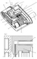
- the needle insertion and retraction mechanism 3 comprises a housing 10 which is a multiple component housing.
- the housing 10 comprises a first housing 11and a second housing 12 which are connected to each other by positive fit or by firmly bonding or welding.
- the first and the second housings 11, 12 are molded as a single part.
- the needle insertion and retraction mechanism 3 comprises a needle carrier 20 which holds a needle 25 ( Figure 2 ) and which is linearly guided by the housing 10, particularly by the first housing 11.
- the housing 10 or the first housing 11 comprises a longitudinal guide ( Figure 1 ) which engages the needle carrier 20 such that it is movable along the longitudinal axis of the needle 25.
- the longitudinal guide comprises at least a first longitudinal groove and a second longitudinal groove formed by the housing 11.
- the needle carrier 20 comprises at least a first rib and a second rib wherein the first rib engages the first groove and the second rib engages the second groove. Thereby the needle carrier 20 is linearly guided to be moved along the longitudinal axis of the needle 25.
- the needle carrier 20 is movable between an initial position ( Figure 1 ) in which the needle 25 which protrudes from the needle carrier 20 in a needle insertion direction is completely encompassed by the housing, and a needle insertion position ( Figures 6 and 7 ) in which the needle protrudes from an outer surface of the housing, particular the surface which is intended to be contacted or adhered to the skin of a patient.
- the housing 10 may comprise an opening or a pierceable wall through which the needle 25 is moved when the needle carrier 20 is moved from its initial position to its needle insertion position.
- the longitudinal axis of the needle 25 is substantially perpendicular or normal with respect to the surface which is intended to be adhered to the skin of the patient.
- the needle 25 is a hollow needle through which a medication or a medicament can be injected into the patient.
- the housing 10, particularly the housing 12 is adapted to retain a product container 4.
- the product container 4 is a carpule, with a pierceable septum 5 (wall) at its forward end.
- the medicament of the product container 4 can be expelled through a flexible tube 85 which is in fluid communication with the hollow needle 25 and through the needle 25 in a patient.
- the needle carrier 20 comprises a channel which connects an end of the flexible tube 85 and the hollow needle 25 in a fluid guiding manner.
- the needle 25 is fixedly retained in a bore of the needle carrier 20.
- the flexible tube 85 is with one end fixedly retained in a bore of the needle carrier 20.
- the other end of the flexible tube 85 is fixedly retained in a bore of a spike carrier 80 which connects a hollow spike 70 in a fluid guiding manner with the flexible tube 85, by means of a channel formed by the spike carrier 80.
- the spike 70 is fixedly retained in a bore of the spike carrier 80.
- One end of the flexible tube 85 is fixedly retained in a bore of the spike carrier 80.
- the needle insertion and retraction mechanism 3 further comprises a first spring member 31 which is adapted to move the needle carrier 20 with respect to the housing 10 in a needle insertion direction along the longitudinal axis of the needle 25. Furthermore, a second spring member 32 is provided which is adapted to retract the needle carrier 20 with respect to the housing 10 in a needle retraction direction, which is opposed to the needle insertion direction.
- the first spring member 31 and the second spring member 32 are integrally formed by one spring 30.
- spring members 31and 32 can be separate from one another.
- the first spring member 31 comprises a first helical spring section 31b which operates as a torsion spring ( Figure 8 ).
- a first arm 31a protrudes from the circumference of the first helical spring section 31b.
- the first spring member 31 is supported on a control element 40 such that the first helical spring section 31b can be strained or tensioned by pivoting the arm 31a. Furthermore, the energy stored in the first helical spring section 31b can be released whereby the first arm 31a is pivoted in a direction which causes the needle carrier 20 to move in the needle insertion direction.
- the second spring member 32 comprises a second helical spring section 32b which operates as a torsion spring.
- a second arm 32a protrudes from circumference of the second helical spring section 32b.
- the second spring member 32 is supported on the control element 40 such that the second helical spring section 32b can be strained or tensioned by pivoting the arm 32a. Furthermore, the energy stored in the second helical spring section 32b can be released whereby the second arm 32a is pivoted.
- the first helical spring section 31b and the second helical spring section 32b surround a portion of the control element 40.
- This portion comprises a slit which retains an interconnecting section 33 of the spring 30 which interconnects the first helical spring section 31b and the second helical spring section 32b and which also provides the support section of the first spring member 31 and the second spring member 32 for straining of tensioning the spring sections 31a and 31b.
- each of them can comprise a supporting section by which the spring member 31, 32 is supported on the control element 40.
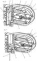
- a control element 40 is linearly guided with respect to the housing 10 to be moved transversely with respect to the longitudinal axis of the needle 25.
- the control element 40 can be moved from a starting position ( Figure 16 ) via a needle insertion release position ( Figure 17 ) to a needle retraction release position ( Figure 18 ).
- the control element 40 moves from the starting position to the needle retraction release position, including the positions between the starting position and the needle retraction release position, in the same direction.
- the spring 30 or the spring members 31, 32 are attached to the control element 40 such that they move together with the control element 40.
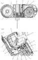
- the needle insertion and retraction mechanism 3 or module 2 provides for a drive shaft 15 which is rotatably guided by the housing 10, e.g. by virtue of a rotational bearing ( Figure 19 ).
- the drive shaft 15 is operatively connected to the control element 40.
- the drive shaft 15band the control element 40 are adapted to cooperate with each other such that rotation of the drive shaft 15 in a first rotational direction causes the control element 40 to be linearly moved, namely transversely with respect to the longitudinal axis of the needle 25 because of the linear guidance provided by the housing 10.
- the drive shaft 15 comprises a gear wheel 16 ( Figures 16 to 18 ) which is formed by or connected to the drive shaft 15 and which engages a gear rack 41formed by or connected to the control element 40. By rotating the drive shaft 15 or the gear wheel 16 the control element 40 is linearly moved.
- the drive shaft 15 comprises a coupling member 17 which is adapted to be coupled with a coupling member of a drive shaft of a drive mechanism (not shown). Thereby, rotation of the drive shaft 15 of the drive mechanism in a first direction is transmitted to the drive shaft 15 in the first direction causing the control element 40 to be moved in the first longitudinal direction.
- the control element 40 comprises a cap 42 which is connected to a main body 43 of the control element 40 ( Figure 1 ).
- the cap 42 is connected to or partially fits over the portion which is surrounded by the helical spring sections 31b, 32b.
- the cap 42 keeps the spring 30 or the spring members 31, 32 in position on the control element 40 or the main body 43 ( Figure 1 ).
- the control element 40 is operatively coupled to the needle carrier 20 to prevent the needle carrier 20 from being moved in the needle insertion direction when the control element 40 is in its starting position ( Figure 3 ).
- the control element 40 or its main body 43 comprises a stop surface 44 on which a counter stop surface 21 of the needle carrier 20 rests when the control element 40 is in its starting position.
- the needle carrier 20 is thereby prevented from being moved in the needle insertion direction.
- the stop surface 44 disengages the counter stop surface 21when the control element 40 is moved in its insertion release position such that the needle carrier 20 is free to be moved in the needle insertion direction.
- the first arm 31a or more generally the spring member 31 operates on the needle carrier 20 via a first intermediate member 50 ( Figure 5 ) to drive the needle carrier 20 form the initial position ( Figure 5 ) in the needle insertion direction into a needle insertion position ( Figure 6 ).
- a first intermediate member 50 comprises a counter stop surface 51 which engages a stop surface 22 of the needle carrier 20 when the control element 40 is in its starting position and/or in its insertion release position.
- the first spring member 31 applies a spring force on the first intermediate member 50 which in turn transmits the spring force to the needle carrier 20 as long as the first intermediate member 50 and the needle carrier 20 are in engagement.
- the first spring member 31 drives the needle carrier 20 in the needle insertion direction until the needle carrier 20 abuts an axial stop 11a provided by the housing 10, particularly by the first housing 11, in the needle insertion position of the needle carrier 20.
- the control element 40 comprises a linear guide 45 which is adapted to linearly guide the first intermediate member 40 in the direction of the longitudinal axis of the needle 25 or the needle insertion and retraction direction ( Figure 5 ).
- the linear guide 45 causes the first intermediate member 50 to be moved together with the control element 50 transversely with respect to the longitudinal axis of the needle from the starting position via at least the needle insertion release position to the needle retraction release position.
- the control element 40 By moving the control element 40 from its starting position to its needle insertion release position the first intermediate member 50 is moved with respect to the needle carrier 20 but does not yet disengage from the needle carrier 20. That is to say that the first intermediate member 50 and the needle carrier 20 remain engaged in the needle insertion release position of the control element 40.
- the second spring member 32 When the control element 40 is further moved in the first direction to its retraction release position the second spring member 32 is operatively coupled to the needle carrier 20 such that the second spring member 32 drives the needle carrier 20 in the needle retraction direction.
- the first intermediate member 50 and the needle carrier 20, particularly the stop surface 22 and the counter stop surface 51 disengage since the first intermediate member 50 is moved together with the control element 40 transversely with respect to the longitudinal axis of the needle 25.
- the needle carrier 20 is now free to be moved in the needle retraction direction which is opposed to the needle insertion direction ( Figure 12 ).
- the first intermediate member (50) when the first intermediate member (50) is disengaged from the needle carrier 20, it - driven by the remainder of the spring force of the first spring member 31 - abuts a stop formed by the control element 40, particularly by the end of the linear guide 45. Thereby, the remainder of the spring force of the first spring member 31 advantageously prevented from interfering with the further operation of the mechanism.
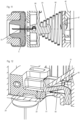
- a second intermediate member 60 ( Figure 13 ) is provided, which is linearly guided by the control element 40 in the needle retraction direction, e.g. by a linear guide 46 provided by the control element 40.
- the linear guide 46 is adapted that the second intermediate member 60 is linearly movable with respect to the control element 40 along the longitudinal axis of the needle 25 or in the needle retraction direction. Furthermore, the linear guide 46 causes the second intermediate member 60 to be moved together with the control element 40 transversely with respect to the needle retraction direction or transversely with respect to the longitudinal axis of the needle 25.
- the second intermediate member 60 When the control element 40 is in its starting position and/or in its insertion release position, the second intermediate member 60 it is engaged with the housing 10, particularly the housing 11, such that the second intermediate member 60 is prevented from being moved in the needle retraction direction ( Figure 13 ).
- the housing 10 comprises a stop surface lib with which the second intermediate member 60 is engaged to prevent the second intermediate member 60 from being moved in the needle retraction direction.
- the second spring member 32 applies a spring force on the second intermediate member 60 in the needle retraction direction.
- the second intermediate member 60 or a counter stop surface 61thereof engages with the needle carrier 20 or a stop surface 23 thereof.
- first intermediate member 50 and the second intermediate member 60 are positioned axially offset from one another particularly in the direction which is transversal with respect to the longitudinal axis of the needle 25 ( Figure 19 ).
- first intermediate member 50 and the second intermediate member 60 are offset from each other in the direction of the longitudinal axis of a needle spike 70.
- the first spring arm 31a rests on a convexly curved contact surface of the first intermediate member 50 as can be seen in Figure 5 .
- the spring arm 31a particularly its circumference surface, moves over the apex of the convexly curved contact surface, thereby the first arm 31a (or its circumference surface) particularly slides and/or rolls over the convexly curved contact surface. This arrangement reduces friction and/or reduces the risk of malfunction with respect to other arrangements.
- Movement of the needle carrier 20 in the needle retraction direction is prevented at least by the remainder of the spring force of the first spring member 31 operating on the first intermediate member 50 as long as the first intermediate member 50 is engaged with the needle carrier 20 ( Figure 6 ).
- the free end of the first spring arm 31a comprises an edge, for example, formed between the circumference surface and the end face of the first spring arm 31a.
- the edge contacts or rests on, particularly -to small or microscopically extent -grooves into, the first intermediate member 50, e.g. on an inclined surface thereof.
- the edge contacting or even grooving into the first intermediate member 50 increases friction between the first intermediate member 50 and the first spring arm 31a.
- the angle between the inclined surface and the circumference surface may, for example, be smaller than the angle between the end face and the circumference surface.
- the second spring arm 32a rests on a convexly curved contact surface of the second intermediate member 60 as can be seen in Figures 13 and 14 . While the second intermediate member 60 is driven by the second spring member 32 in the needle retraction direction, the spring arm 32a moves over the apex of the convexly curved contact surface thereby the second arm 32a particularly slides and/or rolls over the convexly curved contact surface. This arrangement reduces friction and/or reduces the risk of malfunction with respect to other arrangements.
- Movement of the needle carrier 20 back in the needle insertion direction is prevented at least by the remainder of the spring force of the second spring member 32 operating on the second intermediate member 60 as long as the second intermediate member 60 is engaged with the needle carrier 20 ( Figure 14 ).
- the free end of the second spring arm 32a comprises an edge, for example, formed between the circumference surface and the end face of the second spring arm 32a.
- the edge contacts or rests on, particularly-to small or microscopically extent -grooves into, the second intermediate member 60, e.g. on an inclined surface thereof.
- the edge contacting or even grooving into the second intermediate member 60 increases friction between the second intermediate member 60 and the second spring arm 32a.
- the angle between the inclined surface and the circumference surface may, for example, be smaller than the angle between the end face and the circumference surface.
- the spike carrier 80 holds a hollow spike 70 which protrudes from the spike carrier 80 to a receptacle for the product container or to a pierceable wall of the product container, when the product container is inserted in the receptacle ( Figures 8 to 11 ).
- the spike carrier 80 is in a first position in which the spike 70 does not pierce the wall 5 of the product container 4.
- the spike carrier 80 is linearly guided, e.g. by a linear guide provided by the housing 10, preferably by the housing 11, such that the spike carrier 80 can be moved linearly from a first position to a second position together with the spike 70.
- a spring 90 is provided, which operates on the spike carrier 80 to drive the spike carrier 80 from the first position to the second position. In the first position of the spike carrier 80 the spring 90 is in a pre-tensioned condition.
- a variety of spring designs may be conceivable, whereby a conical helical spring 90 is preferred.
- One end of the spring 90 is supported on the spike carrier 80 and the other end of the spring 90 is supported on the housing 10, particularly the housing 11.
- the control element 40 is engaged with the spike carrier 80, when the control element 40 is in its starting position. Thereby, the spike carrier 80 is retained in its first position and the spring 90 is prevented from expanding.
- the control element 40 comprises a retaining surface 47 which engages a counter surface 81to prevent the spike carrier 80 from being moved from the first position to the second position.
- the control element 40 is disengaged from the spike carrier 80, particularly the retaining surface 47 disengages from the counter surface 81 such that the spike carrier 80 is free to be moved from the first position to the second position ( Figure 10 ).
- the spring 90 expands and thereby drives the spike carrier 80 from the first position into the second position ( Figure 11 ).
- the needle insertion and retraction mechanism can be adapted such that the spike carrier 80 is released before, after or at the same time the needle carrier 20 is released to be moved in the needle insertion direction.
- the spike carrier 80 comprises a main body which holds the spike 70 and which is linearly guided by the housing 10.
- the spike may be a hollow steel needle or made from a suitable plastic material.
- a hollow steel needle may be glued into the spike carrier 80.
- the spike carrier 80 comprises a protrusion which protrudes from the main body opposite to the direction in which the spike 70 protrudes.
- the protrusion extends through the (conical) helical spring 90, through a section of the housing 10.
- the section of the housing 10 can be arranged between the section of the control element 40 which comprises the retaining surface 47, and the spike carrier 80.
- the protrusion comprises the counter surface 81.
Landscapes
- Health & Medical Sciences (AREA)
- Heart & Thoracic Surgery (AREA)
- Vascular Medicine (AREA)
- Engineering & Computer Science (AREA)
- Anesthesiology (AREA)
- Biomedical Technology (AREA)
- Hematology (AREA)
- Life Sciences & Earth Sciences (AREA)
- Animal Behavior & Ethology (AREA)
- General Health & Medical Sciences (AREA)
- Public Health (AREA)
- Veterinary Medicine (AREA)
- Dermatology (AREA)
- Infusion, Injection, And Reservoir Apparatuses (AREA)
Applications Claiming Priority (3)
| Application Number | Priority Date | Filing Date | Title |
|---|---|---|---|
| EP18186224.4A EP3603700A1 (de) | 2018-07-30 | 2018-07-30 | Nadeleinführ- und retraktionsmechanismus |
| PCT/IB2019/055544 WO2020026049A1 (en) | 2018-07-30 | 2019-07-01 | Needle insertion and retraction mechanism |
| EP19734921.0A EP3829678B1 (de) | 2018-07-30 | 2019-07-01 | Nadeleinführ- und retraktionsmechanismus |
Related Parent Applications (2)
| Application Number | Title | Priority Date | Filing Date |
|---|---|---|---|
| EP19734921.0A Division EP3829678B1 (de) | 2018-07-30 | 2019-07-01 | Nadeleinführ- und retraktionsmechanismus |
| EP19734921.0A Division-Into EP3829678B1 (de) | 2018-07-30 | 2019-07-01 | Nadeleinführ- und retraktionsmechanismus |
Publications (2)
| Publication Number | Publication Date |
|---|---|
| EP4454682A2 true EP4454682A2 (de) | 2024-10-30 |
| EP4454682A3 EP4454682A3 (de) | 2025-01-22 |
Family
ID=63103783
Family Applications (3)
| Application Number | Title | Priority Date | Filing Date |
|---|---|---|---|
| EP18186224.4A Withdrawn EP3603700A1 (de) | 2018-07-30 | 2018-07-30 | Nadeleinführ- und retraktionsmechanismus |
| EP19734921.0A Active EP3829678B1 (de) | 2018-07-30 | 2019-07-01 | Nadeleinführ- und retraktionsmechanismus |
| EP24194453.7A Pending EP4454682A3 (de) | 2018-07-30 | 2019-07-01 | Nadeleinführ- und retraktionsmechanismus |
Family Applications Before (2)
| Application Number | Title | Priority Date | Filing Date |
|---|---|---|---|
| EP18186224.4A Withdrawn EP3603700A1 (de) | 2018-07-30 | 2018-07-30 | Nadeleinführ- und retraktionsmechanismus |
| EP19734921.0A Active EP3829678B1 (de) | 2018-07-30 | 2019-07-01 | Nadeleinführ- und retraktionsmechanismus |
Country Status (5)
| Country | Link |
|---|---|
| US (1) | US12420010B2 (de) |
| EP (3) | EP3603700A1 (de) |
| JP (1) | JP2021532871A (de) |
| CN (1) | CN112584882B (de) |
| WO (1) | WO2020026049A1 (de) |
Families Citing this family (7)
| Publication number | Priority date | Publication date | Assignee | Title |
|---|---|---|---|---|
| EP3603700A1 (de) | 2018-07-30 | 2020-02-05 | Tecpharma Licensing AG | Nadeleinführ- und retraktionsmechanismus |
| US11554213B2 (en) * | 2018-09-22 | 2023-01-17 | Shl Medical Ag | Injector needle insertion retraction assembly |
| EP3862037A1 (de) | 2020-02-04 | 2021-08-11 | Ypsomed AG | Nadeleinführungsmechanismus für eine injektionsvorrichtung mit verbesserter schlagfestigkeit |
| WO2022104362A1 (en) * | 2020-11-11 | 2022-05-19 | Medtronic Minimed, Inc. | Remotely activated cannula insertion |
| EP4154926A1 (de) | 2021-09-27 | 2023-03-29 | Ypsomed AG | Verbesserter nadeleinführmechanismus für eine injektions- oder infusionsvorrichtung |
| WO2024116017A1 (en) * | 2022-12-01 | 2024-06-06 | Nuova Ompi S.R.L. Unipersonale | Device for subcutaneous delivery of a medicament |
| IT202200024801A1 (it) * | 2022-12-01 | 2024-06-01 | Nuova Ompi S R L Unipersonale | Dispositivo di erogazione sottocutanea di un medicamento |
Citations (9)
| Publication number | Priority date | Publication date | Assignee | Title |
|---|---|---|---|---|
| WO2002040083A2 (en) | 2000-11-09 | 2002-05-23 | Insulet Corporation | Transcutaneous delivery means |
| WO2006108809A1 (en) | 2005-04-13 | 2006-10-19 | Novo Nordisk A/S | Medical skin mountable device and system |
| WO2010029054A1 (en) | 2008-09-10 | 2010-03-18 | F. Hoffmann-La Roche Ag | Delivery device for use with a therapeutic drug |
| WO2011046950A1 (en) | 2009-10-13 | 2011-04-21 | Valeritas, Inc. | Fluid delivery device |
| US20130060233A1 (en) | 2011-09-02 | 2013-03-07 | Unitract Syringe Pty Ltd | Insertion mechanism for a drug delivery pump |
| WO2016053954A1 (en) | 2014-09-29 | 2016-04-07 | Unitract Syringe Pty Ltd | Rigid needle insertion mechanism for a drug delivery pump |
| WO2017219155A1 (en) | 2016-06-23 | 2017-12-28 | Tecpharma Licensing Ag | A needle insertion and retraction mechanism for a medication delivery device |
| GB2552340A (en) | 2016-07-19 | 2018-01-24 | Owen Mumford Ltd | Medicament delivery device |
| WO2018024625A1 (en) | 2016-08-02 | 2018-02-08 | Sanofi-Aventis Deutschland Gmbh | Medicament delivery device |
Family Cites Families (52)
| Publication number | Priority date | Publication date | Assignee | Title |
|---|---|---|---|---|
| DK109293D0 (da) | 1993-09-27 | 1993-09-27 | Novo Nordisk As | Apparat |
| US7621893B2 (en) | 1998-10-29 | 2009-11-24 | Medtronic Minimed, Inc. | Methods and apparatuses for detecting occlusions in an ambulatory infusion pump |
| TW523415B (en) | 2000-03-24 | 2003-03-11 | Novo Nordisk As | A flexible piston rod |
| DE60137034D1 (de) | 2000-05-04 | 2009-01-29 | Novo Nordisk As | Methode zur zusammensetzung einer injektionsvorrichtung mit vormontiertem dosiseinstell- und injektionsmechanismus |
| DK1583573T3 (da) | 2002-12-23 | 2011-05-09 | Asante Solutions Inc | Bøjelig stempelstang |
| EP1646412B1 (de) | 2003-07-08 | 2007-03-28 | Novo Nordisk A/S | Tragbares medikamentenabgabegerät mit einer eingekapselten nadel |
| DE102004059491B4 (de) | 2004-12-10 | 2008-11-06 | Roche Diagnostics Gmbh | Lanzettenvorrichtung zum Erzeugen einer Einstichwunde und Lanzettenantriebs-Baugruppe |
| US8167841B2 (en) * | 2005-01-24 | 2012-05-01 | Novo Nordisk A/S | Transcutaneous device assembly |
| US7794427B2 (en) | 2005-09-26 | 2010-09-14 | Asante Solutions, Inc. | Operating an infusion pump system |
| US7682338B2 (en) * | 2006-08-23 | 2010-03-23 | Medtronic Minimed, Inc. | Infusion medium delivery system, device and method with needle inserter and needle inserter device and method |
| US8449505B2 (en) | 2006-11-17 | 2013-05-28 | Bencha International Group Inc. | Automatically retractable medically safety injector and plunger combination thereof |
| JP2010517700A (ja) * | 2007-02-09 | 2010-05-27 | デカ・プロダクツ・リミテッド・パートナーシップ | 自動挿入アセンブリ |
| US20090093793A1 (en) | 2007-10-02 | 2009-04-09 | Yossi Gross | External drug pump |
| DE102007049446A1 (de) * | 2007-10-16 | 2009-04-23 | Cequr Aps | Katheter-Einführeinrichtung |
| US9393369B2 (en) | 2008-09-15 | 2016-07-19 | Medimop Medical Projects Ltd. | Stabilized pen injector |
| EP2440267B1 (de) | 2009-06-10 | 2018-10-24 | Fresenius Kabi Deutschland GmbH | Portkanüle mit nadelstichschutzvorrichtung |
| WO2011012465A1 (en) | 2009-07-30 | 2011-02-03 | Unomedical A/S | Inserter device with horizontal moving part |
| US8157769B2 (en) | 2009-09-15 | 2012-04-17 | Medimop Medical Projects Ltd. | Cartridge insertion assembly for drug delivery system |
| US8236168B2 (en) | 2009-10-13 | 2012-08-07 | Exxonmobil Research And Engineering Company | Onset haze measurement apparatus and procedure |
| CA2779793C (en) | 2009-11-03 | 2014-04-08 | F. Hoffmann-La Roche Ag | Device for almost germ-free provision of a fluid medium |
| ATE553800T1 (de) * | 2009-11-26 | 2012-05-15 | Hoffmann La Roche | Extern auslösbare kanülenanordnung |
| CN110548195B (zh) | 2010-06-09 | 2022-05-13 | 西兰制药公司 | 流体输送装置针收回机构、筒及可扩张液压流体密封件 |
| EP2438942A1 (de) * | 2010-10-08 | 2012-04-11 | Sanofi-Aventis Deutschland GmbH | Automatischer Injektor |
| BR112014005482A2 (pt) | 2011-09-13 | 2017-04-04 | Unitract Syringe Pty Ltd | conexão de via de passagem de fluido estéril a recipientes de fármacos para bombas de administração de fármaco |
| US9724462B2 (en) | 2012-03-19 | 2017-08-08 | Steadymed Ltd. | Fluid-connection mechanism for patch-pumps |
| EP2712650A1 (de) | 2012-09-27 | 2014-04-02 | F. Hoffmann-La Roche AG | Adapter und Arzneimittelkartuschenausrichtungsvorrichtung |
| ES2741017T3 (es) * | 2013-05-31 | 2020-02-07 | Valeritas Inc | Un dispositivo de suministro de fluido que tiene un cartucho precargado insertable |
| EP2832390A1 (de) * | 2013-07-30 | 2015-02-04 | Sensile Pat AG | Arzneimittelabgabevorrichtung mit Nadelbetätigungsmechanismus |
| US10173001B2 (en) | 2013-09-05 | 2019-01-08 | Sanofi-Aventis Deutschland | Drive mechanism for a needle insertion arrangement |
| JP6476188B2 (ja) * | 2013-09-05 | 2019-02-27 | サノフィ−アベンティス・ドイチュラント・ゲゼルシャフト・ミット・ベシュレンクテル・ハフツング | 手動でトリガされ、ばね荷重される駆動機構を有する針挿入および後退配置 |
| US10369345B2 (en) * | 2014-03-31 | 2019-08-06 | Versago Vascular Access, Inc. | Medical access port, systems and methods of use thereof |
| JP6752719B2 (ja) * | 2014-04-24 | 2020-09-09 | ベクトン・ディキンソン・アンド・カンパニーBecton, Dickinson And Company | カテーテル挿入装置 |
| EP3834863A1 (de) | 2015-03-02 | 2021-06-16 | Amgen, Inc | Vorrichtung und verfahren zur errichtung aseptischer verbindungen |
| US10251813B2 (en) | 2015-03-04 | 2019-04-09 | West Pharma. Services IL, Ltd. | Flexibly mounted cartridge alignment collar for drug delivery device |
| US9795534B2 (en) | 2015-03-04 | 2017-10-24 | Medimop Medical Projects Ltd. | Compliant coupling assembly for cartridge coupling of a drug delivery device |
| DK3380149T3 (da) | 2015-11-27 | 2020-02-03 | Sanofi Aventis Deutschland | Lægemiddeladministrationsanordning med en hætte |
| US9907904B2 (en) * | 2016-05-10 | 2018-03-06 | Burton H. Sage, Jr. | Spring-driven drug delivery device |
| EP3871708A3 (de) * | 2016-05-26 | 2022-01-19 | Insulet Corporation | Tragbares medikamentenverabreichungssystem mit vorgefüllter kartusche |
| US10792432B2 (en) | 2016-06-09 | 2020-10-06 | Becton, Dickinson And Company | Drive assembly and spacer for drug delivery system |
| EP3260149A1 (de) | 2016-06-23 | 2017-12-27 | TecPharma Licensing AG | Verfahren zur befestigung einer kartusche in einer einspritzvorrichtung |
| EP3348284A2 (de) | 2017-01-12 | 2018-07-18 | Tecpharma Licensing AG | Verfahren zur sterilisierung eines fluidpfads für eine injektionsvorrichtung |
| EP3260146A1 (de) | 2016-06-23 | 2017-12-27 | TecPharma Licensing AG | Kupplungsmechanismus für eine medikamentenausgabevorrichtung |
| WO2018080959A1 (en) * | 2016-10-31 | 2018-05-03 | Summit Street Medical LLC | Wearable drug delivery device |
| MX2019009755A (es) * | 2017-02-17 | 2019-10-07 | Amgen Inc | Mecanismo de insercion para dispositivo de suministro de farmacos. |
| WO2018156548A1 (en) | 2017-02-22 | 2018-08-30 | Insulet Corporation | Needle insertion mechanisms for drug containers |
| US10792425B2 (en) * | 2017-03-03 | 2020-10-06 | Jerry Joseph | Treatment system with automated cannula and sensor inserter, fluid delivery device, and drive mechanism for use therewith |
| IL268386B2 (en) | 2017-03-09 | 2023-11-01 | Amgen Inc | Insertion mechanism for a drug delivery device |
| EP3656419A1 (de) | 2018-11-22 | 2020-05-27 | Tecpharma Licensing AG | Anordnung für einen kartuschennadeleinführmechanismus |
| WO2021083746A1 (en) | 2019-10-31 | 2021-05-06 | Ypsomed Ag | An assembly for a cartridge needle insertion mechanism |
| EP3539592A1 (de) | 2018-03-15 | 2019-09-18 | Tecpharma Licensing AG | Injektions- oder infusionsvorrichtung mit einem verbesserten gehäuse und trennschicht zur beseitigung von sterilen barrierefolien unter verwendung der trennschicht |
| EP3603700A1 (de) | 2018-07-30 | 2020-02-05 | Tecpharma Licensing AG | Nadeleinführ- und retraktionsmechanismus |
| EP3862037A1 (de) * | 2020-02-04 | 2021-08-11 | Ypsomed AG | Nadeleinführungsmechanismus für eine injektionsvorrichtung mit verbesserter schlagfestigkeit |
-
2018
- 2018-07-30 EP EP18186224.4A patent/EP3603700A1/de not_active Withdrawn
-
2019
- 2019-07-01 JP JP2021505191A patent/JP2021532871A/ja not_active Ceased
- 2019-07-01 EP EP19734921.0A patent/EP3829678B1/de active Active
- 2019-07-01 WO PCT/IB2019/055544 patent/WO2020026049A1/en not_active Ceased
- 2019-07-01 CN CN201980050943.6A patent/CN112584882B/zh active Active
- 2019-07-01 EP EP24194453.7A patent/EP4454682A3/de active Pending
-
2021
- 2021-01-14 US US17/149,347 patent/US12420010B2/en active Active
Patent Citations (9)
| Publication number | Priority date | Publication date | Assignee | Title |
|---|---|---|---|---|
| WO2002040083A2 (en) | 2000-11-09 | 2002-05-23 | Insulet Corporation | Transcutaneous delivery means |
| WO2006108809A1 (en) | 2005-04-13 | 2006-10-19 | Novo Nordisk A/S | Medical skin mountable device and system |
| WO2010029054A1 (en) | 2008-09-10 | 2010-03-18 | F. Hoffmann-La Roche Ag | Delivery device for use with a therapeutic drug |
| WO2011046950A1 (en) | 2009-10-13 | 2011-04-21 | Valeritas, Inc. | Fluid delivery device |
| US20130060233A1 (en) | 2011-09-02 | 2013-03-07 | Unitract Syringe Pty Ltd | Insertion mechanism for a drug delivery pump |
| WO2016053954A1 (en) | 2014-09-29 | 2016-04-07 | Unitract Syringe Pty Ltd | Rigid needle insertion mechanism for a drug delivery pump |
| WO2017219155A1 (en) | 2016-06-23 | 2017-12-28 | Tecpharma Licensing Ag | A needle insertion and retraction mechanism for a medication delivery device |
| GB2552340A (en) | 2016-07-19 | 2018-01-24 | Owen Mumford Ltd | Medicament delivery device |
| WO2018024625A1 (en) | 2016-08-02 | 2018-02-08 | Sanofi-Aventis Deutschland Gmbh | Medicament delivery device |
Also Published As
| Publication number | Publication date |
|---|---|
| CN112584882A (zh) | 2021-03-30 |
| US20210138151A1 (en) | 2021-05-13 |
| EP4454682A3 (de) | 2025-01-22 |
| US12420010B2 (en) | 2025-09-23 |
| CN112584882B (zh) | 2022-10-21 |
| WO2020026049A1 (en) | 2020-02-06 |
| EP3829678B1 (de) | 2024-09-25 |
| EP3603700A1 (de) | 2020-02-05 |
| EP3829678A1 (de) | 2021-06-09 |
| JP2021532871A (ja) | 2021-12-02 |
Similar Documents
| Publication | Publication Date | Title |
|---|---|---|
| EP3829678B1 (de) | Nadeleinführ- und retraktionsmechanismus | |
| US11504481B2 (en) | Anti-rotation feature for infusion pump cartridge | |
| EP2569031B1 (de) | Genauer injektor für geringe volumen | |
| CN103167887B (zh) | 医用注射装置 | |
| EP3862037A1 (de) | Nadeleinführungsmechanismus für eine injektionsvorrichtung mit verbesserter schlagfestigkeit | |
| JP2009538693A (ja) | 使い捨て注入装置のためのカニューレ送出器具及び方法 | |
| WO2013079652A9 (en) | Drug filled delivery assembly | |
| JP2017515540A (ja) | カテーテル挿入デバイス | |
| EP3501576A1 (de) | Nadeleinführungs- und -rückziehmechanismus für eine medikamentenverabreichungsvorrichtung | |
| EP4051339B1 (de) | Anordnung für einen kartuschennadeleinführmechanismus | |
| EP3656419A1 (de) | Anordnung für einen kartuschennadeleinführmechanismus | |
| JP2022516494A (ja) | 物質の分離保管のための薬剤貯蔵部 | |
| EP4487887A1 (de) | Antriebsfeder und nadelabdeckfeder für eine injektionsvorrichtung | |
| CN104136055B (zh) | 药物输送帮浦用与药物容器连接的无菌液体沟道连接件 |
Legal Events
| Date | Code | Title | Description |
|---|---|---|---|
| PUAI | Public reference made under article 153(3) epc to a published international application that has entered the european phase |
Free format text: ORIGINAL CODE: 0009012 |
|
| STAA | Information on the status of an ep patent application or granted ep patent |
Free format text: STATUS: THE APPLICATION HAS BEEN PUBLISHED |
|
| AC | Divisional application: reference to earlier application |
Ref document number: 3829678 Country of ref document: EP Kind code of ref document: P |
|
| AK | Designated contracting states |
Kind code of ref document: A2 Designated state(s): AL AT BE BG CH CY CZ DE DK EE ES FI FR GB GR HR HU IE IS IT LI LT LU LV MC MK MT NL NO PL PT RO RS SE SI SK SM TR |
|
| PUAL | Search report despatched |
Free format text: ORIGINAL CODE: 0009013 |
|
| AK | Designated contracting states |
Kind code of ref document: A3 Designated state(s): AL AT BE BG CH CY CZ DE DK EE ES FI FR GB GR HR HU IE IS IT LI LT LU LV MC MK MT NL NO PL PT RO RS SE SI SK SM TR |
|
| RIC1 | Information provided on ipc code assigned before grant |
Ipc: A61M 5/158 20060101AFI20241218BHEP |
|
| STAA | Information on the status of an ep patent application or granted ep patent |
Free format text: STATUS: REQUEST FOR EXAMINATION WAS MADE |
|
| 17P | Request for examination filed |
Effective date: 20250722 |