EP4454476A1 - Cooling system and machine for the production of ice creams comprising such system - Google Patents
Cooling system and machine for the production of ice creams comprising such system Download PDFInfo
- Publication number
- EP4454476A1 EP4454476A1 EP24171706.5A EP24171706A EP4454476A1 EP 4454476 A1 EP4454476 A1 EP 4454476A1 EP 24171706 A EP24171706 A EP 24171706A EP 4454476 A1 EP4454476 A1 EP 4454476A1
- Authority
- EP
- European Patent Office
- Prior art keywords
- peltier cells
- belt element
- cooling system
- central body
- iii
- Prior art date
- Legal status (The legal status is an assumption and is not a legal conclusion. Google has not performed a legal analysis and makes no representation as to the accuracy of the status listed.)
- Pending
Links
Images



Classifications
-
- F—MECHANICAL ENGINEERING; LIGHTING; HEATING; WEAPONS; BLASTING
- F25—REFRIGERATION OR COOLING; COMBINED HEATING AND REFRIGERATION SYSTEMS; HEAT PUMP SYSTEMS; MANUFACTURE OR STORAGE OF ICE; LIQUEFACTION SOLIDIFICATION OF GASES
- F25B—REFRIGERATION MACHINES, PLANTS OR SYSTEMS; COMBINED HEATING AND REFRIGERATION SYSTEMS; HEAT PUMP SYSTEMS
- F25B21/00—Machines, plants or systems, using electric or magnetic effects
- F25B21/02—Machines, plants or systems, using electric or magnetic effects using Peltier effect; using Nernst-Ettinghausen effect
-
- A—HUMAN NECESSITIES
- A23—FOODS OR FOODSTUFFS; TREATMENT THEREOF, NOT COVERED BY OTHER CLASSES
- A23G—COCOA; COCOA PRODUCTS, e.g. CHOCOLATE; SUBSTITUTES FOR COCOA OR COCOA PRODUCTS; CONFECTIONERY; CHEWING GUM; ICE-CREAM; PREPARATION THEREOF
- A23G9/00—Frozen sweets, e.g. ice confectionery, ice-cream; Mixtures therefor
- A23G9/04—Production of frozen sweets, e.g. ice-cream
-
- A—HUMAN NECESSITIES
- A23—FOODS OR FOODSTUFFS; TREATMENT THEREOF, NOT COVERED BY OTHER CLASSES
- A23G—COCOA; COCOA PRODUCTS, e.g. CHOCOLATE; SUBSTITUTES FOR COCOA OR COCOA PRODUCTS; CONFECTIONERY; CHEWING GUM; ICE-CREAM; PREPARATION THEREOF
- A23G9/00—Frozen sweets, e.g. ice confectionery, ice-cream; Mixtures therefor
- A23G9/04—Production of frozen sweets, e.g. ice-cream
- A23G9/22—Details, component parts or accessories of apparatus insofar as not peculiar to a single one of the preceding groups
-
- A—HUMAN NECESSITIES
- A23—FOODS OR FOODSTUFFS; TREATMENT THEREOF, NOT COVERED BY OTHER CLASSES
- A23G—COCOA; COCOA PRODUCTS, e.g. CHOCOLATE; SUBSTITUTES FOR COCOA OR COCOA PRODUCTS; CONFECTIONERY; CHEWING GUM; ICE-CREAM; PREPARATION THEREOF
- A23G9/00—Frozen sweets, e.g. ice confectionery, ice-cream; Mixtures therefor
- A23G9/04—Production of frozen sweets, e.g. ice-cream
- A23G9/08—Batch production
-
- A—HUMAN NECESSITIES
- A23—FOODS OR FOODSTUFFS; TREATMENT THEREOF, NOT COVERED BY OTHER CLASSES
- A23G—COCOA; COCOA PRODUCTS, e.g. CHOCOLATE; SUBSTITUTES FOR COCOA OR COCOA PRODUCTS; CONFECTIONERY; CHEWING GUM; ICE-CREAM; PREPARATION THEREOF
- A23G9/00—Frozen sweets, e.g. ice confectionery, ice-cream; Mixtures therefor
- A23G9/04—Production of frozen sweets, e.g. ice-cream
- A23G9/08—Batch production
- A23G9/12—Batch production using means for stirring the contents in a non-moving container
-
- A—HUMAN NECESSITIES
- A23—FOODS OR FOODSTUFFS; TREATMENT THEREOF, NOT COVERED BY OTHER CLASSES
- A23G—COCOA; COCOA PRODUCTS, e.g. CHOCOLATE; SUBSTITUTES FOR COCOA OR COCOA PRODUCTS; CONFECTIONERY; CHEWING GUM; ICE-CREAM; PREPARATION THEREOF
- A23G9/00—Frozen sweets, e.g. ice confectionery, ice-cream; Mixtures therefor
- A23G9/04—Production of frozen sweets, e.g. ice-cream
- A23G9/22—Details, component parts or accessories of apparatus insofar as not peculiar to a single one of the preceding groups
- A23G9/222—Freezing drums
-
- A—HUMAN NECESSITIES
- A23—FOODS OR FOODSTUFFS; TREATMENT THEREOF, NOT COVERED BY OTHER CLASSES
- A23G—COCOA; COCOA PRODUCTS, e.g. CHOCOLATE; SUBSTITUTES FOR COCOA OR COCOA PRODUCTS; CONFECTIONERY; CHEWING GUM; ICE-CREAM; PREPARATION THEREOF
- A23G9/00—Frozen sweets, e.g. ice confectionery, ice-cream; Mixtures therefor
- A23G9/04—Production of frozen sweets, e.g. ice-cream
- A23G9/22—Details, component parts or accessories of apparatus insofar as not peculiar to a single one of the preceding groups
- A23G9/224—Agitators or scrapers
-
- A—HUMAN NECESSITIES
- A23—FOODS OR FOODSTUFFS; TREATMENT THEREOF, NOT COVERED BY OTHER CLASSES
- A23G—COCOA; COCOA PRODUCTS, e.g. CHOCOLATE; SUBSTITUTES FOR COCOA OR COCOA PRODUCTS; CONFECTIONERY; CHEWING GUM; ICE-CREAM; PREPARATION THEREOF
- A23G9/00—Frozen sweets, e.g. ice confectionery, ice-cream; Mixtures therefor
- A23G9/04—Production of frozen sweets, e.g. ice-cream
- A23G9/22—Details, component parts or accessories of apparatus insofar as not peculiar to a single one of the preceding groups
- A23G9/225—Ice-cream freezing and storing cabinets
-
- F—MECHANICAL ENGINEERING; LIGHTING; HEATING; WEAPONS; BLASTING
- F25—REFRIGERATION OR COOLING; COMBINED HEATING AND REFRIGERATION SYSTEMS; HEAT PUMP SYSTEMS; MANUFACTURE OR STORAGE OF ICE; LIQUEFACTION SOLIDIFICATION OF GASES
- F25B—REFRIGERATION MACHINES, PLANTS OR SYSTEMS; COMBINED HEATING AND REFRIGERATION SYSTEMS; HEAT PUMP SYSTEMS
- F25B1/00—Compression machines, plants or systems with non-reversible cycle
Definitions
- the present invention refers to a cooling system to be applied to machines, particularly in machines for food products or pharmaceutical/cosmetic/chemical products, even more particularly for the domestic production of food, for example a machine for producing single portions of ice cream, mousse, sorbets, creams, or still other food.
- the invention also relates to a machine, particularly a machine for food use, provided with such cooling system.
- a cooling system particularly adapted to be applied to machines for producing single portions of ice cream, sorbet, mousse, or other cold food creams is known from Italian Patent Application No. IT102020000024817 .
- Such cooling system is extremely effective and capable of cooling in a homogeneous and almost immediate manner (maximum cooling rate higher than 1 °C/sec) the ice cream being prepared or other food mixture, avoiding the creation of ice blocks and clumps, thus allowing single portions of ice cream to be prepared almost instantaneously and on demand.
- Such cooling system is further compact, space-saving, extremely effective, and eco-friendly since it does not use refrigerant gases nor requires the cold chain.
- the cooling system described in Patent Application No. IT102020000024817 comprises four Peltier cells 2 fixed on the external flanks of a central body made of aluminium 1 - which forms the receptacle in which the ice cream is creamed - through two elements made of steel wire 51 and two respective tensioning metallic bars 52.
- Each element made of steel wire 51 is approximately U- or C-shaped and its threaded ends pass through two holes formed on a respective bar 52.
- thermoelectric modules - referred to as "Peltier cells" in the present description - 2 located in positions diametrically opposite to each other ( figures 1 , 2 of Application No. IT102020000024817 ).
- an assembly formed by a steel wire 51 and the relative bar 52 is capable of pushing against the main body 1 exactly two Peltier cells, not a different number.
- Such maximum number is also limited, in reality, by the bulk of the different bars 52 as well as the rapid increase of the mounting time and the production costs of the known cooling system 50 as a function of the increasing number of pairs of wire 51 + bar 52 mounted on the flanks of a main body 1.
- an object of the present invention is to provide a cooling system for producing ice cream or other alimentary pastes or more generally for processing a mixture, which allows to also fix a greater number, also odd, of Peltier cells on the flanks of a central body 1 in a mechanically easier, cheaper, quicker, and more efficient manner.
- a further object of the present invention is to make a machine, particularly a machine for food use as set forth in claim 13.
- a cooling system overall indicated by 10', 10", 10 III , is shown, particularly for use in a machine (not shown in the attached figures) for processing, thus cooling, a mixture, such as for example a food mixture for the production of ice cream.
- the cooling system 10', 10", 10 III comprises a central body 1', 1", 1 III which in turn comprises a working cavity 100 suitable for housing the mixture and/or the products to be cooled, directly or through a further container.
- the working cavity 100 defines an axis AXC which is the rotation axis around which a possible rotor - for example one or more blades or scrapers of a creaming machine - arranged in the cavity 100 rotates, and/or is the symmetrical axis of the cavity 100 if it has a substantially cylindrical or prismatic shape and/or the axis of the cone, truncated cone, pyramid, or truncated pyramid possibly formed by the working cavity 100 ( figure 1 ).
- the central body 1', 1", 1 III preferably forms external flanks extending substantially parallel or longitudinal to the axis AXC of the working cavity 100.
- the central body 1', 1", 1 III is preferably made of a material having a high thermal conductivity such as for example aluminium, copper, steel, or other metallic material.
- the system 10' can comprise three or more Peltier cells 2 arranged laterally to the central body 1', 1", 1 III and directly contacting the central body 1', 1", 1 III itself.
- each Peltier cell 2 has an overall flat shape so as to form two greater faces each of which facing a direction of the space substantially opposite to that the other plate faces.
- each Peltier cell 2 can have a substantially plate shape, preferably flat ( figures 1- 6 ) .
- the Peltier cells 2 are arranged so as to have one of the greater faces contacting the central body 1', 1", 1 III , so as to promote the heat transmission to and from the body 1'.
- the central body 1', 1", 1 III preferably forms one or more coupling faces 11 configured for coupling with a respective greater face of a Peltier cell 2, particularly with the cold face of such cell; for this purpose, each coupling face 11 can have a substantially flat shape, or otherwise substantially complementary to - or having the cast of - the greater face of the Peltier cell 2.
- the one or more coupling faces 11 is preferably formed on the external flanks of the central body 1', 1", 1 III ( figure 9 ) .
- the cooling system 10' preferably comprises one or more heat sinks 3 for example in a number corresponding to the number of Peltier cells 2 and suitable for keeping the temperature of the same under control during the steps of cooling the food mixture.
- the cooling system 10' can comprise a variable number of Peltier cells 2 depending on the requirements, therefore on the required cooling power, which can be arranged both laterally to and below the central body 1', 1", 1 III .
- the cooling system 10' comprises at least three Peltier cells 2 and accordingly a corresponding number of heat sinks 3 associated to each Peltier cell ( figures 1 , 2 ).
- the cooling system 10' can possibly comprise even at least four Peltier cells 2 ( figures 3 , 4 ), at least five Peltier cells 2 ( figures 5 , 6 ), at least six Peltier cells 2, at least seven Peltier cells 2, at least eight Peltier cells 2, and for example three, four, five, six, seven, eight, nine, ten, or more Peltier cells 2 each of which arranged for example on the external flanks of the central body 1', 1", 1 III .
- the cooling system 10' further comprises an assembling system 5' which keeps the central body 1', 1", 1 III , the three or more Peltier cells 2 and the corresponding three or more cooling subunits 3 assembled.
- the assembling system 5' in turn comprises a belt element 51 and a tensioner 55.
- the belt element 51 extends around the at least three Peltier cells 2 and the relative heat sinks 3.
- the tensioner 55 is configured for tensioning the belt element 51 by reducing or tending to reduce the perimeter of the portion of the belt element 51 extending around the at least three Peltier cells 2 and the one or more possible heat sinks 3 so as to tighten the at least three Peltier cells 2 against the external flanks of the central body 1', 1", 1 III and fix the at least three Peltier cells 2 to said external flanks.
- the tensioner 55 is configured for tensioning the belt element 51 so as to approach or tend to approach each other at least two proximity sections 510, 512 of the belt element 51 - for example two single proximity sections 510, 512 - adjacent to the tensioner 55 - for example the closest to the tensioner 55 - so as to tighten the at least three Peltier cells 2 against the external flanks of the central body 1', 1", 1 III and fix the at least three Peltier cells 2 to said external flanks.
- the belt element 51 can comprise for example a wire ( figures 1-6 ), a band or strip, a chain, a membrane, a coil spring; preferably, such elements can be made for example of steel or other metallic material but can be also made of a synthetic resin or other non-metallic materials.
- the belt element 51 is preferably coated by a layer of anti-corrosion material.
- the tensioner 55 can comprise for example a screw drive configured for approaching each other the two proximity sections 510, 512 of the belt element 51, for example by pulling or pushing the two proximity sections 510, 512 so as to slide them in directions substantially parallel or longitudinal to the sections 510, 512 themselves by reducing the perimeter of the belt element 51.
- the tensioner 55 can comprise for example a screw 514 configured for screwing and unscrewing in a nut screw by rotating around an axis substantially parallel or longitudinal to the two proximity sections 510, 512 ( figures 1 , 3, 5 ).
- the tensioner 55 can comprise for example a cam, lever, or inclined plane system and be driven thereby.
- the screw 514 or other screw or a screw, cam, lever, or inclined plane drive of the tensioner 55 can be configured for tensioning the belt element 51 by reducing or tending to reduce the perimeter of the portion of the belt element 51 extending around the at least three Peltier cells 2 and the one or more possible heat sinks 3 so as to tighten the at least three Peltier cells 2 against the external flanks of the central body 1', 1", 1 III and fix the at least three Peltier cells 2 to said external flanks.
- a single screw 514 or another single screw, a single screw drive, a single cam, a single lever, or a single inclined plane can be configured for tensioning the belt element 51 by reducing or tending to reduce the perimeter of the portion of the belt element 51 extending around the at least three Peltier cells 2 and the one or more possible heat sinks 3 so as to tighten the at least three Peltier cells 2 against the external flanks of the central body 1', 1", 1 III and fix the at least three Peltier cells 2 to said external flanks.
- the assembling system 5' comprises a single belt element 51 and/or a single tensioner 55.
- each tensioner 55 is configured for tensioning a single belt element 51 so as to reduce or tend to reduce the perimeter of the portion of the belt element 51 extending around all the three of the at least three Peltier cells 2 and the one or more possible heat sinks 3, by tightening the at least three Peltier cells 2 against the external flanks of the central body 1', 1", 1 III and fixing the at least three Peltier cells 2 to said external flanks.
- the assembling system 5' further comprises one or more mechanical adapters 57 each of which is interposed between the belt element 51 and one or more heat sinks 3 or otherwise one or more Peltier cells 2 so as to transmit to such cells 2 and possibly to the sinks 3 the thrust applied by the belt element 51 towards the working cavity 100 and/or towards the centre of the central body 1', 1", 1 III .
- Each mechanical adapter 57 can be made for example like a bearing or pad preferably made of a relatively rigid and slick material such as for example polyoxymethylene (POM or acetal resin), polyamide (PA), or polytetrafluoroethylene (Teflon (R)) so as to reduce the friction with the belt element 51.
- a relatively rigid and slick material such as for example polyoxymethylene (POM or acetal resin), polyamide (PA), or polytetrafluoroethylene (Teflon (R)
- a reduced friction between the mechanical adapters 57 and the belt element 51 makes the tangential forces applied by the latter to the adapters 57 when it is tightened - o otherwise tensioned - and accordingly applied by the adapters 57 to the Peltier cells 2 negligible, improving the adherence and the contact of the adapters against the cells 2 and therefore the performance of the latter.
- each of them preferably forms one or more ribs, corrugations, studs or other protrusions 570 on its face - or other surface - which rests against the belt element 51 or in any case faces it so as to reduce the surface contacting the belt element 51 ( figures 1 , 3, 5 ).
- the pressure between the Peltier cells 2 and the central body 1', 1", 1 III is very important in order to keep the efficiency of the cooling system 10', 10", 10 III high, while the pressure between the Peltier cells 2 and the heat sinks 3 is very important for the good operation of the Peltier cells 2 themselves, preventing them from overheating.
- the cooling system 10', 10", 10 III further comprises a base element 4 made of a thermal insulating material suitable for acting as a base and meanwhile as a mounting mask for the cooling system 10 itself on the machine in which it is used.
- the heat sinks 3 can be of the liquid type and be fluidically or otherwise functionally connected to a cooling circuit 30, illustrated in figure 7 , comprising at least a radiator 31, a tank 32, and to a pump 33 for recirculating the cooling liquid and comprise at least an inlet piping and an outlet piping of the cooling liquid preferably made of copper.
- each heat sink 3 the heat carrier liquid goes in and out through a respective inlet and outlet piping.
- the cooling liquid can be water or any other type of cooling liquid.
- Figure 7 illustrates a possible embodiment of the cooling circuit 30 inside a machine.
- Peltier cells 2 can be powered for example at 15 V by an electrical energy source arranged for example in the machine.
- Each Peltier cell 2 as illustrated in figure 10 , preferably comprises a shell of two ceramic plates which sandwich semiconductors which, passed through by direct current, cool one of the two plates and heat the other.
- the ceramic plate facing the central body 1', 1", 1 III will be cooled, thus cooling the content of the central body 1', 1", 1 III itself, while the ceramic plate facing the opposite side will be heated in a controlled manner due to the heat sinks 3 associated to each Peltier cell 2.
- the Peltier cells 2 can be used to heat the ceramic plate facing the central body 1', 1", 1 III , thus heating the content of the central body 1', 1", 1 III itself, and instead cooling the ceramic plate facing the opposite side; in such case the heat sinks 3 are preferably deactivated, if they are active and not only passive components.
- the base element 2 is made of synthetic resin.
- the operation of the cooling system is as follows.
- the mixture of ingredients to be cooled is inserted into the working cavity 100 and the machine, particularly its cooling system 10', 10", 10 III , are activated.
- the semiconductors present in the Peltier cells 2 are passed through by a direct current, provided by the power supply present in the machine, which causes a side of them to be cooled, particularly that contacting the central body 1', 1", 1 III , and the opposite side to be heated.
- the heat sinks 3 are activated, which due to the cooling circuit 30 are passed through by a cooling liquid suitable for keeping the temperature of the side of the Peltier cells 2 facing them under control.
- Such system allows to obtain the freezing of the mixture inside the central body in about 180 seconds.
- each wire, band, strip, chain, or membrane pertaining to the belt element 51 and for example forming it can be wound around the at least three Peltier cells 2, so as to tighten them, forming one or more turns.
- the used materials, as well as the size can be any depending on the technical requirements.
Landscapes
- Engineering & Computer Science (AREA)
- Life Sciences & Earth Sciences (AREA)
- Chemical & Material Sciences (AREA)
- Food Science & Technology (AREA)
- Polymers & Plastics (AREA)
- Physics & Mathematics (AREA)
- Mechanical Engineering (AREA)
- Thermal Sciences (AREA)
- General Engineering & Computer Science (AREA)
- Manufacturing & Machinery (AREA)
- Devices That Are Associated With Refrigeration Equipment (AREA)
- Confectionery (AREA)
Abstract
Description
- The present invention refers to a cooling system to be applied to machines, particularly in machines for food products or pharmaceutical/cosmetic/chemical products, even more particularly for the domestic production of food, for example a machine for producing single portions of ice cream, mousse, sorbets, creams, or still other food.
- The invention also relates to a machine, particularly a machine for food use, provided with such cooling system.
- The following description specifically refers to food machines, particularly for the production of ice cream, however, the Applicant specifies that such cooling system is not intended to be limited to the use in food machines but can be applied for cooling any type of cream or product.
- A cooling system particularly adapted to be applied to machines for producing single portions of ice cream, sorbet, mousse, or other cold food creams is known from Italian Patent Application No.
IT102020000024817 - Such cooling system is extremely effective and capable of cooling in a homogeneous and almost immediate manner (maximum cooling rate higher than 1°C/sec) the ice cream being prepared or other food mixture, avoiding the creation of ice blocks and clumps, thus allowing single portions of ice cream to be prepared almost instantaneously and on demand.
- Such cooling system is further compact, space-saving, extremely effective, and eco-friendly since it does not use refrigerant gases nor requires the cold chain.
- The cooling system described in Patent Application No.
IT102020000024817 Peltier cells 2 fixed on the external flanks of a central body made of aluminium 1 - which forms the receptacle in which the ice cream is creamed - through two elements made ofsteel wire 51 and two respective tensioning metallic bars 52. - Each element made of
steel wire 51 is approximately U- or C-shaped and its threaded ends pass through two holes formed on a respective bar 52. - By screwing them on such threaded ends, two respective threaded nuts 53 rest against the external face of the bar 52 and push it towards the bottom of the cavity formed by the steel wire 51 (
figure 5 of Application No.IT102020000024817 central body 1 two thermoelectric modules - referred to as "Peltier cells" in the present description - 2 located in positions diametrically opposite to each other (figures 1 ,2 of Application No.IT102020000024817 - The author of the present invention observed that such known fixing system allows only an even number of
Peltier cells 2 to be mounted on the external flanks of thecentral body 1, and in the practice allows only two or fourPeltier cells 2 to be mounted, actually making mounting for example six, eight, or a greater even number of them impossible or very disadvantageous. - Indeed, an assembly formed by a
steel wire 51 and the relative bar 52 is capable of pushing against themain body 1 exactly two Peltier cells, not a different number. - In order to fix to the
main body 1 multiple pairs ofPeltier cells 2, the same number ofsteel wires 51 are to be mounted, inevitably overlapping each other in the direction of the central axis of themain body 1 itself. - As the number of overlapping
wires 51 increases, somePeltier cells 2, due to the bulk of the various components, are pressed by therespective wire 51 in positions increasingly closer to the lower or upper edge of the cells themselves, causing undesired concentrations of pressure on the flanks of thecentral body 1 and by fixing the Peltier cells increasingly less firmly, and therefore limiting the maximum number to only four Peltier cells which in the practice can be mounted in a knowncooling system 10 described in Application No.IT102020000024817 - Such maximum number is also limited, in reality, by the bulk of the different bars 52 as well as the rapid increase of the mounting time and the production costs of the known cooling system 50 as a function of the increasing number of pairs of
wire 51 + bar 52 mounted on the flanks of amain body 1. - Therefore, an object of the present invention is to provide a cooling system for producing ice cream or other alimentary pastes or more generally for processing a mixture, which allows to also fix a greater number, also odd, of Peltier cells on the flanks of a
central body 1 in a mechanically easier, cheaper, quicker, and more efficient manner. - These and other objects according to the present invention are achieved by making a cooling system as set forth in
claim 1. - Further features of the system are the object of the dependent claims.
- A further object of the present invention is to make a machine, particularly a machine for food use as set forth in claim 13.
- The features and the advantages of a cooling system for machines for the production of ice creams according to the present invention will be more apparent from the following exemplary and non-limiting description, given with reference to the following attached schematic figures.
-
-
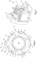
Figure 1 shows a top perspective view of some components of a cooling system according to a first embodiment of the present invention; -
figure 2 shows a top view of the cooling system offigure 1 ; -
figure 3 shows a top perspective view of some components of a cooling system according to a second embodiment of the present invention; -
figure 4 shows a top view of the cooling system offigure 2 ; -
figure 5 shows a top perspective view of some components of a cooling system according to a third embodiment of the present invention; -
figure 6 shows a top view of the cooling system offigure 5 ; -
figure 7 shows is a perspective view of a cooling circuit associated to the systems offigure 1 ,3 or5 ;figure 8 shows a bottom perspective view of the cooling system offigure 3 ; -
figure 9 is a perspective view of the central body of the cooling system offigure 2 ; -
figure 10 is a perspective view of a Peltier cell of the cooling system offigure 2 . - With reference to the attached figures, a cooling system, overall indicated by 10', 10", 10 III, is shown, particularly for use in a machine (not shown in the attached figures) for processing, thus cooling, a mixture, such as for example a food mixture for the production of ice cream.
- According to the present invention, as illustrated in
figures 1-6 thecooling system 10', 10", 10 III comprises acentral body 1', 1", 1 III which in turn comprises a workingcavity 100 suitable for housing the mixture and/or the products to be cooled, directly or through a further container. - The working
cavity 100 defines an axis AXC which is the rotation axis around which a possible rotor - for example one or more blades or scrapers of a creaming machine - arranged in thecavity 100 rotates, and/or is the symmetrical axis of thecavity 100 if it has a substantially cylindrical or prismatic shape and/or the axis of the cone, truncated cone, pyramid, or truncated pyramid possibly formed by the working cavity 100 (figure 1 ). - The
central body 1', 1", 1 III preferably forms external flanks extending substantially parallel or longitudinal to the axis AXC of theworking cavity 100. - The
central body 1', 1", 1 III is preferably made of a material having a high thermal conductivity such as for example aluminium, copper, steel, or other metallic material. - As for example in
figures 1 ,2 , , the system 10' can comprise three or morePeltier cells 2 arranged laterally to thecentral body 1', 1", 1 III and directly contacting thecentral body 1', 1", 1 III itself. - Preferably, each Peltier
cell 2 has an overall flat shape so as to form two greater faces each of which facing a direction of the space substantially opposite to that the other plate faces. - For this purpose, each Peltier
cell 2 can have a substantially plate shape, preferably flat (figures 1- 6) . - Preferably, the
Peltier cells 2 are arranged so as to have one of the greater faces contacting thecentral body 1', 1", 1 III, so as to promote the heat transmission to and from the body 1'. - For this purpose, the
central body 1', 1", 1 III preferably forms one or more coupling faces 11 configured for coupling with a respective greater face of aPeltier cell 2, particularly with the cold face of such cell; for this purpose, eachcoupling face 11 can have a substantially flat shape, or otherwise substantially complementary to - or having the cast of - the greater face of thePeltier cell 2. - The one or
more coupling faces 11 is preferably formed on the external flanks of thecentral body 1', 1", 1 III (figure 9 ) . - The cooling system 10' preferably comprises one or
more heat sinks 3 for example in a number corresponding to the number of Peltiercells 2 and suitable for keeping the temperature of the same under control during the steps of cooling the food mixture. - The cooling system 10' can comprise a variable number of
Peltier cells 2 depending on the requirements, therefore on the required cooling power, which can be arranged both laterally to and below thecentral body 1', 1", 1 III. - According to an aspect of the present invention, the cooling system 10' comprises at least three
Peltier cells 2 and accordingly a corresponding number ofheat sinks 3 associated to each Peltier cell (figures 1 ,2 ). - The cooling system 10' can possibly comprise even at least four Peltier cells 2 (
figures 3 ,4 ), at least five Peltier cells 2 (figures 5 ,6 ), at least sixPeltier cells 2, at least seven Peltiercells 2, at least eightPeltier cells 2, and for example three, four, five, six, seven, eight, nine, ten, or morePeltier cells 2 each of which arranged for example on the external flanks of thecentral body 1', 1", 1 III. - The cooling system 10' further comprises an assembling system 5' which keeps the
central body 1', 1", 1 III, the three or morePeltier cells 2 and the corresponding three ormore cooling subunits 3 assembled. - According to an aspect of the invention the assembling system 5' in turn comprises a
belt element 51 and atensioner 55. - The
belt element 51 extends around the at least threePeltier cells 2 and therelative heat sinks 3. - The
tensioner 55 is configured for tensioning thebelt element 51 by reducing or tending to reduce the perimeter of the portion of thebelt element 51 extending around the at least threePeltier cells 2 and the one or morepossible heat sinks 3 so as to tighten the at least threePeltier cells 2 against the external flanks of thecentral body 1', 1", 1III and fix the at least three Peltiercells 2 to said external flanks. - For this purpose, the
tensioner 55 is configured for tensioning thebelt element 51 so as to approach or tend to approach each other at least twoproximity sections single proximity sections 510, 512 - adjacent to the tensioner 55 - for example the closest to the tensioner 55 - so as to tighten the at least three Peltiercells 2 against the external flanks of thecentral body 1', 1", 1 III and fix the at least three Peltiercells 2 to said external flanks. - The
belt element 51 can comprise for example a wire (figures 1-6 ), a band or strip, a chain, a membrane, a coil spring; preferably, such elements can be made for example of steel or other metallic material but can be also made of a synthetic resin or other non-metallic materials. - Making the
belt element 51 of metallic material, especially if in the form of a metallic wire, facilitates its sliding on themechanical adapters 57 while theelement 51 is tightened around them, or otherwise tensioned. - The
belt element 51 is preferably coated by a layer of anti-corrosion material. - The
tensioner 55 can comprise for example a screw drive configured for approaching each other the twoproximity sections belt element 51, for example by pulling or pushing the twoproximity sections sections belt element 51. - For this purpose, the
tensioner 55 can comprise for example ascrew 514 configured for screwing and unscrewing in a nut screw by rotating around an axis substantially parallel or longitudinal to the twoproximity sections 510, 512 (figures 1 ,3, 5 ). - Alternatively, the
tensioner 55 can comprise for example a cam, lever, or inclined plane system and be driven thereby. - Possibly, the
screw 514 or other screw or a screw, cam, lever, or inclined plane drive of thetensioner 55 can be configured for tensioning thebelt element 51 by reducing or tending to reduce the perimeter of the portion of thebelt element 51 extending around the at least threePeltier cells 2 and the one or morepossible heat sinks 3 so as to tighten the at least threePeltier cells 2 against the external flanks of thecentral body 1', 1", 1III and fix the at least threePeltier cells 2 to said external flanks. - Possibly, a
single screw 514 or another single screw, a single screw drive, a single cam, a single lever, or a single inclined plane can be configured for tensioning thebelt element 51 by reducing or tending to reduce the perimeter of the portion of thebelt element 51 extending around the at least threePeltier cells 2 and the one or morepossible heat sinks 3 so as to tighten the at least threePeltier cells 2 against the external flanks of thecentral body 1', 1", 1III and fix the at least threePeltier cells 2 to said external flanks. - Preferably, the assembling system 5' comprises a
single belt element 51 and/or asingle tensioner 55. - Preferably, each
tensioner 55 is configured for tensioning asingle belt element 51 so as to reduce or tend to reduce the perimeter of the portion of thebelt element 51 extending around all the three of the at least threePeltier cells 2 and the one or morepossible heat sinks 3, by tightening the at least threePeltier cells 2 against the external flanks of thecentral body 1', 1", 1III and fixing the at least threePeltier cells 2 to said external flanks. - Advantageously, the assembling system 5' further comprises one or more
mechanical adapters 57 each of which is interposed between thebelt element 51 and one ormore heat sinks 3 or otherwise one ormore Peltier cells 2 so as to transmit tosuch cells 2 and possibly to thesinks 3 the thrust applied by thebelt element 51 towards the workingcavity 100 and/or towards the centre of thecentral body 1', 1", 1 III. - Each
mechanical adapter 57 can be made for example like a bearing or pad preferably made of a relatively rigid and slick material such as for example polyoxymethylene (POM or acetal resin), polyamide (PA), or polytetrafluoroethylene (Teflon (R)) so as to reduce the friction with thebelt element 51. - A reduced friction between the
mechanical adapters 57 and thebelt element 51 makes the tangential forces applied by the latter to theadapters 57 when it is tightened - o otherwise tensioned - and accordingly applied by theadapters 57 to thePeltier cells 2 negligible, improving the adherence and the contact of the adapters against thecells 2 and therefore the performance of the latter. - Still in order to reduce the friction between the
belt element 51 and themechanical adapters 57, each of them preferably forms one or more ribs, corrugations, studs orother protrusions 570 on its face - or other surface - which rests against thebelt element 51 or in any case faces it so as to reduce the surface contacting the belt element 51 (figures 1 ,3, 5 ). - Indeed, the pressure between the
Peltier cells 2 and thecentral body 1', 1", 1 III is very important in order to keep the efficiency of thecooling system 10', 10", 10 III high, while the pressure between thePeltier cells 2 and theheat sinks 3 is very important for the good operation of thePeltier cells 2 themselves, preventing them from overheating. - Preferably, the
cooling system 10', 10", 10 III further comprises a base element 4 made of a thermal insulating material suitable for acting as a base and meanwhile as a mounting mask for thecooling system 10 itself on the machine in which it is used. - Particularly, the
heat sinks 3 can be of the liquid type and be fluidically or otherwise functionally connected to acooling circuit 30, illustrated infigure 7 , comprising at least aradiator 31, atank 32, and to apump 33 for recirculating the cooling liquid and comprise at least an inlet piping and an outlet piping of the cooling liquid preferably made of copper. - As visible in
figures 1-6 , it consists of heat exchangers having the external shape for example of a block and in which the cooling liquid circulates due to the thrust of thepump 33. - In each
heat sink 3 the heat carrier liquid goes in and out through a respective inlet and outlet piping. - Advantageously, the cooling liquid can be water or any other type of cooling liquid.
-
Figure 7 illustrates a possible embodiment of thecooling circuit 30 inside a machine. - Furthermore, the
Peltier cells 2 can be powered for example at 15 V by an electrical energy source arranged for example in the machine. - Each
Peltier cell 2, as illustrated infigure 10 , preferably comprises a shell of two ceramic plates which sandwich semiconductors which, passed through by direct current, cool one of the two plates and heat the other. - In such case, the ceramic plate facing the
central body 1', 1", 1 III will be cooled, thus cooling the content of thecentral body 1', 1", 1 III itself, while the ceramic plate facing the opposite side will be heated in a controlled manner due to theheat sinks 3 associated to eachPeltier cell 2. - Possibly, by inverting the polarity of the electrical power of the
Peltier cells 2, these can be used to heat the ceramic plate facing thecentral body 1', 1", 1III, thus heating the content of thecentral body 1', 1", 1 III itself, and instead cooling the ceramic plate facing the opposite side; in such case theheat sinks 3 are preferably deactivated, if they are active and not only passive components. - Still preferably, the
base element 2 is made of synthetic resin. - The operation of the cooling system is as follows.
- The mixture of ingredients to be cooled is inserted into the working
cavity 100 and the machine, particularly itscooling system 10', 10", 10III, are activated. - Therefore, the semiconductors present in the
Peltier cells 2 are passed through by a direct current, provided by the power supply present in the machine, which causes a side of them to be cooled, particularly that contacting thecentral body 1', 1", 1 III, and the opposite side to be heated. - Meanwhile, the
heat sinks 3 are activated, which due to thecooling circuit 30 are passed through by a cooling liquid suitable for keeping the temperature of the side of thePeltier cells 2 facing them under control. - Such system allows to obtain the freezing of the mixture inside the central body in about 180 seconds.
- The features and advantages of the system being the object of the present invention are apparent from the preceding description; particularly, it is apparent that the same the
belt element 51, thesame tensioner 55 and the samemechanical adapters 57 can be mounted without needing any modification in coolingsystems 10', 10", 10 III provided with a different number ofPeltier cells 2; this allows to remarkably standardize the required components to produce a wide range of cooling systems, to reduce the number of such components and their production costs due to the greater scale economies. - Reducing the production costs is also facilitated by the attitude of the
belt element 51 and thetensioner 55 to be made with extremely simple shapes and mechanisms. - It is clear, finally, that the system thus conceived is susceptible of a number of modifications and variations without departing from the scope of the present invention; for example, each wire, band, strip, chain, or membrane pertaining to the
belt element 51 and for example forming it can be wound around the at least threePeltier cells 2, so as to tighten them, forming one or more turns. - Furthermore, all the details are replaceable by technically equivalent elements.
- In practice, the used materials, as well as the size, can be any depending on the technical requirements.
Claims (13)
- Cooling system (10', 10", 10 III) for a machine for processing a mixture comprising:- a central body (1', 1", 1 III) suitable for housing the mixture and/or products to be cooled and which forms external flanks;- at least three Peltier cells (2) each of which resting on said external flanks of the central body- one or more heat sinks (3) configured for regulating the temperature of the at least three Peltier cells (2) for example by cooling them;wherein said cooling system (10) further comprises an assembling system (5') in turn comprising a belt element (51) and a tensioner (55) and in which:- the belt element (51) extends around the at least three Peltier cells (2) and the one or more possible heat sinks (3);- the tensioner (55) is configured for tensioning the belt element (51) by reducing or tending to reduce the perimeter of the portion of the belt element (51) extending around the at least three Peltier cells (2) and the one or more possible heat sinks (3) so as to tighten the at least three Peltier cells (2) against the external flanks of the central body (1', 1", 1 III) and fix the at least three Peltier cells (2) to said external flanks.
- Cooling system according to claim 1, in which the tensioner (55) is configured for tensioning the belt element (51) so as to approach or tend to approach each other at least two proximity sections (510, 512) of the belt element (51) adjacent to the tensioner, so as to tighten the at least three Peltier cells (2) against the external flanks of the central body (1) and fix the at least three Peltier cells (2) to said external flanks.
- Cooling system (10) according to claim 1 or 2, in which the tensioner (55) is configured for approaching or tending to approach each other at least two proximity sections (510, 512) of the belt element (51) adjacent to the tensioner (55), respectively by sliding, or tending to slide, the two proximity sections (510, 512) in directions substantially parallel or longitudinal to the sections (510, 512) themselves.
- Cooling system (10) according to one or more preceding claims, in which the belt element (51) comprises one or more of the following elements: a wire (51), a band or strip, a chain, a membrane, wherein such elements are for example made of steel or other metallic material.
- Cooling system (10) according to claim 4, in which the belt element (51) comprises a single specimen of one or more elements selected from the following group:
a wire (51), a band or strip, a chain, a membrane, wherein:- such elements are for example made of steel or other metallic material; and- each of such elements is configured for being tensioned by the tensioner (55) so as to tighten the at least three Peltier cells (2) against the external flanks of the central body (1', 1", 1 III) and fix the at least three Peltier cells (2) to said external flanks. - Cooling system (10) according to claim 5, in which the belt element (51) comprises a single specimen of only one of the following elements: a wire (51), a band or strip, a chain, a membrane, wherein:- such elements are for example made of steel or other metallic material; and- each of such elements is configured for being tensioned by the tensioner (55) so as to tighten the at least three Peltier cells (2) against the external flanks of the central body (1', 1", 1IIII ) and fix the at least three Peltier cells (2) to said external flanks.
- Cooling system (10) according to one or more preceding claims, comprising at least four Peltier cells (2), or at least five Peltier cells (2), at least six Peltier cells (2), at least seven Peltier cells (2), at least eight Peltier cells (2).
- Cooling system (10) according to one or more preceding claims, comprising one or more mechanical adapters (57) each of which is interposed between the belt element (51) and one or more Peltier cells (2) so as to transmit to these cells (2) the thrust applied by the belt element (51) towards the working cavity (100) and/or towards the centre of the central body (1', 1", 1III ).
- Cooling system (10) according to claim 8, in which one or more of the mechanical adapters (57) are overall softer or more compliant than the Peltier cell portion (2), of the belt element (51) closest thereto so as to make the pressure applied by the belt element (51) more uniform in space and more constant over time on the Peltier cells (2) and on the one or more possible heat sinks (3) by fixing more firmly and stably the at least three Peltier cells (2) and the one or more possible heat sinks (3) to the flanks of the central body (1', 1", 1III ).
- Cooling system (10) according to claim 8 or 9, in which one or more of the mechanical adapters (57) forms one or more ribs, ridges, corrugations, studs or other protrusions on its face - or other surface - which rests against the belt element (51) or in any case faces the belt element (51) to promote sliding between the belt element (51) and the relative mechanical adapter (57).
- Cooling system (10) according to one or more preceding claims, in which the tensioner (55) comprises a screw, cam, inclined plane, and/or lever drive configured for approaching or tending to approach each other the two proximity sections (510, 512) of the belt element (51), for example by pulling or pushing the two proximity sections (510, 512).
- Cooling system (10) according to one or more claims 8 to 10, in which one or more of the mechanical adapters (57) are made of or otherwise contain synthetic resin.
- Machine for the production of ice creams comprising a cooling system (10', 10", 10III ) having the features according to one or more preceding claims.
Applications Claiming Priority (1)
| Application Number | Priority Date | Filing Date | Title |
|---|---|---|---|
| IT102023000008244A IT202300008244A1 (en) | 2023-04-27 | 2023-04-27 | COOLING SYSTEM AND ICE CREAM MAKING MACHINE INCLUDING SUCH SYSTEM. |
Publications (1)
| Publication Number | Publication Date |
|---|---|
| EP4454476A1 true EP4454476A1 (en) | 2024-10-30 |
Family
ID=87419122
Family Applications (1)
| Application Number | Title | Priority Date | Filing Date |
|---|---|---|---|
| EP24171706.5A Pending EP4454476A1 (en) | 2023-04-27 | 2024-04-22 | Cooling system and machine for the production of ice creams comprising such system |
Country Status (5)
| Country | Link |
|---|---|
| US (1) | US20240361048A1 (en) |
| EP (1) | EP4454476A1 (en) |
| KR (1) | KR20240158800A (en) |
| CN (1) | CN118856642A (en) |
| IT (1) | IT202300008244A1 (en) |
Citations (5)
| Publication number | Priority date | Publication date | Assignee | Title |
|---|---|---|---|---|
| EP2266418A1 (en) * | 2009-06-26 | 2010-12-29 | Nestec S.A. | Container having ingredients for preparing a frozen confection, container holder and device for preparing a frozen confection |
| CN104171249A (en) * | 2014-09-02 | 2014-12-03 | 广东富信科技股份有限公司 | Ice cream machine |
| CN214546990U (en) * | 2021-02-25 | 2021-11-02 | 广东富信科技股份有限公司 | An ice cream machine with micro-flow cooling channel |
| CN214710116U (en) * | 2021-05-04 | 2021-11-16 | 河南鸿昌电子有限公司 | Asymmetric ice-cream machine of many refrigeration pieces |
| WO2022084882A1 (en) * | 2020-10-21 | 2022-04-28 | Tooa S.P.A. | Cooling system |
Family Cites Families (1)
| Publication number | Priority date | Publication date | Assignee | Title |
|---|---|---|---|---|
| KR20220095794A (en) * | 2020-12-30 | 2022-07-07 | 코웨이 주식회사 | Apparatus for making cold water and water purifier including the same |
-
2023
- 2023-04-27 IT IT102023000008244A patent/IT202300008244A1/en unknown
-
2024
- 2024-04-22 EP EP24171706.5A patent/EP4454476A1/en active Pending
- 2024-04-22 US US18/641,759 patent/US20240361048A1/en active Pending
- 2024-04-22 CN CN202410483280.XA patent/CN118856642A/en active Pending
- 2024-04-22 KR KR1020240053373A patent/KR20240158800A/en active Pending
Patent Citations (5)
| Publication number | Priority date | Publication date | Assignee | Title |
|---|---|---|---|---|
| EP2266418A1 (en) * | 2009-06-26 | 2010-12-29 | Nestec S.A. | Container having ingredients for preparing a frozen confection, container holder and device for preparing a frozen confection |
| CN104171249A (en) * | 2014-09-02 | 2014-12-03 | 广东富信科技股份有限公司 | Ice cream machine |
| WO2022084882A1 (en) * | 2020-10-21 | 2022-04-28 | Tooa S.P.A. | Cooling system |
| CN214546990U (en) * | 2021-02-25 | 2021-11-02 | 广东富信科技股份有限公司 | An ice cream machine with micro-flow cooling channel |
| CN214710116U (en) * | 2021-05-04 | 2021-11-16 | 河南鸿昌电子有限公司 | Asymmetric ice-cream machine of many refrigeration pieces |
Also Published As
| Publication number | Publication date |
|---|---|
| IT202300008244A1 (en) | 2024-10-27 |
| US20240361048A1 (en) | 2024-10-31 |
| CN118856642A (en) | 2024-10-29 |
| KR20240158800A (en) | 2024-11-05 |
Similar Documents
| Publication | Publication Date | Title |
|---|---|---|
| EP0605664B1 (en) | Thermoelectric refrigeration system with flexible heat-conducting element | |
| US20230249957A1 (en) | Refrigeration systems for rapidly cooling food and drinks | |
| AU2017278943B2 (en) | Cylindrical heat exchanger | |
| EP3679803B1 (en) | Stirring device of a machine for making liquid or semiliquid food products | |
| US4540288A (en) | Apparatus for producing ice cream utilizing the Peltier effect | |
| US6664627B2 (en) | Water cooling type cooling block for semiconductor chip | |
| CA1229364A (en) | Rotating rectifier assembly | |
| US4143711A (en) | Portable refrigerator unit | |
| US5456081A (en) | Thermoelectric cooling assembly with optimized fin structure for improved thermal performance and manufacturability | |
| EP3836795A1 (en) | Providing single servings of cooled foods and drinks | |
| CN1711449A (en) | Integrated thermoelectric module | |
| US4576016A (en) | Ice making apparatus | |
| US20090052274A1 (en) | Apparatus for Heat Exchange with Radial Mixing | |
| EP0894230A1 (en) | Ice-making machine and heat exchanger therefor | |
| US20240361048A1 (en) | Cooling system and machine for the production of ice creams comprising such system | |
| WO1995000223A1 (en) | Heat transfer apparatus with positive drive orbital whip rod | |
| US20220021049A1 (en) | Cooling structure for hybrid-electric vehicle battery cell assemblies | |
| KR19980054659A (en) | Chiller of ice cream maker | |
| US20040163406A1 (en) | Auger type ice-making machine | |
| KR102062630B1 (en) | Thermoelectric Generation Module Adaptive to Temperature Condition | |
| WO2016207153A1 (en) | Temperature-control unit for a gaseous or liquid medium | |
| US20050204749A1 (en) | Scraped surface heat exchanger for continuous heating or cooling of viscous masses | |
| US3360942A (en) | Thermoelectric heat pump assembly | |
| EP3108748B1 (en) | Aquarium thermostat using plurality of peltier elements and method for adjusting breeding water temperature | |
| WO2022084882A1 (en) | Cooling system |
Legal Events
| Date | Code | Title | Description |
|---|---|---|---|
| PUAI | Public reference made under article 153(3) epc to a published international application that has entered the european phase |
Free format text: ORIGINAL CODE: 0009012 |
|
| STAA | Information on the status of an ep patent application or granted ep patent |
Free format text: STATUS: THE APPLICATION HAS BEEN PUBLISHED |
|
| AK | Designated contracting states |
Kind code of ref document: A1 Designated state(s): AL AT BE BG CH CY CZ DE DK EE ES FI FR GB GR HR HU IE IS IT LI LT LU LV MC ME MK MT NL NO PL PT RO RS SE SI SK SM TR |
|
| STAA | Information on the status of an ep patent application or granted ep patent |
Free format text: STATUS: REQUEST FOR EXAMINATION WAS MADE |
|
| 17P | Request for examination filed |
Effective date: 20250429 |
|
| STAA | Information on the status of an ep patent application or granted ep patent |
Free format text: STATUS: EXAMINATION IS IN PROGRESS |
|
| 17Q | First examination report despatched |
Effective date: 20250828 |
|
| GRAP | Despatch of communication of intention to grant a patent |
Free format text: ORIGINAL CODE: EPIDOSNIGR1 |
|
| STAA | Information on the status of an ep patent application or granted ep patent |
Free format text: STATUS: GRANT OF PATENT IS INTENDED |
|
| INTG | Intention to grant announced |
Effective date: 20260220 |