EP4451785A1 - Prach-übertragungsverfahren und -vorrichtung sowie endgerät - Google Patents
Prach-übertragungsverfahren und -vorrichtung sowie endgerät Download PDFInfo
- Publication number
- EP4451785A1 EP4451785A1 EP22906504.0A EP22906504A EP4451785A1 EP 4451785 A1 EP4451785 A1 EP 4451785A1 EP 22906504 A EP22906504 A EP 22906504A EP 4451785 A1 EP4451785 A1 EP 4451785A1
- Authority
- EP
- European Patent Office
- Prior art keywords
- prach
- transmission
- repeated transmission
- power
- sending
- Prior art date
- Legal status (The legal status is an assumption and is not a legal conclusion. Google has not performed a legal analysis and makes no representation as to the accuracy of the status listed.)
- Pending
Links
Images

Classifications
-
- H—ELECTRICITY
- H04—ELECTRIC COMMUNICATION TECHNIQUE
- H04W—WIRELESS COMMUNICATION NETWORKS
- H04W52/00—Power management, e.g. Transmission Power Control [TPC] or power classes
- H04W52/04—Transmission power control [TPC]
- H04W52/18—TPC being performed according to specific parameters
- H04W52/24—TPC being performed according to specific parameters using SIR [Signal to Interference Ratio] or other wireless path parameters
-
- H—ELECTRICITY
- H04—ELECTRIC COMMUNICATION TECHNIQUE
- H04W—WIRELESS COMMUNICATION NETWORKS
- H04W52/00—Power management, e.g. Transmission Power Control [TPC] or power classes
- H04W52/04—Transmission power control [TPC]
- H04W52/06—TPC algorithms
- H04W52/14—Separate analysis of uplink or downlink
-
- H—ELECTRICITY
- H04—ELECTRIC COMMUNICATION TECHNIQUE
- H04W—WIRELESS COMMUNICATION NETWORKS
- H04W52/00—Power management, e.g. Transmission Power Control [TPC] or power classes
- H04W52/04—Transmission power control [TPC]
- H04W52/06—TPC algorithms
- H04W52/14—Separate analysis of uplink or downlink
- H04W52/146—Uplink power control
-
- H—ELECTRICITY
- H04—ELECTRIC COMMUNICATION TECHNIQUE
- H04W—WIRELESS COMMUNICATION NETWORKS
- H04W52/00—Power management, e.g. Transmission Power Control [TPC] or power classes
- H04W52/04—Transmission power control [TPC]
- H04W52/18—TPC being performed according to specific parameters
- H04W52/24—TPC being performed according to specific parameters using SIR [Signal to Interference Ratio] or other wireless path parameters
- H04W52/242—TPC being performed according to specific parameters using SIR [Signal to Interference Ratio] or other wireless path parameters taking into account path loss
-
- H—ELECTRICITY
- H04—ELECTRIC COMMUNICATION TECHNIQUE
- H04W—WIRELESS COMMUNICATION NETWORKS
- H04W52/00—Power management, e.g. Transmission Power Control [TPC] or power classes
- H04W52/04—Transmission power control [TPC]
- H04W52/30—Transmission power control [TPC] using constraints in the total amount of available transmission power
- H04W52/32—TPC of broadcast or control channels
- H04W52/325—Power control of control or pilot channels
-
- H—ELECTRICITY
- H04—ELECTRIC COMMUNICATION TECHNIQUE
- H04W—WIRELESS COMMUNICATION NETWORKS
- H04W52/00—Power management, e.g. Transmission Power Control [TPC] or power classes
- H04W52/04—Transmission power control [TPC]
- H04W52/30—Transmission power control [TPC] using constraints in the total amount of available transmission power
- H04W52/36—Transmission power control [TPC] using constraints in the total amount of available transmission power with a discrete range or set of values, e.g. step size, ramping or offsets
-
- H—ELECTRICITY
- H04—ELECTRIC COMMUNICATION TECHNIQUE
- H04W—WIRELESS COMMUNICATION NETWORKS
- H04W52/00—Power management, e.g. Transmission Power Control [TPC] or power classes
- H04W52/04—Transmission power control [TPC]
- H04W52/30—Transmission power control [TPC] using constraints in the total amount of available transmission power
- H04W52/36—Transmission power control [TPC] using constraints in the total amount of available transmission power with a discrete range or set of values, e.g. step size, ramping or offsets
- H04W52/362—Aspects of the step size
-
- H—ELECTRICITY
- H04—ELECTRIC COMMUNICATION TECHNIQUE
- H04W—WIRELESS COMMUNICATION NETWORKS
- H04W52/00—Power management, e.g. Transmission Power Control [TPC] or power classes
- H04W52/04—Transmission power control [TPC]
- H04W52/38—TPC being performed in particular situations
- H04W52/48—TPC being performed in particular situations during retransmission after error or non-acknowledgment
-
- H—ELECTRICITY
- H04—ELECTRIC COMMUNICATION TECHNIQUE
- H04W—WIRELESS COMMUNICATION NETWORKS
- H04W52/00—Power management, e.g. Transmission Power Control [TPC] or power classes
- H04W52/04—Transmission power control [TPC]
- H04W52/38—TPC being performed in particular situations
- H04W52/50—TPC being performed in particular situations at the moment of starting communication in a multiple access environment
-
- H—ELECTRICITY
- H04—ELECTRIC COMMUNICATION TECHNIQUE
- H04W—WIRELESS COMMUNICATION NETWORKS
- H04W72/00—Local resource management
- H04W72/04—Wireless resource allocation
- H04W72/044—Wireless resource allocation based on the type of the allocated resource
- H04W72/0473—Wireless resource allocation based on the type of the allocated resource the resource being transmission power
-
- H—ELECTRICITY
- H04—ELECTRIC COMMUNICATION TECHNIQUE
- H04W—WIRELESS COMMUNICATION NETWORKS
- H04W74/00—Wireless channel access
- H04W74/08—Non-scheduled access, e.g. ALOHA
- H04W74/0833—Random access procedures, e.g. with 4-step access
Definitions
- This application relates to the field of communication technologies, and specifically, to a PRACH transmission method and apparatus, and a terminal.
- Physical Random access channel (Physical Random Access Channel, PRACH) repeated transmission is a method for enhancing PRACH coverage.
- a user equipment User Equipment, UE selects the PRACH repeated transmission usually in a case of poor coverage.
- An initial power of the PRACH transmission in the related art comprehensively takes into account all terminals in a cell, including terminals with limited coverage and unlimited coverage, and usually does not reach a maximum power. A maximum value is only reached after a plurality of times of retransmission and power ramping.
- Embodiments of this application provide a PRACH transmission method and apparatus, and a terminal, which can resolve a problem of how to determine a sending power of each PRACH transmission in PRACH repeated transmission in the related art.
- a PRACH transmission method including:
- a PRACH transmission apparatus including:
- a terminal includes a processor and a memory.
- the memory stores a program or instructions executable on the processor.
- the program or the instructions when executed by the processor, implement steps of the method according to the first aspect.
- a terminal including a processor and a communication interface.
- the processor is configured to determine a sending power of a physical random access channel PRACH repeated transmission according to a target indication.
- the target indication is used for indicating whether sending powers of PRACH transmissions in the PRACH repeated transmission are the same.
- the communication interface is configured to perform PRACH repeated transmission according to the sending power of the PRACH repeated transmission.
- a communication system including: a terminal and a network side device.
- the terminal may be configured to perform steps of the PRACH transmission method according to the first aspect.
- a readable storage medium having a program or instructions stored therein.
- the program or the instructions when executed by a processor, implement steps of the method according to the first aspect.
- a chip including a processor and a communication interface.
- the communication interface is coupled to the processor.
- the processor is configured to execute a program or instructions, to implement steps of the method according to the first aspect.
- a computer program/program product is provided.
- the computer program/program product is stored in a storage medium.
- the computer program/program product is executed by at least one processor to implement steps of the method according to the first aspect.
- the terminal determines the sending power of the PRACH repeated transmission according to the target indication.
- the target indication is used for indicating whether the sending powers of the PRACH transmissions in the PRACH repeated transmission are the same.
- the terminal performs PRACH repeated transmission according to the sending power of the PRACH repeated transmission.
- the terminal may determine whether the sending powers of the PRACH transmissions in the PRACH repeated transmission are the same according to the target indication, to flexibly determine the sending power of the PRACH transmission in the PRACH repeated transmission, thereby improving transmission performance.
- first, second, and the like are used to distinguish similar objects, but are unnecessarily used to describe a specific sequence or order. It may be understood that the terms used in such a way is interchangeable in proper circumstances, so that the embodiments of this application described herein can be implemented in other sequences than the sequence illustrated or described herein.
- the objects distinguished by “first” and “second” are usually of one type, and a number of objects is not limited, for example, a first object may be one or more first objects.
- “and/or” in the specification and claims indicates at least one of connected objects, and a character “/" generally indicates that connected objects are in an "or” relationship.
- LTE Long Term Evolution
- LTE-A Long Term Evolution-Advanced
- CDMA code division multiple access
- Time Division Multiple Access Time Division Multiple Access
- FDMA frequency division multiple access
- OFDMA Orthogonal Frequency Division Multiple Access
- SC-FDMA single carrier frequency division multiple access
- system and “network” in the embodiments of this application may usually be used interchangeably, and the technology described can be applied to the systems and radio technologies mentioned above, and can also be applied to other systems and radio technologies.
- the following description describes a new radio (New Radio, NR) system for example purposes, and NR terminology is used in most of the following description, but these techniques can also be applied to applications other than NR system applications, such as a 6th generation (6th Generation, 6G) communication system.
- NR New Radio
- 6G 6th Generation
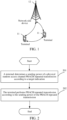
- FIG. 1 is a block diagram of a wireless communication system to which an embodiment of this application may be applied.
- the wireless communication system includes a terminal 11 and a network side device 12.
- the terminal 11 may be terminal side devices such as a mobile phone, a tablet personal computer (Tablet Personal Computer), a laptop computer (Laptop Computer) or a notebook computer, a personal digital assistant (Personal Digital Assistant, PDA), a palmtop computer, a netbook, an ultra-mobile personal computer (ultra-mobile personal computer, UMPC), a mobile Internet device (Mobile Internet Device, MID), an augmented reality (Augmented Reality, AR) or a virtual reality (Virtual Reality, VR) device, a robot, a wearable device (Wearable Device), a vehicle user equipment (Vehicle User Equipment, VUE), a pedestrian user equipment (Pedestrian User Equipment, PUE), a smart household (a household device with a wireless communication function, such as a refrigerator, a television, a washing machine, or furniture), a
- the wearable device includes: a smart watch, a smart bracelet, a smart earphone, smart glasses, smart jewelry (a smart bangle, a smart wrist chain, a smart ring, a smart necklace, a smart anklet, a smart ankle chain, and the like), a smart wristband, smart clothes, and the like.
- the network side device 12 may include an access network device or a core network device.
- the access network device 12 may also be referred to as an access network device, a radio access network (Radio Access Network, RAN), a radio access network function, or a radio access network unit.
- RAN Radio Access Network
- the access network device 12 may include a base station, a wireless local area network (Wireless Local Area Network, WLAN) access point, a wireless fidelity (Wireless Fidelity, Wi-Fi) node, or the like.
- the base station may be referred to as a NodeB, an evolved NodeB (eNB), an access point, a base transceiver station (Base Transceiver Station, BTS), a radio base station, a radio transceiver, a basic service set (Basic Service Set, BSS), an extended service set (Extended Service Set, ESS), a home NodeB, a home evolved NodeB, a transmitting receiving point (Transmitting Receiving Point, TRP), or another proper term in the field.
- the base station is not limited to a specific technical term. It should be noted that in the embodiments of this application, the base station in the NR system is only used as an example for description, and a specific type of the base station is not limited.
- FIG. 2 is a flowchart of a PRACH transmission method according to an embodiment of this application.
- the PRACH transmission method includes the following steps.
- Step 201 A terminal determines a sending power of a PRACH repeated transmission according to a target indication, where the target indication is used for indicating whether sending powers of PRACH transmissions in the PRACH repeated transmission are the same.
- the target indication includes at least one of a protocol specified indication, a network side device indication, and a downlink control information (Downlink Control Information, DCI) indication of a physical downlink control channel (Physical Downlink Control Channel, PDCCH).
- a protocol specifies that each time of (or each) PRACH transmission in the PRACH repeated transmission has a same sending power or different sending powers; or a network side device indicates that each PRACH transmission in the PRACH repeated transmission has a same sending power or different sending powers; or the DCI of the PDCCH indicates that each PRACH transmission in the PRACH repeated transmission has a same sending power or different sending powers.
- Step 202 The terminal performs PRACH repeated transmission according to the sending power of the PRACH repeated transmission.
- the terminal determines the sending power of the PRACH repeated transmission according to the target indication.
- the target indication is used for indicating whether the sending powers of the PRACH transmissions in the PRACH repeated transmission are the same.
- the terminal performs PRACH repeated transmission according to the sending power of the PRACH repeated transmission.
- the terminal may determine whether the sending powers of the PRACH transmissions in the PRACH repeated transmission are the same according to the target indication, to flexibly determine the sending power of the PRACH transmission in the PRACH repeated transmission, thereby improving transmission performance.
- the sending power of the PRACH repeated transmission meets at least one of the following:
- the target indication may be used for indicating that each PRACH transmission in the PRACH repeated transmission has the same sending power.
- each PRACH transmission in the PRACH repeated transmissions is required to have the same sending power.
- the same sending power can be determined based on a path loss estimate obtained before the first PRACH transmission in the PRACH repeated transmission, that is, the sending power of each PRACH transmission is determined by using the path loss estimate.
- the network side device may determine, through an estimate receiving power transmitted by each PRACH transmission, which reference signal is the best reference signal in the reference signals associated with the PRACH transmission.
- the network side device indicates that each PRACH transmission in the PRACH repeated transmission has a same sending power or different sending powers, providing greater flexibility for the network side device. For example, when the network side device needs to determine which PRACH transmission received by the network side device has the best receiving power, the network side device may indicate to the terminal that each PRACH transmission uses a same path loss estimate. The same path loss estimate corresponds to the same sending power. In a case that the sending power of each PRACH transmission is the same, the network side device may determine which PRACH transmission has the best receiving power according to the receiving power.
- each PRACH transmission in the PRACH repeated transmission has a same sending power or different sending powers may alternatively be indicated by using DCI of a PDCCH; or in a case that each PRACH transmission in the PRACH repeated transmission has a same sending power, a reference signal used for estimating a path loss is indicated by using the DCI of the PDCCH.
- the sending power of the PRACH repeated transmission is determined by using power ramping, including one of the following:
- a power ramping counter configured for the PRACH repeated transmission suspends counting.
- the first preset condition includes at least one of the following:
- the another transmission in the above includes a physical uplink shared channel (Physical Uplink Shared Channel, PUSCH) transmission, a physical uplink control channel (Physical Uplink Control Channel, PUCCH), or a sounding reference signal (Sounding Reference Signal, SRS) transmission.
- PUSCH Physical Uplink Shared Channel
- PUCCH Physical Uplink Control Channel
- SRS Sounding Reference Signal
- the power ramping counter increases the count.
- the second preset condition includes: compared with the current PRACH transmission, a spatial domain transmission filter of the next PRACH transmission remains unchanged.
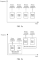
- the power ramping counter configured for the PRACH repeated transmission has a same count as a power ramping counter configured for PRACH retransmission. After each PRACH repeated transmission or each PRACH retransmission, the power continues to increase to an allowed maximum value.
- a PRACH initial transmission may include the PRACH repeated transmission
- the PRACH retransmission may also include the PRACH repeated transmission.
- the power ramping counter configured for the PRACH repeated transmission has the same count as the power ramping counter configured for the PRACH retransmission in FIG. 3b .
- Each PRACH includes the PRACH initial transmission and one PRACH retransmission.
- the PRACH initial transmission and the PRACH retransmission respectively has two repeated transmissions.
- reference signals associated with the two repeated transmissions are the same, and are both associated with SSB 1, and the power ramping counter increases the count from 1 to 2.
- Rep3 is associated with SSB2
- SSB2 is different from SSB1 with which the last PRACH transmission Rep2 in the PRACH initial transmission is associated
- the power ramping counter does not increase the count.
- the second PRACH transmission Rep4 in the PRACH retransmission is associated with the same reference signal as Rep3, because the reference signal associated with Rep4 is still SSB2.
- the power ramping counter further increases the count to 3.
- a maximum quantity of the PRACH transmission is: a sum of a maximum quantity of PRACH repeated transmissions included in PRACH initial transmission and a maximum quantity of PRACH repeated transmissions included in PRACH retransmission.
- a PRACH transmission count reaches a maximum value, a random access error is announced.
- a transmission quantity of random access of the terminal is the maximum quantity of the PRACH transmissions.
- the maximum quantity of the PRACH transmission is: a sum of a maximum quantity of PRACH repeated transmissions included in PRACH initial transmission and a maximum quantity of PRACH repeated transmissions included in PRACH retransmission.
- a maximum transmission count may alternatively be separately configured for the PRACH repeated transmission. If the PRACH repeated transmission supports the power ramping, because repetition has been performed on each transmission and retransmission, a relatively small maximum transmission count may be configured.
- each PRACH transmission in the PRACH repeated transmission may have a same sending power, or may have different sending powers.
- supporting the power ramping based on the PRACH repeated transmission is conducive to the PRACH transmission using a higher power, thereby further reducing a random access delay.
- the maximum quantity of the retransmission may be reduced compared with a case in which the PRACH repeated transmission is not performed, to determine to end a current random access process earlier.
- the PRACH transmission method provided in FIG. 2 of this application may be performed by a PRACH transmission apparatus 400.
- An apparatus for the PRACH transmission method provided in the embodiments of this application is described by using an example in which the PRACH transmission apparatus 400 performs the PRACH transmission method in this embodiment of this application.
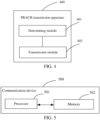
- an embodiment of this application provides a PRACH transmission apparatus 400, including:
- the sending power of the PRACH repeated transmission meets at least one of the following:
- a reference signal used for estimating a path loss is indicated by using downlink control information DCI of a PDCCH.
- the target indication includes at least one of the following information:
- the determining module 401 is further configured to determine the sending power of the PRACH repeated transmission through power ramping.
- the determining module 401 includes one of the following:
- the second determining sub-module is configured to perform power ramping on the PRACH repeated transmission in a case that the network side device configures a power ramping step.
- the third determining sub-module is configured to perform power ramping on the PRACH repeated transmission in a case that the expected transmission power of the network side device for each PRACH transmission in the PRACH repeated transmission is different.
- a power ramping counter configured for the PRACH repeated transmission suspends counting.
- the first preset condition includes at least one of the following:
- the another transmission includes a PUSCH transmission, a PUCCH transmission, or an SRS transmission.
- a power ramping counter increases a count.
- the second preset condition includes: compared with the current PRACH transmission, a spatial domain transmission filter of the next PRACH transmission remains unchanged.
- a power ramping counter configured for the PRACH repeated transmission has a same count as a power ramping counter configured for PRACH retransmission.
- a maximum quantity of the PRACH transmissions is: a sum of a maximum quantity of PRACH repeated transmissions included in PRACH initial transmission and a maximum quantity of PRACH repeated transmissions included in PRACH retransmission.
- a transmission quantity of random access of the terminal is the maximum quantity of the PRACH transmissions.
- the PRACH transmission apparatus 400 in this embodiment of this application may be an electronic device, for example, an electronic device with an operating system, or may be a component in the electronic device, for example, an integrated circuit or a chip.
- the electronic device may be a terminal, or may another device other than the terminal.
- the terminal may include, but is not limited to, a type of the terminal 11 listed above.
- the another device may be a server, network attached storage (Network Attached Storage, NAS), which is not specifically limited in this embodiment of this application.
- Network Attached Storage Network Attached Storage
- the PRACH transmission apparatus 400 provided in this embodiment of this application can implement processes implemented in the method embodiments of FIG. 2 , and the same technical effects can be achieved. To avoid repetition, details are not described herein again.
- an embodiment of this application further provides a communication device 500, including a processor 501 and a memory 502.
- the memory 502 stores a program or instructions executable on the processor 501.
- the program or the instructions when executed by the processor 501, implement processes of the PRACH transmission method embodiments shown in FIG. 2 , and can achieve a same technical effect, which is not repeated herein again.
- An embodiment of this application further provides a terminal, including a processor and a communication interface.
- the processor is configured to determine a sending power of a physical random access channel PRACH repeated transmission according to a target indication.
- the target indication is used for indicating whether sending powers of PRACH transmissions in the PRACH repeated transmission are the same.
- the communication interface is configured to perform PRACH repeated transmission according to the sending power of the PRACH repeated transmission.
- the terminal embodiment corresponds to the terminal side method embodiments, and all implementation processes and implementations of the method embodiments can be applied in the terminal embodiment, and can achieve a same technical effect.
- FIG. 6 is a schematic diagram of a hardware structure of a terminal implementing the embodiments of this application.
- the terminal 600 includes, but is not limited to: at least a part of components such as a radio frequency unit 601, a network module 602, an audio output unit 603, an input unit 604, a sensor 605, a display unit 606, a user input unit 607, an interface unit 608, a memory 609, and a processor 610.
- the terminal 600 may further include a power supply (such as a battery) for supplying power to the components.
- the power supply may be logically connected to the processor 610 by using a power management system, thereby implementing functions, such as charging, discharging, and power consumption management, by using the power management system.
- a terminal structure shown in FIG. 6 does not constitute a limitation to the terminal, and the terminal may include more or fewer components than those shown in the figure, or some components may be combined, or a different component deployment may be used. This is not described herein again.
- the input unit 604 may include a graphics processing unit (Graphics Processing Unit, GPU) 6041 and a microphone 6042.
- the graphics processing unit 6041 performs processing on image data of a static picture or a video that is obtained by an image acquisition device (for example, a camera) in a video acquisition mode or an image acquisition mode.
- the display unit 606 may include a display panel 6061, and the display panel 6061 may be configured by using a liquid crystal display, organic light-emitting diode, or the like.
- the user input unit 607 includes at least one of a touch panel 6071 and another input device 6072.
- the touch panel 6071 is also referred to as a touch screen.
- the touch panel 6071 may include two parts: a touch detection apparatus and a touch controller.
- the another input device 6072 may include, but is not limited to, a physical keyboard, a functional key (such as a volume control key or a switch key), a track ball, a mouse, and a joystick, which are not described herein again.
- the radio frequency unit 601 receives downlink data from a network side device, and then may transmit the downlink data to the processor 610 for processing. In addition, the radio frequency unit 601 may send uplink data to the network side device.
- the radio frequency unit 601 includes, but is not limited to, an antenna, an amplifier, a transceiver, a coupler, a low noise amplifier, a duplexer, and the like.
- the memory 609 may be configured to store a software program or instructions and various data.
- the memory 609 may mainly include a first storage area for storing a program or instructions and a second storage area for storing data.
- the first storage area may store an operating system, an application program or instructions required by at least one function (such as a sound playback function and an image display function), and the like.
- the memory 609 may include a volatile memory or a non-volatile memory, or the memory 609 may include both a volatile memory and a non-volatile memory.
- the non-volatile memory may be a read-only memory (Read-Only Memory, ROM), a programmable read-only memory (Programmable ROM, PROM), an erasable programmable read-only memory (Erasable PROM, EPROM), an electrically erasable programmable read-only memory (Electrically EPROM, EEPROM), or a flash memory.
- ROM Read-Only Memory
- PROM programmable read-only memory
- Erasable PROM Erasable PROM
- EPROM electrically erasable programmable read-only memory
- EEPROM electrically erasable programmable read-only memory
- the volatile memory may be a random access memory (Random Access Memory, RAM), a static random access memory (Static RAM, SRAM), a dynamic random access memory (Dynamic RAM, DRAM), a synchronous dynamic random access memory (Synchronous DRAM, SDRAM), a double data rate synchronous dynamic random access memory (Double Data Rate SDRAM, DDR SDRAM), an enhanced synchronous dynamic random access memory (Enhanced SDRAM, ESDRAM), a synch link dynamic random access memory (Synch link DRAM, SLDRAM), and a direct rambus random access memory (Direct Rambus RAM, DRRAM).
- RAM Random Access Memory
- SRAM static random access memory
- DRAM dynamic random access memory
- DRAM synchronous dynamic random access memory
- SDRAM double data rate synchronous dynamic random access memory
- Enhanced SDRAM, ESDRAM enhanced synchronous dynamic random access memory
- Synch link DRAM, SLDRAM synch link dynamic random access memory
- Direct Rambus RAM Direct Rambus RAM
- the processor 610 may include one or more processing units.
- the processor 610 integrates an application processor and a modem.
- the application processor mainly processes operations related to an operating system, a user interface, an application, and the like.
- the modem mainly processes wireless communication signals, for example, a baseband processor. It may be understood that the modem may alternatively not be integrated into the processor 610.
- the processor 610 is configured to determine a sending power of a physical random access channel PRACH repeated transmission according to a target indication.
- the target indication is used for indicating whether sending powers of PRACH transmissions in the PRACH repeated transmission are the same.
- the radio frequency unit 601 is configured to perform PRACH repeated transmission according to the sending power of the PRACH repeated transmission.
- the sending power of the PRACH repeated transmission meets at least one of the following:
- a reference signal used for estimating a path loss is indicated by using downlink control information DCI of a PDCCH.
- the target indication includes at least one of the following information:
- processing unit 610 is further configured to determine the sending power of the PRACH repeated transmission through power ramping.
- processor 610 is further configured to perform one of the following:
- the processor 610 is further configured to perform power ramping on the PRACH repeated transmission in a case that the network side device configures a power ramping step.
- the processor 610 is further configured to perform power ramping on the PRACH repeated transmission in a case that the expected transmission power of the network side device for each PRACH transmission in the PRACH repeated transmission is different.
- a power ramping counter configured for the PRACH repeated transmission suspends counting.
- the first preset condition includes at least one of the following:
- the another transmission includes a PUSCH transmission, a PUCCH transmission, or an SRS transmission.
- a power ramping counter increases a count.
- the second preset condition includes: compared with the current PRACH transmission, a spatial domain transmission filter of the next PRACH transmission remains unchanged.
- a power ramping counter configured for the PRACH repeated transmission has a same count as a power ramping counter configured for PRACH retransmission.
- a maximum quantity of the PRACH transmissions is: a sum of a maximum quantity of PRACH repeated transmissions included in PRACH initial transmission and a maximum quantity of PRACH repeated transmissions included in PRACH retransmission.
- a transmission quantity of random access of the terminal is the maximum quantity of the PRACH transmissions.
- the terminal provided in this embodiment of this application can implement processes implemented in the method embodiments of FIG. 2 , and the same technical effects can be achieved. To avoid repetition, details are not described herein again.
- An embodiment of this application further provides a readable storage medium.
- the readable storage medium stores a program or instructions, the program or the instructions, when executed by a processor, implementing processes of embodiments of the PRACH transmission method, and the same technical effects can be achieved. To avoid repetition, details are not described herein again.
- the processor is the processor in the terminal in the foregoing embodiment.
- the readable storage medium may be volatile or non-volatile.
- the readable storage medium includes a computer-readable storage medium, such as a computer read-only memory ROM, a random access memory RAM, a magnetic disk, or an optical disc.
- An embodiment of this application further provides a chip.
- the chip includes a processor and a communication interface.
- the communication interface is coupled to the processor.
- the processor is configured to execute a program or instructions, to implement processes of embodiments of the PRACH transmission method, and the same technical effects can be achieved. To avoid repetition, details are not described herein again.
- the chip provided in this embodiment of this application may also be referred to as a system-level chip, a system chip, a chip system, a system on chip, or the like.
- An embodiment of this application further provides a computer program/program product.
- the computer program/program product is stored in a storage medium.
- the computer program/program product is executed by at least one processor to implement processes of the foregoing PRACH transmission method embodiments, and can achieve the same technical effect. To avoid repetition, details are not described herein again.
- An embodiment of this application further provides a communication system, including: a terminal and a network side device.
- the terminal may be configured to perform steps of the method embodiments shown in FIG. 2 .
- the method in the foregoing embodiments may be implemented by using software and a necessary general hardware platform, and certainly, may alternatively be implemented by hardware, but in many cases, the former manner is a better implementation.
- the technical solutions of this application essentially or the part contributing to the related art may be implemented in a form of a computer software product.
- the computer software product is stored in a storage medium (such as a ROM/RAM, a magnetic disk, or an optical disc) and includes several instructions for instructing a terminal (which may be a mobile phone, a computer, a server, an air conditioner, a network side device, or the like) to perform the methods described in the embodiments of this application.
Landscapes
- Engineering & Computer Science (AREA)
- Computer Networks & Wireless Communication (AREA)
- Signal Processing (AREA)
- Mobile Radio Communication Systems (AREA)
Applications Claiming Priority (2)
| Application Number | Priority Date | Filing Date | Title |
|---|---|---|---|
| CN202111545590.2A CN116266960A (zh) | 2021-12-16 | 2021-12-16 | Prach传输方法、装置及终端 |
| PCT/CN2022/138394 WO2023109759A1 (zh) | 2021-12-16 | 2022-12-12 | Prach传输方法、装置及终端 |
Publications (2)
| Publication Number | Publication Date |
|---|---|
| EP4451785A1 true EP4451785A1 (de) | 2024-10-23 |
| EP4451785A4 EP4451785A4 (de) | 2025-04-09 |
Family
ID=86742815
Family Applications (1)
| Application Number | Title | Priority Date | Filing Date |
|---|---|---|---|
| EP22906504.0A Pending EP4451785A4 (de) | 2021-12-16 | 2022-12-12 | Prach-übertragungsverfahren und -vorrichtung sowie endgerät |
Country Status (4)
| Country | Link |
|---|---|
| US (1) | US20240334495A1 (de) |
| EP (1) | EP4451785A4 (de) |
| CN (1) | CN116266960A (de) |
| WO (1) | WO2023109759A1 (de) |
Families Citing this family (1)
| Publication number | Priority date | Publication date | Assignee | Title |
|---|---|---|---|---|
| CN118488600A (zh) * | 2024-02-18 | 2024-08-13 | 中国电信股份有限公司技术创新中心 | Prach重复传输的功率攀升计数器计数方法、装置和用户设备 |
Family Cites Families (7)
| Publication number | Priority date | Publication date | Assignee | Title |
|---|---|---|---|---|
| RU2641666C1 (ru) * | 2014-01-28 | 2018-01-19 | Хуавэй Текнолоджиз Ко., Лтд. | Способ расширенной передачи физического канала произвольного доступа, сетевое устройство и терминал |
| WO2018231553A2 (en) * | 2017-06-16 | 2018-12-20 | Intel IP Corporation | Power ramping and control in new radio (nr) devices |
| CN110474719B (zh) * | 2018-05-11 | 2021-10-22 | 华为技术有限公司 | 一种重复传输的方法和装置 |
| CN110740500B (zh) * | 2018-07-20 | 2021-01-08 | 维沃移动通信有限公司 | 物理随机接入信道的功率控制方法及终端 |
| CN110769494B (zh) * | 2018-07-26 | 2021-05-07 | 维沃移动通信有限公司 | 功率控制方法、终端及网络侧设备 |
| CN118944709A (zh) * | 2019-08-08 | 2024-11-12 | 欧芬诺有限责任公司 | 随机接入程序中对多个传输和接收点的功率控制 |
| WO2021060913A1 (ko) * | 2019-09-25 | 2021-04-01 | 엘지전자 주식회사 | 비면허 대역에서 단말이 하향링크 제어 채널을 수신하는 방법 및 이를 위한 장치 |
-
2021
- 2021-12-16 CN CN202111545590.2A patent/CN116266960A/zh active Pending
-
2022
- 2022-12-12 WO PCT/CN2022/138394 patent/WO2023109759A1/zh not_active Ceased
- 2022-12-12 EP EP22906504.0A patent/EP4451785A4/de active Pending
-
2024
- 2024-06-14 US US18/743,263 patent/US20240334495A1/en active Pending
Also Published As
| Publication number | Publication date |
|---|---|
| US20240334495A1 (en) | 2024-10-03 |
| EP4451785A4 (de) | 2025-04-09 |
| CN116266960A (zh) | 2023-06-20 |
| WO2023109759A1 (zh) | 2023-06-22 |
Similar Documents
| Publication | Publication Date | Title |
|---|---|---|
| US20250220647A1 (en) | Resource configuration method and apparatus, and terminal and network side device | |
| US20250056625A1 (en) | Terminal operation method and apparatus, terminal, and network-side device | |
| EP4456633A1 (de) | Übertragungsbestimmungsverfahren und -vorrichtung, endgerät, netzwerkseitige vorrichtung und speichermedium | |
| US20240334424A1 (en) | Resource Conflict Processing Method and Terminal | |
| US20250016751A1 (en) | Transmission Method, Terminal, and Network-Side Device | |
| US12598051B2 (en) | Transmission direction determining method and apparatus, terminal, and network side device | |
| US20250056413A1 (en) | Signal receiving method and apparatus and terminal | |
| US20240405955A1 (en) | Information activation method, terminal, and network side device | |
| US20250056589A1 (en) | Power determining method, terminal, and readable storage medium | |
| US20250294467A1 (en) | Uplink transmission transmit power determining method and apparatus, terminal, and network side device | |
| US20250175916A1 (en) | Method and apparatus for determining synchronization reference cell, terminal, and network-side device | |
| US20240349278A1 (en) | Transmission Method, Terminal, and Network-Side Device | |
| US20240322971A1 (en) | Srs resource configuration method and apparatus, terminal, and network side device | |
| US20240334495A1 (en) | Prach transmission method and apparatus, and terminal | |
| US20250039929A1 (en) | Channel transmission method and apparatus and terminal | |
| US20250055652A1 (en) | Beam information determination method, and terminal, and network-side device | |
| US20250023690A1 (en) | Resource processing method and apparatus, and terminal | |
| US20250038941A1 (en) | Resource configuration method and apparatus, and communication device | |
| EP4462703A1 (de) | Verfahren zur meldung von interferenzunterstützungsinformationen, endgerät und netzwerkseitige vorrichtung | |
| EP4451749A1 (de) | Prach-übertragungsverfahren und -vorrichtung sowie endgerät | |
| US20240373409A1 (en) | Method for Determining Waveform in BWP, and Terminal | |
| US20250055623A1 (en) | Method for resource selection on sidelink sl, and terminal | |
| US20250039911A1 (en) | Sidelink discovery transmission processing method and apparatus, and terminal | |
| US20250374272A1 (en) | Information reporting method and apparatus, and terminal | |
| US20250016676A1 (en) | Wake-up signal detection method and device |
Legal Events
| Date | Code | Title | Description |
|---|---|---|---|
| STAA | Information on the status of an ep patent application or granted ep patent |
Free format text: STATUS: THE INTERNATIONAL PUBLICATION HAS BEEN MADE |
|
| PUAI | Public reference made under article 153(3) epc to a published international application that has entered the european phase |
Free format text: ORIGINAL CODE: 0009012 |
|
| STAA | Information on the status of an ep patent application or granted ep patent |
Free format text: STATUS: REQUEST FOR EXAMINATION WAS MADE |
|
| 17P | Request for examination filed |
Effective date: 20240712 |
|
| AK | Designated contracting states |
Kind code of ref document: A1 Designated state(s): AL AT BE BG CH CY CZ DE DK EE ES FI FR GB GR HR HU IE IS IT LI LT LU LV MC ME MK MT NL NO PL PT RO RS SE SI SK SM TR |
|
| DAV | Request for validation of the european patent (deleted) | ||
| DAX | Request for extension of the european patent (deleted) | ||
| A4 | Supplementary search report drawn up and despatched |
Effective date: 20250310 |
|
| RIC1 | Information provided on ipc code assigned before grant |
Ipc: H04W 52/50 20090101ALI20250304BHEP Ipc: H04W 52/48 20090101ALI20250304BHEP Ipc: H04W 52/36 20090101ALI20250304BHEP Ipc: H04W 52/32 20090101ALI20250304BHEP Ipc: H04W 52/14 20090101ALI20250304BHEP Ipc: H04W 52/24 20090101ALI20250304BHEP Ipc: H04W 74/08 20240101AFI20250304BHEP |