EP4451730A1 - Messverfahren und -vorrichtung, benutzergerät, netzwerkseitige ausrüstung und speichermedium - Google Patents
Messverfahren und -vorrichtung, benutzergerät, netzwerkseitige ausrüstung und speichermedium Download PDFInfo
- Publication number
- EP4451730A1 EP4451730A1 EP21967516.2A EP21967516A EP4451730A1 EP 4451730 A1 EP4451730 A1 EP 4451730A1 EP 21967516 A EP21967516 A EP 21967516A EP 4451730 A1 EP4451730 A1 EP 4451730A1
- Authority
- EP
- European Patent Office
- Prior art keywords
- smtc
- measured
- measurement
- configuration
- cell
- Prior art date
- Legal status (The legal status is an assumption and is not a legal conclusion. Google has not performed a legal analysis and makes no representation as to the accuracy of the status listed.)
- Pending
Links
Images


Classifications
-
- H—ELECTRICITY
- H04—ELECTRIC COMMUNICATION TECHNIQUE
- H04W—WIRELESS COMMUNICATION NETWORKS
- H04W24/00—Supervisory, monitoring or testing arrangements
- H04W24/08—Testing, supervising or monitoring using real traffic
-
- H—ELECTRICITY
- H04—ELECTRIC COMMUNICATION TECHNIQUE
- H04B—TRANSMISSION
- H04B7/00—Radio transmission systems, i.e. using radiation field
- H04B7/14—Relay systems
- H04B7/15—Active relay systems
- H04B7/185—Space-based or airborne stations; Stations for satellite systems
- H04B7/1851—Systems using a satellite or space-based relay
- H04B7/18513—Transmission in a satellite or space-based system
-
- H—ELECTRICITY
- H04—ELECTRIC COMMUNICATION TECHNIQUE
- H04W—WIRELESS COMMUNICATION NETWORKS
- H04W24/00—Supervisory, monitoring or testing arrangements
- H04W24/10—Scheduling measurement reports ; Arrangements for measurement reports
-
- H—ELECTRICITY
- H04—ELECTRIC COMMUNICATION TECHNIQUE
- H04W—WIRELESS COMMUNICATION NETWORKS
- H04W48/00—Access restriction; Network selection; Access point selection
- H04W48/16—Discovering, processing access restriction or access information
-
- H—ELECTRICITY
- H04—ELECTRIC COMMUNICATION TECHNIQUE
- H04W—WIRELESS COMMUNICATION NETWORKS
- H04W8/00—Network data management
- H04W8/22—Processing or transfer of terminal data, e.g. status or physical capabilities
- H04W8/24—Transfer of terminal data
-
- H—ELECTRICITY
- H04—ELECTRIC COMMUNICATION TECHNIQUE
- H04W—WIRELESS COMMUNICATION NETWORKS
- H04W84/00—Network topologies
- H04W84/02—Hierarchically pre-organised networks, e.g. paging networks, cellular networks, WLAN [Wireless Local Area Network] or WLL [Wireless Local Loop]
- H04W84/04—Large scale networks; Deep hierarchical networks
- H04W84/06—Airborne or Satellite Networks
Definitions
- This disclosure relates to the field of communication technology, particularly to a measurement method and device, a user equipment, a network side device, and a storage medium.
- NTN Non-Terrestrial Networks
- UE User Equipment
- a method for the UE to measure a neighbor cell includes, for example, configuring a same Synchronization Signal Block Measurement Timing Configuration (SMTC) for neighbor cells to be measured on a same measurement carrier, and measuring different neighbor cells to be measured on the same carrier based on the configured SMTC.
- SMTC Synchronization Signal Block Measurement Timing Configuration
- orbits of satellites corresponding to different neighbor cells to be measured may be different, as illustrated in FIG. 1A .
- the neighbor cell 1 to be measured i.e. the cell1 in the FIG. 1A
- the neighbor cell 2 to be measured i.e. the cell2 in the FIG. 1A
- the neighbor cell 3 to be measured i.e. the cell3 in the FIG. 1A
- a difference between transmission delays of satellites on different orbits is relatively large, which will lead to a relatively large transmission delay difference for different neighbor cells to be measured in receiving a reference signal. That is to say, different neighbor cells to be measured may not receive the reference signal at a same time point.
- the disclosure provides measurement methods and devices, a user equipment (UE), a network side device, and a storage medium, to solve a problem that "in a Non-Terrestrial Networks (NTN) system, different neighbor cells to be measured on a same measurement carrier cannot be measured due to different transmission delay differences of corresponding satellites".
- NTN Non-Terrestrial Networks
- Embodiments of one aspect of the disclosure provide a measurement method, performed by a UE.
- the method includes:
- Embodiments of another aspect of the disclosure provide a measurement method performed by a network side device.
- the device includes:
- Embodiments of still another aspect of the disclosure provide a measurement device, configured in a user equipment (UE).
- the device includes:
- Embodiments of yet another aspect of the disclosure provide a measurement device, configured in a network side device.
- the device includes:
- Embodiments of yet another aspect of the disclosure provide a communication device.
- the communication device includes a processor and a memory.
- the memory has a computer program stored therein.
- the processor executes the computer program stored in the memory to enable the device to perform the methods according to embodiments of a first aspect.
- Embodiments of yet another aspect of the disclosure provide a communication device.
- the communication device includes a processor and a memory.
- the memory has a computer program stored therein.
- the processor executes the computer program stored in the memory to enable the device to perform the method according to embodiments of a second aspect.
- Embodiments of yet another aspect of the disclosure provide a communication device.
- the communication device includes a processor and an interface circuit.
- the interface circuit is configured to receive code instructions and transmit the code instructions to the processor.
- the processor is configured to run the code instructions to perform the method according to embodiments of the first aspect.
- Embodiments of yet another aspect of the disclosure provide a communication device.
- the communication device includes a processor and an interface circuit.
- the interface circuit is configured to receive code instructions and transmit the code instructions to the processor.
- the processor is configured to run the code instructions to perform the method according to embodiments of the second aspect.
- Embodiments of yet another aspect of the disclosure provide a computer-readable storage medium having instructions stored thereon. When the instructions are executed, the method according to embodiments of the first aspect is performed.
- Embodiments of yet another aspect of the disclosure provide a computer-readable storage medium having instructions stored thereon. When the instructions are executed, the method according to embodiments of the second aspect is performed.
- the UE may obtain the at least one SMTC configuration corresponding to each measurement carrier sent by the network side device, determine the correspondence between each cell to be measured on each measurement carrier and the at least one SMTC configuration, and measure, in the activated state of the SMTC configuration, the cell to be measured corresponding to the SMTC configuration.
- respective SMTC configurations may be configured for different cells to be measured on the same measurement carrier, and different SMTC configurations may be activated at different time points, such that the measurement of different cells to be measured at different time points is achieved.
- each cell to be measured may be activated at the corresponding time point based on the transmission delay difference of each satellite, thereby achieving successful measurement of each cell to be measured and solving the problem that "in the NTN system, different neighbor cells to be measured on the same measurement carrier cannot be measured due to different transmission delay differences of corresponding satellites".
- first, second, third, etc. in embodiments of the disclosure, such information should not be limited to these terms. These terms are only used to distinguish information of the same type from each other.
- first information may also be referred to as second information
- second information may also be referred to as first information.
- words “if' and “as if” used here can be interpreted as "when” or “while” or "in response to determining”.
- FIG. 1B is a flowchart illustrating a measurement method according to embodiments of the disclosure. The method is performed by a UE. As illustrated in FIG. 1B , the measurement method may include the following.
- At step 101 at least one Synchronization Signal Block Measurement Timing Configuration (SMTC) configuration corresponding to each measurement carrier sent by the network side device is obtained.
- SMTC Synchronization Signal Block Measurement Timing Configuration
- the UE may be a device that provides voice and/or data connectivity to a user.
- the UE may communicate with one or more core networks through a Radio Access Network (RAN), and the UE may be an internet of things terminal such as a sensor device, a mobile phone (or called as a "cellular" phone), or a computer including the internet of things terminal, for example, a fixed, a portable, a pocket, a handheld, a computer built-in, or a vehicle-mounted device, for example, a station (STA), a subscriber unit, a subscriber station, a mobile station, a mobile, a remote station, an access point, a remote terminal, an access terminal, a user terminal, or a user agent.
- STA station
- the UE may be a device of an unmanned aerial vehicle.
- the UE may be a vehicle-mounted device, such as a trip computer with a wireless communication function, or a wireless terminal externally connected to the trip computer.
- the UE may be a roadside device, such as a street light, a signal light, or other roadside device each with the wireless communication function.
- the SMTC configuration may include: ⁇ offset (i.e., an offset value of a receiving window), period (i.e., a period of the receiving window), and duration (i.e., a duration of the receiving window) ⁇ .
- the offset of the receiving window contained in the SMTC configuration is configured to indicate an offset of the receiving window relative to a starting position
- the period contained in the SMTC configuration is configured to indicate a period when the receiving window appears
- the duration of the receiving window contained in the SMTC configuration is configured to indicate a size of the receiving window.
- the above-mentioned "receiving window" is mainly used for cell measurement.
- the number of SMTC configurations corresponding to different measurement carriers may be the same. In another embodiment of the disclosure, the number of SMTC configurations corresponding to different measurement carriers may be different.
- the measurement carrier CC1 may correspond to SMTC#1, SMTC#2, SMTC#3 and SMTC#4, while the measurement carrier CC2 may correspond to SMTC#1 and SMTC#2.
- a correspondence between each cell to be measured on each measurement carrier and the at least one SMTC configuration is determined.
- each of the at least one SMTC configuration corresponding to a measurement carrier there is a one-to-one correspondence between each of the at least one SMTC configuration corresponding to a measurement carrier and each cell to be measured on that measurement carrier.
- the SMTC configurations corresponding to different cells to be measured may be the same. In another embodiment of the disclosure, the SMTC configurations corresponding to different cells to be measured may be different.
- the measurement carrier CC2 there is a cell 1 to be measured and a cell 2 to be measured.
- the cell 1 to be measured may correspond to SMTC#1 ⁇ Offset1, Period1, Duration1 ⁇
- the cell 2 to be measured may correspond to SMTC#2 ⁇ Offset2, Period2, Duration2 ⁇ .
- Values of the Offset1 and the Offset2 may be the same or different, values of the Period1 and the Period2 may be the same or different, and values of the Duration1 and the Duration2 may be the same or different.
- determining the correspondence between each cell to be measured on each measurement carrier and the at least one SMTC configuration may include at least one of the following:
- a cell to be measured corresponding to an SMTC configuration is measured in an activated state of the SMTC configuration.
- the UE will first determine an activated state or a deactivated state of the SMTC configuration.
- determining by the UE the activated state or the deactivated state of the SMTC configuration may include:
- the network side device determines the activated state for the SMTC configuration and notifies this to the UE. That is to say, the network side device determines when to activate the SMTC configuration and when not to activate the SMTC configuration. In one embodiment of the disclosure, the network side device may determine, mainly based on whether the UE is able to successfully obtain a reference signal of the cell to be measured corresponding to the SMTC configuration, when to activate the SMTC configuration and when to not activate the SMTC configuration.
- the network side device may determine, based on relevant information of a respective satellite (such as ephemeris information of the satellite or orbit information of the satellite) corresponding to each cell to be measured, the time when the reference signal may be successfully received within each cell to be measured and the time when the reference signal cannot be received successfully within each cell to be measured.
- relevant information of a respective satellite such as ephemeris information of the satellite or orbit information of the satellite
- the network side device may activate the SMTC configuration corresponding to the cell to be measured (i.e., set the SMTC configuration to be an activated state), so that the UE may measure the cell to be measured based on the SMTC configuration.
- the network side device may deactivate the SMTC configuration corresponding to the cell to be measured (i.e., set the SMTC configuration to be a deactivated state), such that the UE does not measure the cell to be measured.
- the UE may measure, based on the SMTC configuration, the measurement signal of the cell to be measured corresponding to the SMTC configuration.
- the UE does not measure the measurement signal of the cell to be measured corresponding to the SMTC configuration.
- the SMTC configuration is activated, so that the UE may measure, based on the SMTC configuration, the reference signal of the corresponding cell to be measured. Therefore, this ensures that the UE may successfully measure any cell to be measured in the NTN system.
- only partial of the at least one SMTC configuration corresponding to the measurement carrier in the step 101 above may be in the correspondence with the cell(s) to be measured, while the remaining SMTC configurations may not correspond to any cell to be measured (i.e., the remaining SMTC configurations are not used for measuring the cells).
- each of the at least one SMTC configuration corresponding to the measurement carrier in the step 101 may be in the correspondence with a respective cell to be measured.
- an SMTC configuration corresponding to a cell to be measured may have the activated state or the deactivated state, while an SMTC configuration that does not correspond to any cell to be measured does not have the activated state since such an SMTC configuration is not used for performing cell measurement.
- the network side device and/or the UE only need to determine the activated state or the deactivated state for the SMTC configuration(s) corresponding to the cell(s) to be measured, without the need of determining the activated state or the deactivated state for the SMTC configuration that does not correspond to any cell to be measured.
- the UE may obtain the at least one SMTC configuration corresponding to each measurement carrier sent by the network side device, determine the correspondence between each cell to be measured on each measurement carrier and the at least one SMTC configuration, and measure, in the activated state of the SMTC configuration, the cell to be measured corresponding to the SMTC configuration. It may be seen that in embodiments of the disclosure, different cells to be measured on the same measurement carrier may be configured with respective SMTC configurations, and different SMTC configurations may be activated at different time points to achieve the measurement of different cells to be measured at different time points.
- each cell to be measured may be activated at the corresponding time point based on the transmission delay difference of each satellite, thereby achieving successful measurement of each cell to be measured and solving the problem that "in the NTN system, different neighbor cells to be measured on the same measurement carrier cannot be measured due to different transmission delay differences of corresponding satellites".
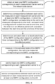
- FIG. 2A is a flowchart illustrating a measurement method according to embodiments of the disclosure. The method is performed by the UE. As illustrated in FIG. 2A , the measurement method may include the following.
- At step 201a at least one SMTC configuration corresponding to each measurement carrier sent by the network side device is received.
- a correspondence between each cell to be measured on each measurement carrier and the at least one SMTC configuration is determined.
- an activated state or a deactivated state of an SMTC configuration is determined.
- step 201a to the step 204a may refer to the description of above embodiments, which are not elaborated in embodiments of the disclosure.
- the UE may obtain the at least one SMTC configuration corresponding to each measurement carrier sent by the network side device, determine the correspondence between each cell to be measured on each measurement carrier and the at least one SMTC configuration, and measure, in the activated state of the SMTC configuration, the cell to be measured corresponding to the SMTC configuration. It may be seen that in embodiments of the disclosure, different cells to be measured on the same measurement carrier are configured with respective SMTC configurations and different SMTC configurations may be activated at different time points to achieve the measurement of different cells to be measured at different time points.
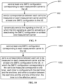
- FIG. 2B is a flowchart illustrating a measurement method according to embodiments of the disclosure. The method is performed by the UE. As illustrated in FIG. 2B , the measurement method may include the following.
- a capability indication is sent to the network side device.
- X may be for example the number of cells to be measured on a same measurement carrier.
- Y may be the number of cells to be measured among all measurement carriers.
- the at least one SMTC configuration corresponding to each measurement carrier sent by the network side device is obtained.
- the number of SMTC configurations corresponding to each measurement carrier may be greater than X. In another embodiment of the disclosure, the number of SMTC configurations corresponding to each measurement carrier may be less than or equal to X.
- the number of SMTC configurations corresponding to each measurement carrier may be greater than Y In another embodiment of the disclosure, the number of SMTC configurations corresponding to each measurement carrier may be less than or equal to Y
- step 203b the correspondence between each cell to be measured on each measurement carrier and the at least one SMTC configuration is determined.
- the number of SMTC configurations corresponding to a certain measurement carrier in the step 202b is greater than X or greater than Y, only a part of the SMTC configurations corresponding to the measurement carrier corresponds to the cells to be measured one by one, while the remaining SMTC configurations do not correspond to any cell to be measured (i.e., the remaining SMTC configurations are not used for measuring the cells).
- the measurement carrier corresponds to four SMTC configurations, namely SMTC#1, SMTC#2, SMTC#3, and SMTC#4.
- SMTC#1 may correspond to the cell 1 to be measured
- SMTC#2 may correspond to the cell 2 to be measured
- SMTC#3 and SMTC#4 do not correspond to any cell to be measured, i.e., SMTC#3 and SMTC#4 are not used for measuring the cells within the carrier.
- step 204b may refer to the description of above embodiments, which is not elaborated in embodiments of the disclosure.
- the UE may obtain the at least one SMTC configuration corresponding to each measurement carrier sent by the network side device, determine the correspondence between each cell to be measured on each measurement carrier and the at least one SMTC configuration, and measure, in the activated state of the SMTC configuration, the cell to be measured corresponding to the SMTC configuration. It may be seen that in embodiments of the disclosure, different cells to be measured on the same measurement carrier are configured with respective SMTC configurations and different SMTC configurations may be activated at different time points to achieve the measurement of different cells to be measured at different time points.
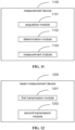
- FIG. 3 is a flowchart illustrating a measurement method according to embodiments of the disclosure. The method is performed by the UE. As illustrated in FIG. 3 , the measurement method may include the following.
- a mobility measurement indication configured, through a Radio Resource Control (RRC) signaling, by the network side device is received.
- RRC Radio Resource Control
- the mobility measurement indication may be configured to instruct the UE to execute a mobility measurement process.
- the at least one configuration SMTC configuration corresponding to each measurement carrier sent by the network side device is obtained.
- step 303 the correspondence between each cell to be measured on each measurement carrier and the at least one SMTC configuration is determined.
- the cell to be measured corresponding to the SMTC configuration is measured in the activated state of the SMTC configuration.
- step 302 may refer to the description of above embodiments, which are not elaborated in embodiments of the disclosure.
- the UE may obtain the at least one SMTC configuration corresponding to each measurement carrier sent by the network side device, determine the correspondence between each cell to be measured on each measurement carrier and the at least one SMTC configuration, and measure, in the activated state of the SMTC configuration, the cell to be measured corresponding to the SMTC configuration. It may be seen that in embodiments of the disclosure, different cells to be measured on the same measurement carrier are configured with respective SMTC configurations, and different SMTC configurations may be activated at different time points to achieve the measurement of different cells to be measured at different time points.
- each cell to be measured may be activated at the corresponding time point based on the transmission delay difference of each satellite, thereby achieving successful measurement of each cell to be measured and solving the problem that "in the NTN system, different neighbor cells to be measured on the same measurement carrier cannot be measured due to different transmission delay differences of corresponding satellites".
- FIG. 4 is a flowchart illustrating a measurement method according to embodiments of the disclosure. The method is performed by the UE. As illustrated in FIG. 4 , the measurement method may include the following.
- the at least one SMTC configuration corresponding to each measurement carrier sent by the network side device is obtained.
- step 402 the correspondence between each cell to be measured on each measurement carrier and the at least one SMTC configuration is determined.
- a first signaling dynamically sent by the network side device is obtained, and the activated state or the deactivated state of the SMTC configuration is determined based on the first signaling.
- the first signaling may be used for activating or deactivating the SMTC configuration(s) on at least one measurement carrier.
- the first signaling may include at least one of the following:
- the measurement carrier CC1 there are four cells to be measured, namely, a cell 1 to be measured, a cell 2 to be measured, a cell 3 to be measured, and a cell 4 to be measured, and the CC1 corresponds to SMTC#1, SMTC#2, SMTC#3, and SMTC#4.
- a time point T1 it is possible to activate the SMTC#1 and the SMTC#3 of CC1, deactivate the SMTC#2 and the SMTC#4 of the CC1, activate the SMTC#1 of the CC2, and deactivate the SMTC#2 of the CC2.
- a time point T2 it is possible to activate the SMTC#2 and the SMTC#3 of the CC1, deactivate the SMTC#1 or the SMTC#4 of the CC1, activate the SMTC#2 of the CC2, and deactivate the SMTC#1 of the CC2.
- the cell to be measured corresponding to the SMTC configuration is measured.
- the cell to be measured corresponding to the SMTC configuration is not measured.
- the UE may measure the cell 1 to be measured and the cell 3 to be measure respectively corresponding to the SMTC#1 and the SMTC#3 in the activated state on the CC1 at the time point T1, and not measure the cell 2 to be measured and the cell 4 to be measured respectively corresponding to the SMTC#2 and the SMTC#4 in the deactivated state on the CC1.
- the measurement may be performed on the cell to be measured corresponding to the SMTC configuration based on the activated state of the SMTC configuration.
- the UE may obtain the at least one SMTC configuration corresponding to each measurement carrier sent by the network side device, and determine the correspondence between each cell to be measured on each measurement carrier and the at least one SMTC configuration, and measure, in the activated state of the SMTC configuration, the cell to be measured corresponding to the SMTC configuration. It may be seen that in embodiments of the disclosure, different cells to be measured on the same measurement carrier are configured with respective SMTC configurations and different SMTC configurations may be activated at different time points to achieve the measurement of different cells to be measured at different time points.
- each cell to be measured may be activated at the corresponding time point based on the transmission delay difference of each satellite, thereby achieving successful measurement of each cell to be measured and solving the problem that "in the NTN system, different neighbor cells to be measured on the same measurement carrier cannot be measured due to different transmission delay differences of corresponding satellites".
- the at least one SMTC configuration corresponding to each measurement carrier sent by the network side device is received.
- each cell to be measured on each measurement carrier and the at least one SMTC configuration is determined, where the SMTC configuration corresponding to the cell to be measured corresponds to one timer, and each timer is configured with a start time and an end time. Between the start time and the end time of the timer, the timer is in an effective period.
- a criteria of determining the start time and the end time for the aforementioned timer is that: within a duration between the start time and the end time of the timer, the reference signal may be received within the cell to be measured corresponding to the SMTC configuration corresponding to the timer, and outside the duration between the start time and the end time of the timer, no reference signal can be received within the cell to be measured corresponding to the SMTC configuration corresponding to the timer.
- the activated state or the deactivated state of the SMTC configuration is determined based on whether the timer corresponding to the SMTC configuration is in the effective period.
- determining the activated state or the deactivated state of the SMTC configuration based on whether the timer corresponding to the SMTC configuration is in the effective period may include:
- the cell to be measured corresponding to the SMTC configuration is measured in the activated state of the SMTC configuration.
- step 501 may refer to the description of above embodiments, which is not elaborated in embodiments of the disclosure.
- the UE may obtain the at least one SMTC configuration corresponding to each measurement carrier sent by the network side device, determine the correspondence between each cell to be measured on each measurement carrier and the at least one SMTC configuration, and measure, in the activated state of the SMTC configuration, the cell to be measured corresponding to the SMTC configuration. It may be seen that in embodiments of the disclosure, different cells to be measured on the same measurement carrier are configured with respective SMTC configurations, and different SMTC configurations may be activated at different time points to achieve the measurement of different cells to be measured at different time points.
- each cell to be measured may be activated at the corresponding time point based on the transmission delay difference of each satellite, thereby achieving successful measurement of each cell to be measured and solving the problem that "in the NTN system, different neighbor cells to be measured on the same measurement carrier cannot be measured due to different transmission delay differences of corresponding satellites".
- FIG. 6 is a flowchart illustrating a measurement method according to embodiments of the disclosure. The method is performed by a network side device. As illustrated in FIG. 6 , the measurement method may include the following.
- At step 601 at least one SMTC configuration corresponding to each measurement carrier is sent to the UE.
- a correspondence between each cell to be measured on each measurement carrier and the at least one SMTC configuration is sent to the UE.
- the SMTC configurations corresponding to different cells to be measured are the same.
- the SMTC configurations corresponding to different cells to be measured are different.
- the UE may obtain the at least one SMTC configuration corresponding to each measurement carrier sent by the network side device, determine the correspondence between each cell to be measured on each measurement carrier and the at least one SMTC configuration, and measure, in the activated state of the SMTC configuration, the cell to be measured corresponding to the SMTC configuration. It may be seen that in embodiments of the disclosure, different cells to be measured on the same measurement carrier are configured with respective SMTC configurations, and different SMTC configurations may be activated at different time points to achieve the measurement of different cells to be measured at different time points.
- each cell to be measured may be activated at the corresponding time point based on the transmission delay difference of each satellite, thereby achieving successful measurement of each cell to be measured and solving the problem that "in the NTN system, different neighbor cells to be measured on the same measurement carrier cannot be measured due to different transmission delay differences of corresponding satellites".
- FIG. 7A is a flowchart illustrating a measurement method according to embodiments of the disclosure. The method is performed the network side device. As illustrated in FIG. 7A , the measurement method may include the following.
- the at least one SMTC configuration corresponding to each measurement carrier is sent to the UE.
- step 702a the correspondence between each cell to be measured on each measurement carrier and the at least one SMTC configuration is sent to the UE.
- the activated state or the deactivated state for the SMTC configuration is indicated to the UE.
- the UE is able to obtain the measurement signal of the cell to be measured corresponding to the SMTC configuration in response to the SMTC configuration being in the activated state.
- step 701a to thee step 703a may refer to the description of above embodiments, which are not elaborated in embodiments of the disclosure.
- the UE may obtain the at least one SMTC configuration corresponding to each measurement carrier sent by the network side device, determine the correspondence between each cell to be measured on each measurement carrier and the at least one SMTC configuration, and measure, in the activated state of the SMTC configuration, the cell to be measured corresponding to the SMTC configuration. It may be seen that in embodiments of the disclosure, different cells to be measured on the same measurement carrier are configured with respective SMTC configurations, and different SMTC configurations may be activated at different time points to achieve the measurement of different cells to be measured at different time points.
- each cell to be measured may be activated at the corresponding time point based on the transmission delay difference of each satellite, thereby achieving successful measurement of each cell to be measured and solving the problem that "in the NTN system, different neighbor cells to be measured on the same measurement carrier cannot be measured due to different transmission delay differences of corresponding satellites".
- FIG.7B is a flowchart illustrating a measurement method according to embodiments of the disclosure. The method is performed by the network side device. As illustrated in FIG. 7B , the measurement method may include the following.
- a capability indication sent by the UE is received.
- the capability indication may include at least one of the following:
- At step 702b at least one SMTC configuration corresponding to each measurement carrier is sent to the UE.
- step 703b the correspondence between each cell to be measured on each measurement carrier and the at least one SMTC configuration is sent to the UE.
- step 701b to the step 703b may refer to the description of above embodiments, which are not elaborated in embodiments of the disclosure.
- the UE may obtain the at least one SMTC configuration corresponding to each measurement carrier sent by the network side device, determine the correspondence between each cell to be measured on each measurement carrier and the at least one SMTC configuration, and measure, in the activated state of the SMTC configuration, the cell to be measured corresponding to the SMTC configuration. It may be seen that in embodiments of the disclosure, different cells to be measured on the same measurement carrier are configured with respective SMTC configurations, and different SMTC configurations may be activated at different time points to achieve the measurement of different cells to be measured at different time points.
- each cell to be measured may be activated at the corresponding time point based on the transmission delay difference of each satellite, thereby achieving successful measurement of each cell to be measured and solving the problem that "in the NTN system, different neighbor cells to be measured on the same measurement carrier cannot be measured due to different transmission delay differences of corresponding satellites".
- FIG. 8 is a flowchart illustrating a measurement method according to embodiments of the disclosure. The method is performed by the network side device. As illustrated in FIG. 8 , the measurement method may include the following.
- a mobility measurement indication is configured to the UE through an RRC signaling.
- the at least one SMTC configuration corresponding to each measurement carrier is sent to the UE.
- step 803 the correspondence between each cell to be measured on each measurement carrier and the at least one SMTC configuration is sent to the UE.
- the UE may obtain the at least one SMTC configuration corresponding to each measurement carrier sent by the network side device, determine the correspondence between each cell to be measured on each measurement carrier and the at least one SMTC configuration, and measure, in the activated state of the SMTC configuration, the cell to be measured corresponding to the SMTC configuration. It may be seen that in embodiments of the disclosure, different cells to be measured on the same measurement carrier are configured with respective SMTC configurations, and different SMTC configurations may be activated at different time points to achieve the measurement of different cells to be measured at different time points.
- each cell to be measured may be activated at the corresponding time point based on the transmission delay difference of each satellite, thereby achieving successful measurement of each cell to be measured and solving the problem that "in the NTN system, different neighbor cells to be measured on the same measurement carrier cannot be measured due to different transmission delay differences of corresponding satellites".
- FIG. 9 is a flowchart illustrating a measurement method according to embodiments of the disclosure. The method is performed by a network side device. As illustrated in FIG. 9 , the measurement method may include the following.
- At step 901 at least one SMTC configuration corresponding to each measurement carrier is sent to the UE.
- step 902 the correspondence between each cell to be measured on each measurement carrier and the at least one SMTC configuration is sent to the UE.
- a first signaling is dynamically sent to the UE, in which the first signaling is used for activating or deactivating the SMTC configuration on at least one measurement carrier.
- the first signaling may include at least one of the following:
- the UE may obtain the at least one SMTC configuration corresponding to each measurement carrier sent by the network side device, determine the correspondence between each cell to be measured on each measurement carrier and the at least one SMTC configuration, and measure, in the activated state of the SMTC configuration, the cell to be measured corresponding to the SMTC configuration. It may be seen that in embodiments of the disclosure, different cells to be measured on the same measurement carrier are configured with respective SMTC configurations, and different SMTC configurations may be activated at different time points to achieve the measurement of different cells to be measured at different time points.
- each cell to be measured may be activated at the corresponding time point based on the transmission delay difference of each satellite, thereby achieving successful measurement of each cell to be measured and solving the problem that "in the NTN system, different neighbor cells to be measured on the same measurement carrier cannot be measured due to different transmission delay differences of corresponding satellites".
- FIG. 10 is a flowchart illustrating a measurement method according to embodiments of the disclosure. The method is performed by the network side device. As illustrated in FIG. 10 , the measurement method may include the following.
- At step 1001 at least one SMTC configuration corresponding to each measurement carrier is sent to the UE.
- the correspondence between each cell to be measured on each measurement carrier and the at least one SMTC configuration is sent to the UE, in which the SMTC configuration corresponding to the cell to be measured corresponds to one timer, each timer is configured with the start time and the end time, and within a duration between the start time and the end time of the timer, the timer is in the effective period.
- an SMTC configuration corresponds to one timer, and each timer is configured with the start time and the end time. With the duration between the start time and the end time of the timer, the timer is in the effective period.
- the UE may obtain the at least one SMTC configuration corresponding to each measurement carrier sent by the network side device, determine the correspondence between each cell to be measured on each measurement carrier and the at least one SMTC configuration, and measure, in the activated state of the SMTC configuration, the cell to be measured corresponding to the SMTC configuration. It may be seen that in embodiments of the disclosure, different cells to be measured on the same measurement carrier are configured with respective SMTC configurations, and different SMTC configurations may be activated at different time points to achieve the measurement of different cells to be measured at different time points.
- each cell to be measured can be activated at the corresponding time point based on the transmission delay difference of each satellite, thereby achieving successful measurement of each cell to be measured and solving the problem that "in the NTN system, different neighbor cells to be measured on the same measurement carrier cannot be measured due to different transmission delay differences of corresponding satellites".
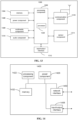
- FIG. 11 is a schematic diagram illustrating a measurement device according to embodiments of the disclosure.
- the device is configured in the UE.
- the measurement device may include an acquisition module, a determination module and a measurement module.
- the acquisition module is configured to obtain at least one SMTC configuration corresponding to each measurement carrier sent by the network side device.
- the determination module is configured to determine a correspondence between each cell to be measured on each measurement carrier and the at least one SMTC configuration.
- the measurement module is configured to measure, in an activated state of an SMTC configuration, a cell to be measured corresponding to the SMTC configuration.
- the UE may obtain the at least one SMTC configuration corresponding to each measurement carrier sent by the network side device, determine the correspondence between each cell to be measured on each measurement carrier and the at least one SMTC configuration, and measure, in the activated state of the SMTC configuration, the cell to be measured corresponding to the SMTC configuration. It may be seen that in embodiments of the disclosure, different cells to be measured on the same measurement carrier are configured with respective SMTC configurations, and different SMTC configurations may be activated at different time points to achieve the measurement of different cells to be measured at different time points.
- each cell to be measured may be activated at the corresponding time point based on the transmission delay difference of each satellite, thereby achieving successful measurement of each cell to be measured and solving the problem that "in the NTN system, different neighbor cells to be measured on the same measurement carrier cannot be measured due to different transmission delay differences of corresponding satellites".
- the device is further configured to: determine an activated state or a deactivated state of the SMTC configuration.
- the device is further configured to: send a capability indication to the network side device, in which the capability indication includes at least one of the following:
- the device is further configured to: receive the mobility measurement indication configured, through a RRC signaling, by the network side device.
- SMTC configurations corresponding to different cells to be measured are the same.
- SMTC configurations corresponding to different cells to be measured are different.
- the device is further configured to: obtain a first signaling dynamically sent by the network side device, and determine the activated state or the deactivated state of the SMTC configuration based on the first signaling; in which the first signaling is used for activating or deactivating the SMTC configuration on at least one measurement carrier.
- the first signaling includes at least one of the following:
- the SMTC configuration corresponds to one timer, each timer configured with the start time and the end time. With a duration between the start time and the end time of the timer, the timer is in the effective period.
- the determination module is further configured to: determine the activated state or the deactivated state of the SMTC configuration based on whether the timer corresponding to the SMTC configuration is in the effective period.
- the determination module is further configured to:
- the UE is able to successfully obtain the measurement signal of the cell to be measured corresponding to the SMTC configuration in response to the SMTC configuration being in the activated state.
- FIG. 12 is a schematic diagram illustrating a measurement device according to embodiments of the disclosure.
- the device is configured in the network side device.
- the measurement device may include a first transmission module and a second transmission module.
- the first transmission module is configured to send at least one SMTC configuration corresponding to each measurement carrier to the UE.
- the second transmission module is configured to send a correspondence between each cell to be measured on each measurement carrier and the at least one SMTC configuration to the UE.
- the UE may obtain the at least one SMTC configuration corresponding to each measurement carrier sent by the network side device, determine the correspondence between each cell to be measured on each measurement carrier and the at least one SMTC configuration, and measure, in the activated state of the SMTC configuration, the cell to be measured corresponding to the SMTC configuration. It may be seen that in embodiments of the disclosure, different cells to be measured on the same measurement carrier are configured with respective SMTC configurations, and different SMTC configurations will be activated at different time points to achieve the measurement of different cells to be measured at different time points.
- each cell to be measured may be activated at the corresponding time point based on the transmission delay difference of each satellite, thereby achieving successful measurement of each cell to be measured and solving the problem that "in the NTN system, different neighbor cells to be measured on the same measurement carrier cannot be measured due to different transmission delay differences of corresponding satellites".
- the device is further configured to: indicate to the UE an activated state or a deactivated state for the SMTC configuration.
- the device is further configured to: obtain a capability indication sent by the UE; in which the capability indication includes at least one of the following:
- the device is further configured to: configure a mobility measurement indication to the UE through a RRC signaling.
- SMTC configurations corresponding to different cells to be measured are the same.
- SMTC configurations corresponding to different cells to be measured are different.
- the indication module is further configured to: dynamically send a first signaling to the UE, in which the first signaling is used for activating or deactivating the SMTC configuration on at least one measurement carrier.
- the first signaling includes at least one of the following:
- the SMTC configuration corresponds to one timer, and each timer is configured with the start time and the end time. Within a duration between the start time and the end time of the timer, the timer is in the effective period.
- the UE is able to obtain the measurement signal of the cell to be measured corresponding to the SMTC configuration in response to the SMTC configuration being in the activated state.
- FIG. 13 is a block diagram illustrating a user equipment (UE) 1300 according to an embodiment of the disclosure.
- the UE 1300 may be a mobile phone, a computer, a digital broadcasting terminal, a message sending and receiving apparatus, a game console, a tablet apparatus, a medical apparatus, a fitness apparatus, a personal digital assistant, etc.
- the UE 1300 may include one or more of following components: a processing component 1302, a memory 1304, a power component 1306, a multimedia component 1308, an audio component 1310, an input/output (I/O) interface 1312, a sensor component 1313 and a communication component 1316.
- a processing component 1302 a memory 1304, a power component 1306, a multimedia component 1308, an audio component 1310, an input/output (I/O) interface 1312, a sensor component 1313 and a communication component 1316.
- the processing component 1302 typically controls the overall operation of the UE 1300, such as operations associated with display, telephone calls, data communication, camera operations, and recording operations.
- the processing component 1302 may include one or more processors 1320 to execute instructions to complete all or part of the steps of the above methods.
- the processing component 1302 may include one or more modules to facilitate the interaction between the processing component 1302 and other components.
- the processing component 1302 may include a multimedia module to facilitate interaction between the multimedia component 1308 and the processing component 1302.
- the memory 1304 is configured to store various types of data to support operations on the UE 1300. Examples of these data include instructions for any application program or method operated on the UE 1300, contact data, phone book data, messages, images, videos, etc.
- the memory 1304 may be implemented by any type of volatile or non-volatile storage apparatus or a combination thereof, such as a static random access memory (SRAM), an electrically erasable programmable read-only memory (EEPROM), an erasable programmable read-only memory (EPROM), a programmable read-only memory (PROM), a read-only memory (ROM), a magnetic memory, a flash memory, a magnetic disk or an optical disc.
- SRAM static random access memory
- EEPROM electrically erasable programmable read-only memory
- EPROM erasable programmable read-only memory
- PROM programmable read-only memory
- ROM read-only memory
- magnetic memory a magnetic memory
- flash memory a flash memory
- the power component 1306 provides power to various components of the UE1300.
- the power component 1306 may include a power management system, at least one power supply, and other components associated with generating, managing, and distributing power for the UE 1300.
- the multimedia component 1308 includes a screen providing an output interface between the UE 1300 and a user.
- the screen may include a liquid crystal display (LCD) and a touch panel (TP). If the screen includes the touch panel, the screen may be implemented as a touch screen to receive input signals from the user.
- the touch panel includes at least one touch sensor to sense touches, slides and gestures on the touch panel. The touch sensor may not only sense the boundaries of the touch or slide action, but also detect the wake-up time and pressure associated with the touch or slide operation.
- the multimedia component 1308 includes a front-facing camera and/or a rear-facing camera.
- the front-facing camera and/or the rear-facing camera may receive external multimedia data when the UE 1300 is in an operating mode, such as a shooting mode or a video mode.
- Each front-facing camera and rear-facing camera may be a fixed optical lens system or have a focal length and an optical zoom capability.
- the audio component 1310 is configured to output and/or input audio signals.
- the audio component 1310 includes a microphone (MIC) that is configured to receive external audio signals when the UE 1300 is in the operating mode, such as a call mode, a recording mode, and a speech recognition mode.
- the received audio signals may be further stored in the memory 1304 or transmitted through the communication component 1316.
- the audio component 1310 further includes a speaker for outputting the audio signals.
- the Input/output (I/O) interface 1312 provides an interface between the processing component 1302 and a peripheral interface module.
- the peripheral interface module may be a keypad, a click wheel, a button, and the like. These buttons may include, but are not limited to, a home button, a volume button, a start button, and a lock button.
- the sensor component 1313 includes at least one sensor for providing state assessments of various aspects for the UE 1300.
- the sensor component 1313 may detect the on/off state of the UE 1300, the relative positioning of components, such as a display and a keypad of the UE 1300.
- the sensor component 1313 may also detect the position change of the UE 1300 or a component of the UE 1300, the presence or absence of user contact with the UE 1300, the orientation or acceleration/deceleration of the UE 1300 and the temperature change of the UE 1300.
- the sensor component 1313 may include a proximity sensor configured to detect the presence of a nearby object without any physical contact.
- the sensor component 1313 may also include an optical sensor, such as a CMOS or CCD image sensor, for use in imaging applications.
- the sensor component 1313 may also include an acceleration sensor, a gyroscope sensor, a magnetic sensor, a pressure sensor, or a temperature sensor.
- the communication component 1316 is configured to facilitate wired or wireless communication between the UE 1300 and other apparatuses.
- the UE 1300 may access to a wireless network based on a communication standard, such as Wi-Fi, 2G or 3G, or a combination thereof.
- the communication component 1316 receives broadcast signals or broadcast-related information from an external broadcast management system via a broadcast channel.
- the communication component 1316 further includes a near field communication (NFC) module to facilitate short range communication.
- NFC modules may be implemented based on Radio Frequency Identification (RFID) technology, Infrared Data Association (IrDA) technology, Ultra Wide Band (UWB) technology, Bluetooth (BT) technology and other technologies.
- RFID Radio Frequency Identification
- IrDA Infrared Data Association
- UWB Ultra Wide Band
- Bluetooth Bluetooth
- the UE 1300 may be implemented by at least one application specific integrated circuit (ASIC), digital signal processor (DSP), digital signal processing device (DSPD), programmable logic device (PLD), field programmable gate array (FPGA), controller, microcontroller, microprocessor, or another electronic element, for executing the above methods.
- ASIC application specific integrated circuit
- DSP digital signal processor
- DSPD digital signal processing device
- PLD programmable logic device
- FPGA field programmable gate array
- controller microcontroller, microprocessor, or another electronic element, for executing the above methods.
- FIG. 14 is a block diagram illustrating a network side device 1400 according to embodiments of the disclosure.
- the network side device 1400 may be provided as a network side device.
- the network side device 1400 includes a processing component 1411, which further includes at least one processor, and a memory resource represented by a memory 1432, in which the memory resource is configured for storing instructions that can be executed by the processing component 1422, such as an application program.
- the application programs stored in the memory 1432 may include one or more modules, with each module corresponding to a set of instructions.
- the processing component 1410 is configured to execute instructions to execute any of aforementioned methods performed by the network side device, such as the method illustrated in FIG. 1A and FIG. 1B .
- the network side device 1400 may also include a power component 1426 configured to execute power management of the network side device 1400, a wired or wireless network interface 1450 configured to connect the network side device 1400 to the network, and an input/output (I/O) interface 1458.
- the network side device 1400 may operate an operating system storage in the memory 1432, such as Windows Server TM, Mac OS XTM, Unix TM, Linux TM, Free BSDTM or similar.
- the methods according to embodiments of the disclosure are introduced respectively from the perspective of the network side device and the UE.
- the network side device and the UE may include a hardware structure and a software module, to achieve the above functions in a form of the hardware structure, the software module, or the hardware structure plus the software module.
- One of the above functions may be executed in the form of the hardware structure, the software module, or the hardware structure plus the software module.
- the communication device may include a transceiver module and a processing module.
- the transceiver module may include a transmission module and/or a receiving module.
- the transmission module is configured to implement a transmission function
- the receiving module is configured to implement a receiving function
- the transceiver module may implement the transmission function and/or the receiving function.
- the communication device may be a terminal device (such as the terminal device in aforementioned method embodiments), a device within the terminal device, or a device that may be matched and used with the terminal device.
- the communication device may be a network device, a device within a network device, or a device that may be matched and used with the network device.
- the communication device may be a network device, a terminal device (such as the terminal device in aforementioned method embodiments), or may be a chip, a chip system, or a processor that supports the network device to implement the above methods, or may be a chip, a chip system, or a processor that supports the terminal device to implement the above methods.
- This device may be configured to implement the methods described in the above method embodiments, as described in e above method embodiments.
- the communication device may include one or more processors.
- the processor may be a general-purpose processor or a dedicated processor, etc.
- the processor may be a baseband processor or a central processor.
- the baseband processor may be configured to process communication protocols and data
- the central processor may be configured to control the communication device (such as the network side device, a baseband chip, a terminal device, a terminal device chip, a DU or a CU. etc.), execute a computer program, and process data from the computer program.
- the communication device may also include one or more memories on which the computer program is stored, and the processor executes the computer program to enable the communication device to execute the methods described in above embodiments.
- the memory may also store data. The communication device and the memory may be provided separately or integrated together.
- the communication device may also include a transceiver and an antenna.
- the transceiver may be referred to as a transceiver unit, a transceiver machine, or a transceiver circuit, etc., and the transceiver is configured to achieve a transceiver function.
- the transceiver may include a receiver and a transmitter, the receiver may be referred to as a receiver machine or a receiving circuit, etc., to achieve a receiving function, and the transmitter may be referred to as a transmitter machine or a transmission circuit, etc., to achieve a transmission function.
- the communication device may also include one or more interface circuits.
- the interface circuit is configured to receive code instructions and transmit the code instructions to the processor.
- the processor runs the code instructions to enable the communication device to execute the methods described in above method embodiments.
- the communication device is the terminal device (such as the terminal device in aforementioned method embodiments).
- the processor is configured to execute any of the methods illustrated in FIGS. 1A to 4 .
- the communication device is the network device.
- the transceiver is configured to execute any of the methods illustrated in FIGS. 5 to 7B .
- the processor may include the transceiver for implementing the receiving function and the transmission function.
- the transceiver may be the transceiver circuit, an interface, or an interface circuit.
- the transceiver circuit, the interface, or the interface circuit configured to achieve the receiving function and the transmission function may be separate or integrated together.
- the above-mentioned transceiver circuit, the interface, or the interface circuit may be configured for reading and writing code/data, or the above-mentioned transceiver circuit, the interface, or the interface circuit may be configured for transmitting or transferring signals.
- the processor may store the computer program.
- the communication device is caused to execute the methods described in above embodiments.
- the computer program may be embedded in the processor, in which case the processors may be implemented by a hardware.
- the communication device may include a circuit that may achieve the functions of transmission, receiving, or communicating as described in aforementioned method embodiments.
- the processor and the transceiver described in the present disclosure may be implemented in an integrated circuit (IC), an analog IC, a RF integrated circuit (RFIC), a mixed signal IC, an application specific integrated circuit (ASIC), a printed circuit board (PCB), or an electronic device, etc.
- the processor and the transceiver may also be manufactured using various IC process technologies, such as complementary metal oxide semiconductor (CMOS), nMetal-oxide-semiconductor (NMOS), positive channel metal oxide semiconductor (PMOS), bipolar junction transistor (BJT), bipolar CMOS (BiCMOS), silicon germanium (SiGe), gallium arsenide (GaAs), etc.
- CMOS complementary metal oxide semiconductor
- NMOS nMetal-oxide-semiconductor
- PMOS positive channel metal oxide semiconductor
- BJT bipolar junction transistor
- BiCMOS bipolar CMOS
- SiGe silicon germanium
- GaAs gallium arsenide
- the communication device described in above embodiments may be the network device or the terminal device (such as the terminal device in aforementioned method embodiments), but the scope of the communication device described in the disclosure is not limited to this, and the structure of the communication device may be unrestricted.
- the communication device may be an independent device or part of a larger device.
- the communication device may be:
- the chip includes the processor and the interface.
- the number of processors may be one or more, and the number of interfaces may be multiple.
- the chip also includes the memory, in which the memory is configured to store necessary computer programs and data.
- Embodiments of the disclosure also provides a system for determining a duration of sidelink, in which the system includes the communication device as the terminal device (such as the first terminal device in aforementioned method embodiments) and the communication device as the network device in the aforementioned embodiments, or the system includes the communication device as the terminal device (such as the first terminal device in aforementioned method embodiments) and the communication device as the network device in aforementioned embodiments.
- the disclosure also provides a readable storage medium having instructions stored thereon. When the instructions are executed, functions of any of above method embodiments are implemented.
- the disclosure also provides a computer program product that, when executed by the computer, implements functions of any of above method embodiments.
- inventions may be fully or partially implemented through software, hardware, firmware, or any combination thereof.
- embodiments may be fully or partially implemented in the form of computer program products.
- the computer program product includes one or more computer programs. When loading and executing the computer program on the computer, all or part of the processes or functions described in embodiments of the disclosure are generated.
- the computer may be a general-purpose computer, a specialized computer, a computer network, or other programmable devices.
- the computer program may be stored in a computer-readable storage medium or transmitted from one computer-readable storage medium to another.
- the computer program may be transmitted from a website site, a computer, a server, or a data center via wired (such as a coaxial cable, an optical fiber, a digital subscriber line (DSL)) or wireless (such as infrared, wireless, microwave, etc.) methods to another website site, computer, server, or data center.
- the computer-readable storage medium may be any available medium that the computer may access, or a data storage device such as a server, a data center, etc. that integrates one or more available medium.
- the available medium may be a magnetic medium (such as a floppy disk, a hard disk, a magnetic tape), an optical medium (such as a high-density digital video discs (DVD)), or a semiconductor medium (such as a solid state disk (SSD)), etc.
- a magnetic medium such as a floppy disk, a hard disk, a magnetic tape
- an optical medium such as a high-density digital video discs (DVD)
- DVD high-density digital video discs
- SSD solid state disk
- first, second, and other numerical numbers involved in the disclosure are only for a convenience of description and differentiation, and are not used to limit the scope of embodiments of the disclosure, but also indicate an order.
- the term “at least one” in the disclosure may also be described as one or a plurality of, and the term “a/the plurality of” may be two, three, four, or more, which is not limited in the disclosure.
- technical features in the technical feature are distinguished by “first”, “second”, “third”, “A”, “B”, “C”, and “D”, and there is no order or order of magnitude between the technical features described in “first”, “second”, “third”, “A”, “B”, “C”, and “D”.
Landscapes
- Engineering & Computer Science (AREA)
- Computer Networks & Wireless Communication (AREA)
- Signal Processing (AREA)
- Physics & Mathematics (AREA)
- Astronomy & Astrophysics (AREA)
- Aviation & Aerospace Engineering (AREA)
- General Physics & Mathematics (AREA)
- Mobile Radio Communication Systems (AREA)
Applications Claiming Priority (1)
| Application Number | Priority Date | Filing Date | Title |
|---|---|---|---|
| PCT/CN2021/137607 WO2023108374A1 (zh) | 2021-12-13 | 2021-12-13 | 一种测量方法/装置/用户设备/网络侧设备及存储介质 |
Publications (2)
| Publication Number | Publication Date |
|---|---|
| EP4451730A1 true EP4451730A1 (de) | 2024-10-23 |
| EP4451730A4 EP4451730A4 (de) | 2025-10-15 |
Family
ID=86774924
Family Applications (1)
| Application Number | Title | Priority Date | Filing Date |
|---|---|---|---|
| EP21967516.2A Pending EP4451730A4 (de) | 2021-12-13 | 2021-12-13 | Messverfahren und -vorrichtung, benutzergerät, netzwerkseitige ausrüstung und speichermedium |
Country Status (3)
| Country | Link |
|---|---|
| EP (1) | EP4451730A4 (de) |
| CN (1) | CN116982337A (de) |
| WO (1) | WO2023108374A1 (de) |
Family Cites Families (4)
| Publication number | Priority date | Publication date | Assignee | Title |
|---|---|---|---|---|
| CN109391960B (zh) * | 2017-08-11 | 2023-04-25 | 北京紫光展锐通信技术有限公司 | 测量配置方法、基站及计算机可读存储介质 |
| CN111585724B (zh) * | 2019-02-15 | 2023-06-27 | 华为技术有限公司 | 通信方法、装置及设备 |
| CN112312451B (zh) * | 2019-07-29 | 2022-10-28 | 大唐移动通信设备有限公司 | 一种测量同步的方法、网络设备及终端设备 |
| CN113347697A (zh) * | 2020-02-18 | 2021-09-03 | 华为技术有限公司 | 更新定时偏移量的方法及装置 |
-
2021
- 2021-12-13 CN CN202180004524.6A patent/CN116982337A/zh active Pending
- 2021-12-13 WO PCT/CN2021/137607 patent/WO2023108374A1/zh not_active Ceased
- 2021-12-13 EP EP21967516.2A patent/EP4451730A4/de active Pending
Also Published As
| Publication number | Publication date |
|---|---|
| CN116982337A (zh) | 2023-10-31 |
| EP4451730A4 (de) | 2025-10-15 |
| WO2023108374A1 (zh) | 2023-06-22 |
Similar Documents
| Publication | Publication Date | Title |
|---|---|---|
| EP4557775A1 (de) | Verfahren und vorrichtung zur bestimmung einer positionierungsunterstützten endgerätevorrichtung | |
| US20250324308A1 (en) | Reporting method and apparatus | |
| US20250274820A1 (en) | Methods and apparatuses for recording report of successful pscell addition or change | |
| US20260019209A1 (en) | Sl prs configuration negotiation method and apparatus | |
| US20250280316A1 (en) | Measurement report sending method and apparatus, and measurement report receiving method and apparatus | |
| US20250287274A1 (en) | Method and apparatus for recording location information for report of successful pscell addition or change | |
| EP4518425A1 (de) | Verfahren zur aufzeichnung relevanter informationen und vorrichtung für erfolgreichen pscell-hinzufügungs- oder -ersatzbericht | |
| US20250097967A1 (en) | Signal receiving method and apparatus, user equipment, base station, and storage medium | |
| US20250141648A1 (en) | Method and device for receiving temporary reference signal | |
| US20250097839A1 (en) | Measurement relaxtion method, device apparatus, storage medium and apparatus | |
| US20250151013A1 (en) | Positioning method, apparatus, device, and storage medium | |
| JP7733830B2 (ja) | ランダムアクセスリソース設定の決定方法及びデバイス/記憶媒体/装置 | |
| EP4518426A1 (de) | Verhandlungsverfahren, -vorrichtung und -vorrichtung sowie speichermedium | |
| EP4451730A1 (de) | Messverfahren und -vorrichtung, benutzergerät, netzwerkseitige ausrüstung und speichermedium | |
| US20250038792A1 (en) | Precoding method and apparatus, user equipment, ris array, base station and storage medium | |
| US20240365368A1 (en) | Service control method and apparatus, user equipment, base station, and storage medium | |
| RU2835862C2 (ru) | Способ и устройство для приема сигнала, пользовательское оборудование, базовая станция и носитель данных | |
| RU2835862C9 (ru) | Способ и устройство для приема сигнала, пользовательское оборудование, базовая станция и носитель данных | |
| RU2838058C2 (ru) | Способ и устройство для обновления информации | |
| US20250287261A1 (en) | Cell management methods and user equipment | |
| US20250097742A1 (en) | Measurement relaxation method and apparatus, storage medium, and device | |
| RU2842017C2 (ru) | Способ и устройство для определения порога для бесконкурентного произвольного доступа (CFRA), носитель данных и устройство связи | |
| US20250227641A1 (en) | Method for timing adjustment, communication apparatus and non-transitory computer-readable storage medium | |
| US20250063546A1 (en) | Mapping mode determination method/apparatus/device and storage medium | |
| US20250015880A1 (en) | Information updating method and apparatus, user equipment, base station, and storage medium |
Legal Events
| Date | Code | Title | Description |
|---|---|---|---|
| STAA | Information on the status of an ep patent application or granted ep patent |
Free format text: STATUS: THE INTERNATIONAL PUBLICATION HAS BEEN MADE |
|
| PUAI | Public reference made under article 153(3) epc to a published international application that has entered the european phase |
Free format text: ORIGINAL CODE: 0009012 |
|
| STAA | Information on the status of an ep patent application or granted ep patent |
Free format text: STATUS: REQUEST FOR EXAMINATION WAS MADE |
|
| 17P | Request for examination filed |
Effective date: 20240710 |
|
| AK | Designated contracting states |
Kind code of ref document: A1 Designated state(s): AL AT BE BG CH CY CZ DE DK EE ES FI FR GB GR HR HU IE IS IT LI LT LU LV MC MK MT NL NO PL PT RO RS SE SI SK SM TR |
|
| DAV | Request for validation of the european patent (deleted) | ||
| DAX | Request for extension of the european patent (deleted) | ||
| A4 | Supplementary search report drawn up and despatched |
Effective date: 20250916 |
|
| RIC1 | Information provided on ipc code assigned before grant |
Ipc: H04W 24/08 20090101AFI20250910BHEP Ipc: H04W 24/10 20090101ALI20250910BHEP Ipc: H04B 7/185 20060101ALI20250910BHEP |