EP4451477B1 - Verbinderanordnung, kleidungsstück und elektrische vorrichtung mit pad - Google Patents
Verbinderanordnung, kleidungsstück und elektrische vorrichtung mit pad Download PDFInfo
- Publication number
- EP4451477B1 EP4451477B1 EP24160354.7A EP24160354A EP4451477B1 EP 4451477 B1 EP4451477 B1 EP 4451477B1 EP 24160354 A EP24160354 A EP 24160354A EP 4451477 B1 EP4451477 B1 EP 4451477B1
- Authority
- EP
- European Patent Office
- Prior art keywords
- base body
- garment
- connector
- tag portion
- base
- Prior art date
- Legal status (The legal status is an assumption and is not a legal conclusion. Google has not performed a legal analysis and makes no representation as to the accuracy of the status listed.)
- Active
Links
Images


Classifications
-
- H—ELECTRICITY
- H01—ELECTRIC ELEMENTS
- H01R—ELECTRICALLY-CONDUCTIVE CONNECTIONS; STRUCTURAL ASSOCIATIONS OF A PLURALITY OF MUTUALLY-INSULATED ELECTRICAL CONNECTING ELEMENTS; COUPLING DEVICES; CURRENT COLLECTORS
- H01R12/00—Structural associations of a plurality of mutually-insulated electrical connecting elements, specially adapted for printed circuits, e.g. printed circuit boards [PCB], flat or ribbon cables, or like generally planar structures, e.g. terminal strips, terminal blocks; Coupling devices specially adapted for printed circuits, flat or ribbon cables, or like generally planar structures; Terminals specially adapted for contact with, or insertion into, printed circuits, flat or ribbon cables, or like generally planar structures
- H01R12/70—Coupling devices
- H01R12/77—Coupling devices for flexible printed circuits, flat or ribbon cables or like structures
-
- H—ELECTRICITY
- H01—ELECTRIC ELEMENTS
- H01R—ELECTRICALLY-CONDUCTIVE CONNECTIONS; STRUCTURAL ASSOCIATIONS OF A PLURALITY OF MUTUALLY-INSULATED ELECTRICAL CONNECTING ELEMENTS; COUPLING DEVICES; CURRENT COLLECTORS
- H01R12/00—Structural associations of a plurality of mutually-insulated electrical connecting elements, specially adapted for printed circuits, e.g. printed circuit boards [PCB], flat or ribbon cables, or like generally planar structures, e.g. terminal strips, terminal blocks; Coupling devices specially adapted for printed circuits, flat or ribbon cables, or like generally planar structures; Terminals specially adapted for contact with, or insertion into, printed circuits, flat or ribbon cables, or like generally planar structures
- H01R12/50—Fixed connections
- H01R12/59—Fixed connections for flexible printed circuits, flat or ribbon cables or like structures
- H01R12/592—Fixed connections for flexible printed circuits, flat or ribbon cables or like structures connections to contact elements
-
- H—ELECTRICITY
- H01—ELECTRIC ELEMENTS
- H01R—ELECTRICALLY-CONDUCTIVE CONNECTIONS; STRUCTURAL ASSOCIATIONS OF A PLURALITY OF MUTUALLY-INSULATED ELECTRICAL CONNECTING ELEMENTS; COUPLING DEVICES; CURRENT COLLECTORS
- H01R12/00—Structural associations of a plurality of mutually-insulated electrical connecting elements, specially adapted for printed circuits, e.g. printed circuit boards [PCB], flat or ribbon cables, or like generally planar structures, e.g. terminal strips, terminal blocks; Coupling devices specially adapted for printed circuits, flat or ribbon cables, or like generally planar structures; Terminals specially adapted for contact with, or insertion into, printed circuits, flat or ribbon cables, or like generally planar structures
- H01R12/70—Coupling devices
- H01R12/77—Coupling devices for flexible printed circuits, flat or ribbon cables or like structures
- H01R12/778—Coupling parts carrying sockets, clips or analogous counter-contacts
-
- A—HUMAN NECESSITIES
- A41—WEARING APPAREL
- A41D—OUTERWEAR; PROTECTIVE GARMENTS; ACCESSORIES
- A41D1/00—Garments
- A41D1/002—Garments adapted to accommodate electronic equipment
- A41D1/005—Garments adapted to accommodate electronic equipment with embedded cable or connector
-
- H—ELECTRICITY
- H01—ELECTRIC ELEMENTS
- H01R—ELECTRICALLY-CONDUCTIVE CONNECTIONS; STRUCTURAL ASSOCIATIONS OF A PLURALITY OF MUTUALLY-INSULATED ELECTRICAL CONNECTING ELEMENTS; COUPLING DEVICES; CURRENT COLLECTORS
- H01R12/00—Structural associations of a plurality of mutually-insulated electrical connecting elements, specially adapted for printed circuits, e.g. printed circuit boards [PCB], flat or ribbon cables, or like generally planar structures, e.g. terminal strips, terminal blocks; Coupling devices specially adapted for printed circuits, flat or ribbon cables, or like generally planar structures; Terminals specially adapted for contact with, or insertion into, printed circuits, flat or ribbon cables, or like generally planar structures
- H01R12/70—Coupling devices
- H01R12/7005—Guiding, mounting, polarizing or locking means; Extractors
- H01R12/7011—Locking or fixing a connector to a PCB
-
- H—ELECTRICITY
- H01—ELECTRIC ELEMENTS
- H01R—ELECTRICALLY-CONDUCTIVE CONNECTIONS; STRUCTURAL ASSOCIATIONS OF A PLURALITY OF MUTUALLY-INSULATED ELECTRICAL CONNECTING ELEMENTS; COUPLING DEVICES; CURRENT COLLECTORS
- H01R12/00—Structural associations of a plurality of mutually-insulated electrical connecting elements, specially adapted for printed circuits, e.g. printed circuit boards [PCB], flat or ribbon cables, or like generally planar structures, e.g. terminal strips, terminal blocks; Coupling devices specially adapted for printed circuits, flat or ribbon cables, or like generally planar structures; Terminals specially adapted for contact with, or insertion into, printed circuits, flat or ribbon cables, or like generally planar structures
- H01R12/70—Coupling devices
- H01R12/77—Coupling devices for flexible printed circuits, flat or ribbon cables or like structures
- H01R12/771—Details
-
- H—ELECTRICITY
- H01—ELECTRIC ELEMENTS
- H01R—ELECTRICALLY-CONDUCTIVE CONNECTIONS; STRUCTURAL ASSOCIATIONS OF A PLURALITY OF MUTUALLY-INSULATED ELECTRICAL CONNECTING ELEMENTS; COUPLING DEVICES; CURRENT COLLECTORS
- H01R12/00—Structural associations of a plurality of mutually-insulated electrical connecting elements, specially adapted for printed circuits, e.g. printed circuit boards [PCB], flat or ribbon cables, or like generally planar structures, e.g. terminal strips, terminal blocks; Coupling devices specially adapted for printed circuits, flat or ribbon cables, or like generally planar structures; Terminals specially adapted for contact with, or insertion into, printed circuits, flat or ribbon cables, or like generally planar structures
- H01R12/70—Coupling devices
- H01R12/77—Coupling devices for flexible printed circuits, flat or ribbon cables or like structures
- H01R12/777—Coupling parts carrying pins, blades or analogous contacts
Definitions
- the present invention relates to a connector assembly, in particular, to a connector assembly that is attached to a garment or another wearing article worn by a user.
- the invention also relates to a garment and an electrical device with a pad, each of which includes a connector assembly.
- smart clothes that can acquire user's biological data such as the heart rate and the body temperature only by being worn by the user.
- Such smart clothes have an electrode disposed at a measurement site, and when a wearable device serving as a measurement device is electrically connected to the electrode, biological data can be transmitted to the wearable device.
- the electrode and the wearable device can be interconnected by, for instance, use of a connector connected to a wiring portion drawn from the electrode.
- JP 2022-80493 A discloses a connector shown in FIGS. 26 and 27 .
- the connector includes a connector body 1 made of an insulating material.
- the connector body 1 includes a first insulator 3 disposed on a front surface of a garment 2 and a second insulator 4 disposed on a rear surface of the garment 2, and is attached to the garment 2 together with a tab sheet 5.
- the tab sheet 5 is used to reinforce the garment 2.
- a plurality of contacts 6 are retained by the first insulator 3, and the contacts 6 are connected to a wiring portion 7 disposed on the garment 2.
- a module-side connector (not shown) is fitted to the garment-side connector, whereby biological data can be transmitted to a measurement module to enable measurements and other actions.
- first insulator 3 and the second insulator 4 constituting the connector body 1 are made of an insulating material having low flexibility, and particularly, since the second insulator 4 is disposed on the rear surface of the garment 2, a user may feel uncomfortable, degrading comfortableness in wearing the garment 2.
- a garment for infants which comprises a comfort component serving as a base, a plurality of signal transmission paths integrated within the comfort component; and at least one interface that provides a transmission path between the information infrastructure component and an external device.
- the garment has the means to ensure a snug fit for the baby so that the sensors stay in place to minimize the risk of false alarms while the baby is safe and comfortable. This feature also helps to extend the usable life of the garment as the baby grows.
- the present invention has been made in order to solve the conventional problem described above and aims at providing a connector assembly capable of suppressing deterioration in comfortableness in wearing even when the connector assembly is attached to a wearing article worn by a user.
- the present invention also aims at providing a garment and an electrical device with a pad, each of which includes the connector assembly.
- the connector assembly according to the present invention includes:
- the garment according to the present invention includes the above-described connector assembly, wherein the sheet-like base is formed of at least part of cloth of the garment.
- the electrical device with a pad includes the above-described connector assembly, wherein the at least one terminal member is composed of an electrode having a pad-like shape.
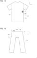
- FIGS. 1 and 2 show a garment C1 to which a connector assembly according to Embodiment 1 is attached.
- the garment C1 is a so-called top such as a shirt a user wears, and is made of a front body F1 and a back body F2 sewn to each other at sewing portions F3 in their lateral parts.
- FIG. 1 shows an outer surface of the front body F1
- FIG. 2 shows an outer surface of the back body F2.
- the front body F1 and the back body F2 are defined as extending along an XY plane
- the sewing portions F3 situated at opposite ends in the X direction are defined as extending along the Y direction
- a direction perpendicular to an XY plane is referred to as "Z direction.”
- a connector 11 is attached to the garment C1 to protrude to an outside of the front body F1 and the back body F2 from their sewing portions F3 on the -X direction side among the sewing portions F3 situated at the opposite ends in the X direction.
- FIG. 3 shows an inner surface of the front body F1.
- the inner surface of the front body F1 is a surface that faces a user's body when the user wears the garment C1. Part of cloth of the garment C1 protrudes in the -X direction from the -X directional edge of the front body F1, and a sheet-like base 21 that is flexible is formed of the cloth of the garment C1 constituting this protruding portion and the front body F1.
- the sheet-like base 21 includes a base body 21A formed of a part corresponding to the front body F1, and a tag portion 21B formed of a part corresponding to the protruding portion protruding in the -X direction from the -X directional edge of the front body F1.
- a plurality of electrodes 22 constituting a terminal member are attached, and a plurality of wires 23 are also provided, one ends of which are separately connected to the electrodes 22, and the other ends of which extend to the tag portion 21B.
- the connector 11 is mounted on a front surface of the tag portion 21B forming a same plane as that of the front surface of the base body 21A. At the tag portion 21B, the other ends of the wires 23 are connected to the connector 11.
- the connector assembly according to Embodiment 1 is composed of the sheet-like base 21, the electrodes 22 and the wires 23 attached to the front surface of the base body 21A, and the connector 11 mounted on the tag portion 21B shown in FIG. 3 .
- the other ends of the wires 23 disposed on the front surface of the base body 21A extend to the front surface of the tag portion 21B and are separately connected to connecting portions 24 disposed on the tag portion 21B.
- the electrodes 22 constituting the terminal member are used to acquire the user's biological data and disposed on the front surface of the base body 21A that faces the user's body when the garment C1 is worn, due to the necessity of being disposed in contact with or in the vicinity of the user's body surface.
- the wires 23 are disposed on the front surface of the base body 21A.
- Each electrode 22 can be made of a metal material and, besides, can be made by weaving or knitting a conductive thread. In addition, use may be made of an electrode 22 in which a conductive layer is formed through printing or another method on a front surface of an insulating resin film.
- FIG. 5 shows an assembly view of the connector 11.
- the connector 11 is used as, for example, a garment-side connector portion for fitting a wearable device, and includes a first insulator 13 and a second insulator 14 forming a housing 12, a plurality of contacts 15 held by the housing 12, and a reinforcement sheet 16 for reinforcing the tag portion 21B of the garment C1.
- the reinforcement sheet 16, the contacts 15, and the first insulator 13 are sequentially arranged, and on the rear surface side of the tag portion 21B, the second insulator 14 is arranged.
- the first insulator 13 includes a plurality of through holes 13A in which the +Z directional parts of the contacts 15 are inserted
- the second insulator 14 includes a plurality of projections 14A corresponding to the contacts 15 and projecting in the +Z direction
- the reinforcement sheet 16 is provided with an opening portion 16A at the center thereof.
- the contacts 15 are separately arranged over the connecting portions 24 disposed on the front surface of the tag portion 21B, the reinforcement sheet 16 is arranged on the front surface of the tag portion 21B such that the contacts 15 are situated inside the opening portion 16A of the reinforcement sheet 16, and the first insulator 13 is arranged on the reinforcement sheet 16.
- the +Z directional parts of the contacts 15 are separately inserted into the through-holes 13A of the first insulator 13 to project in the +Z direction from the first insulator 13.
- the second insulator 14 is moved from the -Z direction to the +Z direction and is pressed against the first insulator 13, whereby the projections 14A of the second insulator 14 make contact with the rear surface of the tag portion 21B facing in the -Z direction, and the cloth of the garment C1 constituting the tag portion 21B and the connecting portions 24 disposed on the front surface of the tag portion 21B are pushed toward the +Z direction.
- each projection 14A of the second insulator 14 is inserted into a recess portion 15A formed in the corresponding contact 15 with the tag portion 21B being sandwiched therebetween. Consequently, the connecting portion 24 disposed on the front surface of the tag portion 21B is jutted in the +Z direction toward the recess portion 15A and deformed by the projection 14A, an inner peripheral surface of the recess portion 15A of the contact 15 makes contact with the connecting portion 24, and the contact 15 is electrically connected to the connecting portion 24.
- the plurality of contacts 15 of the connector 11 are electrically connected to the plurality of electrodes 22 attached to the front surface of the base body 21A via the connecting portions 24 and the wires 23 in this manner.
- the connector 11 mounted on the tag portion 21B is not limited to the connector shown in FIGS. 5 and 6 , and connectors having various structures can be mounted on the tag portion 21B.
- the front body F1 including the base body 21A is sewn to the back body F2 by use of the sewing portions F3, and the tag portion 21B protrudes to the -X direction side from the sewing portion F3 as shown in FIG. 7 .
- the tag portion 21B on which the connector 11 is mounted is folded toward the base body 21A at the sewing portion F3 such that the rear surface of the tag portion 21B faces the rear surface of the base body 21A, and is sewn to the base body 21A using a sewing thread 25 as shown in FIG. 8 . Accordingly, the tag portion 21B is fixed to the base body 21A, and the connector 11 mounted on the tag portion 21B is disposed on the rear surface side, facing in the -Z direction, of the base body 21A, i.e., on an outer surface of the front body F1 as shown in FIG. 9 .
- the plurality of electrodes 22 and the plurality of wires 23 are disposed on the front surface of the base body 21A of the sheet-like base 21, the connector 11 is mounted on the tag portion 21B protruding from the base body 21A to an outside of the base body 21A, and the tag portion 21B is folded toward the base body 21A such that the rear surface of the tag portion 21B faces the rear surface of the base body 21A, whereby the connector 11 is disposed on the rear surface side of the base body 21A.
- the connector 11 when the user wears the garment C1, the connector 11 is situated on the outside of the garment C1 with respect to the user's body; it is thus possible to acquire biological data via the electrodes 22 without degrading comfortableness in wearing the garment C1.
- the folded tag portion 21B is sewn and fixed to the base body 21A, even the garment C1 provided with the tag portion 21B on which the connector 11 is mounted can be worn without uncomfortable feeling.
- the connector assembly is formed in the front body F1 of the garment C1, but this is not the sole case, and the connector assembly can be formed in the back body F2. That is, the base body may be formed of cloth of the garment C1 constituting the back body F2, and part of the cloth of the garment C1 constituting the back body F2 may protrude to an outside of the back body F2 to form the tag portion, on which the connector 11 is mounted.
- the plurality of electrodes 22 and the plurality of wires 23 are disposed on the front surface of the base body 21A, it suffices if at least one electrode 22 and at least one wire 23 are disposed.
- FIGS. 10 and 11 show a garment C2 to which a connector assembly according to Embodiment 2 is attached.
- the garment C2 is a top a user wears, and is made of the front body F1 and the back body F2 sewn to each other at sewing portions F3 in their lateral parts.
- FIG. 10 shows an outer surface of the front body F1
- FIG. 11 shows an outer surface of the back body F2.
- the connector 11 is attached to the garment C2 to protrude to an outside of the front body F1 and the back body F2 from their sewing portions F3 on the +X direction side among the sewing portions F3 situated at the opposite ends in the X direction.
- the outer surface of the front body F1 shown in FIG. 10 is a surface that faces outward in the opposite direction from a user's body when the user wears the garment C2.
- Part of cloth of the garment C2 protrudes in the +X direction from the +X directional edge of the front body F1, and the flexible sheet-like base 26 is formed of the cloth of the garment C2 constituting this protruding portion and the front body F1.
- the sheet-like base 26 includes a base body 26A formed of part corresponding to the front body F1, and a tag portion 26B formed of part corresponding to the protruding portion protruding in the +X direction from the +X directional edge of the front body F1.
- a plurality of sensors 27 constituting a terminal member are attached, and a plurality of wires 28 are also provided, one ends of which are separately connected to the sensors 27, and the other ends of which extend to the tag portion 26B.
- the connector 11 is mounted on a front surface of the tag portion 26B forming a same plane as that of the front surface of the base body 26A. At the tag portion 26B, the other ends of the wires 28 are connected to the connector 11.
- the connector assembly according to Embodiment 2 is composed of the sheet-like base 26, the sensors 27 and the wires 28 attached to the front surface of the base body 26A, and the connector 11 mounted on the tag portion 26B shown in FIG. 10 .
- the other ends of the wires 28 disposed on the front surface of the base body 26A extend to the front surface of the tag portion 26B and are separately connected to connecting portions 29 disposed on the tag portion 26B.
- angular rate sensors, acceleration sensors, and temperature sensors can be attached to the front surface of the base body 26A, and a module-side connector (not shown) on which a predetermined processor is mounted is fitted to the connector 11, whereby an inertial measurement unit for detecting three-dimensional inertial motion can be composed of the sensors 27 and the processor.
- the sensors 27 as above need not be in contact with or in the vicinity of the user's body surface, in consideration of comfortableness in wearing the garment C2, the sensors 27 are preferably disposed on the front surface of the base body 26A facing outward in the opposite direction from the user's body when the garment C2 is worn, and the wires 28 are also disposed on the front surface of the base body 26A in alignment with the sensors 27.
- the wires 28 are the same as the wires 23 used in Embodiment 1, and the connector 11 mounted on the tag portion 26B is also same as the connector 11 used in Embodiment 1.
- the front body F1 including the base body 26A is sewn to the back body F2 by use of the sewing portions F3, and the tag portion 26B protrudes to the +X direction side from the sewing portion F3 as shown in FIG. 13 .
- the tag portion 26B on which the connector 11 is mounted is folded to the back body F2 side toward the base body 26A such that the rear surface of the tag portion 26B faces the rear surface of the base body 26A, and is sewn to the back body F2 using the sewing thread 25 as shown in FIG. 14 .
- the connector 11 mounted on the tag potion 26B is disposed on the rear surface side of the base body 26A, i.e., on an outer surface of the back body F2 as shown in FIG. 15 .
- the plurality of sensors 27 and the plurality of wires 28 are disposed on the front surface of the base body 26A of the sheet-like base 26, the connector 11 is mounted on the tag portion 26B protruding from the base body 26A to an outside of the base body 26A, and the tag portion 26B is folded to the back body F2 side toward the base body 26A such that the rear surface of the tag portion 26B faces the rear surface of the base body 26A
- the connector 11 when the user wears the garment C2 the connector 11 is situated on the back side of the user and on an outside of the garment C2; it is thus possible to detect, for example, three-dimensional inertial motion using the sensors 27 without degrading comfortableness in wearing the garment C2.
- the connector assembly is formed in the front body F1 of the garment C2, but this is not the sole case, and the connector assembly can be formed in the back body F2.
- the plurality of sensors 27 and the plurality of wires 28 are disposed on the front surface of the base body 26A, it suffices if at least one sensor 27 and at least one wire 28 are disposed.
- FIG. 16 shows a garment C3 to which a connector assembly according to Embodiment 3 is attached.
- the garment C3 is a so-call bottom such as a pair of pants or a skirt a user wears, and includes a waist portion G1, and an opening portion G2 adjacent to the waist portion G1.
- Part of cloth of the garment C3 protrudes in the +Y direction from the opening portion G2 situated at the +Y directional end of the waist portion G1, and a flexible sheet-like base 31 is formed of cloth of the garment C3 constituting this protruding portion and the waist portion G1.
- the sheet-like base 31 includes a base body 31A formed of part corresponding to the waist portion G1 and a tag portion 31B formed of part corresponding to the protruding portion protruding in the +Y direction from the opening portion G2, and the connector 11 is mounted on the tag portion 31B.
- a plurality of electrodes constituting a terminal member and a plurality of wires connected to the electrodes are disposed on a front surface of the base body 31A of the waist portion G1 facing the user's body when the garment C3 is worn, i.e., on an inner surface of the waist portion G1, and one ends of the wires extend to the tag portion 31B and are connected to the connector 11 at the tag portion 31B.
- the connector assembly according to Embodiment 3 is composed of the sheet-like base 31, the electrodes and the wires disposed on the front surface of the base body 31A, and the connector 11 mounted on the tag portion 31B.
- the tag portion 31B on which the connector 11 is mounted is protruding in the +Y direction from the opening portion G2 of the garment C3 as shown in FIG. 16 .
- the tag portion 31B on which the connector 11 is mounted is folded to the base body 31A side at the +Y directional end of the opening portion G2, specifically, to the outer surface side of the waist portion G1, and is sewn to the base body 31A as with Embodiment 1.
- Embodiment 3 it is possible also in Embodiment 3 to acquire biological information via the electrodes without deteriorating comfortableness in wearing the garment C3, since the electrodes and the wires are disposed on the front surface of the base body 31A of the sheet-like base 31, the connector 11 is mounted on the tag portion 31B protruding in the +Y direction from the opening portion G2, and the tag portion 31B is folded toward the base body 31A such that the rear surface of the tag portion 31B faces the rear surface of the base body 31A, whereby the connector 11 is disposed on the rear surface side of the base body 31, i.e., on the outer surface side of the waist portion G1.
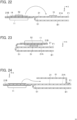
- FIGS. 18 and 19 show an electrical device E1 with pads which includes a connector assembly according to Embodiment 4.
- the electrical device E1 with pads is a device that is directly or indirectly mounted to a user's body with use of an adhesive pad.
- the electrical device E1 with pads includes a flexible sheet-like base 41 formed of, for example, an insulating resin film and extending along an XY plane.
- the sheet-like base 41 includes a base body 41A extending so as to form an H shape in an XY plane and a tag portion 41B protruding from a center part of the base body 41A toward an outside of the base body 41A in the +X direction.
- FIG. 18 shows a rear surface of the sheet-like base 41 as viewed from an outer side of the electrical device E1 with pads mounted on the user's body, i.e., the opposite side from the user's body
- FIG. 19 shows a front surface of the sheet-like base 41 as viewed from an inner side of the electrical device E1 with pads mounted on the user's body, i.e., the user's body side.
- a plurality of electrodes 42 separately arranged at a plurality of end portions of the base body 41A of H shape, and a plurality of wires 43 with one ends thereof being separately connected to the electrodes 42 and the other ends thereof extending to the tag portion 41B.
- the connector 11 is mounted on a front surface of the tag portion 41B forming a same plane as that of the front surface of the base body 41A. At the tag portion 41B, the other ends of the wires 43 are connected to the connector 11.
- the connector assembly according to Embodiment 4 is composed of the sheet-like base 41, the electrodes 42 and the wires 43 disposed on the front surface of the base body 41A, and the connector 11 mounted on the tag portion 41B.
- Each electrode 42 constitutes a terminal member and has a pad-like shape, forming an adhesive pad that sticks to, for example, the user's body surface.
- the electrode 42 may be configured such that its conductive surface of pad-like shape is adhesive, or a conductor constituting the electrode 42 may be embedded in an adhesive pad.
- each wire 43 use can be made of one formed through printing or another method as a conductive layer on a front surface of the sheet-like base 41 made of an insulating resin film.
- the other ends of the wires 43 disposed on the front surface of the base body 41A extend to the front surface of the tag portion 41B and are separately connected to connecting portions 44 disposed on the tag portion 41B.
- the connector 11 By mounting the connector 11 on the tag portion 41B, four contacts 15 of the connector 11 are separately and electrically connected to the corresponding connecting portion 44.
- the tag portion 41B on which the connector 11 is mounted is folded to the outer side of the electrical device E1 with pads toward the base body 41A such that the rear surface of the tag portion 41B faces the rear surface of the base body 41A as shown in FIG. 21 .
- the folded tag portion 41B is preferably sewn to or bonded to the base body 41A.
- Embodiment 4 it is possible also in Embodiment 4 to attach the electrical device E1 with pads to the user's body without uncomfortable feeling and to acquire biological information, since the electrodes 42 and the wires 43 are disposed on the front surface of the base body 41A of the sheet-like base 41, the connector 11 is mounted on the tag portion 41B protruding in the +X direction from the base body 41A, and the tag portion 41B is folded toward the base body 41A such that the rear surface of the tag portion 41B faces the rear surface of the base body 41A, whereby the connector 11 is disposed on the rear surface side of the base body 41A, i.e., on the outer side of the electrical device E1 with pads.
- the electrical device E1 with pads is applicable to not only a device that acquires biological information of a user via the electrodes 42 but also devices including, for example, a so-called low-frequency therapy device that gives an electrical stimulus to a nerve or a muscle by applying an electric current to a user's body via the electrode 42 from a module-side connector (not shown) fitted to the connector 11 and a so-called electric muscle stimulation (EMS) device that constrainedly causes muscle movement by applying an electric current to a user's body.
- EMS electric muscle stimulation
- the tag portion 21B on which the connector 11 is mounted and which is folded is sewn to and thus fixed to the base body 21A as shown in FIG. 8 , but the method of fixing the tag portion 21B to the base body 21A is not limited thereto.
- a first fixing member 51 is disposed on the rear surface side, facing in the -Z direction, of the base body 21A, and a second fixing member 52 is disposed on the rear surface, facing in the -Z direction, of the second insulator 14 of the connector 11 mounted on the tag portion 21B.
- the first fixing member 51 and the second fixing member 52 can be fixed to each other and can be each formed of, for example, a snap button, a hook-and-loop fastener, and a magnet.
- the second fixing member 52 of the tag portion 21B that is folded to the rear surface side of the base body 21A is fixed to the first fixing member 51 of the base body 21A, whereby the tag portion 21B on which the connector 11 is mounted can be fixed to the rear surface side of the base body 21A.
- a connector accommodation portion 61 of bag-like shape can be disposed on the rear surface side of the base body 21A.
- the connector accommodation portion 61 is opened on its -X direction side where the tag portion 21B is situated, and has a size allowing the tag portion 21B on which the connector 11 is mounted to be accommodated therein.
- the connector accommodation portion 61 as above can be formed of part of the cloth constituting the garment C1 or of a material different from the cloth of the garment C1.
- the tag portion 21B folded to the rear surface side of the base body 21A is accommodated in the connector accommodation portion 61, whereby the tag portion 21B on which the connector 11 is mounted can be fixed to the rear surface side of the base body 21A.
- the tag portion 21B on which the connector 11 is mounted can be fixed to the rear surface side of the base body 21A.
- the connector assembly according to the invention can be applied to not only the garment C1, C2, C3 and the electrical device E1 with pads but also a wide variety of wearing articles worn by a user.
- the connector assembly according to the invention by attaching the connector assembly according to the invention to a seat, a bed, a bedding piece, or the like in or on which a user lies, the connector 11 can be mounted without degrading comfortableness.
Landscapes
- Engineering & Computer Science (AREA)
- Textile Engineering (AREA)
- Professional, Industrial, Or Sporting Protective Garments (AREA)
- Measurement And Recording Of Electrical Phenomena And Electrical Characteristics Of The Living Body (AREA)
- Details Of Garments (AREA)
Claims (15)
- Verbinderanordnung, umfassend:eine flachmaterialartige Basis (21, 26, 31, 41), die flexibel ist, wobei die flachmaterialartige Basis einen Basiskörper (21A, 26A, 31A, 41A) und einen von dem Basiskörper gezogenen Laschenabschnitt (21B, 26B, 31B, 41B) aufweist;mindestens ein Anschlusselement (22, 27, 42), das auf einer vorderen Fläche des Basiskörpers angeordnet ist;mindestens einen Draht (23, 28, 43), der so angeordnet ist, dass er sich von der vorderen Fläche des Basiskörpers zu einer vorderen Fläche des Laschenabschnitts erstreckt, wobei ein Ende des mindestens einen Drahtes mit dem mindestens einen Anschlusselement verbunden ist und sein anderes Ende sich zu der vorderen Fläche des Laschenabschnitts erstreckt; undeinen Verbinder (11), der an der vorderen Fläche des Laschenabschnitts montiert ist und mit dem anderen Ende des mindestens einen Drahtes verbunden ist,wobei der Laschenabschnitt so in Richtung des Basiskörpers gefaltet und an dem Basiskörper befestigt ist, dass eine hintere Fläche des Laschenabschnitts einer hinteren Fläche des Basiskörpers zugewandt ist, wodurch der Verbinder an der Seite der hinteren Fläche des Basiskörpers angeordnet ist.
- Verbinderanordnung nach Anspruch 1, wobei der gefaltete Laschenabschnitt (21B, 26B, 31B, 41B) an den Basiskörper (21A, 26A, 31A, 41A) genäht und dadurch an dem Basiskörper befestigt ist.
- Verbinderanordnung nach Anspruch 1, umfassend des Weiteren:ein erstes Befestigungselement (51), das an der Seite der hinteren Fläche des Basiskörpers angeordnet ist; undein zweites Befestigungselement (52), das an der Seite der hinteren Fläche des Laschenabschnitts angeordnet und an dem ersten Befestigungselement befestigt ist,wobei das erste Befestigungselement und das zweite Befestigungselement aneinander befestigt sind, wodurch der gefaltete Laschenabschnitt an dem Basiskörper befestigt ist.
- Verbinderanordnung nach Anspruch 1, umfassend des Weiteren einen Verbinderaufnahmeabschnitt (61), der an der Seite der hinteren Fläche des Basiskörpers angeordnet ist,
wobei der gefaltete Laschenabschnitt zusammen mit dem Verbinder in dem Verbinderaufnahmeabschnitt aufgenommen und dadurch an dem Basiskörper befestigt ist. - Verbinderanordnung nach einem der Ansprüche 1-4, wobei die flachmaterialartige Basis aus dem Stoff eines Kleidungsstücks (C1, C2, C3) gebildet ist.
- Verbinderanordnung nach Anspruch 5,wobei das Kleidungsstück (C1, C2) einen vorderen Körper (F1) und einen hinteren Körper (F2) aufweist, die aneinander genäht sind,der Basiskörper (21A, 26A) aus dem Stoff gebildet ist, der einen des vorderen Körpers und des hinteren Körpers bildet, undder Laschenabschnitt (21B, 26B) von einem Nähabschnitt des vorderen Körpers oder des hinteren Körpers zu einer Außenseite des Kleidungsstücks gezogen ist.
- Verbinderanordnung nach Anspruch 6,wobei die vordere Fläche des Basiskörpers (21A) aus einer einer Innenseite des Kleidungsstücks (C1) zugewandten Fläche des einen des vorderen Körpers und des hinteren Körpers gebildet ist unddas Anschlusselement aus einer Elektrode (22) zusammengesetzt ist.
- Verbinderanordnung nach Anspruch 6,wobei die vordere Fläche des Basiskörpers (26A) aus einer einer Außenseite des Kleidungsstücks (C2) zugewandten Fläche des einen des vorderen Körpers und des hinteren Körpers gebildet ist unddas Anschlusselement aus einem Sensor (27) zusammengesetzt ist.
- Verbinderanordnung nach Anspruch 8, wobei der gefaltete Laschenabschnitt (26B) an einem anderen des vorderen Körpers und des hinteren Körpers befestigt ist.
- Verbinderanordnung nach Anspruch 5,wobei das Kleidungsstück (C3) einen Taillenabschnitt (G1) neben einem Öffnungsabschnitt (G2) aufweist,der Basiskörper (31A) aus dem Stoff gebildet ist, der den Taillenabschnitt bildet,die vordere Fläche des Basiskörpers aus einer Fläche des Taillenabschnitts gebildet ist, die seiner Innenseite zugewandt ist, undder Laschenabschnitt (31B) von dem Öffnungsabschnitt zu einer Außenseite des Kleidungsstücks gezogen ist.
- Verbinderanordnung nach einem der Ansprüche 1-4, wobei die flachmaterialartige Basis (41) aus einem isolierenden Harzfilm gebildet ist.
- Kleidungsstück (C1, C2, C3), umfassend die Verbindungsanordnung nach einem der Ansprüche 1-11,
wobei die flachmaterialartige Basis mindestens teilweise aus Stoff des Kleidungsstücks gebildet ist. - Kleidungsstück (C1, C2) nach Anspruch 12, umfassend des Weiteren einen vorderen Körper (F1) und einen hinteren Körper (F2), die aneinander genäht sind,wobei der Basiskörper (21A, 26A) aus dem Stoff gebildet ist, der einen des vorderen Körpers und des hinteren Körpers bildet, undder Laschenabschnitt (21B, 26B) von einem Nähabschnitt des vorderen Körpers oder des hinteren Körpers gezogen ist.
- Kleidungsstück (C3) nach Anspruch 12, umfassend des Weiteren einen Taillenabschnitt (G1) neben einem Öffnungsabschnitt (G2),wobei der Basiskörper (31A) aus dem Stoff gebildet ist, der den Taillenabschnitt bildet, undder Laschenabschnitt (31B) von dem Öffnungsabschnitt gezogen ist.
- Elektrische Vorrichtung (E1) mit einem Pad, umfassend die Verbinderanordnung nach Anspruch 11,
wobei das mindestens eine Anschlusselement aus einer Elektrode (42) zusammengesetzt ist, die eine padartige Form hat.
Applications Claiming Priority (1)
| Application Number | Priority Date | Filing Date | Title |
|---|---|---|---|
| JP2023068438A JP2024154559A (ja) | 2023-04-19 | 2023-04-19 | コネクタ組立体、衣服およびパッド付き電気機器 |
Publications (2)
| Publication Number | Publication Date |
|---|---|
| EP4451477A1 EP4451477A1 (de) | 2024-10-23 |
| EP4451477B1 true EP4451477B1 (de) | 2025-05-07 |
Family
ID=90105141
Family Applications (1)
| Application Number | Title | Priority Date | Filing Date |
|---|---|---|---|
| EP24160354.7A Active EP4451477B1 (de) | 2023-04-19 | 2024-02-28 | Verbinderanordnung, kleidungsstück und elektrische vorrichtung mit pad |
Country Status (4)
| Country | Link |
|---|---|
| US (1) | US20240356258A1 (de) |
| EP (1) | EP4451477B1 (de) |
| JP (1) | JP2024154559A (de) |
| CN (1) | CN118825662A (de) |
Family Cites Families (4)
| Publication number | Priority date | Publication date | Assignee | Title |
|---|---|---|---|---|
| US6687523B1 (en) * | 1997-09-22 | 2004-02-03 | Georgia Tech Research Corp. | Fabric or garment with integrated flexible information infrastructure for monitoring vital signs of infants |
| EP3267814A1 (de) * | 2015-03-12 | 2018-01-17 | Flaviatex S.r.l. | Kleidungsstück, insbesondere zur elektrostimulation, und verfahren zur herstellung des kleidungsstücks |
| WO2019009276A1 (ja) * | 2017-07-03 | 2019-01-10 | 東洋紡株式会社 | 生体情報計測用衣類 |
| JP7438085B2 (ja) | 2020-11-18 | 2024-02-26 | 日本航空電子工業株式会社 | コネクタ |
-
2023
- 2023-04-19 JP JP2023068438A patent/JP2024154559A/ja active Pending
-
2024
- 2024-02-21 CN CN202410196508.7A patent/CN118825662A/zh active Pending
- 2024-02-21 US US18/583,060 patent/US20240356258A1/en active Pending
- 2024-02-28 EP EP24160354.7A patent/EP4451477B1/de active Active
Also Published As
| Publication number | Publication date |
|---|---|
| US20240356258A1 (en) | 2024-10-24 |
| JP2024154559A (ja) | 2024-10-31 |
| EP4451477A1 (de) | 2024-10-23 |
| CN118825662A (zh) | 2024-10-22 |
Similar Documents
| Publication | Publication Date | Title |
|---|---|---|
| US10617156B2 (en) | Electronic housing and sensor connection arrangement | |
| US9247907B2 (en) | Garment with receptacle and electronic module | |
| CN104869898B (zh) | 电极组件 | |
| EP2671290B1 (de) | Textilsubstrat zur messung einer physikalischen grösse | |
| JP6457355B2 (ja) | ウェアラブル電極および生体信号モニタシステム | |
| KR20040018306A (ko) | 바이탈 사인을 모니터링하는 신규한 직물기재 센서 | |
| CN214706283U (zh) | 用于形成穿戴装置的结合构造 | |
| WO2018121708A1 (en) | Wearable motion capture apparatus and virtual reality system | |
| KR101897216B1 (ko) | 생체신호 측정장치가 구비된 의류 | |
| EP4451477B1 (de) | Verbinderanordnung, kleidungsstück und elektrische vorrichtung mit pad | |
| EP4395474B1 (de) | Verbinder und verbinderanordnung | |
| US10310558B2 (en) | Apparatus and method for computing node and seat connection for conductive fabric | |
| KR102786578B1 (ko) | 옷 기능을 갖는 웨어러블 장치 | |
| WO2019155238A1 (en) | Textile electronic contact | |
| JP7681225B2 (ja) | 導電性布用コネクタ | |
| KR101961728B1 (ko) | 생체신호 측정기능을 갖는 스마트 의류 및 그 제조방법 | |
| US20220053637A1 (en) | Textile device configured to cooperate with an electronic device | |
| WO2019155237A1 (en) | Textile connector | |
| KR20240033664A (ko) | 부착 위치를 감지할 수 있는 웨어러블 장치 | |
| JP7385093B2 (ja) | 導電性布用コネクタ | |
| CN216875083U (zh) | 一种运动衣 | |
| JP2024102527A (ja) | コネクタ | |
| JP2018050650A (ja) | ウエアラブル機器用接続部品およびウエアラブル機器 | |
| TW201915243A (zh) | 織物結構 |
Legal Events
| Date | Code | Title | Description |
|---|---|---|---|
| PUAI | Public reference made under article 153(3) epc to a published international application that has entered the european phase |
Free format text: ORIGINAL CODE: 0009012 |
|
| STAA | Information on the status of an ep patent application or granted ep patent |
Free format text: STATUS: REQUEST FOR EXAMINATION WAS MADE |
|
| 17P | Request for examination filed |
Effective date: 20240228 |
|
| AK | Designated contracting states |
Kind code of ref document: A1 Designated state(s): AL AT BE BG CH CY CZ DE DK EE ES FI FR GB GR HR HU IE IS IT LI LT LU LV MC ME MK MT NL NO PL PT RO RS SE SI SK SM TR |
|
| RAP3 | Party data changed (applicant data changed or rights of an application transferred) |
Owner name: JAPAN AVIATION ELECTRONICS INDUSTRY, LIMITED |
|
| RBV | Designated contracting states (corrected) |
Designated state(s): AL AT BE BG CH CY CZ DE DK EE ES FI FR GB GR HR HU IE IS IT LI LT LU LV MC ME MK MT NL NO PL PT RO RS SE SI SK SM TR |
|
| GRAP | Despatch of communication of intention to grant a patent |
Free format text: ORIGINAL CODE: EPIDOSNIGR1 |
|
| STAA | Information on the status of an ep patent application or granted ep patent |
Free format text: STATUS: GRANT OF PATENT IS INTENDED |
|
| RIC1 | Information provided on ipc code assigned before grant |
Ipc: H01R 12/77 20110101ALN20250210BHEP Ipc: H01R 12/59 20110101AFI20250210BHEP |
|
| INTG | Intention to grant announced |
Effective date: 20250219 |
|
| GRAS | Grant fee paid |
Free format text: ORIGINAL CODE: EPIDOSNIGR3 |
|
| GRAA | (expected) grant |
Free format text: ORIGINAL CODE: 0009210 |
|
| STAA | Information on the status of an ep patent application or granted ep patent |
Free format text: STATUS: THE PATENT HAS BEEN GRANTED |
|
| AK | Designated contracting states |
Kind code of ref document: B1 Designated state(s): AL AT BE BG CH CY CZ DE DK EE ES FI FR GB GR HR HU IE IS IT LI LT LU LV MC ME MK MT NL NO PL PT RO RS SE SI SK SM TR |
|
| REG | Reference to a national code |
Ref country code: GB Ref legal event code: FG4D |
|
| REG | Reference to a national code |
Ref country code: CH Ref legal event code: EP |
|
| REG | Reference to a national code |
Ref country code: DE Ref legal event code: R096 Ref document number: 602024000104 Country of ref document: DE |
|
| REG | Reference to a national code |
Ref country code: IE Ref legal event code: FG4D |
|
| REG | Reference to a national code |
Ref country code: NL Ref legal event code: MP Effective date: 20250507 |
|
| PG25 | Lapsed in a contracting state [announced via postgrant information from national office to epo] |
Ref country code: PT Free format text: LAPSE BECAUSE OF FAILURE TO SUBMIT A TRANSLATION OF THE DESCRIPTION OR TO PAY THE FEE WITHIN THE PRESCRIBED TIME-LIMIT Effective date: 20250908 Ref country code: FI Free format text: LAPSE BECAUSE OF FAILURE TO SUBMIT A TRANSLATION OF THE DESCRIPTION OR TO PAY THE FEE WITHIN THE PRESCRIBED TIME-LIMIT Effective date: 20250507 Ref country code: ES Free format text: LAPSE BECAUSE OF FAILURE TO SUBMIT A TRANSLATION OF THE DESCRIPTION OR TO PAY THE FEE WITHIN THE PRESCRIBED TIME-LIMIT Effective date: 20250507 |
|
| REG | Reference to a national code |
Ref country code: LT Ref legal event code: MG9D |
|
| PG25 | Lapsed in a contracting state [announced via postgrant information from national office to epo] |
Ref country code: GR Free format text: LAPSE BECAUSE OF FAILURE TO SUBMIT A TRANSLATION OF THE DESCRIPTION OR TO PAY THE FEE WITHIN THE PRESCRIBED TIME-LIMIT Effective date: 20250808 Ref country code: NO Free format text: LAPSE BECAUSE OF FAILURE TO SUBMIT A TRANSLATION OF THE DESCRIPTION OR TO PAY THE FEE WITHIN THE PRESCRIBED TIME-LIMIT Effective date: 20250807 |
|
| PG25 | Lapsed in a contracting state [announced via postgrant information from national office to epo] |
Ref country code: PL Free format text: LAPSE BECAUSE OF FAILURE TO SUBMIT A TRANSLATION OF THE DESCRIPTION OR TO PAY THE FEE WITHIN THE PRESCRIBED TIME-LIMIT Effective date: 20250507 Ref country code: NL Free format text: LAPSE BECAUSE OF FAILURE TO SUBMIT A TRANSLATION OF THE DESCRIPTION OR TO PAY THE FEE WITHIN THE PRESCRIBED TIME-LIMIT Effective date: 20250507 |
|
| REG | Reference to a national code |
Ref country code: AT Ref legal event code: MK05 Ref document number: 1793562 Country of ref document: AT Kind code of ref document: T Effective date: 20250507 |
|
| PG25 | Lapsed in a contracting state [announced via postgrant information from national office to epo] |
Ref country code: BG Free format text: LAPSE BECAUSE OF FAILURE TO SUBMIT A TRANSLATION OF THE DESCRIPTION OR TO PAY THE FEE WITHIN THE PRESCRIBED TIME-LIMIT Effective date: 20250507 |
|
| PG25 | Lapsed in a contracting state [announced via postgrant information from national office to epo] |
Ref country code: HR Free format text: LAPSE BECAUSE OF FAILURE TO SUBMIT A TRANSLATION OF THE DESCRIPTION OR TO PAY THE FEE WITHIN THE PRESCRIBED TIME-LIMIT Effective date: 20250507 |
|
| PG25 | Lapsed in a contracting state [announced via postgrant information from national office to epo] |
Ref country code: AT Free format text: LAPSE BECAUSE OF FAILURE TO SUBMIT A TRANSLATION OF THE DESCRIPTION OR TO PAY THE FEE WITHIN THE PRESCRIBED TIME-LIMIT Effective date: 20250507 |
|
| PG25 | Lapsed in a contracting state [announced via postgrant information from national office to epo] |
Ref country code: RS Free format text: LAPSE BECAUSE OF FAILURE TO SUBMIT A TRANSLATION OF THE DESCRIPTION OR TO PAY THE FEE WITHIN THE PRESCRIBED TIME-LIMIT Effective date: 20250807 |
|
| PG25 | Lapsed in a contracting state [announced via postgrant information from national office to epo] |
Ref country code: IS Free format text: LAPSE BECAUSE OF FAILURE TO SUBMIT A TRANSLATION OF THE DESCRIPTION OR TO PAY THE FEE WITHIN THE PRESCRIBED TIME-LIMIT Effective date: 20250907 |
|
| PG25 | Lapsed in a contracting state [announced via postgrant information from national office to epo] |
Ref country code: LV Free format text: LAPSE BECAUSE OF FAILURE TO SUBMIT A TRANSLATION OF THE DESCRIPTION OR TO PAY THE FEE WITHIN THE PRESCRIBED TIME-LIMIT Effective date: 20250507 |
|
| PG25 | Lapsed in a contracting state [announced via postgrant information from national office to epo] |
Ref country code: SM Free format text: LAPSE BECAUSE OF FAILURE TO SUBMIT A TRANSLATION OF THE DESCRIPTION OR TO PAY THE FEE WITHIN THE PRESCRIBED TIME-LIMIT Effective date: 20250507 Ref country code: DK Free format text: LAPSE BECAUSE OF FAILURE TO SUBMIT A TRANSLATION OF THE DESCRIPTION OR TO PAY THE FEE WITHIN THE PRESCRIBED TIME-LIMIT Effective date: 20250507 |
|
| PGFP | Annual fee paid to national office [announced via postgrant information from national office to epo] |
Ref country code: FR Payment date: 20251231 Year of fee payment: 3 |
|
| PG25 | Lapsed in a contracting state [announced via postgrant information from national office to epo] |
Ref country code: CZ Free format text: LAPSE BECAUSE OF FAILURE TO SUBMIT A TRANSLATION OF THE DESCRIPTION OR TO PAY THE FEE WITHIN THE PRESCRIBED TIME-LIMIT Effective date: 20250507 |
|
| PG25 | Lapsed in a contracting state [announced via postgrant information from national office to epo] |
Ref country code: EE Free format text: LAPSE BECAUSE OF FAILURE TO SUBMIT A TRANSLATION OF THE DESCRIPTION OR TO PAY THE FEE WITHIN THE PRESCRIBED TIME-LIMIT Effective date: 20250507 |
|
| PG25 | Lapsed in a contracting state [announced via postgrant information from national office to epo] |
Ref country code: SK Free format text: LAPSE BECAUSE OF FAILURE TO SUBMIT A TRANSLATION OF THE DESCRIPTION OR TO PAY THE FEE WITHIN THE PRESCRIBED TIME-LIMIT Effective date: 20250507 |
|
| PG25 | Lapsed in a contracting state [announced via postgrant information from national office to epo] |
Ref country code: IT Free format text: LAPSE BECAUSE OF FAILURE TO SUBMIT A TRANSLATION OF THE DESCRIPTION OR TO PAY THE FEE WITHIN THE PRESCRIBED TIME-LIMIT Effective date: 20250507 |