EP4451426A1 - Assembled battery - Google Patents
Assembled battery Download PDFInfo
- Publication number
- EP4451426A1 EP4451426A1 EP24165945.7A EP24165945A EP4451426A1 EP 4451426 A1 EP4451426 A1 EP 4451426A1 EP 24165945 A EP24165945 A EP 24165945A EP 4451426 A1 EP4451426 A1 EP 4451426A1
- Authority
- EP
- European Patent Office
- Prior art keywords
- battery cells
- conductive pattern
- inter
- battery
- electrode terminal
- Prior art date
- Legal status (The legal status is an assumption and is not a legal conclusion. Google has not performed a legal analysis and makes no representation as to the accuracy of the status listed.)
- Pending
Links
- 239000000758 substrate Substances 0.000 claims description 25
- 239000011347 resin Substances 0.000 claims description 11
- 229920005989 resin Polymers 0.000 claims description 11
- 238000001816 cooling Methods 0.000 claims description 6
- 229910052751 metal Inorganic materials 0.000 claims description 4
- 239000002184 metal Substances 0.000 claims description 4
- 238000010586 diagram Methods 0.000 description 11
- 229910052782 aluminium Inorganic materials 0.000 description 3
- XAGFODPZIPBFFR-UHFFFAOYSA-N aluminium Chemical compound [Al] XAGFODPZIPBFFR-UHFFFAOYSA-N 0.000 description 3
- -1 for example Substances 0.000 description 3
- 238000003466 welding Methods 0.000 description 3
- RYGMFSIKBFXOCR-UHFFFAOYSA-N Copper Chemical compound [Cu] RYGMFSIKBFXOCR-UHFFFAOYSA-N 0.000 description 2
- XEEYBQQBJWHFJM-UHFFFAOYSA-N Iron Chemical compound [Fe] XEEYBQQBJWHFJM-UHFFFAOYSA-N 0.000 description 2
- PXHVJJICTQNCMI-UHFFFAOYSA-N Nickel Chemical compound [Ni] PXHVJJICTQNCMI-UHFFFAOYSA-N 0.000 description 2
- BQCADISMDOOEFD-UHFFFAOYSA-N Silver Chemical compound [Ag] BQCADISMDOOEFD-UHFFFAOYSA-N 0.000 description 2
- 229910045601 alloy Inorganic materials 0.000 description 2
- 239000000956 alloy Substances 0.000 description 2
- 229910052802 copper Inorganic materials 0.000 description 2
- 239000010949 copper Substances 0.000 description 2
- PCHJSUWPFVWCPO-UHFFFAOYSA-N gold Chemical compound [Au] PCHJSUWPFVWCPO-UHFFFAOYSA-N 0.000 description 2
- 229910052737 gold Inorganic materials 0.000 description 2
- 239000010931 gold Substances 0.000 description 2
- 238000000034 method Methods 0.000 description 2
- 229910052709 silver Inorganic materials 0.000 description 2
- 239000004332 silver Substances 0.000 description 2
- 229910001369 Brass Inorganic materials 0.000 description 1
- RWSOTUBLDIXVET-UHFFFAOYSA-N Dihydrogen sulfide Chemical compound S RWSOTUBLDIXVET-UHFFFAOYSA-N 0.000 description 1
- HBBGRARXTFLTSG-UHFFFAOYSA-N Lithium ion Chemical compound [Li+] HBBGRARXTFLTSG-UHFFFAOYSA-N 0.000 description 1
- 239000004677 Nylon Substances 0.000 description 1
- 229920001283 Polyalkylene terephthalate Polymers 0.000 description 1
- 239000004642 Polyimide Substances 0.000 description 1
- 239000004743 Polypropylene Substances 0.000 description 1
- UCKMPCXJQFINFW-UHFFFAOYSA-N Sulphide Chemical compound [S-2] UCKMPCXJQFINFW-UHFFFAOYSA-N 0.000 description 1
- HCHKCACWOHOZIP-UHFFFAOYSA-N Zinc Chemical compound [Zn] HCHKCACWOHOZIP-UHFFFAOYSA-N 0.000 description 1
- 239000000853 adhesive Substances 0.000 description 1
- 230000001070 adhesive effect Effects 0.000 description 1
- 239000010951 brass Substances 0.000 description 1
- 238000007796 conventional method Methods 0.000 description 1
- 230000000694 effects Effects 0.000 description 1
- 239000003822 epoxy resin Substances 0.000 description 1
- 229910000037 hydrogen sulfide Inorganic materials 0.000 description 1
- 229910052742 iron Inorganic materials 0.000 description 1
- 229910001416 lithium ion Inorganic materials 0.000 description 1
- 229910052987 metal hydride Inorganic materials 0.000 description 1
- 239000007769 metal material Substances 0.000 description 1
- 229910052759 nickel Inorganic materials 0.000 description 1
- 229920001778 nylon Polymers 0.000 description 1
- 229920003229 poly(methyl methacrylate) Polymers 0.000 description 1
- 229920000515 polycarbonate Polymers 0.000 description 1
- 239000004417 polycarbonate Substances 0.000 description 1
- 229920000647 polyepoxide Polymers 0.000 description 1
- 229920000139 polyethylene terephthalate Polymers 0.000 description 1
- 239000005020 polyethylene terephthalate Substances 0.000 description 1
- 229920001721 polyimide Polymers 0.000 description 1
- 239000004926 polymethyl methacrylate Substances 0.000 description 1
- 229920001155 polypropylene Polymers 0.000 description 1
- 230000002265 prevention Effects 0.000 description 1
- 229920006300 shrink film Polymers 0.000 description 1
- 239000010935 stainless steel Substances 0.000 description 1
- 229910001220 stainless steel Inorganic materials 0.000 description 1
- 229910052725 zinc Inorganic materials 0.000 description 1
- 239000011701 zinc Substances 0.000 description 1
Images




Classifications
-
- H—ELECTRICITY
- H01—ELECTRIC ELEMENTS
- H01M—PROCESSES OR MEANS, e.g. BATTERIES, FOR THE DIRECT CONVERSION OF CHEMICAL ENERGY INTO ELECTRICAL ENERGY
- H01M50/00—Constructional details or processes of manufacture of the non-active parts of electrochemical cells other than fuel cells, e.g. hybrid cells
- H01M50/50—Current conducting connections for cells or batteries
- H01M50/502—Interconnectors for connecting terminals of adjacent batteries; Interconnectors for connecting cells outside a battery casing
- H01M50/509—Interconnectors for connecting terminals of adjacent batteries; Interconnectors for connecting cells outside a battery casing characterised by the type of connection, e.g. mixed connections
-
- H—ELECTRICITY
- H01—ELECTRIC ELEMENTS
- H01M—PROCESSES OR MEANS, e.g. BATTERIES, FOR THE DIRECT CONVERSION OF CHEMICAL ENERGY INTO ELECTRICAL ENERGY
- H01M50/00—Constructional details or processes of manufacture of the non-active parts of electrochemical cells other than fuel cells, e.g. hybrid cells
- H01M50/20—Mountings; Secondary casings or frames; Racks, modules or packs; Suspension devices; Shock absorbers; Transport or carrying devices; Holders
- H01M50/204—Racks, modules or packs for multiple batteries or multiple cells
-
- H—ELECTRICITY
- H01—ELECTRIC ELEMENTS
- H01M—PROCESSES OR MEANS, e.g. BATTERIES, FOR THE DIRECT CONVERSION OF CHEMICAL ENERGY INTO ELECTRICAL ENERGY
- H01M10/00—Secondary cells; Manufacture thereof
- H01M10/60—Heating or cooling; Temperature control
- H01M10/61—Types of temperature control
- H01M10/613—Cooling or keeping cold
-
- H—ELECTRICITY
- H01—ELECTRIC ELEMENTS
- H01M—PROCESSES OR MEANS, e.g. BATTERIES, FOR THE DIRECT CONVERSION OF CHEMICAL ENERGY INTO ELECTRICAL ENERGY
- H01M10/00—Secondary cells; Manufacture thereof
- H01M10/60—Heating or cooling; Temperature control
- H01M10/65—Means for temperature control structurally associated with the cells
- H01M10/655—Solid structures for heat exchange or heat conduction
- H01M10/6551—Surfaces specially adapted for heat dissipation or radiation, e.g. fins or coatings
-
- H—ELECTRICITY
- H01—ELECTRIC ELEMENTS
- H01M—PROCESSES OR MEANS, e.g. BATTERIES, FOR THE DIRECT CONVERSION OF CHEMICAL ENERGY INTO ELECTRICAL ENERGY
- H01M10/00—Secondary cells; Manufacture thereof
- H01M10/60—Heating or cooling; Temperature control
- H01M10/65—Means for temperature control structurally associated with the cells
- H01M10/655—Solid structures for heat exchange or heat conduction
- H01M10/6554—Rods or plates
-
- H—ELECTRICITY
- H01—ELECTRIC ELEMENTS
- H01M—PROCESSES OR MEANS, e.g. BATTERIES, FOR THE DIRECT CONVERSION OF CHEMICAL ENERGY INTO ELECTRICAL ENERGY
- H01M50/00—Constructional details or processes of manufacture of the non-active parts of electrochemical cells other than fuel cells, e.g. hybrid cells
- H01M50/10—Primary casings; Jackets or wrappings
- H01M50/102—Primary casings; Jackets or wrappings characterised by their shape or physical structure
- H01M50/112—Monobloc comprising multiple compartments
-
- H—ELECTRICITY
- H01—ELECTRIC ELEMENTS
- H01M—PROCESSES OR MEANS, e.g. BATTERIES, FOR THE DIRECT CONVERSION OF CHEMICAL ENERGY INTO ELECTRICAL ENERGY
- H01M50/00—Constructional details or processes of manufacture of the non-active parts of electrochemical cells other than fuel cells, e.g. hybrid cells
- H01M50/10—Primary casings; Jackets or wrappings
- H01M50/172—Arrangements of electric connectors penetrating the casing
-
- H—ELECTRICITY
- H01—ELECTRIC ELEMENTS
- H01M—PROCESSES OR MEANS, e.g. BATTERIES, FOR THE DIRECT CONVERSION OF CHEMICAL ENERGY INTO ELECTRICAL ENERGY
- H01M50/00—Constructional details or processes of manufacture of the non-active parts of electrochemical cells other than fuel cells, e.g. hybrid cells
- H01M50/20—Mountings; Secondary casings or frames; Racks, modules or packs; Suspension devices; Shock absorbers; Transport or carrying devices; Holders
- H01M50/244—Secondary casings; Racks; Suspension devices; Carrying devices; Holders characterised by their mounting method
-
- H—ELECTRICITY
- H01—ELECTRIC ELEMENTS
- H01M—PROCESSES OR MEANS, e.g. BATTERIES, FOR THE DIRECT CONVERSION OF CHEMICAL ENERGY INTO ELECTRICAL ENERGY
- H01M50/00—Constructional details or processes of manufacture of the non-active parts of electrochemical cells other than fuel cells, e.g. hybrid cells
- H01M50/20—Mountings; Secondary casings or frames; Racks, modules or packs; Suspension devices; Shock absorbers; Transport or carrying devices; Holders
- H01M50/289—Mountings; Secondary casings or frames; Racks, modules or packs; Suspension devices; Shock absorbers; Transport or carrying devices; Holders characterised by spacing elements or positioning means within frames, racks or packs
- H01M50/291—Mountings; Secondary casings or frames; Racks, modules or packs; Suspension devices; Shock absorbers; Transport or carrying devices; Holders characterised by spacing elements or positioning means within frames, racks or packs characterised by their shape
-
- H—ELECTRICITY
- H01—ELECTRIC ELEMENTS
- H01M—PROCESSES OR MEANS, e.g. BATTERIES, FOR THE DIRECT CONVERSION OF CHEMICAL ENERGY INTO ELECTRICAL ENERGY
- H01M50/00—Constructional details or processes of manufacture of the non-active parts of electrochemical cells other than fuel cells, e.g. hybrid cells
- H01M50/50—Current conducting connections for cells or batteries
- H01M50/502—Interconnectors for connecting terminals of adjacent batteries; Interconnectors for connecting cells outside a battery casing
- H01M50/503—Interconnectors for connecting terminals of adjacent batteries; Interconnectors for connecting cells outside a battery casing characterised by the shape of the interconnectors
-
- H—ELECTRICITY
- H01—ELECTRIC ELEMENTS
- H01M—PROCESSES OR MEANS, e.g. BATTERIES, FOR THE DIRECT CONVERSION OF CHEMICAL ENERGY INTO ELECTRICAL ENERGY
- H01M50/00—Constructional details or processes of manufacture of the non-active parts of electrochemical cells other than fuel cells, e.g. hybrid cells
- H01M50/50—Current conducting connections for cells or batteries
- H01M50/502—Interconnectors for connecting terminals of adjacent batteries; Interconnectors for connecting cells outside a battery casing
- H01M50/509—Interconnectors for connecting terminals of adjacent batteries; Interconnectors for connecting cells outside a battery casing characterised by the type of connection, e.g. mixed connections
- H01M50/51—Connection only in series
-
- H—ELECTRICITY
- H01—ELECTRIC ELEMENTS
- H01M—PROCESSES OR MEANS, e.g. BATTERIES, FOR THE DIRECT CONVERSION OF CHEMICAL ENERGY INTO ELECTRICAL ENERGY
- H01M50/00—Constructional details or processes of manufacture of the non-active parts of electrochemical cells other than fuel cells, e.g. hybrid cells
- H01M50/50—Current conducting connections for cells or batteries
- H01M50/502—Interconnectors for connecting terminals of adjacent batteries; Interconnectors for connecting cells outside a battery casing
- H01M50/509—Interconnectors for connecting terminals of adjacent batteries; Interconnectors for connecting cells outside a battery casing characterised by the type of connection, e.g. mixed connections
- H01M50/512—Connection only in parallel
-
- H—ELECTRICITY
- H01—ELECTRIC ELEMENTS
- H01M—PROCESSES OR MEANS, e.g. BATTERIES, FOR THE DIRECT CONVERSION OF CHEMICAL ENERGY INTO ELECTRICAL ENERGY
- H01M50/00—Constructional details or processes of manufacture of the non-active parts of electrochemical cells other than fuel cells, e.g. hybrid cells
- H01M50/50—Current conducting connections for cells or batteries
- H01M50/502—Interconnectors for connecting terminals of adjacent batteries; Interconnectors for connecting cells outside a battery casing
- H01M50/521—Interconnectors for connecting terminals of adjacent batteries; Interconnectors for connecting cells outside a battery casing characterised by the material
-
- H—ELECTRICITY
- H01—ELECTRIC ELEMENTS
- H01M—PROCESSES OR MEANS, e.g. BATTERIES, FOR THE DIRECT CONVERSION OF CHEMICAL ENERGY INTO ELECTRICAL ENERGY
- H01M50/00—Constructional details or processes of manufacture of the non-active parts of electrochemical cells other than fuel cells, e.g. hybrid cells
- H01M50/50—Current conducting connections for cells or batteries
- H01M50/502—Interconnectors for connecting terminals of adjacent batteries; Interconnectors for connecting cells outside a battery casing
- H01M50/521—Interconnectors for connecting terminals of adjacent batteries; Interconnectors for connecting cells outside a battery casing characterised by the material
- H01M50/526—Interconnectors for connecting terminals of adjacent batteries; Interconnectors for connecting cells outside a battery casing characterised by the material having a layered structure
-
- H—ELECTRICITY
- H01—ELECTRIC ELEMENTS
- H01M—PROCESSES OR MEANS, e.g. BATTERIES, FOR THE DIRECT CONVERSION OF CHEMICAL ENERGY INTO ELECTRICAL ENERGY
- H01M50/00—Constructional details or processes of manufacture of the non-active parts of electrochemical cells other than fuel cells, e.g. hybrid cells
- H01M50/50—Current conducting connections for cells or batteries
- H01M50/543—Terminals
-
- H—ELECTRICITY
- H01—ELECTRIC ELEMENTS
- H01M—PROCESSES OR MEANS, e.g. BATTERIES, FOR THE DIRECT CONVERSION OF CHEMICAL ENERGY INTO ELECTRICAL ENERGY
- H01M50/00—Constructional details or processes of manufacture of the non-active parts of electrochemical cells other than fuel cells, e.g. hybrid cells
- H01M50/50—Current conducting connections for cells or batteries
- H01M50/543—Terminals
- H01M50/545—Terminals formed by the casing of the cells
-
- H—ELECTRICITY
- H01—ELECTRIC ELEMENTS
- H01M—PROCESSES OR MEANS, e.g. BATTERIES, FOR THE DIRECT CONVERSION OF CHEMICAL ENERGY INTO ELECTRICAL ENERGY
- H01M50/00—Constructional details or processes of manufacture of the non-active parts of electrochemical cells other than fuel cells, e.g. hybrid cells
- H01M50/50—Current conducting connections for cells or batteries
- H01M50/543—Terminals
- H01M50/547—Terminals characterised by the disposition of the terminals on the cells
-
- H—ELECTRICITY
- H01—ELECTRIC ELEMENTS
- H01M—PROCESSES OR MEANS, e.g. BATTERIES, FOR THE DIRECT CONVERSION OF CHEMICAL ENERGY INTO ELECTRICAL ENERGY
- H01M50/00—Constructional details or processes of manufacture of the non-active parts of electrochemical cells other than fuel cells, e.g. hybrid cells
- H01M50/50—Current conducting connections for cells or batteries
- H01M50/572—Means for preventing undesired use or discharge
- H01M50/584—Means for preventing undesired use or discharge for preventing incorrect connections inside or outside the batteries
- H01M50/59—Means for preventing undesired use or discharge for preventing incorrect connections inside or outside the batteries characterised by the protection means
- H01M50/593—Spacers; Insulating plates
-
- Y—GENERAL TAGGING OF NEW TECHNOLOGICAL DEVELOPMENTS; GENERAL TAGGING OF CROSS-SECTIONAL TECHNOLOGIES SPANNING OVER SEVERAL SECTIONS OF THE IPC; TECHNICAL SUBJECTS COVERED BY FORMER USPC CROSS-REFERENCE ART COLLECTIONS [XRACs] AND DIGESTS
- Y02—TECHNOLOGIES OR APPLICATIONS FOR MITIGATION OR ADAPTATION AGAINST CLIMATE CHANGE
- Y02E—REDUCTION OF GREENHOUSE GAS [GHG] EMISSIONS, RELATED TO ENERGY GENERATION, TRANSMISSION OR DISTRIBUTION
- Y02E60/00—Enabling technologies; Technologies with a potential or indirect contribution to GHG emissions mitigation
- Y02E60/10—Energy storage using batteries
Definitions
- the present disclosure relates to an assembled battery.
- Patent Literature 1 discloses a battery system assembled to a battery block such that a battery block formed by stacking a plurality of battery cells and electrodes of the battery cells are electrically connected to a bus bar provided on a flexible printed circuit board.
- a conventional method of electrically connecting a plurality of battery cells includes fastening structure using bolts.
- the authors of the present disclosure have found that it is preferable to connect the battery cells with a film.
- first inter-cell connecting film has a first conductive pattern, and a first insulating substrate supporting the first conductive pattern
- second inter-cell connecting film has a second conductive pattern, and a second insulating substrate supporting the second conductive pattern.
- the assembled battery of the present disclosure comprises a plurality of battery cells, a first inter-cell connecting film, and a second inter-cell connecting film.
- a plurality of exterior bodies have a positive electrode terminal portion electrically connected to the positive electrode of the electrode body, and a negative electrode terminal portion electrically connected to the negative electrode of the electrode body, the first inter-cell connecting film has a first conductive pattern, and the second inter-cell connecting film has a second conductive pattern.
- one of the positive electrode terminal portion and the negative electrode terminal portion of the exterior body of each of the plurality of battery cells is in contact with the first conductive pattern and the other is in contact with the second conductive pattern, and each of the plurality of battery cells is sandwiched between the first inter-cell connecting film and the second inter-cell connecting film, whereby each of the plurality of battery cells is electrically connected in parallel and/or in series with one another via the first conductive pattern and the second conductive pattern.
- the assembled battery of the present disclosure by connecting a plurality of battery cells in contact with a film having a directly conductive pattern, it is possible to electrically connect a plurality of battery cells even when fastening by bolts, nuts, or the like is not used. As a result, the space occupied by the assembled battery can be reduced, and the structural efficiency of the assembled battery can be improved. Further, since bolts, nuts, and the like are not required, the weight of the assembled battery can be reduced. However, if necessary, the assembled battery of the present disclosure may have a bolt, a nut, or the like.
- the plurality of battery cells can be connected to each other by freely selecting, for example, a series connection, a parallel connection, or a connection in which a series connection and a parallel connection are mixed.
- the assembled battery of the present disclosure comprises a plurality of battery cells, and each of the plurality of battery cells includes a conductive exterior body and an electrode body accommodated in the interior of the exterior body.
- the exterior body has a positive electrode terminal portion electrically connected to the positive electrode of the electrode body and a negative electrode terminal portion electrically connected to the negative electrode of the electrode body.
- the plurality of battery cells may be, for example, lithium-ion battery cells or nickel-metal hydride battery cells.
- the exterior bodies 111a, 111b may be metallic, such as gold, silver, copper, aluminum, nickel, iron, zinc, alloys comprising one or more of these, such as stainless steel, brass, and the like.
- the metallic material used for the exterior bodies 111a, 111b does not allow moisture to pass therethrough, but when the insulating part 113a, 113b is made of a resin, the resin allows a small amount moisture to pass therethrough.
- the permeation amount of moisture is proportional to the cross-sectional area and is inversely proportional to the passing length. Therefore, it is advantageous for preventing the intrusion of moisture that the gap between the exterior bodies in which the resin is disposed is made narrow and long by making the cross-sectional shape of the exterior body U-shaped or concave.
- the gap between the exterior bodies in which the resin is disposed can be made narrow and long, whereby the intrusion of moisture can be prevented effectively.
- the size of the battery cell is not particularly limited. For example, it may be 20mm ⁇ 20mm or more, 30mm ⁇ 30mm or more, 40mm ⁇ 40mm or more, or 50mm ⁇ 50mm or more.
- the shape of the battery cell is not limited to a square.
- the size of the battery cell may be, for example, 200mm ⁇ 500mm or less, 200mm ⁇ 300mm or less, 200mm ⁇ 200mm or less, 150mm ⁇ 150mm or less, or 100mm ⁇ 100mm or less.
- the thickness of the battery cell can be, for example, 2.0mm or more, 2.5mm or more, or 3.0mm or more.
- the thickness of the battery cell may be, for example, 30.0mm or less, 20mm or less, 10mm or less, or 5.0mm or less.
- the inter-cell connecting film may be composed of only a conductive pattern.
- the first inter-cell connecting film may have a first conductive pattern and a first insulating substrate supporting the first conductive pattern
- the second inter-cell connecting film may have a second conductive pattern and a second insulating substrate supporting the second conductive pattern.
- the first insulating substrate and the second insulating substrate are collectively simply referred to as "insulating substrate”.
- the conductive pattern may be formed only on a part of the surface of the insulating substrate or may be formed on the entire surface of the insulating substrate.
- the first conductive pattern and the second conductive pattern may be metal, for example, gold, silver, copper, aluminum, an alloy containing one or more of the foregoing, or the like.
- the first insulating substrate and the second insulating substrate may be resins, such as polyethylene terephthalate, nylon, polymethyl methacrylate, polypropylene, polycarbonate, polyalkylene terephthalate, polyimide, epoxy resin, and the like.
- FIGs. 2A to 2D show an example in which the shape of the assembled battery of the present disclosure is changed.
- the assembled battery of the present disclosure can be bent as shown in FIG. 2A and FIG. 2B by making the inter-cell connecting film flexible.
- FIG. 2C and FIG. 2D it is possible to make the meandering fold.
- the outer film needs to be stretched.
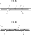
- FIG. 4B by providing unevennesses in the inter-cell connecting film, the outer film can be shaped so as not to stretch, as shown in FIG. 2D , when making the meandering fold.
- the size of the inter-cell connecting film is not limited as long as it allows the battery cells to be sandwiched therebetween. Since it is not necessary to be extremely large as compared with the battery cell, for example, the size may be the position of 0.1 mm to 5.0 mm from the end of the battery cell. When the battery exterior body can be insulated by other than the inter-cell connecting film, the size of the inter-cell connecting film may be smaller than that of the battery cell. When a terminal is provided at an end of the inter-cell connecting film, the inter-cell connecting film may be lengthened as necessary.
- the thickness of the inter-cell connecting film may be appropriately set in consideration of the balance of the required flexibility and strength.
- the thickness of the conductive surface side may be, for example, 0.005mm or more, 0.01mm or more, or 0.02mm or more.
- the thickness of the conductive surface side may be, for example, 0.10mm or less, 0.09mm or less, or 0.08mm or less.
- the thickness of the insulating surface side may be, for example, 0.005mm or more, 0.01mm or more, or 0.02 or more.
- the thickness of the insulating surface side may be, for example, 0.10mm or less, 0.09mm or less, or 0.08mm or less.
- a shrink film, a constraining band, an adhesive, ultrasonic welding, laser welding, electric welding, or the like may be used.
- the inter-cell connecting film may be sandwiched and fixed by a plate or the like from the outside of the inter-cell connecting film.
- the battery cells may be contacted with the inter-cell connecting film using a spring or the like.
- FIGs. 3A to 3D show an example in which a conductive pattern is formed on one side of an inter-cell connecting film.
- FIG. 3A is an example formed on the entire surface of the insulating substrate
- FIGs. 3B to 3D are examples in which a conductive pattern is formed on a part of the surface of the insulating substrate. Note that in FIGs. 3A to 3D , the insulating substrate is not shown.
- the positive electrode terminal portion of the exterior body of the plurality of battery cells may be in contact with the first conductive pattern, and the negative electrode terminal portion of the exterior body of the plurality of battery cells may be in contact with the second conductive pattern, whereby each of the plurality of battery cells may be electrically connected in parallel to one another.
- FIGs. 5A and 5B schematically illustrate a first connection embodiment of the present disclosure in which each of a plurality of battery cells are electrically connected in parallel to one another.
- FIG. 5A is a schematic view of the assembled battery 1 of the present disclosure viewed from the side
- FIG. 5B is a schematic view of the assembled battery 1 of the present disclosure viewed from the upper surface.
- the first inter-cell connecting film 21 and the second inter-cell connecting film 22 are respectively composed of only the first conductive pattern 21a and the second conductive pattern 22a, and the four battery cells 11a, 11b, 11c, 11d are electrically connected to the first conductive pattern 21a and the second conductive pattern 22a.
- a hole 21c is provided (only the hole of the first conductive pattern 21a is illustrated in FIG. 5B ) and serve as a terminal.
- the upper side of each battery cell 11 (the side described as "+" in FIG. 5A ) is a positive electrode
- the lower side (the side described as "-" in FIG. 5A ) is a negative electrode
- each of the battery cells is connected in parallel to one another.
- FIG. 6 shows a second connection embodiment of the present disclosure in which each of a plurality of battery cells are electrically connected in parallel to one another.
- the first inter-cell connecting film 21 is composed of the first conductive pattern 21a and the first insulating substrate 21b
- the second inter-cell connecting film 22 is composed of the second conductive pattern 22a and the first insulating substrate 22b.
- the four cells 11a, 11b, 11c, 11d are connected in parallel to each other as in the first embodiment.
- the positive electrode terminal portion of the exterior body of the first group of the plurality of battery cells and the negative electrode terminal portion of the exterior body of the second group of the plurality of battery cells may be in contact with the first conductive pattern, and the positive electrode terminal portion of the exterior body of the second group of the plurality of battery cells and the negative electrode terminal portion of the exterior body of the first group of the plurality of battery cells may be in contact with the second conductive pattern, whereby each of the plurality of battery cells may be electrically connected in series or connected in series and connected in parallel with one another.
- the first conductive patterned 21a is contacted with a positive electrode terminal portion of the exterior body of the battery cells 11a, 11c in the first group and a negative electrode terminal portion of the exterior body of the battery cells 11b, 11d in the second group.
- the second conductive patterned 22b contacts the positive electrode terminal portion of the exterior body of the battery cells 11b, 11d in the second group and the negative electrode terminal portion of the exterior body of the battery cells 11a, 11c in the first group.
- the first conductive pattern and the second conductive pattern may not be continuous, respectively.
- the first conductive pattern 21a and the second conductive pattern 22a are not continuous.
- the battery cells 11a, 11b, 11c, 11d are electrically connected continuously by changing the orientation of the battery cells 11 and contacting the respective conductive patterns.
- the battery cells are connected in series with each other.
- a series connection and a parallel connection may be mixed.
- the positive electrode terminal portions of the exterior bodies of the battery cells 11a, 11b in the first group and the negative electrode terminal portions of the exterior bodies of the battery cells 11c, 11d in the second group are contacted with the first conductive patterned 21a.
- the second conductive patterned 22b contacts the positive electrode terminal portions of the exterior bodies of the battery cells 11c, 11d in the second group and the negative electrode terminal portions of the exterior bodies of the battery cells 11a, 11b in the first group.
- battery cells 11a, 11b of the first group are connected in parallel and battery cells 11c, 11d of the second group of are connected in parallel. Each group in which the battery cells are connected in parallel is connected in series.
- the arrangement of the battery cells is not limited to a linear shape, and can be freely arranged such as a rectangular shape, an L-shape, a U-shape, a T-shape, or the like. Also in this respect, the restriction on the place where the assembled battery is arranged is reduced.
- FIG. 10A shows a rectangular arrangement
- FIG. 10B shows an L-shaped arrangement
- FIG. 10C shows a U-shaped arrangement
- FIG. 10D shows a T-shaped arrangement.
Landscapes
- Chemical & Material Sciences (AREA)
- Chemical Kinetics & Catalysis (AREA)
- Electrochemistry (AREA)
- General Chemical & Material Sciences (AREA)
- Engineering & Computer Science (AREA)
- Manufacturing & Machinery (AREA)
- Connection Of Batteries Or Terminals (AREA)
- Battery Mounting, Suspending (AREA)
- Sealing Battery Cases Or Jackets (AREA)
- Secondary Cells (AREA)
Abstract
An assembled battery comprising battery cells (11), a first and a second inter-cell connecting films having a first and a second conductive patterns, respectively, each of battery cells including a conductive exterior body housing an electrode body in the interior, the exterior body having a positive (111a) and a negative (111b )electrode terminal portions electrically connected to the positive and the negative electrodes of the electrode body, respectively, wherein one of the positive and negative electrode terminal portions of the exterior body of each of battery cells is in contact with the first conductive pattern, so that the other is in contact with the second conductive pattern, each of battery cells is sandwiched by the first and the second inter-cell connecting films, whereby via the first and the second conductive patterns, each of battery cells are electrically connected in parallel and/or in series with each other.
Description
- The present disclosure relates to an assembled battery.
- A conventional assembled battery includes a plurality of battery cells which are electrically connected.
-
Patent Literature 1 discloses a battery system assembled to a battery block such that a battery block formed by stacking a plurality of battery cells and electrodes of the battery cells are electrically connected to a bus bar provided on a flexible printed circuit board. - [Patent Literature 1]
JP 2014-086246 A - A conventional method of electrically connecting a plurality of battery cells includes fastening structure using bolts. However, the authors of the present disclosure have found that it is preferable to connect the battery cells with a film.
- An assembled battery, wherein
- the assembled battery comprises a plurality of battery cells, a first inter-cell connecting film, and a second inter-cell connecting film;
- each of the plurality of battery cells includes a conductive exterior body and an electrode body housed in the interior of the exterior body;
- the exterior body has a positive electrode terminal portion electrically connected to the positive electrode of the electrode body, and a negative electrode terminal portion electrically connected to the negative electrode of the electrode body;
- the first inter-cell connecting film has a first conductive pattern;
- the second inter-cell connecting film has a second conductive pattern; and
- one of the positive electrode terminal portion and the negative electrode terminal portion of the exterior body of each of the plurality of battery cells is in contact with the first conductive pattern, so that the other is in contact with the second conductive pattern, each of the plurality of battery cells is sandwiched by the first inter-cell connecting film and the second inter-cell connecting film, whereby via the first conductive pattern and the second conductive pattern, each of the plurality of battery cells is electrically connected in parallel and/or in series with one another.
- The assembled battery according to
embodiment 1, wherein - the positive electrode terminal portion of the exterior body of the plurality of battery cells contacts the first conductive pattern, and
- the negative electrode terminal portion of the exterior body of the plurality of battery cells is in contact with the second conductive pattern,
- whereby each of the plurality of battery cells is electrically connected in parallel to one another.
- The assembled battery according to
embodiment 1, wherein - in the first conductive pattern, the positive electrode terminal portion of the exterior body of the battery cell of the first group of the plurality of battery cells and the negative electrode terminal portion of the exterior body of the battery cell of the second group of the plurality of battery cells are in contact with each other,
- the positive electrode terminal portion of the exterior body of the battery cell of the second group of the plurality of battery cells and the negative electrode terminal portion of the exterior body of the battery cell of the first group of the plurality of battery cells in contact with the second conductive pattern,
- whereby, at least a portion of the plurality of battery cells is electrically connected in series with one another.
- The assembled battery according to
embodiment 1, wherein a cross-sectional shape of the exterior body on the positive electrode side and/or the exterior body on the negative electrode side of the battery cell is U-shaped. - The assembled battery according to any one of
embodiments 1 to 4, wherein the first inter-cell connecting film has a first conductive pattern, and a first insulating substrate supporting the first conductive pattern; and the second inter-cell connecting film has a second conductive pattern, and a second insulating substrate supporting the second conductive pattern. - The assembled battery according to embodiment 5, wherein the first conductive pattern and the second conductive pattern are metal, and the first insulating substrate and the second insulating substrate are resin.
- The assembled battery according to any one of
embodiments 1 to 6, wherein a cooling layer is laminated on one or both of a surface opposite to a surface in contact with the positive electrode terminal portion or the negative electrode terminal portion of the first inter-cell connecting film and a surface opposite to a surface in contact with the positive electrode terminal portion or the negative electrode terminal portion of the second inter-cell connecting film. - The assembled battery according to any one of
embodiments 1 to 7, wherein one or both of the first inter-cell connecting film and the second inter-cell connecting film has a positioning portion, and each of the plurality of battery cells is positioned by the positioning portion. - According to the present disclosure, it is possible to provide an assembled battery in which battery cells are connected by a film.
-
-
FIG. 1 is a schematic view of a battery cell included in the assembled battery of the present disclosure. -
FIGs. 2A to 2D are diagrams showing an example of the degree of freedom of the shape of the assembled battery as a whole of the present disclosure. -
FIGs. 3A to 3D are schematic diagrams of a conductive pattern in the assembled battery of the present disclosure. -
FIGs. 4A and 4B are schematic views of a positioning portion in the assembled battery of the present disclosure. -
FIGs. 5A and 5B are schematic diagrams of a first connection embodiment of the assembled battery of the present disclosure. -
FIG. 6 is a schematic diagram of a second connection embodiment of the assembled battery of the present disclosure. -
FIG. 7 is a schematic diagram of a third connection embodiment of the assembled battery of the present disclosure. -
FIG. 8 is a schematic diagram of a fourth connection embodiment of the assembled battery of the present disclosure. -
FIGs. 9A and 9B are diagram showings an example of an arrangement of battery cells in a plane direction in the assembled battery of the present disclosure. -
FIGs. 10A to 10D are diagrams showing another example of an arrangement of battery cells in a plane direction in the assembled battery of the present disclosure. - Hereinafter, the present disclosure will be described in detail with reference to the drawings. However, the present disclosure is not limited to this embodiment.
- The assembled battery of the present disclosure comprises a plurality of battery cells, a first inter-cell connecting film, and a second inter-cell connecting film.
- In the assembled battery of the present disclosure, a plurality of exterior bodies have a positive electrode terminal portion electrically connected to the positive electrode of the electrode body, and a negative electrode terminal portion electrically connected to the negative electrode of the electrode body, the first inter-cell connecting film has a first conductive pattern, and the second inter-cell connecting film has a second conductive pattern.
- Further, in the assembled battery of the present disclosure, one of the positive electrode terminal portion and the negative electrode terminal portion of the exterior body of each of the plurality of battery cells is in contact with the first conductive pattern and the other is in contact with the second conductive pattern, and each of the plurality of battery cells is sandwiched between the first inter-cell connecting film and the second inter-cell connecting film, whereby each of the plurality of battery cells is electrically connected in parallel and/or in series with one another via the first conductive pattern and the second conductive pattern.
- According to the assembled battery of the present disclosure, by connecting a plurality of battery cells in contact with a film having a directly conductive pattern, it is possible to electrically connect a plurality of battery cells even when fastening by bolts, nuts, or the like is not used. As a result, the space occupied by the assembled battery can be reduced, and the structural efficiency of the assembled battery can be improved. Further, since bolts, nuts, and the like are not required, the weight of the assembled battery can be reduced. However, if necessary, the assembled battery of the present disclosure may have a bolt, a nut, or the like.
- Further, in the assembled battery of the present disclosure, the plurality of battery cells can be connected to each other by freely selecting, for example, a series connection, a parallel connection, or a connection in which a series connection and a parallel connection are mixed.
- The configuration of the assembled battery of the present disclosure, the connection type of the battery cells, and the arrangement of the battery cells in the plane direction will be described below.
- The assembled battery of the present disclosure comprises a plurality of battery cells, and each of the plurality of battery cells includes a conductive exterior body and an electrode body accommodated in the interior of the exterior body. The exterior body has a positive electrode terminal portion electrically connected to the positive electrode of the electrode body and a negative electrode terminal portion electrically connected to the negative electrode of the electrode body.
- Specifically, for example, as shown in
FIG. 1 , thebattery cell 11 includes an exterior body and anelectrode body 112 accommodated in the interior of the exterior body. Theexterior body 111a on the positive electrode side of the electrode body has a conductive positive-electrode terminal portion electrically connected to the positive electrode of the electrode body, and theexterior body 111b on the negative-electrode-side of the electrode body has a conductive negative-electrode terminal portion electrically connected to the negative electrode of the electrode body. - The plurality of battery cells may be, for example, lithium-ion battery cells or nickel-metal hydride battery cells. The
exterior bodies - Insulating
portions exterior body 111a on the positive electrode side of the electrode body and theexterior body 111b on the negative electrode side of the electrode body, and on the side surface of theelectrode body 112, in order to insulate theexterior body 111a on the positive electrode side of the electrode body, theexterior body 111b on the negative electrode side of the electrode body, and the side surface of theelectrode body 112, and in order to seal theelectrode body 112. The insulatingportions - In the embodiment shown in
FIG. 1 , both theexterior body 111a on the positive electrode side of the electrode body and theexterior body 11 1b on the negative electrode side of the electrode body have a U-shaped or concave cross-sectional shape. It is possible that only one of theexterior bodies - Hereinafter, the prevention of intrusion of moisture will be described in more detail. The metallic material used for the
exterior bodies part - Therefore, as shown in
FIG. 1 , for both theexterior body 111a on the positive electrode side of the electrode body and theexterior body 111b on the negative electrode side of the electrode body, when the cross-sectional shape is U-shaped and there is a portion where theexterior bodies - The size of the battery cell is not particularly limited. For example, it may be 20mm×20mm or more, 30mm×30mm or more, 40mm×40mm or more, or 50mm×50mm or more. The shape of the battery cell is not limited to a square. The size of the battery cell may be, for example, 200mm×500mm or less, 200mm×300mm or less, 200mm×200mm or less, 150mm×150mm or less, or 100mm×100mm or less. The thickness of the battery cell can be, for example, 2.0mm or more, 2.5mm or more, or 3.0mm or more. The thickness of the battery cell may be, for example, 30.0mm or less, 20mm or less, 10mm or less, or 5.0mm or less. The distance between the battery cell and the battery cell may be, for example, 0.1mm or more, 0.3mm or more, or 0.5mm or more. The distance between the battery cell and the battery cell may be, for example, 5.0mm or less, 4.0mm or less, or 3.0mm or less.
- The assembled battery of the present disclosure includes a first inter-cell connecting film and a second inter-cell connecting film. The first inter-cell connecting film has a first conductive pattern, and the second inter-cell connecting film has a second conductive pattern. In the following description, the first inter-cell connecting film and the second inter-cell connecting film are collectively referred to simply as "inter-cell connecting film". The first conductive pattern and the second conductive pattern are also collectively referred to simply as a "conductive pattern".
- The inter-cell connecting film may be composed of only a conductive pattern. Alternatively, the first inter-cell connecting film may have a first conductive pattern and a first insulating substrate supporting the first conductive pattern, and the second inter-cell connecting film may have a second conductive pattern and a second insulating substrate supporting the second conductive pattern. In the following description, the first insulating substrate and the second insulating substrate are collectively simply referred to as "insulating substrate". The conductive pattern may be formed only on a part of the surface of the insulating substrate or may be formed on the entire surface of the insulating substrate. When the insulating substrate is provided, the assembled battery can be electrically insulated from the outside of the assembled battery, so that the possibility of electric leakage or the like is reduced, and the electrical performance can be improved.
- The first conductive pattern and the second conductive pattern may be metal, for example, gold, silver, copper, aluminum, an alloy containing one or more of the foregoing, or the like. The first insulating substrate and the second insulating substrate may be resins, such as polyethylene terephthalate, nylon, polymethyl methacrylate, polypropylene, polycarbonate, polyalkylene terephthalate, polyimide, epoxy resin, and the like.
- Further, by making the inter-cell connecting film flexible, the shape of the assembled battery as a whole can be freely changed. As a result, the restriction on the place where the assembled battery is arranged is reduced.
FIGs. 2A to 2D show an example in which the shape of the assembled battery of the present disclosure is changed. The assembled battery of the present disclosure can be bent as shown inFIG. 2A and FIG. 2B by making the inter-cell connecting film flexible. Further, as shown inFIG. 2C and FIG. 2D , it is possible to make the meandering fold. When making the meandering fold, as shown inFIG. 2C , the outer film needs to be stretched. As shown inFIG. 4B , by providing unevennesses in the inter-cell connecting film, the outer film can be shaped so as not to stretch, as shown inFIG. 2D , when making the meandering fold. - The size of the inter-cell connecting film is not limited as long as it allows the battery cells to be sandwiched therebetween. Since it is not necessary to be extremely large as compared with the battery cell, for example, the size may be the position of 0.1 mm to 5.0 mm from the end of the battery cell. When the battery exterior body can be insulated by other than the inter-cell connecting film, the size of the inter-cell connecting film may be smaller than that of the battery cell. When a terminal is provided at an end of the inter-cell connecting film, the inter-cell connecting film may be lengthened as necessary.
- The thickness of the inter-cell connecting film may be appropriately set in consideration of the balance of the required flexibility and strength. The thickness of the conductive surface side may be, for example, 0.005mm or more, 0.01mm or more, or 0.02mm or more. The thickness of the conductive surface side may be, for example, 0.10mm or less, 0.09mm or less, or 0.08mm or less. The thickness of the insulating surface side may be, for example, 0.005mm or more, 0.01mm or more, or 0.02 or more. The thickness of the insulating surface side may be, for example, 0.10mm or less, 0.09mm or less, or 0.08mm or less.
- As a method of contacting the battery cell with the inter-cell connecting film, a shrink film, a constraining band, an adhesive, ultrasonic welding, laser welding, electric welding, or the like may be used. Alternatively, as a method of contacting the battery cells with the inter-cell connecting film, the inter-cell connecting film may be sandwiched and fixed by a plate or the like from the outside of the inter-cell connecting film. Alternatively, the battery cells may be contacted with the inter-cell connecting film using a spring or the like.
-
FIGs. 3A to 3D show an example in which a conductive pattern is formed on one side of an inter-cell connecting film.FIG. 3A is an example formed on the entire surface of the insulating substrate, andFIGs. 3B to 3D are examples in which a conductive pattern is formed on a part of the surface of the insulating substrate. Note that inFIGs. 3A to 3D , the insulating substrate is not shown. - One or both of the first inter-cell connecting film and the second inter-cell connecting film optionally have a positioning portion, and each of the plurality of battery cells may be positioned by the positioning portion.
FIGs. 4A and 4B are a diagram schematically showing the assembledbattery 1 in which thepositioning portion 31 is provided in the firstinter-cell connecting film 21. By providing the positioning portion, it is possible to obtain an assembled battery in which the battery cells are accurately positioned and excellent in performance such as durability. The positioning portion may be, for example, a resin as shown inFIG. 4A . The inter-cell connecting film may be notched without using a resin or the like, or the inter-cell connecting film may be bent into an uneven shape as shown inFIG. 4B to form a positioning portion. When the inter-cell connecting film is bent into an uneven shape to form a positioning portion, it can be adjusted so that the outer film does not need to be stretched, as shown inFIG. 2D , when the assembled battery is meandering folded. The thickness of the positioning portion is thinner than that of the battery cell. The thickness of the positioning portion may be, for example, 0.02mm or more, 0.03mm or more, or 0.05mm or more. The thickness of the positioning portion may be, for example, 0.50mm or less, 0.40mm or less, or 0.30mm or less. - In the assembled battery of the present disclosure, a cooling layer may be optionally laminated on one or both surfaces of a surface opposite to a surface in contact with the positive electrode terminal portion or the negative electrode terminal portion of the first inter-cell connecting film and a surface opposite to a surface in contact with the positive electrode terminal portion or the negative electrode terminal portion of the second inter-cell connecting film. As the cooling layer, for example, an aluminum plate may be integrally provided on the outside of the inter-cell connecting film. Thereby, it is possible to obtain an assembled battery having excellent cooling performance.
- In the assembled battery of the present disclosure, each of the plurality of battery cells is sandwiched between the first inter-cell connecting film and the second inter-cell connecting film such that one of the positive electrode terminal portion and the negative electrode terminal portion of the exterior body of each of the plurality of battery cells contacts the first conductive pattern and the other contacts the second conductive pattern. Each of the plurality of battery cells is electrically connected in parallel and/or in series with one another via the first conductive pattern and the second conductive pattern. The end portion of the inter-cell connecting film may be provided with a hole and serve as a terminal.
- Hereinafter, the electrical connection of the battery cells in the assembled battery of the present disclosure will be described with reference to the drawings showing the schematic of specific embodiments. The electrical connection of the present disclosure is not limited to the following embodiments.
- First, an example in which each of the plurality of battery cells is electrically connected in parallel to one another will be described.
- In the assembled battery of the present disclosure, the positive electrode terminal portion of the exterior body of the plurality of battery cells may be in contact with the first conductive pattern, and the negative electrode terminal portion of the exterior body of the plurality of battery cells may be in contact with the second conductive pattern, whereby each of the plurality of battery cells may be electrically connected in parallel to one another.
-
FIGs. 5A and 5B schematically illustrate a first connection embodiment of the present disclosure in which each of a plurality of battery cells are electrically connected in parallel to one another. -
FIG. 5A is a schematic view of the assembledbattery 1 of the present disclosure viewed from the side, andFIG. 5B is a schematic view of the assembledbattery 1 of the present disclosure viewed from the upper surface. - In the assembled
battery 1 shown inFIGs. 5A and 5B , the firstinter-cell connecting film 21 and the secondinter-cell connecting film 22 are respectively composed of only the firstconductive pattern 21a and the secondconductive pattern 22a, and the fourbattery cells conductive pattern 21a and the secondconductive pattern 22a. At the end portions of the firstconductive pattern 21a and the secondconductive pattern 22a, ahole 21c is provided (only the hole of the firstconductive pattern 21a is illustrated inFIG. 5B ) and serve as a terminal. In the embodiment shown inFIGs. 5A and 5B , the upper side of each battery cell 11 (the side described as "+" inFIG. 5A ) is a positive electrode, the lower side (the side described as "-" inFIG. 5A ) is a negative electrode, and each of the battery cells is connected in parallel to one another. -
FIG. 6 shows a second connection embodiment of the present disclosure in which each of a plurality of battery cells are electrically connected in parallel to one another. In the embodiment shown inFIG. 6 , the firstinter-cell connecting film 21 is composed of the firstconductive pattern 21a and the first insulatingsubstrate 21b, and the secondinter-cell connecting film 22 is composed of the secondconductive pattern 22a and the first insulatingsubstrate 22b. The fourcells - Next, an example in which each of the plurality of battery cells is electrically connected in series and an example in which a series connection and a parallel connection are mixed will be described.
- In the assembled battery of the present disclosure, the positive electrode terminal portion of the exterior body of the first group of the plurality of battery cells and the negative electrode terminal portion of the exterior body of the second group of the plurality of battery cells may be in contact with the first conductive pattern, and the positive electrode terminal portion of the exterior body of the second group of the plurality of battery cells and the negative electrode terminal portion of the exterior body of the first group of the plurality of battery cells may be in contact with the second conductive pattern, whereby each of the plurality of battery cells may be electrically connected in series or connected in series and connected in parallel with one another.
-
FIG. 7 shows a third connection embodiment of the present disclosure in which each of a plurality of battery cells are electrically connected in series with one another. - In the embodiment schematically shown in
FIG. 7 , the first conductive patterned 21a is contacted with a positive electrode terminal portion of the exterior body of thebattery cells battery cells battery cells battery cells FIG. 7 , in the assembled battery of the present disclosure, the first conductive pattern and the second conductive pattern may not be continuous, respectively. In the embodiment shown inFIG. 7 , the firstconductive pattern 21a and the secondconductive pattern 22a are not continuous. However, thebattery cells battery cells 11 and contacting the respective conductive patterns. In the assembled battery shown inFIG. 7 , the battery cells are connected in series with each other. -
FIG. 8 shows a fourth connection embodiment of the present disclosure in which each of a plurality of battery cells are electrically connected in series and in parallel with one another. - As in the embodiment schematically shown in
FIG. 8 , a series connection and a parallel connection may be mixed. In the embodiment shown inFIG. 8 , the positive electrode terminal portions of the exterior bodies of thebattery cells battery cells battery cells battery cells FIG. 8 ,battery cells battery cells - The assembled battery of the present disclosure is configured by sandwiching a plurality of battery cells by inter-cell connecting films. Therefore, the number of battery cells to be connected is not limited, and any number of battery cells can be connected.
FIG. 9A is a schematic diagram of an example in which three battery cells are connected, andFIG. 9B is a schematic diagram of an embodiment in which six battery cells are connected. - The arrangement of the battery cells is not limited to a linear shape, and can be freely arranged such as a rectangular shape, an L-shape, a U-shape, a T-shape, or the like. Also in this respect, the restriction on the place where the assembled battery is arranged is reduced.
FIG. 10A shows a rectangular arrangement,FIG. 10B shows an L-shaped arrangement,FIG. 10C shows a U-shaped arrangement, andFIG. 10D shows a T-shaped arrangement. -
- 1 Battery pack
- 11, 11a, 11b, 11c, 11d Cell
- 111a, 111b Exterior body
- 113a, 113b Insulating part
- 21 First inter-cell connecting film
- 21a First conductive pattern
- 21b First insulating substrate
- 21c Hole
- 22 Second inter-cell connecting film
- 22a Second conductive pattern
- 22b Second insulating substrate
- 31 Positioning part
Claims (8)
- An assembled battery, whereinthe assembled battery comprises a plurality of battery cells, a first inter-cell connecting film, and a second inter-cell connecting film;each of the plurality of battery cells includes a conductive exterior body and an electrode body housed in the interior of the exterior body;the exterior body has a positive electrode terminal portion electrically connected to the positive electrode of the electrode body, and a negative electrode terminal portion electrically connected to the negative electrode of the electrode body;the first inter-cell connecting film has a first conductive pattern;the second inter-cell connecting film has a second conductive pattern; andone of the positive electrode terminal portion and the negative electrode terminal portion of the exterior body of each of the plurality of battery cells is in contact with the first conductive pattern, so that the other is in contact with the second conductive pattern, each of the plurality of battery cells is sandwiched by the first inter-cell connecting film and the second inter-cell connecting film, whereby via the first conductive pattern and the second conductive pattern, each of the plurality of battery cells is electrically connected in parallel and/or in series with one another.
- The assembled battery according to claim 1, whereinthe positive electrode terminal portion of the exterior body of the plurality of battery cells contacts the first conductive pattern, andthe negative electrode terminal portion of the exterior body of the plurality of battery cells is in contact with the second conductive pattern,whereby each of the plurality of battery cells is electrically connected in parallel to one another.
- The assembled battery according to claim 1, whereinin the first conductive pattern, the positive electrode terminal portion of the exterior body of the battery cell of the first group of the plurality of battery cells and the negative electrode terminal portion of the exterior body of the battery cell of the second group of the plurality of battery cells are in contact with each other,the positive electrode terminal portion of the exterior body of the battery cell of the second group of the plurality of battery cells and the negative electrode terminal portion of the exterior body of the battery cell of the first group of the plurality of battery cells in contact with the second conductive pattern,whereby, at least a portion of the plurality of battery cells is electrically connected in series with one another.
- The assembled battery according to any one of claims 1 to 3, wherein a cross-sectional shape of the exterior body on the positive electrode side and/or the exterior body on the negative electrode side of the battery cell is U-shaped.
- The assembled battery according to any one of claims 1 to 4, wherein the first inter-cell connecting film has a first conductive pattern, and a first insulating substrate supporting the first conductive pattern; and the second inter-cell connecting film has a second conductive pattern,
and a second insulating substrate supporting the second conductive pattern. - The assembled battery according to claim 5, wherein the first conductive pattern and the second conductive pattern are metal, and the first insulating substrate and the second insulating substrate are resin.
- The assembled battery according to any one of claims 1 to 4, wherein a cooling layer is laminated on one or both of a surface opposite to a surface in contact with the positive electrode terminal portion or the negative electrode terminal portion of the first inter-cell connecting film and a surface opposite to a surface in contact with the positive electrode terminal portion or the negative electrode terminal portion of the second inter-cell connecting film.
- The assembled battery according to any one of claims 1 to 4, wherein one or both of the first inter-cell connecting film and the second inter-cell connecting film has a positioning portion, and each of the plurality of battery cells is positioned by the positioning portion.
Applications Claiming Priority (1)
| Application Number | Priority Date | Filing Date | Title |
|---|---|---|---|
| JP2023065874A JP2024151998A (en) | 2023-04-13 | 2023-04-13 | Battery pack |
Publications (1)
| Publication Number | Publication Date |
|---|---|
| EP4451426A1 true EP4451426A1 (en) | 2024-10-23 |
Family
ID=90473316
Family Applications (1)
| Application Number | Title | Priority Date | Filing Date |
|---|---|---|---|
| EP24165945.7A Pending EP4451426A1 (en) | 2023-04-13 | 2024-03-25 | Assembled battery |
Country Status (5)
| Country | Link |
|---|---|
| US (1) | US20240347867A1 (en) |
| EP (1) | EP4451426A1 (en) |
| JP (1) | JP2024151998A (en) |
| KR (1) | KR20240152746A (en) |
| CN (1) | CN118801015A (en) |
Citations (6)
| Publication number | Priority date | Publication date | Assignee | Title |
|---|---|---|---|---|
| JP2014086246A (en) | 2012-10-23 | 2014-05-12 | Nippon Mektron Ltd | Flexible printed wiring board with bus bar, and method of manufacturing the same, and battery system |
| US20160372718A1 (en) * | 2015-06-19 | 2016-12-22 | Intel Corporation | Fabric battery |
| US20170069940A1 (en) * | 2014-03-06 | 2017-03-09 | Unicell Llc | Battery cells and arrangements |
| US20180131053A1 (en) * | 2015-04-10 | 2018-05-10 | Robert Bosch Gmbh | Method and device for temperature regulation of battery cells and vehicle |
| CN108232050A (en) * | 2018-03-15 | 2018-06-29 | 深圳前海优容科技有限公司 | A kind of battery, battery pack and electric vehicle |
| WO2022086799A1 (en) * | 2020-10-19 | 2022-04-28 | Duracell U.S. Operations, Inc. | Conformable battery pack assembly |
Family Cites Families (4)
| Publication number | Priority date | Publication date | Assignee | Title |
|---|---|---|---|---|
| JP5357373B2 (en) * | 2004-03-19 | 2013-12-04 | 富士重工業株式会社 | Planar alignment structure of power storage unit |
| FR3007895B1 (en) * | 2013-06-27 | 2015-06-19 | Valeo Systemes Thermiques | ELECTROCHEMICAL CELL STRIP FOR REALIZING A BATTERY MODULE FOR AN ELECTRIC OR HYBRID VEHICLE, AND METHOD OF MAKING SUCH A MODULE |
| JP6587838B2 (en) * | 2015-06-11 | 2019-10-09 | 三洋化成工業株式会社 | Lithium ion batteries and wearable electronic devices |
| WO2018092640A1 (en) * | 2016-11-21 | 2018-05-24 | 昭和電工パッケージング株式会社 | High power battery and battery case |
-
2023
- 2023-04-13 JP JP2023065874A patent/JP2024151998A/en active Pending
-
2024
- 2024-03-25 EP EP24165945.7A patent/EP4451426A1/en active Pending
- 2024-03-27 US US18/617,835 patent/US20240347867A1/en active Pending
- 2024-04-10 CN CN202410424643.2A patent/CN118801015A/en active Pending
- 2024-04-11 KR KR1020240048726A patent/KR20240152746A/en active Pending
Patent Citations (6)
| Publication number | Priority date | Publication date | Assignee | Title |
|---|---|---|---|---|
| JP2014086246A (en) | 2012-10-23 | 2014-05-12 | Nippon Mektron Ltd | Flexible printed wiring board with bus bar, and method of manufacturing the same, and battery system |
| US20170069940A1 (en) * | 2014-03-06 | 2017-03-09 | Unicell Llc | Battery cells and arrangements |
| US20180131053A1 (en) * | 2015-04-10 | 2018-05-10 | Robert Bosch Gmbh | Method and device for temperature regulation of battery cells and vehicle |
| US20160372718A1 (en) * | 2015-06-19 | 2016-12-22 | Intel Corporation | Fabric battery |
| CN108232050A (en) * | 2018-03-15 | 2018-06-29 | 深圳前海优容科技有限公司 | A kind of battery, battery pack and electric vehicle |
| WO2022086799A1 (en) * | 2020-10-19 | 2022-04-28 | Duracell U.S. Operations, Inc. | Conformable battery pack assembly |
Also Published As
| Publication number | Publication date |
|---|---|
| CN118801015A (en) | 2024-10-18 |
| US20240347867A1 (en) | 2024-10-17 |
| KR20240152746A (en) | 2024-10-22 |
| JP2024151998A (en) | 2024-10-25 |
Similar Documents
| Publication | Publication Date | Title |
|---|---|---|
| US20220173484A1 (en) | Battery pack | |
| EP3944396B1 (en) | Secondary battery, electrode member thereof, battery module and related apparatus | |
| US8263255B2 (en) | Rechargeable battery and battery module | |
| US7501203B2 (en) | Battery formed of a stack of substantially rectangular electrodes | |
| US8906543B2 (en) | Battery having tab with insulator for electrode assembly | |
| KR100589347B1 (en) | Secondary battery | |
| KR100542238B1 (en) | Battery module | |
| KR102618844B1 (en) | Lead tabs for battery terminals | |
| KR102020757B1 (en) | Electrical energy storage module and method for producing an electrical energy storage module | |
| KR100823193B1 (en) | Secondary battery | |
| KR20180126534A (en) | Multi-joint battery module | |
| EP4068490B1 (en) | Battery cell, battery, electric device, and manufacturing method and device for battery cell | |
| EP4224621B1 (en) | Secondary battery and device including same | |
| JP7225795B2 (en) | power storage device | |
| US10276853B2 (en) | Electrode arrangement of a battery cell, electrode layer and battery cell and method for producing the latter | |
| US12381294B2 (en) | Electrode terminal and use thereof | |
| EP4451426A1 (en) | Assembled battery | |
| JP2023100001A (en) | power storage device | |
| CN120677588A (en) | Bus module and battery pack | |
| US20250149744A1 (en) | Assembled-battery structure and composite assembled-battery structure | |
| JP7262637B1 (en) | bipolar battery | |
| US20260112785A1 (en) | Bus bar assembly and battery module including the bus bar assembly | |
| KR102821399B1 (en) | Battery comprising a bipolar cell having a solid polymer peripheral edge insulator | |
| JP7786049B2 (en) | Power storage device | |
| CN120356945A (en) | Electrode plate, electrode assembly and rechargeable battery including the same |
Legal Events
| Date | Code | Title | Description |
|---|---|---|---|
| PUAI | Public reference made under article 153(3) epc to a published international application that has entered the european phase |
Free format text: ORIGINAL CODE: 0009012 |
|
| STAA | Information on the status of an ep patent application or granted ep patent |
Free format text: STATUS: REQUEST FOR EXAMINATION WAS MADE |
|
| 17P | Request for examination filed |
Effective date: 20240331 |
|
| AK | Designated contracting states |
Kind code of ref document: A1 Designated state(s): AL AT BE BG CH CY CZ DE DK EE ES FI FR GB GR HR HU IE IS IT LI LT LU LV MC ME MK MT NL NO PL PT RO RS SE SI SK SM TR |