EP4451369A1 - Fluoride-ion battery, negative electrode active material for fluoride-ion battery, and method for manufacturing negative electrode active material for fluoride-ion battery - Google Patents
Fluoride-ion battery, negative electrode active material for fluoride-ion battery, and method for manufacturing negative electrode active material for fluoride-ion battery Download PDFInfo
- Publication number
- EP4451369A1 EP4451369A1 EP24153869.3A EP24153869A EP4451369A1 EP 4451369 A1 EP4451369 A1 EP 4451369A1 EP 24153869 A EP24153869 A EP 24153869A EP 4451369 A1 EP4451369 A1 EP 4451369A1
- Authority
- EP
- European Patent Office
- Prior art keywords
- fluoride
- active material
- electrode active
- negative electrode
- ion battery
- Prior art date
- Legal status (The legal status is an assumption and is not a legal conclusion. Google has not performed a legal analysis and makes no representation as to the accuracy of the status listed.)
- Pending
Links
- KRHYYFGTRYWZRS-UHFFFAOYSA-M Fluoride anion Chemical compound [F-] KRHYYFGTRYWZRS-UHFFFAOYSA-M 0.000 title claims abstract description 60
- 239000007773 negative electrode material Substances 0.000 title claims abstract description 51
- 238000000034 method Methods 0.000 title claims description 14
- 238000004519 manufacturing process Methods 0.000 title claims description 10
- ORUIBWPALBXDOA-UHFFFAOYSA-L magnesium fluoride Chemical compound [F-].[F-].[Mg+2] ORUIBWPALBXDOA-UHFFFAOYSA-L 0.000 claims abstract description 52
- 229910001635 magnesium fluoride Inorganic materials 0.000 claims abstract description 49
- 239000011777 magnesium Substances 0.000 claims abstract description 39
- 239000007774 positive electrode material Substances 0.000 claims abstract description 31
- 229910052749 magnesium Inorganic materials 0.000 claims abstract description 21
- FYYHWMGAXLPEAU-UHFFFAOYSA-N Magnesium Chemical compound [Mg] FYYHWMGAXLPEAU-UHFFFAOYSA-N 0.000 claims abstract description 20
- 239000003792 electrolyte Substances 0.000 claims abstract description 15
- RZSYHFSPKJYEQZ-UHFFFAOYSA-J [F-].[F-].[F-].[F-].[Ca+2].[Ba+2] Chemical compound [F-].[F-].[F-].[F-].[Ca+2].[Ba+2] RZSYHFSPKJYEQZ-UHFFFAOYSA-J 0.000 claims abstract description 11
- 238000001228 spectrum Methods 0.000 claims description 16
- CETPSERCERDGAM-UHFFFAOYSA-N ceric oxide Chemical compound O=[Ce]=O CETPSERCERDGAM-UHFFFAOYSA-N 0.000 claims description 13
- 229910000422 cerium(IV) oxide Inorganic materials 0.000 claims description 12
- 229910016523 CuKa Inorganic materials 0.000 claims description 10
- 230000005855 radiation Effects 0.000 claims description 10
- 230000008859 change Effects 0.000 claims description 3
- 238000002441 X-ray diffraction Methods 0.000 description 29
- 230000000052 comparative effect Effects 0.000 description 17
- 239000000203 mixture Substances 0.000 description 16
- 239000011575 calcium Substances 0.000 description 14
- -1 fluoride ions Chemical class 0.000 description 14
- 238000002156 mixing Methods 0.000 description 12
- OKTJSMMVPCPJKN-UHFFFAOYSA-N Carbon Chemical compound [C] OKTJSMMVPCPJKN-UHFFFAOYSA-N 0.000 description 11
- 238000007599 discharging Methods 0.000 description 9
- 239000007784 solid electrolyte Substances 0.000 description 9
- 238000006243 chemical reaction Methods 0.000 description 8
- OYLGJCQECKOTOL-UHFFFAOYSA-L barium fluoride Chemical compound [F-].[F-].[Ba+2] OYLGJCQECKOTOL-UHFFFAOYSA-L 0.000 description 7
- 229910001632 barium fluoride Inorganic materials 0.000 description 7
- 239000011230 binding agent Substances 0.000 description 7
- 150000004673 fluoride salts Chemical class 0.000 description 7
- 238000005259 measurement Methods 0.000 description 7
- WUKWITHWXAAZEY-UHFFFAOYSA-L calcium difluoride Chemical compound [F-].[F-].[Ca+2] WUKWITHWXAAZEY-UHFFFAOYSA-L 0.000 description 6
- 150000002222 fluorine compounds Chemical class 0.000 description 6
- 239000006230 acetylene black Substances 0.000 description 5
- 229910001634 calcium fluoride Inorganic materials 0.000 description 5
- 238000003701 mechanical milling Methods 0.000 description 5
- 239000000843 powder Substances 0.000 description 5
- 239000003575 carbonaceous material Substances 0.000 description 4
- 229910001506 inorganic fluoride Inorganic materials 0.000 description 4
- 239000003960 organic solvent Substances 0.000 description 4
- HBBGRARXTFLTSG-UHFFFAOYSA-N Lithium ion Chemical compound [Li+] HBBGRARXTFLTSG-UHFFFAOYSA-N 0.000 description 3
- 239000011149 active material Substances 0.000 description 3
- 229910045601 alloy Inorganic materials 0.000 description 3
- 239000000956 alloy Substances 0.000 description 3
- 239000012300 argon atmosphere Substances 0.000 description 3
- 229910052788 barium Inorganic materials 0.000 description 3
- 229910052791 calcium Inorganic materials 0.000 description 3
- 230000000694 effects Effects 0.000 description 3
- 239000008151 electrolyte solution Substances 0.000 description 3
- 229910001416 lithium ion Inorganic materials 0.000 description 3
- 229910052751 metal Inorganic materials 0.000 description 3
- 239000004745 nonwoven fabric Substances 0.000 description 3
- 239000012925 reference material Substances 0.000 description 3
- 230000002441 reversible effect Effects 0.000 description 3
- ZUHZGEOKBKGPSW-UHFFFAOYSA-N tetraglyme Chemical compound COCCOCCOCCOCCOC ZUHZGEOKBKGPSW-UHFFFAOYSA-N 0.000 description 3
- ZZXUZKXVROWEIF-UHFFFAOYSA-N 1,2-butylene carbonate Chemical compound CCC1COC(=O)O1 ZZXUZKXVROWEIF-UHFFFAOYSA-N 0.000 description 2
- DSMUTQTWFHVVGQ-UHFFFAOYSA-N 4,5-difluoro-1,3-dioxolan-2-one Chemical compound FC1OC(=O)OC1F DSMUTQTWFHVVGQ-UHFFFAOYSA-N 0.000 description 2
- SBLRHMKNNHXPHG-UHFFFAOYSA-N 4-fluoro-1,3-dioxolan-2-one Chemical compound FC1COC(=O)O1 SBLRHMKNNHXPHG-UHFFFAOYSA-N 0.000 description 2
- 229910052684 Cerium Inorganic materials 0.000 description 2
- OIFBSDVPJOWBCH-UHFFFAOYSA-N Diethyl carbonate Chemical compound CCOC(=O)OCC OIFBSDVPJOWBCH-UHFFFAOYSA-N 0.000 description 2
- KMTRUDSVKNLOMY-UHFFFAOYSA-N Ethylene carbonate Chemical compound O=C1OCCO1 KMTRUDSVKNLOMY-UHFFFAOYSA-N 0.000 description 2
- 239000002033 PVDF binder Substances 0.000 description 2
- 239000004698 Polyethylene Substances 0.000 description 2
- 239000004743 Polypropylene Substances 0.000 description 2
- 238000004364 calculation method Methods 0.000 description 2
- 239000002041 carbon nanotube Substances 0.000 description 2
- 229910021393 carbon nanotube Inorganic materials 0.000 description 2
- 239000000969 carrier Substances 0.000 description 2
- 150000001768 cations Chemical class 0.000 description 2
- 239000013078 crystal Substances 0.000 description 2
- 230000003247 decreasing effect Effects 0.000 description 2
- 238000010586 diagram Methods 0.000 description 2
- 238000009792 diffusion process Methods 0.000 description 2
- 238000002848 electrochemical method Methods 0.000 description 2
- JBTWLSYIZRCDFO-UHFFFAOYSA-N ethyl methyl carbonate Chemical compound CCOC(=O)OC JBTWLSYIZRCDFO-UHFFFAOYSA-N 0.000 description 2
- 239000011888 foil Substances 0.000 description 2
- 239000002608 ionic liquid Substances 0.000 description 2
- 229910052745 lead Inorganic materials 0.000 description 2
- 239000007788 liquid Substances 0.000 description 2
- 229910052744 lithium Inorganic materials 0.000 description 2
- 239000000463 material Substances 0.000 description 2
- 229910052976 metal sulfide Inorganic materials 0.000 description 2
- 239000002245 particle Substances 0.000 description 2
- BASFCYQUMIYNBI-UHFFFAOYSA-N platinum Substances [Pt] BASFCYQUMIYNBI-UHFFFAOYSA-N 0.000 description 2
- 229920000573 polyethylene Polymers 0.000 description 2
- 239000002861 polymer material Substances 0.000 description 2
- 229920001155 polypropylene Polymers 0.000 description 2
- 229920001343 polytetrafluoroethylene Polymers 0.000 description 2
- 239000004810 polytetrafluoroethylene Substances 0.000 description 2
- 229920002981 polyvinylidene fluoride Polymers 0.000 description 2
- 229910052700 potassium Inorganic materials 0.000 description 2
- RUOJZAUFBMNUDX-UHFFFAOYSA-N propylene carbonate Chemical compound CC1COC(=O)O1 RUOJZAUFBMNUDX-UHFFFAOYSA-N 0.000 description 2
- 239000002994 raw material Substances 0.000 description 2
- 229910052701 rubidium Inorganic materials 0.000 description 2
- 229910052708 sodium Inorganic materials 0.000 description 2
- 229910052718 tin Inorganic materials 0.000 description 2
- XMWRBQBLMFGWIX-UHFFFAOYSA-N C60 fullerene Chemical compound C12=C3C(C4=C56)=C7C8=C5C5=C9C%10=C6C6=C4C1=C1C4=C6C6=C%10C%10=C9C9=C%11C5=C8C5=C8C7=C3C3=C7C2=C1C1=C2C4=C6C4=C%10C6=C9C9=C%11C5=C5C8=C3C3=C7C1=C1C2=C4C6=C2C9=C5C3=C12 XMWRBQBLMFGWIX-UHFFFAOYSA-N 0.000 description 1
- OYPRJOBELJOOCE-UHFFFAOYSA-N Calcium Chemical compound [Ca] OYPRJOBELJOOCE-UHFFFAOYSA-N 0.000 description 1
- 229910015484 FeFz Inorganic materials 0.000 description 1
- YCKRFDGAMUMZLT-UHFFFAOYSA-N Fluorine atom Chemical compound [F] YCKRFDGAMUMZLT-UHFFFAOYSA-N 0.000 description 1
- 239000003513 alkali Substances 0.000 description 1
- 150000001336 alkenes Chemical class 0.000 description 1
- 125000005210 alkyl ammonium group Chemical group 0.000 description 1
- HSFWRNGVRCDJHI-UHFFFAOYSA-N alpha-acetylene Natural products C#C HSFWRNGVRCDJHI-UHFFFAOYSA-N 0.000 description 1
- 229910052782 aluminium Inorganic materials 0.000 description 1
- XAGFODPZIPBFFR-UHFFFAOYSA-N aluminium Chemical compound [Al] XAGFODPZIPBFFR-UHFFFAOYSA-N 0.000 description 1
- 238000004458 analytical method Methods 0.000 description 1
- 150000001450 anions Chemical class 0.000 description 1
- 229910052787 antimony Inorganic materials 0.000 description 1
- DSAJWYNOEDNPEQ-UHFFFAOYSA-N barium atom Chemical compound [Ba] DSAJWYNOEDNPEQ-UHFFFAOYSA-N 0.000 description 1
- 229910052792 caesium Inorganic materials 0.000 description 1
- 239000006229 carbon black Substances 0.000 description 1
- 235000019241 carbon black Nutrition 0.000 description 1
- 229910052800 carbon group element Inorganic materials 0.000 description 1
- 150000005678 chain carbonates Chemical class 0.000 description 1
- 229910052804 chromium Inorganic materials 0.000 description 1
- 239000000571 coke Substances 0.000 description 1
- 239000004020 conductor Substances 0.000 description 1
- 229910052802 copper Inorganic materials 0.000 description 1
- 150000005676 cyclic carbonates Chemical class 0.000 description 1
- IEJIGPNLZYLLBP-UHFFFAOYSA-N dimethyl carbonate Chemical compound COC(=O)OC IEJIGPNLZYLLBP-UHFFFAOYSA-N 0.000 description 1
- 238000005516 engineering process Methods 0.000 description 1
- 229910052731 fluorine Inorganic materials 0.000 description 1
- 239000011737 fluorine Substances 0.000 description 1
- 229910003472 fullerene Inorganic materials 0.000 description 1
- 239000006232 furnace black Substances 0.000 description 1
- 229910052737 gold Inorganic materials 0.000 description 1
- 229910021389 graphene Inorganic materials 0.000 description 1
- 229910002804 graphite Inorganic materials 0.000 description 1
- 239000010439 graphite Substances 0.000 description 1
- 229910052742 iron Inorganic materials 0.000 description 1
- 239000003273 ketjen black Substances 0.000 description 1
- 229910052747 lanthanoid Inorganic materials 0.000 description 1
- 150000002602 lanthanoids Chemical class 0.000 description 1
- 229910052746 lanthanum Inorganic materials 0.000 description 1
- 229910052748 manganese Inorganic materials 0.000 description 1
- 229910052960 marcasite Inorganic materials 0.000 description 1
- 230000007246 mechanism Effects 0.000 description 1
- 239000002184 metal Substances 0.000 description 1
- 229910001512 metal fluoride Inorganic materials 0.000 description 1
- 229910044991 metal oxide Inorganic materials 0.000 description 1
- 150000004706 metal oxides Chemical class 0.000 description 1
- 150000002739 metals Chemical class 0.000 description 1
- 238000012986 modification Methods 0.000 description 1
- 230000004048 modification Effects 0.000 description 1
- 229910052759 nickel Inorganic materials 0.000 description 1
- JRZJOMJEPLMPRA-UHFFFAOYSA-N olefin Natural products CCCCCCCC=C JRZJOMJEPLMPRA-UHFFFAOYSA-N 0.000 description 1
- 229910052762 osmium Inorganic materials 0.000 description 1
- 229910052697 platinum Inorganic materials 0.000 description 1
- 229920003196 poly(1,3-dioxolane) Polymers 0.000 description 1
- 229920001197 polyacetylene Polymers 0.000 description 1
- 229920000767 polyaniline Polymers 0.000 description 1
- 229920000128 polypyrrole Polymers 0.000 description 1
- 229920000123 polythiophene Polymers 0.000 description 1
- 239000011148 porous material Substances 0.000 description 1
- NIFIFKQPDTWWGU-UHFFFAOYSA-N pyrite Chemical compound [Fe+2].[S-][S-] NIFIFKQPDTWWGU-UHFFFAOYSA-N 0.000 description 1
- 229910052683 pyrite Inorganic materials 0.000 description 1
- 229920005989 resin Polymers 0.000 description 1
- 239000011347 resin Substances 0.000 description 1
- 230000004044 response Effects 0.000 description 1
- 229910052703 rhodium Inorganic materials 0.000 description 1
- 229910052707 ruthenium Inorganic materials 0.000 description 1
- 229910052709 silver Inorganic materials 0.000 description 1
- 239000000243 solution Substances 0.000 description 1
- 239000002904 solvent Substances 0.000 description 1
- 229910052712 strontium Inorganic materials 0.000 description 1
- QEMXHQIAXOOASZ-UHFFFAOYSA-N tetramethylammonium Chemical compound C[N+](C)(C)C QEMXHQIAXOOASZ-UHFFFAOYSA-N 0.000 description 1
- 239000006234 thermal black Substances 0.000 description 1
- 229910052719 titanium Inorganic materials 0.000 description 1
- YFNKIDBQEZZDLK-UHFFFAOYSA-N triglyme Chemical compound COCCOCCOCCOC YFNKIDBQEZZDLK-UHFFFAOYSA-N 0.000 description 1
- 229910052720 vanadium Inorganic materials 0.000 description 1
- 229910052725 zinc Inorganic materials 0.000 description 1
Images




Classifications
-
- H—ELECTRICITY
- H01—ELECTRIC ELEMENTS
- H01M—PROCESSES OR MEANS, e.g. BATTERIES, FOR THE DIRECT CONVERSION OF CHEMICAL ENERGY INTO ELECTRICAL ENERGY
- H01M4/00—Electrodes
- H01M4/02—Electrodes composed of, or comprising, active material
- H01M4/36—Selection of substances as active materials, active masses, active liquids
- H01M4/362—Composites
-
- H—ELECTRICITY
- H01—ELECTRIC ELEMENTS
- H01M—PROCESSES OR MEANS, e.g. BATTERIES, FOR THE DIRECT CONVERSION OF CHEMICAL ENERGY INTO ELECTRICAL ENERGY
- H01M4/00—Electrodes
- H01M4/02—Electrodes composed of, or comprising, active material
- H01M4/13—Electrodes for accumulators with non-aqueous electrolyte, e.g. for lithium-accumulators; Processes of manufacture thereof
- H01M4/136—Electrodes based on inorganic compounds other than oxides or hydroxides, e.g. sulfides, selenides, tellurides, halogenides or LiCoFy
-
- C—CHEMISTRY; METALLURGY
- C01—INORGANIC CHEMISTRY
- C01F—COMPOUNDS OF THE METALS BERYLLIUM, MAGNESIUM, ALUMINIUM, CALCIUM, STRONTIUM, BARIUM, RADIUM, THORIUM, OR OF THE RARE-EARTH METALS
- C01F5/00—Compounds of magnesium
- C01F5/26—Magnesium halides
- C01F5/28—Fluorides
-
- H—ELECTRICITY
- H01—ELECTRIC ELEMENTS
- H01M—PROCESSES OR MEANS, e.g. BATTERIES, FOR THE DIRECT CONVERSION OF CHEMICAL ENERGY INTO ELECTRICAL ENERGY
- H01M10/00—Secondary cells; Manufacture thereof
- H01M10/05—Accumulators with non-aqueous electrolyte
-
- H—ELECTRICITY
- H01—ELECTRIC ELEMENTS
- H01M—PROCESSES OR MEANS, e.g. BATTERIES, FOR THE DIRECT CONVERSION OF CHEMICAL ENERGY INTO ELECTRICAL ENERGY
- H01M10/00—Secondary cells; Manufacture thereof
- H01M10/05—Accumulators with non-aqueous electrolyte
- H01M10/056—Accumulators with non-aqueous electrolyte characterised by the materials used as electrolytes, e.g. mixed inorganic/organic electrolytes
- H01M10/0561—Accumulators with non-aqueous electrolyte characterised by the materials used as electrolytes, e.g. mixed inorganic/organic electrolytes the electrolyte being constituted of inorganic materials only
-
- H—ELECTRICITY
- H01—ELECTRIC ELEMENTS
- H01M—PROCESSES OR MEANS, e.g. BATTERIES, FOR THE DIRECT CONVERSION OF CHEMICAL ENERGY INTO ELECTRICAL ENERGY
- H01M10/00—Secondary cells; Manufacture thereof
- H01M10/05—Accumulators with non-aqueous electrolyte
- H01M10/056—Accumulators with non-aqueous electrolyte characterised by the materials used as electrolytes, e.g. mixed inorganic/organic electrolytes
- H01M10/0561—Accumulators with non-aqueous electrolyte characterised by the materials used as electrolytes, e.g. mixed inorganic/organic electrolytes the electrolyte being constituted of inorganic materials only
- H01M10/0562—Solid materials
-
- H—ELECTRICITY
- H01—ELECTRIC ELEMENTS
- H01M—PROCESSES OR MEANS, e.g. BATTERIES, FOR THE DIRECT CONVERSION OF CHEMICAL ENERGY INTO ELECTRICAL ENERGY
- H01M10/00—Secondary cells; Manufacture thereof
- H01M10/05—Accumulators with non-aqueous electrolyte
- H01M10/058—Construction or manufacture
- H01M10/0585—Construction or manufacture of accumulators having only flat construction elements, i.e. flat positive electrodes, flat negative electrodes and flat separators
-
- H—ELECTRICITY
- H01—ELECTRIC ELEMENTS
- H01M—PROCESSES OR MEANS, e.g. BATTERIES, FOR THE DIRECT CONVERSION OF CHEMICAL ENERGY INTO ELECTRICAL ENERGY
- H01M10/00—Secondary cells; Manufacture thereof
- H01M10/36—Accumulators not provided for in groups H01M10/05-H01M10/34
-
- H—ELECTRICITY
- H01—ELECTRIC ELEMENTS
- H01M—PROCESSES OR MEANS, e.g. BATTERIES, FOR THE DIRECT CONVERSION OF CHEMICAL ENERGY INTO ELECTRICAL ENERGY
- H01M4/00—Electrodes
- H01M4/02—Electrodes composed of, or comprising, active material
- H01M4/13—Electrodes for accumulators with non-aqueous electrolyte, e.g. for lithium-accumulators; Processes of manufacture thereof
- H01M4/134—Electrodes based on metals, Si or alloys
-
- H—ELECTRICITY
- H01—ELECTRIC ELEMENTS
- H01M—PROCESSES OR MEANS, e.g. BATTERIES, FOR THE DIRECT CONVERSION OF CHEMICAL ENERGY INTO ELECTRICAL ENERGY
- H01M4/00—Electrodes
- H01M4/02—Electrodes composed of, or comprising, active material
- H01M4/36—Selection of substances as active materials, active masses, active liquids
- H01M4/362—Composites
- H01M4/364—Composites as mixtures
-
- H—ELECTRICITY
- H01—ELECTRIC ELEMENTS
- H01M—PROCESSES OR MEANS, e.g. BATTERIES, FOR THE DIRECT CONVERSION OF CHEMICAL ENERGY INTO ELECTRICAL ENERGY
- H01M4/00—Electrodes
- H01M4/02—Electrodes composed of, or comprising, active material
- H01M4/36—Selection of substances as active materials, active masses, active liquids
- H01M4/38—Selection of substances as active materials, active masses, active liquids of elements or alloys
- H01M4/381—Alkaline or alkaline earth metals elements
-
- H—ELECTRICITY
- H01—ELECTRIC ELEMENTS
- H01M—PROCESSES OR MEANS, e.g. BATTERIES, FOR THE DIRECT CONVERSION OF CHEMICAL ENERGY INTO ELECTRICAL ENERGY
- H01M4/00—Electrodes
- H01M4/02—Electrodes composed of, or comprising, active material
- H01M4/36—Selection of substances as active materials, active masses, active liquids
- H01M4/38—Selection of substances as active materials, active masses, active liquids of elements or alloys
- H01M4/388—Halogens
-
- H—ELECTRICITY
- H01—ELECTRIC ELEMENTS
- H01M—PROCESSES OR MEANS, e.g. BATTERIES, FOR THE DIRECT CONVERSION OF CHEMICAL ENERGY INTO ELECTRICAL ENERGY
- H01M4/00—Electrodes
- H01M4/02—Electrodes composed of, or comprising, active material
- H01M4/36—Selection of substances as active materials, active masses, active liquids
- H01M4/38—Selection of substances as active materials, active masses, active liquids of elements or alloys
- H01M4/46—Alloys based on magnesium or aluminium
- H01M4/466—Magnesium based
-
- H—ELECTRICITY
- H01—ELECTRIC ELEMENTS
- H01M—PROCESSES OR MEANS, e.g. BATTERIES, FOR THE DIRECT CONVERSION OF CHEMICAL ENERGY INTO ELECTRICAL ENERGY
- H01M4/00—Electrodes
- H01M4/02—Electrodes composed of, or comprising, active material
- H01M4/36—Selection of substances as active materials, active masses, active liquids
- H01M4/58—Selection of substances as active materials, active masses, active liquids of inorganic compounds other than oxides or hydroxides, e.g. sulfides, selenides, tellurides, halogenides or LiCoFy; of polyanionic structures, e.g. phosphates, silicates or borates
- H01M4/582—Halogenides
-
- H—ELECTRICITY
- H01—ELECTRIC ELEMENTS
- H01M—PROCESSES OR MEANS, e.g. BATTERIES, FOR THE DIRECT CONVERSION OF CHEMICAL ENERGY INTO ELECTRICAL ENERGY
- H01M4/00—Electrodes
- H01M4/02—Electrodes composed of, or comprising, active material
- H01M4/62—Selection of inactive substances as ingredients for active masses, e.g. binders, fillers
- H01M4/624—Electric conductive fillers
- H01M4/626—Metals
-
- H—ELECTRICITY
- H01—ELECTRIC ELEMENTS
- H01M—PROCESSES OR MEANS, e.g. BATTERIES, FOR THE DIRECT CONVERSION OF CHEMICAL ENERGY INTO ELECTRICAL ENERGY
- H01M6/00—Primary cells; Manufacture thereof
- H01M6/14—Cells with non-aqueous electrolyte
- H01M6/18—Cells with non-aqueous electrolyte with solid electrolyte
- H01M6/182—Cells with non-aqueous electrolyte with solid electrolyte with halogenide as solid electrolyte
-
- C—CHEMISTRY; METALLURGY
- C01—INORGANIC CHEMISTRY
- C01P—INDEXING SCHEME RELATING TO STRUCTURAL AND PHYSICAL ASPECTS OF SOLID INORGANIC COMPOUNDS
- C01P2002/00—Crystal-structural characteristics
- C01P2002/70—Crystal-structural characteristics defined by measured X-ray, neutron or electron diffraction data
- C01P2002/72—Crystal-structural characteristics defined by measured X-ray, neutron or electron diffraction data by d-values or two theta-values, e.g. as X-ray diagram
-
- C—CHEMISTRY; METALLURGY
- C01—INORGANIC CHEMISTRY
- C01P—INDEXING SCHEME RELATING TO STRUCTURAL AND PHYSICAL ASPECTS OF SOLID INORGANIC COMPOUNDS
- C01P2006/00—Physical properties of inorganic compounds
- C01P2006/40—Electric properties
-
- H—ELECTRICITY
- H01—ELECTRIC ELEMENTS
- H01M—PROCESSES OR MEANS, e.g. BATTERIES, FOR THE DIRECT CONVERSION OF CHEMICAL ENERGY INTO ELECTRICAL ENERGY
- H01M4/00—Electrodes
- H01M4/02—Electrodes composed of, or comprising, active material
- H01M2004/026—Electrodes composed of, or comprising, active material characterised by the polarity
- H01M2004/027—Negative electrodes
-
- H—ELECTRICITY
- H01—ELECTRIC ELEMENTS
- H01M—PROCESSES OR MEANS, e.g. BATTERIES, FOR THE DIRECT CONVERSION OF CHEMICAL ENERGY INTO ELECTRICAL ENERGY
- H01M2300/00—Electrolytes
- H01M2300/0017—Non-aqueous electrolytes
- H01M2300/002—Inorganic electrolyte
-
- H—ELECTRICITY
- H01—ELECTRIC ELEMENTS
- H01M—PROCESSES OR MEANS, e.g. BATTERIES, FOR THE DIRECT CONVERSION OF CHEMICAL ENERGY INTO ELECTRICAL ENERGY
- H01M2300/00—Electrolytes
- H01M2300/0017—Non-aqueous electrolytes
- H01M2300/0065—Solid electrolytes
- H01M2300/0068—Solid electrolytes inorganic
- H01M2300/008—Halides
-
- Y—GENERAL TAGGING OF NEW TECHNOLOGICAL DEVELOPMENTS; GENERAL TAGGING OF CROSS-SECTIONAL TECHNOLOGIES SPANNING OVER SEVERAL SECTIONS OF THE IPC; TECHNICAL SUBJECTS COVERED BY FORMER USPC CROSS-REFERENCE ART COLLECTIONS [XRACs] AND DIGESTS
- Y02—TECHNOLOGIES OR APPLICATIONS FOR MITIGATION OR ADAPTATION AGAINST CLIMATE CHANGE
- Y02E—REDUCTION OF GREENHOUSE GAS [GHG] EMISSIONS, RELATED TO ENERGY GENERATION, TRANSMISSION OR DISTRIBUTION
- Y02E60/00—Enabling technologies; Technologies with a potential or indirect contribution to GHG emissions mitigation
- Y02E60/10—Energy storage using batteries
Definitions
- the present disclosure relates to a fluoride-ion battery, a negative electrode active material for a fluoride-ion battery, and a method for manufacturing a negative electrode active material for a fluoride-ion battery.
- Lithium-ion batteries for example, are known as high-voltage and high-energy-density batteries. Lithium-ion batteries are cation-based batteries using lithium ions as carriers. In contrast, fluoride-ion batteries using fluoride ions as carriers are known as anion-based batteries.
- PTL 1 discloses a fluoride-ion battery comprising a negative electrode material containing a Mg material containing Mg element and a fluoride-ion conducting material containing at least one metallic element (excluding Mg element) and F element.
- An object of the present disclosure is to provide a fluoride-ion battery capable of achieving high charge and discharge capacities.
- a fluoride-ion battery comprising a positive electrode active material layer, a negative electrode active material layer, and an electrolyte layer formed between the positive electrode active material layer and the negative electrode active material layer, wherein
- a fluoride-ion battery capable of achieving high charge and discharge capacities can be provided.
- the fluoride-ion battery of the present disclosure comprises a positive electrode active material layer, a negative electrode active material layer, and an electrolyte layer formed between the positive electrode active material layer and the negative electrode active material layer.
- the negative electrode active material layer contains metallic magnesium, magnesium fluoride, and calcium barium fluoride, wherein a mass ratio of metallic magnesium to magnesium fluoride is 0.1 to 10.0.
- a fluoride-ion battery comprising the negative electrode active material layer can achieve high charge and discharge capacities.
- the reason therefor is believed to be as follows. Specifically, as a first-stage reaction during charging, magnesium fluoride is initially reacted to release fluoride ions and generate metallic magnesium. As a second-stage reaction, metallic magnesium in the negative electrode active material layer comprising the metallic magnesium generated in the first stage then forms an alloy with calcium and barium in calcium barium fluoride and releases fluoride ions. This reverse reaction during discharging causes the occlusion of fluoride ions.
- the fluoride-ion battery of the present disclosure is considered to be capable of achieving high charge and discharge capacities due to the occurrence of the two stages of release (charging) and occlusion (discharging) of fluoride ions. Further, it is considered that since the blended metallic magnesium also functions as an electron conductive aid to contribute the progression of efficient charging and discharging, the fluoride-ion battery of the present disclosure is capable of achieving high charge and discharge capacities.
- FIG. 1 is a schematic diagram showing one example of the fluoride-ion battery of the present disclosure.
- the fluoride-ion battery 1 shown in FIG. 1 comprises a positive electrode active material layer 20, a negative electrode active material layer 40, an electrolyte layer 30 formed between the positive electrode active material layer 20 and the negative electrode active material layer 40, a positive electrode current collector 10 for collecting current of the positive electrode active material layer 20, and a negative electrode current collector 50 for collecting current of the negative electrode active material layer 40.
- the fluoride-ion battery of the present disclosure may be a liquid-based battery or a solid-state battery, particularly an all-solid-state battery.
- a solid-state battery means a battery using a solid electrolyte.
- the fluoride-ion battery of the present disclosure may be a primary battery, or may be a secondary battery. Examples of the form of the fluoride-ion battery of the present disclosure include coin type, laminate type, cylindrical type, and rectangular type.
- the negative electrode active material layer comprises metallic magnesium, magnesium fluoride, and calcium barium fluoride.
- the negative electrode active material layer comprises metallic magnesium.
- the blending ratio of metallic magnesium in the negative electrode active material layer is, for example, 1% by weight or greater and may be 3% by weight or greater, or may be 5% by weight or greater.
- the blending ratio of metallic magnesium is, for example, 55% by weight or less and may be 45% by weight or less, or may be 35% by weight or less.
- the negative electrode active material layer comprises magnesium fluoride (MgF 2 ).
- MgF 2 functions as a negative electrode active material.
- Crystallinity (crystallite size) is known to correlate with the peak half width FWHM (full width at half maximum) in XRD measurements.
- FWHM full width at half maximum
- the ratio of FWHMsam. of a sample (MgF 2 in the negative electrode active material layer) to FWHMref. of a reference material CeO 2 (distributed by the National Institute of Standards and Technology or NIST), which is measured and calculated in the same manner as the sample, is evaluated in the present disclosure.
- a smaller FWHMsam./FWHMref. represents higher crystallinity.
- FWHM is calculated individually for each peak in an XRD pattern.
- FWHMsam. is calculated for the peak on the MgF 2 (111) plane confirmed near 2 ⁇ of 40.4 deg. in a measurement using CuKa radiation, as a peak having a relatively high intensity and easily separated from other peaks.
- FWHMref. is calculated for the peak on the CeO2 (220) plane confirmed near 2 ⁇ of 47.5 deg.
- FWHMsam./FWHMref. The value of FWHMsam./FWHMref. is preferably 1.5 or greater, and more preferably 8 or greater.
- the value of FWHMsam./FWHMref. is preferably 10.0 or less, and more preferably 9.0 or less.
- the blending ratio of magnesium fluoride in the negative electrode active material layer is, for example, 1% by weight or greater and may be 3% by weight or greater, or may be 5% by weight or greater.
- the blending ratio of magnesium fluoride is, for example, 55% by weight or less and may be 45% by weight or less, or may be 35% by weight or less.
- the mass ratio (Mg/MgF2) of metallic magnesium to magnesium fluoride is 0.1 to 10.0, and preferably 0.1 to 5.0.
- Mg/MgF2 is within the above range, the charge and discharge capacities of the fluoride-ion battery can be increased.
- Examples of the method of applying mechanical impact include mechanical milling, and specifically include a ball mill.
- rotational speed of the ball mill and mixing time can be adjusted to control FWHMsam./FWHMref.
- the rotational speed of the ball mill is, for example, 300 rpm or more, and preferably 400 rpm or more, or 600 rpm or less, and preferably 500 rpm or less.
- the mixing with a ball mill can be carried out for a time period of, for example, 1 h or more, 2 h or more, or 3 h or more.
- the negative electrode active material layer comprises calcium barium fluoride (Ca 1-x Ba x F 2 ).
- Ca 1-x Ba x F 2 also functions as a negative electrode active material.
- a negative electrode active material is generated from Ca 1-x Ba x F 2 in a self-forming manner.
- Ca 1-x Ba x F 2 can be obtained, for example, by mechanical milling of a mixture containing calcium fluoride (CaF 2 ) and barium fluoride (BaF 2 ).
- Examples of the means of mechanical milling can include, but are not particularly limited to, mixing with a ball mill.
- the x in Ca 1-x Ba x F 2 is not particularly limited as long as 0 ⁇ x ⁇ 1 is satisfied, and may be 0.30 or greater, may be 0.35 or greater, or may be 0.40 or greater.
- the x may be 0.70 or less, may be 0.65 or less, or may be 0.60 or less. Particularly, when x satisfies 0.45 ⁇ x ⁇ 0.65, a satisfactory reversible capacity is obtained.
- the blending ratio of Ca 1-x Ba x F 2 in the negative electrode active material layer is, for example 45% by weight or greater and may be 50% by weight or greater, or may be 55% by weight or greater.
- the blending ratio of Ca 1-x Ba x F 2 is, for example, 75% by weight or less and may be 70% by weight or less, or may be 65% by weight or less.
- the negative electrode active material layer of the present disclosure may further contain at least one of an electron conductive aid and a binder, if necessary.
- the electron conductive aid include carbon materials.
- the carbon material include carbon blacks such as acetylene black, Ketjen black, furnace black, and thermal black; graphene, fullerene, and carbon nanotubes.
- the binder include fluorine-based binders such as polyvinylidene fluoride (PVDF) and polytetrafluoroethylene (PTFE).
- the thickness of the negative electrode active material layer is not particularly limited, and can be appropriately adjusted in accordance with the configuration of the battery.
- the positive electrode active material layer of the present disclosure is a layer containing at least a positive electrode active material.
- the positive electrode active material layer may further contain at least one of an electron conductive aid and a binder, if necessary.
- the positive electrode active material is generally an active material that is defluorinated during discharging.
- the positive electrode active material include elemental metals, alloys, metal oxides, and fluorides thereof.
- the metallic element contained in the positive electrode active material can include Cu, Ag, Ni, Co, Pb, Ce, Mn, Au, Pt, Rh, V, Os, Ru, Fe, Cr, Bi, Nb, Sb, Ti, Sn, and Zn.
- the positive electrode active material is preferably Cu, CuFz, Fe, FeFz, Ag, or AgFz.
- the z is a real number greater than 0.
- Additional examples of the positive electrode active material include carbon materials and fluorides thereof. Examples of the carbon materials include graphite, coke, and carbon nanotubes.
- positive electrode active material examples include polymer materials.
- polymer materials include polyaniline, polypyrrole, polyacetylene, and polythiophene.
- Further additional examples of the positive electrode active material include metal sulfides. Examples of the metal sulfides include Cu2S, CuS, FeS, and FeS2.
- the content of the positive electrode active material in the positive electrode active material layer is not particularly limited, but is preferably large from the viewpoint of capacity.
- the content of the positive electrode active material is, for example, 30% by weight or greater and may be 50% by weight or greater, or may be 70% by weight or greater.
- the descriptions relating to the negative electrode active material layer of the present disclosure can be referenced regarding the electron conductive aid and the binder.
- the thickness of the positive electrode active material layer is not particularly limited, and can be appropriately adjusted in accordance with the configuration of the battery.
- the electrolyte layer of the present disclosure is a layer formed between the positive electrode active material layer and the negative electrode active material layer.
- the electrolyte layer can be composed of, for example, an electrolytic solution and an optional separator.
- the electrolytic solution can contain, for example, a fluoride salt and an organic solvent.
- fluoride salt can include inorganic fluoride salts, organic fluoride salts, and ionic liquids.
- XF X is Li, Na, K, Rb, or Cs
- cation of the organic fluoride salt an alkyl ammonium cation such as a tetramethylammonium cation can be included.
- the organic solvent of the electrolytic solution is generally a solvent that dissolves a fluoride salt.
- the organic solvent can include glymes such as triethylene glycol dimethyl ether (G3) and tetraethylene glycol dimethyl ether (G4); cyclic carbonates such as ethylene carbonate (EC), fluoroethylene carbonate (FEC), difluoroethylene carbonate (DFEC), propylene carbonate (PC), and butylene carbonate (BC); and chain carbonates such as dimethyl carbonate (DMC), diethyl carbonate (DEC), and ethyl methyl carbonate (EMC).
- G3 triethylene glycol dimethyl ether
- G4 tetraethylene glycol dimethyl ether
- cyclic carbonates such as ethylene carbonate (EC), fluoroethylene carbonate (FEC), difluoroethylene carbonate (DFEC), propylene carbonate (PC), and butylene carbonate (BC)
- chain carbonates such as dimethyl carbonate (DMC), diethyl carbon
- the separator is not particularly limited as long as the composition thereof is composed to withstand the use range of a fluoride-ion battery.
- the separator can include polymeric nonwoven fabrics such as polypropylene nonwoven fabrics and polyethylene nonwoven fabrics; and microporous films of olefin-based resins such as polyethylene and polypropylene.
- the electrolyte layer may be, for example, a layer of a solid electrolyte.
- the electrolyte layer may further contain a binder, if necessary.
- the solid electrolyte is not particularly limited as long as the material thereof can be used in a fluoride-ion battery, and is exemplified by inorganic fluorides.
- the inorganic fluoride include fluorides containing lanthanoid elements such as La and Ce; fluorides containing alkaline earth elements such as Ca, Sr, and Ba; fluorides containing Group 14 elements such as Pb and Sn; and fluorides containing alkali elements such as Li, Na, K, Rb, and Cs.
- the solid electrolyte is preferably Ca 1-x Ba x F 2 .
- the fluoride-ion battery of the present disclosure preferably comprises a positive electrode current collector for collecting current of the positive electrode active material layer, a negative electrode current collector for collecting current of the negative electrode active material layer, and a battery case housing the members described above.
- Examples of the form of the current collectors include a foil, a mesh, and a porous material.
- a conventionally known battery case can be used as the battery case.
- the charge and discharge capacities of the fluoride-ion battery of the present disclosure can be 100 mAh/g or more.
- the weighed CaF 2 and BaF 2 were mixed by mechanical milling using a ball mill apparatus (planetary series ball mill premium line PL-7, manufactured by Fritsch GmbH) in a dry argon atmosphere at 600 rpm for 20 h, and the mixture was reacted to obtain Ca0.5Ba0.5F2 in a powder form.
- a ball mill apparatus planetary series ball mill premium line PL-7, manufactured by Fritsch GmbH
- Mg, MgF 2 , the above Ca 0.5 Ba 0.5 F 2 , and acetylene black (AB) as an electron conductive aid were weighed at the blending ratio (% by weight) indicated in Table 1 and mixed using a ball mill apparatus (planetary series ball mill premium line PL-7, manufactured by Fritsch GmbH) in a dry argon atmosphere at 600 rpm for 3 h to obtain a negative electrode mixture in a powder form.
- a ball mill apparatus planetary series ball mill premium line PL-7, manufactured by Fritsch GmbH
- a ball mill apparatus planetary series ball mill premium line PL-7, manufactured by Fritsch GmbH
- the negative electrode current collector, negative electrode active material layer, electrolyte layer, positive electrode active material layer, and positive electrode current collector were laminated in this order to produce an all-solid-state fluoride-ion battery.
- the fluoride-ion batteries of Examples 1 to 5 and Comparative Examples 1 to 4 were each charged and discharged once at a test temperature of 200 °C and a current density of 0.05 mA/cm 2 while evacuated in a sealed container.
- the end-of-charge voltage and end-of-discharge voltage were 2.7 V and 1.8 V, respectively.
- An electrochemical measurement system equipped with a frequency response analyzer VMP-300 high-performance electrochemical measurement system, manufactured by Bio-Logic Science Instruments Ltd. was used for the charge-discharge test.
- Example 1 3.88 31 8 58 3 139 101 Example 2 1.79 25 14 58 3 177 138
- Example 4 0.34 10 29 58 3 273 252 Example 5 0.15 5 34 58 3 346 320 Comparative Example 1 0.08 3 36 58 3 0 0 Comparative Example 2 0.03 1 38 58 3 0 0 Comparative Example 3 0.08 3 36 54 7 75 38 Comparative Example 4 - 39 0 58 3 78 71
- MgF 2 is initially reacted to release fluoride ions and generate Mg.
- Mg in the negative electrode mixture comprising Mg generated in the first stage then forms an alloy with Ca and Ba in Ca 1-x Ba x F 2 and releases fluoride ions.
- This reverse reaction during discharging causes the occlusion of fluoride ions.
- high charge and discharge capacities are obtained due to the occurrence of the two stages of release (charging) and occlusion (discharging) of fluoride ions.
- Comparative Example 3 wherein Mg/MgF2 was set smaller than the range of the present disclosure and the ratio of AB as an electron conductive aid was increased, in that although the values of the charge and discharge capacities were smaller compared to the Examples, charging and discharging could be carried out.
- Example 4 Charge capacity [mAh/g] Discharge capacity [mAh/g]
- Example 4 600 3 0.691 9.68 273 252
- Example 6 500 3 0.601 8.42 314 295
- Example 7 400 3 0.572 8.01 343 315
- Example 8 300 3 0.139 1.95 271 255
- Example 9 300 2 0.121 0.69 216 205
- Example 10 300 1 0.116 1.62 196 168 Comparative Example 5 200 3 0.0961 1.35 83 80
Landscapes
- Chemical & Material Sciences (AREA)
- Chemical Kinetics & Catalysis (AREA)
- General Chemical & Material Sciences (AREA)
- Electrochemistry (AREA)
- Engineering & Computer Science (AREA)
- Inorganic Chemistry (AREA)
- Manufacturing & Machinery (AREA)
- Organic Chemistry (AREA)
- Composite Materials (AREA)
- Life Sciences & Earth Sciences (AREA)
- Geology (AREA)
- Materials Engineering (AREA)
- Physics & Mathematics (AREA)
- Condensed Matter Physics & Semiconductors (AREA)
- General Physics & Mathematics (AREA)
- Battery Electrode And Active Subsutance (AREA)
- Secondary Cells (AREA)
Abstract
An object of the present disclosure is to provide a fluoride-ion battery capable of achieving high charge and discharge capacities. The fluoride-ion battery of the present disclosure comprises a positive electrode active material layer, a negative electrode active material layer, and an electrolyte layer formed between the positive electrode active material layer and the negative electrode active material layer. In the fluoride-ion battery of the present disclosure, the negative electrode active material layer contains metallic magnesium, magnesium fluoride, and calcium barium fluoride, wherein a mass ratio of metallic magnesium to magnesium fluoride is 0.1 to 10.0.
Description
- The present disclosure relates to a fluoride-ion battery, a negative electrode active material for a fluoride-ion battery, and a method for manufacturing a negative electrode active material for a fluoride-ion battery.
- Lithium-ion batteries, for example, are known as high-voltage and high-energy-density batteries. Lithium-ion batteries are cation-based batteries using lithium ions as carriers. In contrast, fluoride-ion batteries using fluoride ions as carriers are known as anion-based batteries.
- For example,
PTL 1 discloses a fluoride-ion battery comprising a negative electrode material containing a Mg material containing Mg element and a fluoride-ion conducting material containing at least one metallic element (excluding Mg element) and F element. - [PTL 1]
Japanese Unexamined Patent Publication (Kokai) No. 2022-123264 - There is a demand for achieving high charge and discharge capacities in fluoride-ion batteries.
- An object of the present disclosure is to provide a fluoride-ion battery capable of achieving high charge and discharge capacities.
- The present inventors have found that the above object can be achieved by the following means.
- A fluoride-ion battery, comprising a positive electrode active material layer, a negative electrode active material layer, and an electrolyte layer formed between the positive electrode active material layer and the negative electrode active material layer, wherein
- the negative electrode active material layer contains metallic magnesium, magnesium fluoride, and calcium barium fluoride, and
- a mass ratio of the metallic magnesium to the magnesium fluoride is 0.1 to 10.0.
- The fluoride-ion battery according to
Aspect 1, wherein a ratio of a first FWHM (XRD half width) of a peak near 2θ = 40.4 deg. in an XRD spectrum of the magnesium fluoride to a second FWHM (XRD half width) of a peak near 2θ = 47.5 deg. in an XRD spectrum of NIST standard CeO2, measured using CuKa radiation, is 1.5 or greater. - The fluoride-ion battery according to
Aspect - The fluoride-ion battery according to any one of
Aspects 1 to 3, wherein charge and discharge capacities are 100 mAh/g or more. - A negative electrode active material for a fluoride-ion battery, comprising magnesium fluoride, wherein
a ratio of a first FWHM (XRD half width) of a peak near 2θ = 40.4 deg. in an XRD spectrum of the magnesium fluoride to a second FWHM (XRD half width) of a peak near 2θ = 47.5 deg. in an XRD spectrum of NIST standard CeO2, measured using CuKa radiation, is 1.5 or greater. - A method for manufacturing the negative electrode active material according to
Aspect 5, comprising applying mechanical impact to magnesium fluoride to change a ratio of a first FWHM (XRD half width) of a peak near 2θ = 40.4 deg. in an XRD spectrum of the magnesium fluoride to a second FWHM (XRD half width) of a peak near 2θ = 47.5 deg. in an XRD spectrum of NIST standard CeO2, measured using CuKa radiation, to 1.5 or greater. - The method according to
Aspect 6, wherein the mechanical impact is applied by a ball mill. - The method according to
Aspect 7, wherein a rotational speed of the ball mill is 300 rpm or more. - According to the present disclosure, a fluoride-ion battery capable of achieving high charge and discharge capacities can be provided.
-
-
FIG. 1 is a schematic diagram showing one example of the fluoride-ion battery of the present disclosure. -
FIG. 2 is a graph showing charge-discharge curves of the fluoride-ion batteries of Examples 1 to 5. -
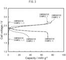
FIG. 3 is a graph showing charge-discharge curves of the fluoride-ion batteries of Comparative Examples 1 to 4. -
FIG. 4 is a graph showing charge-discharge curves of the fluoride-ion batteries of Examples 6 to 10 and Comparative Example 5. -
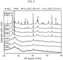
FIG. 5 is a graph showing X-ray diffraction (XRD) patterns of Examples 4 and 6 to 10 and Comparative Example 5. -
FIG. 6 is a graph showing an XRD pattern of standard CeO2 for FWHM ratio calculation. - Hereinafter, embodiments of the present disclosure will be described in detail. The present disclosure is not limited to the following embodiments, and various modifications can be made within the scope of the disclosure.
- The fluoride-ion battery of the present disclosure comprises a positive electrode active material layer, a negative electrode active material layer, and an electrolyte layer formed between the positive electrode active material layer and the negative electrode active material layer. In the fluoride-ion battery of the present disclosure, the negative electrode active material layer contains metallic magnesium, magnesium fluoride, and calcium barium fluoride, wherein a mass ratio of metallic magnesium to magnesium fluoride is 0.1 to 10.0.
- By including calcium barium fluoride, metallic magnesium, and magnesium fluoride in the negative electrode active material layer and setting the mass ratio of metallic magnesium to magnesium fluoride to a predetermined range, a fluoride-ion battery comprising the negative electrode active material layer can achieve high charge and discharge capacities.
- Although not intended to be bound by any theory, the reason therefor is believed to be as follows. Specifically, as a first-stage reaction during charging, magnesium fluoride is initially reacted to release fluoride ions and generate metallic magnesium. As a second-stage reaction, metallic magnesium in the negative electrode active material layer comprising the metallic magnesium generated in the first stage then forms an alloy with calcium and barium in calcium barium fluoride and releases fluoride ions. This reverse reaction during discharging causes the occlusion of fluoride ions. In other words, the fluoride-ion battery of the present disclosure is considered to be capable of achieving high charge and discharge capacities due to the occurrence of the two stages of release (charging) and occlusion (discharging) of fluoride ions. Further, it is considered that since the blended metallic magnesium also functions as an electron conductive aid to contribute the progression of efficient charging and discharging, the fluoride-ion battery of the present disclosure is capable of achieving high charge and discharge capacities.
-
FIG. 1 is a schematic diagram showing one example of the fluoride-ion battery of the present disclosure. The fluoride-ion battery 1 shown inFIG. 1 comprises a positive electrodeactive material layer 20, a negative electrodeactive material layer 40, anelectrolyte layer 30 formed between the positive electrodeactive material layer 20 and the negative electrodeactive material layer 40, a positive electrodecurrent collector 10 for collecting current of the positive electrodeactive material layer 20, and a negative electrodecurrent collector 50 for collecting current of the negative electrodeactive material layer 40. - The fluoride-ion battery of the present disclosure may be a liquid-based battery or a solid-state battery, particularly an all-solid-state battery. With regard to the present disclosure, a solid-state battery means a battery using a solid electrolyte. The fluoride-ion battery of the present disclosure may be a primary battery, or may be a secondary battery. Examples of the form of the fluoride-ion battery of the present disclosure include coin type, laminate type, cylindrical type, and rectangular type.
- In the present disclosure, the negative electrode active material layer comprises metallic magnesium, magnesium fluoride, and calcium barium fluoride.
- In the present disclosure, the negative electrode active material layer comprises metallic magnesium.
- The blending ratio of metallic magnesium in the negative electrode active material layer is, for example, 1% by weight or greater and may be 3% by weight or greater, or may be 5% by weight or greater. The blending ratio of metallic magnesium is, for example, 55% by weight or less and may be 45% by weight or less, or may be 35% by weight or less.
- In the present disclosure, the negative electrode active material layer comprises magnesium fluoride (MgF2). MgF2 functions as a negative electrode active material.
- In the present disclosure, the ratio (FWHMsam./FWHMref.) of the first FWHM (XRD half width) of the peak near 2θ = 40.4 deg. in the XRD spectrum of MgF2 to the second FWHM (XRD half width) of the peak near 2θ = 47.5 deg. in the XRD spectrum of CeO2, measured using CuKa radiation, may be 1.5 or greater.
- Crystallinity (crystallite size) is known to correlate with the peak half width FWHM (full width at half maximum) in XRD measurements. The smaller the FWHM, the higher the crystallinity (the large the crystallite size is). However, since the absolute value of calculated FWHM depends on the XRD measurement apparatus, conditions, and calculation method, the ratio of FWHMsam. of a sample (MgF2 in the negative electrode active material layer) to FWHMref. of a reference material CeO2 (distributed by the National Institute of Standards and Technology or NIST), which is measured and calculated in the same manner as the sample, is evaluated in the present disclosure. A smaller FWHMsam./FWHMref. represents higher crystallinity.
- The FWHM is calculated individually for each peak in an XRD pattern. In the present disclosure, among the peaks derived from MgF2 in the negative electrode active material layer as the sample, FWHMsam. is calculated for the peak on the MgF2 (111) plane confirmed near 2θ of 40.4 deg. in a measurement using CuKa radiation, as a peak having a relatively high intensity and easily separated from other peaks. For the reference material, FWHMref. is calculated for the peak on the CeO2 (220) plane confirmed near 2θ of 47.5 deg.
- The value of FWHMsam./FWHMref. is preferably 1.5 or greater, and more preferably 8 or greater. The value of FWHMsam./FWHMref. is preferably 10.0 or less, and more preferably 9.0 or less. When FWHMsam./FWHMref. is within the above range, the charge and discharge capacities of the fluoride-ion battery are improved.
- Although not intended to be bound by any theory, the reason therefor is considered that when crystallinity of MgF2 crystals is reduced (crystallite size is decreased), fluoride-ion diffusion length in the active material particles of MgF2 is shortened, and charge and discharge reactions proceed efficiently.
- The blending ratio of magnesium fluoride in the negative electrode active material layer is, for example, 1% by weight or greater and may be 3% by weight or greater, or may be 5% by weight or greater. The blending ratio of magnesium fluoride is, for example, 55% by weight or less and may be 45% by weight or less, or may be 35% by weight or less.
- The mass ratio (Mg/MgF2) of metallic magnesium to magnesium fluoride is 0.1 to 10.0, and preferably 0.1 to 5.0. When Mg/MgF2 is within the above range, the charge and discharge capacities of the fluoride-ion battery can be increased.
- The method of the present disclosure for manufacturing a negative electrode active material for a fluoride-ion battery comprises applying mechanical impact to magnesium fluoride to change a ratio of the first FWHM (XRD half width) of the peak near 2θ = 40.4 deg. in the XRD spectrum of magnesium fluoride to the second FWHM (XRD half width) of the peak near 2θ = 47.5 deg. in the XRD spectrum of NIST standard CeO2, measured using CuKa radiation, to 1.5 or greater.
- Examples of the method of applying mechanical impact include mechanical milling, and specifically include a ball mill. In this case, rotational speed of the ball mill and mixing time can be adjusted to control FWHMsam./FWHMref.
- The rotational speed of the ball mill is, for example, 300 rpm or more, and preferably 400 rpm or more, or 600 rpm or less, and preferably 500 rpm or less.
- The mixing with a ball mill can be carried out for a time period of, for example, 1 h or more, 2 h or more, or 3 h or more.
- In the present disclosure, the negative electrode active material layer comprises calcium barium fluoride (Ca1-xBaxF2). Ca1-xBaxF2 also functions as a negative electrode active material. Specifically, a negative electrode active material is generated from Ca1-xBaxF2 in a self-forming manner.
- Ca1-xBaxF2 can be obtained, for example, by mechanical milling of a mixture containing calcium fluoride (CaF2) and barium fluoride (BaF2). Examples of the means of mechanical milling can include, but are not particularly limited to, mixing with a ball mill.
- The x in Ca1-xBaxF2 is not particularly limited as long as 0 < x < 1 is satisfied, and may be 0.30 or greater, may be 0.35 or greater, or may be 0.40 or greater. The x may be 0.70 or less, may be 0.65 or less, or may be 0.60 or less. Particularly, when x satisfies 0.45 ≤ x ≤ 0.65, a satisfactory reversible capacity is obtained.
- The blending ratio of Ca1-xBaxF2 in the negative electrode active material layer is, for example 45% by weight or greater and may be 50% by weight or greater, or may be 55% by weight or greater. The blending ratio of Ca1-xBaxF2 is, for example, 75% by weight or less and may be 70% by weight or less, or may be 65% by weight or less.
- The negative electrode active material layer of the present disclosure may further contain at least one of an electron conductive aid and a binder, if necessary. Examples of the electron conductive aid include carbon materials. Examples of the carbon material include carbon blacks such as acetylene black, Ketjen black, furnace black, and thermal black; graphene, fullerene, and carbon nanotubes. Examples of the binder include fluorine-based binders such as polyvinylidene fluoride (PVDF) and polytetrafluoroethylene (PTFE).
- The thickness of the negative electrode active material layer is not particularly limited, and can be appropriately adjusted in accordance with the configuration of the battery.
- The positive electrode active material layer of the present disclosure is a layer containing at least a positive electrode active material. The positive electrode active material layer may further contain at least one of an electron conductive aid and a binder, if necessary.
- The positive electrode active material is generally an active material that is defluorinated during discharging. Examples of the positive electrode active material include elemental metals, alloys, metal oxides, and fluorides thereof. Examples of the metallic element contained in the positive electrode active material can include Cu, Ag, Ni, Co, Pb, Ce, Mn, Au, Pt, Rh, V, Os, Ru, Fe, Cr, Bi, Nb, Sb, Ti, Sn, and Zn. Of these, the positive electrode active material is preferably Cu, CuFz, Fe, FeFz, Ag, or AgFz. The z is a real number greater than 0. Additional examples of the positive electrode active material include carbon materials and fluorides thereof. Examples of the carbon materials include graphite, coke, and carbon nanotubes. Further additional examples of the positive electrode active material include polymer materials. Examples of the polymer materials include polyaniline, polypyrrole, polyacetylene, and polythiophene. Further additional examples of the positive electrode active material include metal sulfides. Examples of the metal sulfides include Cu2S, CuS, FeS, and FeS2.
- The content of the positive electrode active material in the positive electrode active material layer is not particularly limited, but is preferably large from the viewpoint of capacity. The content of the positive electrode active material is, for example, 30% by weight or greater and may be 50% by weight or greater, or may be 70% by weight or greater.
- The descriptions relating to the solid electrolyte layer of the present disclosure can be referenced regarding the solid electrolyte.
- The descriptions relating to the negative electrode active material layer of the present disclosure can be referenced regarding the electron conductive aid and the binder.
- The thickness of the positive electrode active material layer is not particularly limited, and can be appropriately adjusted in accordance with the configuration of the battery.
- The electrolyte layer of the present disclosure is a layer formed between the positive electrode active material layer and the negative electrode active material layer.
- When the fluoride-ion battery of the present disclosure is a liquid-based battery, the electrolyte layer can be composed of, for example, an electrolytic solution and an optional separator.
- The electrolytic solution can contain, for example, a fluoride salt and an organic solvent. Examples of the fluoride salt can include inorganic fluoride salts, organic fluoride salts, and ionic liquids. As one example of the inorganic fluoride salt, XF (X is Li, Na, K, Rb, or Cs) can be included. As one example of the cation of the organic fluoride salt, an alkyl ammonium cation such as a tetramethylammonium cation can be included.
- The organic solvent of the electrolytic solution is generally a solvent that dissolves a fluoride salt. Examples of the organic solvent can include glymes such as triethylene glycol dimethyl ether (G3) and tetraethylene glycol dimethyl ether (G4); cyclic carbonates such as ethylene carbonate (EC), fluoroethylene carbonate (FEC), difluoroethylene carbonate (DFEC), propylene carbonate (PC), and butylene carbonate (BC); and chain carbonates such as dimethyl carbonate (DMC), diethyl carbonate (DEC), and ethyl methyl carbonate (EMC). An ionic liquid may be used as the organic solvent.
- The separator is not particularly limited as long as the composition thereof is composed to withstand the use range of a fluoride-ion battery. Examples of the separator can include polymeric nonwoven fabrics such as polypropylene nonwoven fabrics and polyethylene nonwoven fabrics; and microporous films of olefin-based resins such as polyethylene and polypropylene.
- When the fluoride-ion battery of the present disclosure is a solid-state battery, the electrolyte layer may be, for example, a layer of a solid electrolyte. In this case, the electrolyte layer may further contain a binder, if necessary.
- The solid electrolyte is not particularly limited as long as the material thereof can be used in a fluoride-ion battery, and is exemplified by inorganic fluorides. Examples of the inorganic fluoride include fluorides containing lanthanoid elements such as La and Ce; fluorides containing alkaline earth elements such as Ca, Sr, and Ba; fluorides containing Group 14 elements such as Pb and Sn; and fluorides containing alkali elements such as Li, Na, K, Rb, and Cs. The solid electrolyte is preferably Ca1-xBaxF2.
- The descriptions relating to the negative electrode active material layer of the present disclosure can be referenced regarding the binder.
- The fluoride-ion battery of the present disclosure preferably comprises a positive electrode current collector for collecting current of the positive electrode active material layer, a negative electrode current collector for collecting current of the negative electrode active material layer, and a battery case housing the members described above. Examples of the form of the current collectors include a foil, a mesh, and a porous material. A conventionally known battery case can be used as the battery case.
- The charge and discharge capacities of the fluoride-ion battery of the present disclosure, as specific capacities normalized by the weight of the negative electrode mixture, can be 100 mAh/g or more.
- CaF2 and BaF2 were prepared as raw materials and weighed so as to have a molar ratio of CaF2:BaF2 = 50:50. The weighed CaF2 and BaF2 were mixed by mechanical milling using a ball mill apparatus (planetary series ball mill premium line PL-7, manufactured by Fritsch GmbH) in a dry argon atmosphere at 600 rpm for 20 h, and the mixture was reacted to obtain Ca0.5Ba0.5F2 in a powder form.
- Mg, MgF2, the above Ca0.5Ba0.5F2, and acetylene black (AB) as an electron conductive aid were weighed at the blending ratio (% by weight) indicated in Table 1 and mixed using a ball mill apparatus (planetary series ball mill premium line PL-7, manufactured by Fritsch GmbH) in a dry argon atmosphere at 600 rpm for 3 h to obtain a negative electrode mixture in a powder form.
- CaF2 and BaF2 were prepared as raw materials and weighed so as to have a molar ratio of CaF2:BaF2 = 60:40. These were mixed by mechanical milling using a ball mill apparatus (planetary series ball mill premium line PL-7, manufactured by Fritsch GmbH) in a dry argon atmosphere at 600 rpm for 20 h, and the mixture was reacted to obtain a solid electrolyte (Ca0.6Ba0.4F2) in a powder form.
- The following was used as the components of the fluoride-ion battery.
- · Negative electrode current collector: platinum foil
- · Negative electrode active material layer: green compact formed using 10 mg of the above negative electrode mixture powder
- · Electrolyte layer: green compact formed using 100 mg of the above solid electrolyte powder
- · Positive electrode active material layer: lead plate (220 mg)
- · Positive electrode current collector: aluminum foil
- The negative electrode current collector, negative electrode active material layer, electrolyte layer, positive electrode active material layer, and positive electrode current collector were laminated in this order to produce an all-solid-state fluoride-ion battery.
- Except that the mass ratios of the negative electrode mixture were changed as indicated in Table 1, all-solid-state fluoride-ion batteries of Examples 2 to 5 and Comparative Examples 1 to 4 were produced in the same manner as in Example 1.
- The fluoride-ion batteries of Examples 1 to 5 and Comparative Examples 1 to 4 were each charged and discharged once at a test temperature of 200 °C and a current density of 0.05 mA/cm2 while evacuated in a sealed container. The end-of-charge voltage and end-of-discharge voltage were 2.7 V and 1.8 V, respectively. An electrochemical measurement system equipped with a frequency response analyzer (VMP-300 high-performance electrochemical measurement system, manufactured by Bio-Logic Science Instruments Ltd.) was used for the charge-discharge test.
- The results of the charge-discharge tests are shown in Table 1,
FIG. 2 (Examples 1 to 5), andFIG. 3 (Comparative Examples 1 to 4). Note that the charge capacity and discharge capacity in each test are shown as specific capacities normalized by the weight of the negative electrode mixture.[Table 1] Example Mg/MgF2 Mg [%] MgF2 [%] Ca0.5Ba0.5F2 1%] AB [%] Charge capacity [mAh/g] Discharge capacity [mAh/g] Example 1 3.88 31 8 58 3 139 101 Example 2 1.79 25 14 58 3 177 138 Example 3 1.05 20 19 58 3 204 187 Example 4 0.34 10 29 58 3 273 252 Example 5 0.15 5 34 58 3 346 320 Comparative Example 1 0.08 3 36 58 3 0 0 Comparative Example 2 0.03 1 38 58 3 0 0 Comparative Example 3 0.08 3 36 54 7 75 38 Comparative Example 4 - 39 0 58 3 78 71 - As shown in Table 1,
FIG. 2 , andFIG. 3 , the charge and discharge capacities of fluoride-ion batteries of the Examples, wherein Mg/MgF2 was set within the range of the present disclosure, were large. - Although not intended to be bound by any theory, the reason therefore is believed to be as follows. Specifically, as the first-stage reaction during charging, MgF2 is initially reacted to release fluoride ions and generate Mg. As the second-stage reaction, Mg in the negative electrode mixture comprising Mg generated in the first stage then forms an alloy with Ca and Ba in Ca1-xBaxF2 and releases fluoride ions. This reverse reaction during discharging causes the occlusion of fluoride ions. In other words, it is believed that high charge and discharge capacities are obtained due to the occurrence of the two stages of release (charging) and occlusion (discharging) of fluoride ions.
- In the above mechanism, it is considered that the smaller the Mg/MgF2 ratio, the higher the theoretical capacity. However, the actual charge and discharge capacities were the largest in a composition comprising a small amount of Mg (Example 5). On the other hand, charging and discharging could not be carried out when Mg/MgF2 was less than the lower limit of the range of the present disclosure, even when Mg was contained (Comparative Examples 1 and 2). Presumably, this is because the blended Mg also functions as an electron conductive aid and the blending of a small amount of Mg contributes to efficient charging and discharging. This presumption is considered to be supported by Comparative Example 3, wherein Mg/MgF2 was set smaller than the range of the present disclosure and the ratio of AB as an electron conductive aid was increased, in that although the values of the charge and discharge capacities were smaller compared to the Examples, charging and discharging could be carried out.
- Except that the rotational speeds and times of ball mill (BM) mixing in the production of the negative electrode mixture were changed as indicated in Table 2, all-solid-state fluoride-ion batteries of Examples 6 to 10 and Comparative Example 5 were produced in the same manner as in Example 4.
- In order to examine the effect of crystallinity of MgF2 in the negative electrode mixture on charge and discharge capacities, charge-discharge tests and XRD measurements were carried out on the negative electrode mixtures obtained in Examples 4 and 6 to 10 and Comparative Example 5. The method of the charge-discharge test is as described above, and the method of XRD measurement is as indicated below.
- Measurements were carried out by a parafocusing method with CuKa radiation, using the SmartLab apparatus manufactured by Rigaku Corporation, under conditions of a tube voltage of 45 kV and a tube current of 200 mA. The above reference material CeO2 was measured under the same conditions. Each of the resulting XRD patterns shown in
FIGS. 4 and5 was subjected to pattern fitting analysis using the analysis software PDXL made by Rigaku Corporation to calculate the half width FWHM. The results are shown in Table 2 andFIG. 6 .[Table 2] Example BM rotational speed [rpm] BM time [h] FWHMsam. [deg.] FWHMsam. /FWHMref. Charge capacity [mAh/g] Discharge capacity [mAh/g] Example 4 600 3 0.691 9.68 273 252 Example 6 500 3 0.601 8.42 314 295 Example 7 400 3 0.572 8.01 343 315 Example 8 300 3 0.139 1.95 271 255 Example 9 300 2 0.121 0.69 216 205 Example 10 300 1 0.116 1.62 196 168 Comparative Example 5 200 3 0.0961 1.35 83 80 - As shown in Table 2 and
FIG. 6 , the charge and discharge capacities of fluoride-ion batteries of the Examples, wherein FWHMsam./FWHMref. was set to greater than 1.5 by reducing the crystallinity of MgF2 in the negative electrode mixture, were large. - Although not intended to be bound by any theory, the reason therefor is believed to be that when crystallinity of MgF2 crystals is reduced (crystallite size is decreased), fluoride-ion diffusion length in the active material particles of MgF2 is shortened, and charge and discharge reactions proceed efficiently.
-
- 1
- fluoride-ion battery
- 10
- positive electrode current collector layer
- 20
- positive electrode active material layer
- 30
- electrolyte layer
- 40
- negative electrode active material layer
- 50
- negative electrode current collector layer
Claims (8)
- A fluoride-ion battery, comprising a positive electrode active material layer, a negative electrode active material layer, and an electrolyte layer formed between the positive electrode active material layer and the negative electrode active material layer, whereinthe negative electrode active material layer contains metallic magnesium, magnesium fluoride, and calcium barium fluoride, anda mass ratio of the metallic magnesium to the magnesium fluoride is 0.1 to 10.0.
- The fluoride-ion battery according to claim 1, wherein a ratio of a first FWHM (XRD half width) of a peak near 2θ = 40.4 deg. in an XRD spectrum of the magnesium fluoride to a second FWHM (XRD half width) of a peak near 2θ = 47.5 deg. in an XRD spectrum of NIST standard CeO2, measured using CuKa radiation, is 1.5 or greater.
- The fluoride-ion battery according to claims 1 or 2, wherein the electrolyte layer comprises calcium barium fluoride.
- The fluoride-ion battery according to any one of claims 1 or 2, wherein charge and discharge capacities are 100 mAh/g or more.
- A negative electrode active material for a fluoride-ion battery, comprising magnesium fluoride, wherein
a ratio of a first FWHM (XRD half width) of a peak near 2θ = 40.4 deg. in an XRD spectrum of the magnesium fluoride to a second FWHM (XRD half width) of a peak near 2θ = 47.5 deg. in an XRD spectrum of NIST standard CeO2, measured using CuKa radiation, is 1.5 or greater. - A method for manufacturing the negative electrode active material according to claim 5, comprising applying mechanical impact to magnesium fluoride to change a ratio of a first FWHM (XRD half width) of a peak near 2θ = 40.4 deg. in an XRD spectrum of the magnesium fluoride to a second FWHM (XRD half width) of a peak near 2θ = 47.5 deg. in an XRD spectrum of NIST standard CeO2, measured using CuKa radiation, to 1.5 or greater.
- The method according to claim 6, wherein the mechanical impact is applied by a ball mill.
- The method according to claim 7, wherein a rotational speed of the ball mill is 300 rpm or more.
Applications Claiming Priority (1)
| Application Number | Priority Date | Filing Date | Title |
|---|---|---|---|
| JP2023048673A JP7700812B2 (en) | 2023-03-24 | 2023-03-24 | Fluoride ion battery, negative electrode active material for fluoride ion battery, and method for manufacturing negative electrode active material for fluoride ion battery |
Publications (1)
| Publication Number | Publication Date |
|---|---|
| EP4451369A1 true EP4451369A1 (en) | 2024-10-23 |
Family
ID=89722972
Family Applications (1)
| Application Number | Title | Priority Date | Filing Date |
|---|---|---|---|
| EP24153869.3A Pending EP4451369A1 (en) | 2023-03-24 | 2024-01-25 | Fluoride-ion battery, negative electrode active material for fluoride-ion battery, and method for manufacturing negative electrode active material for fluoride-ion battery |
Country Status (5)
| Country | Link |
|---|---|
| US (1) | US20240322161A1 (en) |
| EP (1) | EP4451369A1 (en) |
| JP (1) | JP7700812B2 (en) |
| KR (1) | KR102928523B1 (en) |
| CN (1) | CN118693250A (en) |
Citations (3)
| Publication number | Priority date | Publication date | Assignee | Title |
|---|---|---|---|---|
| US20150072134A1 (en) * | 2012-05-29 | 2015-03-12 | Stella Chemifa Corporation | Magnesium fluoride particles, method for producing magnesium fluoride particles, dispersion solution of magnesium fluoride particles, method for producing dispersion solution of magnesium fluoride particles, composition for forming low refractive index layer, method for producing composition for forming a low refractive index layer, substrate with low refractive index layer, and method for manufacturing substrate with low refractive index layer |
| US20190207244A1 (en) * | 2017-12-28 | 2019-07-04 | Panasonic Corporation | Fluoride ion conductor containing rubidium, magnesium, and fluorine, and fluoride ion secondary battery including the same |
| US20220263083A1 (en) * | 2021-02-12 | 2022-08-18 | Toyota Jidosha Kabushiki Kaisha | Anode material and fluoride ion battery |
Family Cites Families (5)
| Publication number | Priority date | Publication date | Assignee | Title |
|---|---|---|---|---|
| JP2009043477A (en) | 2007-08-07 | 2009-02-26 | Sony Corp | Positive electrode active material, positive electrode and non-aqueous electrolyte battery using the same |
| JP6852653B2 (en) * | 2017-11-07 | 2021-03-31 | トヨタ自動車株式会社 | Positive electrode active material and fluoride ion battery |
| JP7172574B2 (en) * | 2018-12-25 | 2022-11-16 | トヨタ自動車株式会社 | Solid electrolyte and fluoride ion batteries |
| CN112786862A (en) | 2021-01-26 | 2021-05-11 | 复旦大学 | Fluoride surface-modified secondary battery carbon negative electrode material and preparation method thereof |
| CN114883547B (en) | 2022-05-20 | 2024-03-26 | 湖南钠邦新能源有限公司 | Na (Na) 2 Fe x M y PO 4 F@MF z @C composite material, preparation method thereof and application thereof in sodium ion battery |
-
2023
- 2023-03-24 JP JP2023048673A patent/JP7700812B2/en active Active
-
2024
- 2024-01-25 US US18/422,802 patent/US20240322161A1/en active Pending
- 2024-01-25 EP EP24153869.3A patent/EP4451369A1/en active Pending
- 2024-03-11 KR KR1020240034040A patent/KR102928523B1/en active Active
- 2024-03-13 CN CN202410282543.0A patent/CN118693250A/en active Pending
Patent Citations (4)
| Publication number | Priority date | Publication date | Assignee | Title |
|---|---|---|---|---|
| US20150072134A1 (en) * | 2012-05-29 | 2015-03-12 | Stella Chemifa Corporation | Magnesium fluoride particles, method for producing magnesium fluoride particles, dispersion solution of magnesium fluoride particles, method for producing dispersion solution of magnesium fluoride particles, composition for forming low refractive index layer, method for producing composition for forming a low refractive index layer, substrate with low refractive index layer, and method for manufacturing substrate with low refractive index layer |
| US20190207244A1 (en) * | 2017-12-28 | 2019-07-04 | Panasonic Corporation | Fluoride ion conductor containing rubidium, magnesium, and fluorine, and fluoride ion secondary battery including the same |
| US20220263083A1 (en) * | 2021-02-12 | 2022-08-18 | Toyota Jidosha Kabushiki Kaisha | Anode material and fluoride ion battery |
| JP2022123264A (en) | 2021-02-12 | 2022-08-24 | トヨタ自動車株式会社 | Anode material and fluoride ion battery |
Also Published As
| Publication number | Publication date |
|---|---|
| US20240322161A1 (en) | 2024-09-26 |
| JP7700812B2 (en) | 2025-07-01 |
| KR102928523B1 (en) | 2026-02-19 |
| KR20240143864A (en) | 2024-10-02 |
| JP2024137230A (en) | 2024-10-07 |
| CN118693250A (en) | 2024-09-24 |
Similar Documents
| Publication | Publication Date | Title |
|---|---|---|
| EP2575200B1 (en) | Positive electrode material | |
| US8377591B2 (en) | Anode material for secondary battery, anode for secondary battery and secondary battery therewith | |
| US12288879B2 (en) | Cathode active material and fluoride ion battery | |
| US20120321955A1 (en) | Lithium-ion secondary battery | |
| EP2490287B1 (en) | Nonaqueous electrolyte lithium ion secondary battery | |
| KR102256295B1 (en) | Negative active material, negative electrode and lithium secondary battery including the same, and method of preparing the negative active material | |
| EP3920284B1 (en) | Active material, negative-electrode active material, and fluoride-ion secondary battery | |
| EP3410518B1 (en) | Cathode active material and fluoride ion battery | |
| EP0682377A1 (en) | Lithium secondary battery | |
| US20160233491A1 (en) | Bismuth-antimony anodes for lithium or sodium ion batteries | |
| US20200403224A1 (en) | Lithium molybdate anode material | |
| KR20190130483A (en) | Cathode active material and fluoride ion battery | |
| KR20220115869A (en) | Anode material and fluoride ion battery | |
| EP4451369A1 (en) | Fluoride-ion battery, negative electrode active material for fluoride-ion battery, and method for manufacturing negative electrode active material for fluoride-ion battery | |
| EP4174023A1 (en) | Positive electrode active material for lithium-ion battery, production method therefor, and lithium-ion battery | |
| EP4723211A1 (en) | Cathod active material for lithium secondary battery and manufacturing method therefor | |
| US20230395799A1 (en) | Positive electrode active material for fluoride ion battery and fluoride ion battery | |
| JP7693730B2 (en) | Positive electrode active material for fluoride ion battery and fluoride ion battery | |
| EP4401171A1 (en) | Negative electrode active material for fluoride ion battery, negative electrode active material layer for fluoride ion battery, fluoride ion battery, and method for producing negative electrode active material for fluoride ion battery | |
| EP4432399A1 (en) | Negative electrode active material for fluoride-ion battery, negative electrode active material layer for fluoride-ion battery, composition for forming negative electrode active material layer for fluoride-ion battery, fluoride-ion battery, method for manufacturing negative electrode active material for fluoride-ion battery, and method for manufacturing fluoride-ion battery | |
| US20240250258A1 (en) | Positive electrode active material for fluoride ion battery and fluoride ion battery | |
| US20250230054A1 (en) | Negative electrode active material for fluoride-ion battery and method for manufacturing thereof, negative electrode mixture, and fluoride-ion battery | |
| JP7779293B2 (en) | Positive electrode active material for fluoride ion battery, and fluoride ion battery | |
| JP7088126B2 (en) | Fluoride ion battery | |
| JP2023079855A (en) | Positive electrode active material and fluoride ion battery |
Legal Events
| Date | Code | Title | Description |
|---|---|---|---|
| PUAI | Public reference made under article 153(3) epc to a published international application that has entered the european phase |
Free format text: ORIGINAL CODE: 0009012 |
|
| STAA | Information on the status of an ep patent application or granted ep patent |
Free format text: STATUS: REQUEST FOR EXAMINATION WAS MADE |
|
| 17P | Request for examination filed |
Effective date: 20240205 |
|
| AK | Designated contracting states |
Kind code of ref document: A1 Designated state(s): AL AT BE BG CH CY CZ DE DK EE ES FI FR GB GR HR HU IE IS IT LI LT LU LV MC ME MK MT NL NO PL PT RO RS SE SI SK SM TR |